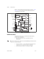
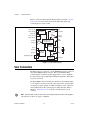
1
Motion Control NI 951x User Manual NI 951x User Manual July 2009 372153B-01 Support Worldwide Technical Support and Product Information ni.com National Instruments Corporate Headquarters 11500 North Mopac Expressway Austin, Texas 78759-3504 USA Tel: 512 683 0100 Worldwide Offices Australia 1800 300 800, Austria 43 662 457990-0, Belgium 32 (0) 2 757 0020, Brazil 55 11 3262 3599, Canada 800 433 3488, China 86 21 5050 9800, Czech Republic 420 224 235 774, Denmark 45 45 76 26 00, Finland 358 (0) 9 725 72511, France 01 57 66 24 24, Germany 49 89 7413130, India 91 80 41190000, Israel 972 3 6393737, Italy 39 02 41309277, Japan 0120-527196, Korea 82 02 3451 3400, Lebanon 961 (0) 1 33 28 28, Malaysia 1800 887710, Mexico 01 800 010 0793, Netherlands 31 (0) 348 433 466, New Zealand 0800 553 322, Norway 47 (0) 66 90 76 60, Poland 48 22 328 90 10, Portugal 351 210 311 210, Russia 7 495 783 6851, Singapore 1800 226 5886, Slovenia 386 3 425 42 00, South Africa 27 0 11 805 8197, Spain 34 91 640 0085, Sweden 46 (0) 8 587 895 00, Switzerland 41 56 2005151, Taiwan 886 02 2377 2222, Thailand 662 278 6777, Turkey 90 212 279 3031, United Kingdom 44 (0) 1635 523545 For further support information, refer to the Technical Support and Professional Services appendix. To comment on National Instruments documentation, refer to the National Instruments Web site at ni.com/info and enter the info code feedback. © 2009 National Instruments Corporation. All rights reserved. Important Information Warranty The NI 9512, NI 9514, and NI 9516 C Series modules are warranted against defects in materials and workmanship for a period of one year from the date of shipment, as evidenced by receipts or other documentation. National Instruments will, at its option, repair or replace equipment that proves to be defective during the warranty period. This warranty includes parts and labor. The media on which you receive National Instruments software are warranted not to fail to execute programming instructions, due to defects in materials and workmanship, for a period of 90 days from date of shipment, as evidenced by receipts or other documentation. National Instruments will, at its option, repair or replace software media that do not execute programming instructions if National Instruments receives notice of such defects during the warranty period. National Instruments does not warrant that the operation of the software shall be uninterrupted or error free. A Return Material Authorization (RMA) number must be obtained from the factory and clearly marked on the outside of the package before any equipment will be accepted for warranty work. National Instruments will pay the shipping costs of returning to the owner parts which are covered by warranty. National Instruments believes that the information in this document is accurate. The document has been carefully reviewed for technical accuracy. In the event that technical or typographical errors exist, National Instruments reserves the right to make changes to subsequent editions of this document without prior notice to holders of this edition. The reader should consult National Instruments if errors are suspected. In no event shall National Instruments be liable for any damages arising out of or related to this document or the information contained in it. EXCEPT AS SPECIFIED HEREIN, NATIONAL INSTRUMENTS MAKES NO WARRANTIES, EXPRESS OR IMPLIED, AND SPECIFICALLY DISCLAIMS ANY WARRANTY OF MERCHANTABILITY OR FITNESS FOR A PARTICULAR PURPOSE. CUSTOMER’S RIGHT TO RECOVER DAMAGES CAUSED BY FAULT OR NEGLIGENCE ON THE PART OF NATIONAL INSTRUMENTS SHALL BE LIMITED TO THE AMOUNT THERETOFORE PAID BY THE CUSTOMER. NATIONAL INSTRUMENTS WILL NOT BE LIABLE FOR DAMAGES RESULTING FROM LOSS OF DATA, PROFITS, USE OF PRODUCTS, OR INCIDENTAL OR CONSEQUENTIAL DAMAGES, EVEN IF ADVISED OF THE POSSIBILITY THEREOF. This limitation of the liability of National Instruments will apply regardless of the form of action, whether in contract or tort, including negligence. Any action against National Instruments must be brought within one year after the cause of action accrues. National Instruments shall not be liable for any delay in performance due to causes beyond its reasonable control. The warranty provided herein does not cover damages, defects, malfunctions, or service failures caused by owner’s failure to follow the National Instruments installation, operation, or maintenance instructions; owner’s modification of the product; owner’s abuse, misuse, or negligent acts; and power failure or surges, fire, flood, accident, actions of third parties, or other events outside reasonable control. Copyright Under the copyright laws, this publication may not be reproduced or transmitted in any form, electronic or mechanical, including photocopying, recording, storing in an information retrieval system, or translating, in whole or in part, without the prior written consent of National Instruments Corporation. National Instruments respects the intellectual property of others, and we ask our users to do the same. NI software is protected by copyright and other intellectual property laws. Where NI software may be used to reproduce software or other materials belonging to others, you may use NI software only to reproduce materials that you may reproduce in accordance with the terms of any applicable license or other legal restriction. Trademarks National Instruments, NI, ni.com, and LabVIEW are trademarks of National Instruments Corporation. Refer to the Terms of Use section on ni.com/legal for more information about National Instruments trademarks. Product and company names mentioned herein are trademarks or trade names of their respective companies. Members of the National Instruments Alliance Partner Program are business entities independent from National Instruments and have no agency, partnership, or joint-venture relationship with National Instruments. Patents For patents covering National Instruments products/technology, refer to the appropriate location: Help»Patents in your software, the patents.txt file on your media, or the National Instruments Patent Notice at ni.com/patents. WARNING REGARDING USE OF NATIONAL INSTRUMENTS PRODUCTS (1) NATIONAL INSTRUMENTS PRODUCTS ARE NOT DESIGNED WITH COMPONENTS AND TESTING FOR A LEVEL OF RELIABILITY SUITABLE FOR USE IN OR IN CONNECTION WITH SURGICAL IMPLANTS OR AS CRITICAL COMPONENTS IN ANY LIFE SUPPORT SYSTEMS WHOSE FAILURE TO PERFORM CAN REASONABLY BE EXPECTED TO CAUSE SIGNIFICANT INJURY TO A HUMAN. (2) IN ANY APPLICATION, INCLUDING THE ABOVE, RELIABILITY OF OPERATION OF THE SOFTWARE PRODUCTS CAN BE IMPAIRED BY ADVERSE FACTORS, INCLUDING BUT NOT LIMITED TO FLUCTUATIONS IN ELECTRICAL POWER SUPPLY, COMPUTER HARDWARE MALFUNCTIONS, COMPUTER OPERATING SYSTEM SOFTWARE FITNESS, FITNESS OF COMPILERS AND DEVELOPMENT SOFTWARE USED TO DEVELOP AN APPLICATION, INSTALLATION ERRORS, SOFTWARE AND HARDWARE COMPATIBILITY PROBLEMS, MALFUNCTIONS OR FAILURES OF ELECTRONIC MONITORING OR CONTROL DEVICES, TRANSIENT FAILURES OF ELECTRONIC SYSTEMS (HARDWARE AND/OR SOFTWARE), UNANTICIPATED USES OR MISUSES, OR ERRORS ON THE PART OF THE USER OR APPLICATIONS DESIGNER (ADVERSE FACTORS SUCH AS THESE ARE HEREAFTER COLLECTIVELY TERMED “SYSTEM FAILURES”). ANY APPLICATION WHERE A SYSTEM FAILURE WOULD CREATE A RISK OF HARM TO PROPERTY OR PERSONS (INCLUDING THE RISK OF BODILY INJURY AND DEATH) SHOULD NOT BE RELIANT SOLELY UPON ONE FORM OF ELECTRONIC SYSTEM DUE TO THE RISK OF SYSTEM FAILURE. TO AVOID DAMAGE, INJURY, OR DEATH, THE USER OR APPLICATION DESIGNER MUST TAKE REASONABLY PRUDENT STEPS TO PROTECT AGAINST SYSTEM FAILURES, INCLUDING BUT NOT LIMITED TO BACK-UP OR SHUT DOWN MECHANISMS. BECAUSE EACH END-USER SYSTEM IS CUSTOMIZED AND DIFFERS FROM NATIONAL INSTRUMENTS' TESTING PLATFORMS AND BECAUSE A USER OR APPLICATION DESIGNER MAY USE NATIONAL INSTRUMENTS PRODUCTS IN COMBINATION WITH OTHER PRODUCTS IN A MANNER NOT EVALUATED OR CONTEMPLATED BY NATIONAL INSTRUMENTS, THE USER OR APPLICATION DESIGNER IS ULTIMATELY RESPONSIBLE FOR VERIFYING AND VALIDATING THE SUITABILITY OF NATIONAL INSTRUMENTS PRODUCTS WHENEVER NATIONAL INSTRUMENTS PRODUCTS ARE INCORPORATED IN A SYSTEM OR APPLICATION, INCLUDING, WITHOUT LIMITATION, THE APPROPRIATE DESIGN, PROCESS AND SAFETY LEVEL OF SUCH SYSTEM OR APPLICATION. Compliance Electromagnetic Compatibility Information This hardware has been tested and found to comply with the applicable regulatory requirements and limits for electromagnetic compatibility (EMC) as indicated in the hardware’s Declaration of Conformity (DoC)1. These requirements and limits are designed to provide reasonable protection against harmful interference when the hardware is operated in the intended electromagnetic environment. In special cases, for example when either highly sensitive or noisy hardware is being used in close proximity, additional mitigation measures may have to be employed to minimize the potential for electromagnetic interference. While this hardware is compliant with the applicable regulatory EMC requirements, there is no guarantee that interference will not occur in a particular installation. To minimize the potential for the hardware to cause interference to radio and television reception or to experience unacceptable performance degradation, install and use this hardware in strict accordance with the instructions in the hardware documentation and the DoC1. If this hardware does cause interference with licensed radio communications services or other nearby electronics, which can be determined by turning the hardware off and on, you are encouraged to try to correct the interference by one or more of the following measures: • Reorient the antenna of the receiver (the device suffering interference). • Relocate the transmitter (the device generating interference) with respect to the receiver. • Plug the transmitter into a different outlet so that the transmitter and the receiver are on different branch circuits. Some hardware may require the use of a metal, shielded enclosure (windowless version) to meet the EMC requirements for special EMC environments such as, for marine use or in heavy industrial areas. Refer to the hardware’s user documentation and the DoC1 for product installation requirements. When the hardware is connected to a test object or to test leads, the system may become more sensitive to disturbances or may cause interference in the local electromagnetic environment. Operation of this hardware in a residential area is likely to cause harmful interference. Users are required to correct the interference at their own expense or cease operation of the hardware. Changes or modifications not expressly approved by National Instruments could void the user’s right to operate the hardware under the local regulatory rules. 1 The Declaration of Conformity (DoC) contains important EMC compliance information and instructions for the user or installer. To obtain the DoC for this product, visit ni.com/certification, search by model number or product line, and click the appropriate link in the Certification column. Contents About This Manual Conventions ...................................................................................................................ix Related Documentation..................................................................................................x Chapter 1 Introduction and Installation About the NI 951x Drive Interface Modules .................................................................1-1 Features............................................................................................................1-1 Hardware .........................................................................................................1-1 What You Need to Get Started ......................................................................................1-2 Using the NI 951x Modules in Scan Interface Mode ......................................1-2 Using the NI 951x Modules in LabVIEW FPGA Interface Mode..................1-3 Safety Information .........................................................................................................1-3 Special Conditions for Marine Applications ...................................................1-3 Optional Equipment .......................................................................................................1-4 Chapter 2 Hardware Overview NI 951x Connections .....................................................................................................2-2 NI 9512 Connections.......................................................................................2-2 NI 9514 Connections.......................................................................................2-4 NI 9516 Connections.......................................................................................2-6 User Connectors.............................................................................................................2-8 NI 9512 Connectors.........................................................................................2-9 NI 9514 Connectors.........................................................................................2-11 NI 9516 Connectors.........................................................................................2-13 LED Indicators...............................................................................................................2-15 Axis Status.......................................................................................................2-15 Encoder Active ................................................................................................2-15 Limit Active.....................................................................................................2-16 Axis Fault ........................................................................................................2-16 © National Instruments Corporation v NI 951x User Manual Contents Chapter 3 Signal Connections Power Connections........................................................................................................ 3-4 Command Signals.......................................................................................................... 3-4 Stepper Command Signals .............................................................................. 3-4 Step (CW)± and Direction (CCW)±................................................. 3-4 Servo Command Signals................................................................................. 3-7 Drive Command Output ................................................................... 3-7 Drive Command COM ..................................................................... 3-7 Additional Drive Signals................................................................................. 3-7 Drive Enable .................................................................................... 3-7 Motion I/O Signals ........................................................................................................ 3-9 Limit and Home Inputs ................................................................................... 3-9 Limit and Home Input Circuit .......................................................... 3-9 Encoder Inputs ................................................................................................ 3-11 Encoder Phase A/Phase B................................................................. 3-12 Encoder Index................................................................................... 3-12 Encoder Input Circuit ....................................................................... 3-13 Position Capture Input and Position Compare Output.................................... 3-14 Digital I/O Signals......................................................................................................... 3-15 Digital Inputs................................................................................................... 3-15 Digital Outputs................................................................................................ 3-17 Chapter 4 Accessory and Cable Connections Connection to P7000 Series Stepper Drives.................................................................. 4-1 NI 951x Connection Accessories .................................................................................. 4-5 37-Pin Terminal Block Pin Assignments........................................................ 4-5 Signal Connection Recommendations........................................................................... 4-7 General Connection Recommendations.......................................................... 4-7 Limit and Digital Input Connection Recommendations ................................. 4-8 Encoder Connection Recommendations ......................................................... 4-8 Connecting Optional Signals......................................................................................... 4-9 Connecting a Brake Signal.............................................................................. 4-9 NI 951x User Manual vi ni.com Contents Appendix A Specifications Appendix B Position Command Connections Appendix C Technical Support and Professional Services Glossary Index © National Instruments Corporation vii NI 951x User Manual About This Manual This manual describes the electrical and mechanical aspects of the National Instruments 951x C Series drive interface modules and contains information concerning installation and operation. Conventions This manual uses the following conventions: <> Angle brackets that contain numbers separated by an ellipsis represent a range of values associated with a bit or signal name—for example, AO <3..0>. » The » symbol leads you through nested menu items and dialog box options to a final action. The sequence File»Page Setup»Options directs you to pull down the File menu, select the Page Setup item, and select Options from the last dialog box. This icon denotes a tip, which alerts you to advisory information. This icon denotes a note, which alerts you to important information. This icon denotes a caution, which advises you of precautions to take to avoid injury, data loss, or a system crash. When this symbol is marked on a product, refer to the Safety Information section for information about precautions to take. This icon denotes that the component may be hot. Touching this component may result in bodily injury. bold Bold text denotes items that you must select or click in the software, such as menu items and dialog box options. Bold text also denotes parameter names. italic Italic text denotes variables, emphasis, a cross-reference, or an introduction to a key concept. Italic text also denotes text that is a placeholder for a word or value that you must supply. monospace Text in this font denotes text or characters that you should enter from the keyboard, sections of code, programming examples, and syntax examples. This font is also used for the proper names of disk drives, paths, directories, programs, subprograms, subroutines, device names, functions, operations, variables, filenames, and extensions. © National Instruments Corporation ix NI 951x User Manual About This Manual Related Documentation The following documents contain information you might find helpful as you read this manual: NI 951x User Manual • Operating Instructions for the controller and modules (shipped with the hardware and available from ni.com/manuals) • NI-Motion Help—Contains information about motion programming concepts and the NI-Motion architecture. Access the NI-Motion Help by going to Start»All Programs»NI-Motion»Documentation. • LabVIEW NI SoftMotion Module Help—Use this help file to learn about using NI SoftMotion in LabVIEW including information about function blocks and using NI SoftMotion with the LabVIEW Project. To access this help file from LabVIEW, select Help»Search the LabVIEW Help, then expand the LabVIEW NI SoftMotion Module book on the Contents tab. • LabVIEW Help—Contains LabVIEW, LabVIEW Real-Time Module, and LabVIEW FPGA Module programming concepts, instructions, and reference information. Access the LabVIEW Help by selecting Help»Search the LabVIEW Help from within LabVIEW. x ni.com Introduction and Installation 1 This chapter includes information about the features of the National Instruments 9512, 9514, and 9516 drive interface modules. The remainder of this document will refer to these modules collectively as NI 951x modules. Note About the NI 951x Drive Interface Modules The NI 951x drive interface modules are a family of C Series motion modules. These modules enable advanced motion with configuration and programming using NI LabVIEW. Features The NI 951x modules provide servo or stepper drive interface signals for a single axis, a full set of motion I/O including inputs for a home switch and limit switches, incremental encoder inputs for position feedback, and 0 to 30 V digital input and digital output lines. Refer to Chapter 3, Signal Connections, for more information about the signals available on each module. • The NI 9512 is a single-axis stepper or position command drive interface module with incremental encoder feedback. Refer to Appendix B, Position Command Connections, for information about using the NI 9512 module with position command servo drives. Note • The NI 9514 is a single-axis servo drive interface module with incremental encoder feedback. • The NI 9516 is a single-axis servo drive interface module with dual incremental encoder feedback. Hardware The NI 951x drive interface modules include a processor to run the spline interpolation engine and patented NI step generation algorithm or PID control loop/PIVff control loop. Working together they produce smoother motion resulting in precise motion control. © National Instruments Corporation 1-1 NI 951x User Manual Chapter 1 Introduction and Installation What You Need to Get Started Using the NI 951x Modules in Scan Interface Mode Scan Interface mode enables you to use C Series modules directly from the LabVIEW Real-Time Module. Refer to the CompactRIO Reference and Procedures (Scan Interface) section of the LabVIEW Help for more information about using C Series modules in Scan Interface mode. To set up and use the NI 951x drive interface modules in Scan Interface mode, you must have the following items: ❑ The following software packages and documentation: – Tip NI SoftMotion. This software package contains the following NI software products: • NI SoftMotion software • NI-Motion driver software – LabVIEW Development System – LabVIEW Real-Time Module – NI-RIO driver software Refer to the software documentation for installation instructions. ❑ The following hardware and documentation: – NI 9512, NI 9514, or NI 9516 drive interface module – External power supply Refer to the Power Requirements section of Appendix A, Specifications, for power supply requirements. Note – CompactRIO controller and chassis that support the RIO Scan Interface or – NI 951x User Manual NI 9144 distributed chassis 1-2 ni.com Chapter 1 Introduction and Installation Using the NI 951x Modules in LabVIEW FPGA Interface Mode LabVIEW FPGA Interface mode enables you to use C Series modules from LabVIEW FPGA VIs. Refer to the CompactRIO Reference and Procedures (FPGA Interface) section of the LabVIEW Help for more information about using C Series modules in LabVIEW FPGA Interface mode. To set up and use the NI 951x drive interface modules in LabVIEW FPGA Interface mode, you must have the following items: ❑ The following software packages and documentation: – Tip (optional) NI SoftMotion. This software package contains the following NI software products: • NI SoftMotion software • NI-Motion driver software – LabVIEW Development System – LabVIEW Real-Time Module – LabVIEW FPGA Module – NI-RIO driver software Refer to the software documentation for installation instructions. ❑ The following hardware and documentation: – NI 9512, NI 9514, or NI 9516 drive interface module – External power supply Refer to the Power Requirements section of Appendix A, Specifications, for power supply requirements. Note – CompactRIO controller and chassis Safety Information Special Conditions for Marine Applications Some modules are Lloyd’s Register (LR) Type Approved for marine applications. To verify Lloyd’s Register certification, visit ni.com/ certification and search for the LR certificate, or look for the Lloyd’s Register mark on the module. © National Instruments Corporation 1-3 NI 951x User Manual Chapter 1 Introduction and Installation Caution To meet radio frequency emission requirements for marine applications, use shielded cables and install the system in a metal enclosure. Suppression ferrites must be installed on power supply inputs near power entries to modules and controllers. Power supply and module cables must be separated on opposite sides of the enclosure and must enter and exit through opposing enclosure walls. Optional Equipment National Instruments offers several options for connecting NI 951x drive interface modules to external stepper drives or servo amplifiers including the following: • NI 9512-to-P7000 Stepper Drives Connectivity Bundle—Connects the NI 9512 to the P70530 or P70360 stepper drives available from NI. (NI part number 780552-01) • NI 951x Cable and Terminal Block Bundle—Connects the NI 951x module with the 37-pin spring terminal blocks. (NI part number 780553-01) • DSUB and MDR Solder Cup Connectors—Simplifies custom cable creation. NI part number for DSUB connector: 780549-01 NI part number for MDR connector: 780551-01 • DSUB to Pigtails Cable and MDR to Pigtails Cable—Simplifies custom cable creation. NI part number for DSUB cable: 193412-04 NI part number for MDR cable: 193413-04 Caution Do not use the recommended module power supplies to power a drive. Check your drive documentation for drive power supply requirements. • Note +24 V DC power supply Refer to the National Instruments Web site at ni.com for available power supplies. Refer to Chapter 4, Accessory and Cable Connections, for cable and terminal block pin assignments. For additional information about these and other available products refer to the National Instruments Web site at ni.com, or call your National Instruments sales representative. NI 951x User Manual 1-4 ni.com 2 Hardware Overview This chapter presents an overview of the National Instruments 951x drive interface module hardware, including connections and connector pin assignments. The following figure shows the NI 951x module. Figure 2-1. NI 951x Module © National Instruments Corporation 2-1 NI 951x User Manual Chapter 2 Hardware Overview NI 951x Connections This section contains connection information for each drive interface module, including connection diagrams for a complete system setup. NI 9512 Connections Complete the following steps to connect the NI 9512 stepper drive interface module to drives and other I/O: 1. Install the module in the chassis as specified in the chassis documentation. Refer to the NI SoftMotion Module book of the LabVIEW Help for information about chassis, slot, or software restrictions. Note 2. Connect the module to a drive and other I/O using the NI 9512-to-P7000 Stepper Drives Connectivity Bundle, the NI 951x Cable and Terminal Block Bundle, or a custom cable for direct connectivity. 3. Connect the NI 9512 module to an external power supply. Figure 2-2 shows a simplified connection diagram. Refer to Appendix B, Position Command Connections, for position command signal information and information about connecting the NI 9512 module to drives that support position command mode. Note Caution NI 951x User Manual Do not connect anything to pins marked Reserved. 2-2 ni.com Chapter 2 DSUB Connector Hardware Overview MDR Connector Step±/CW Encoder 0 Phase A, B, Index Direction±/CCW +5 V OUT Drive Fault Forward, Reverse Limit, Home Drive Enable Vsup NI 9512 Limit and Home Sensors NI Connection Accessory/ Custom Cable Power Supply Step±/CW Direction±/CCW Drive Drive Fault Drive Enable Motor Stepper Motor Encoder (optional) Figure 2-2. NI 9512 Connection Diagram Note The NI 9512 requires an external power supply. You can connect the external power supply to the Vsup input provided on the DSUB or MDR connector. Do not connect more than one external power supply to the module. © National Instruments Corporation 2-3 NI 951x User Manual Chapter 2 Hardware Overview Figure 2-3 shows the NI 9512 block diagram. Refer to Chapter 3, Signal Connections, for more information about the individual signals and connecting devices to the module. Phase A± (0) Receiver Circuitry Phase B± (0) Buffer Step ± Buffer Direction ± Buffer Position Compare Index± (0) Position Capture Buffer Microprocessor Drive Enable Home Forward Digital Output (0-1) Output Circuitry Reverse Input Circuitry Vsup Digital Input (0-3) COM +5V Reg +5 V OUT Figure 2-3. NI 9512 Block Diagram NI 9514 Connections Complete the following steps to connect the NI 9514 drive interface module to drives and other I/O: 1. Install the module in the chassis as specified in the chassis documentation. Refer to the NI SoftMotion Module book of the LabVIEW Help for information about chassis, slot, or software restrictions. Note NI 951x User Manual 2. Connect the module to a 37-pin terminal block using the NI 951x to 37-pin cable, or use a custom cable for direct connectivity. 3. Connect the NI 9514 module to an external power supply. 2-4 ni.com Chapter 2 Hardware Overview Figure 2-4 shows a simplified connection diagram. DSUB Connector MDR Connector Encoder 0 Phase A, B, Index Drive Command +5 V OUT Drive Enable Forward, Reverse Limit, Home Drive Fault Vsup NI 9514 Limit and Home Sensors NI Connection Accessory/ Custom Cable Power Supply Drive Command Drive Enable Drive Drive Fault Motor Servo Motor Encoder Figure 2-4. NI 9514 Connection Diagram Note The NI 9514 requires an external power supply. You can connect the external power supply to the Vsup input provided on the DSUB or MDR connector. Do not connect more than one external power supply to the module. Caution Do not connect anything to pins marked Reserved. © National Instruments Corporation 2-5 NI 951x User Manual Chapter 2 Hardware Overview Figure 2-5 shows the NI 9514 block diagram. Refer to Chapter 3, Signal Connections, for more information about the individual signals and connecting devices to the module. Phase A± (0) Receiver Circuitry Phase B± (0) Index± (0) Position Capture Buffer DAC Drive Command Buffer Position Compare Microprocessor (PID Loop) Drive Enable Home Output Circuitry Forward Reverse Vsup Input Circuitry COM Digital Input (0-1) +5V Reg +5 V OUT Figure 2-5. NI 9514 Block Diagram NI 9516 Connections Complete the following steps to connect the NI 9516 drive interface module to drives and other I/O: 1. Install the module in the chassis as specified in the chassis documentation. Refer to the NI SoftMotion Module book of the LabVIEW Help for information about chassis, slot, or software restrictions. Note 2. NI 951x User Manual Connect the module to a 37-pin terminal block using the NI 951x to 37-pin cable, or use a custom cable for direct connectivity. 2-6 ni.com Chapter 2 Hardware Overview Figure 2-6 shows a simplified connection diagram. DSUB Connector Drive Command MDR Connector Encoder 0 Phase A, B, Index Drive Enable Encoder 1 Phase A, B Drive Fault +5 V OUT Vsup Forward, Reverse Limit, Home NI 9516 Limit and Home Sensors NI Connection Accessory/ Custom Cable Power Supply Drive Command Drive Enable Drive Drive Fault Motor Servo Motor Encoder 0 Encoder 1 Figure 2-6. NI 9516 Connection Diagram Note The NI 9516 requires an external power supply. You can connect the external power supply to the Vsup input provided on the DSUB or MDR connector. Do not connect more than one external power supply to the module. Caution Do not connect anything to pins marked Reserved. © National Instruments Corporation 2-7 NI 951x User Manual Chapter 2 Hardware Overview Figure 2-7 shows the NI 9516 block diagram. Refer to Chapter 3, Signal Connections, for more information about the individual signals and connecting devices to the module. Phase A± (0) Phase B± (0) Receiver Circuitry DAC Drive Command Buffer Position Compare Index± (0) Phase A± (1) Phase B± (1) Position Capture Buffer Microprocessor (PID Loop) Output Circuitry Home Drive Enable Vsup Forward Reverse Input Circuitry COM Digital Input (0-1) +5V Reg +5 V OUT Figure 2-7. NI 9516 Block Diagram User Connectors The NI 951x has two connectors, a 15-pin DSUB drive interface connector and a 20-pin MDR feedback connector. The 15-pin DSUB includes command signals for interfacing with stepper drives or servo amplifiers, 0 to 30 V general-purpose digital input and digital output lines, and an input for power connection. The 20-pin MDR connector includes incremental encoder feedback inputs, a +5 V output for encoder power, home, limit, and position compare inputs, an output for position compare, an additional input for power connection, and an additional 0 to 30 V general-purpose digital input line. Refer to Chapter 3, Signal Connections, for details about the signals in each connector. The remainder of this document does not distinguish between drives and amplifiers. All references to drives also apply to amplifiers. Note NI 951x User Manual 2-8 ni.com Chapter 2 Hardware Overview NI 9512 Connectors Refer to Chapter 4, Accessory and Cable Connections, for cabling options and connection accessory pin assignments. Caution Do not connect anything to pins marked Reserved. Table 2-1. NI 9512 DSUB Control Connector Pin Assignments Connector 15 11 10 6 Pin 5 1 Signal 1 Reserved 2 Drive Enable 3 Digital Input 3 4 Digital Input 2 5 Digital Output 1 6 Reserved 7 COM 8 Digital Input 1 9 Direction (CCW)– 10 Step (CW)– 11 Digital Output 0 12 Vsup 13 Direction (CCW)+ 14 COM 15 Step (CW)+ Refer to Appendix B, Position Command Connections, for position command signal information and information about connecting the NI 9512 module to position command drives. Note © National Instruments Corporation 2-9 NI 951x User Manual Chapter 2 Hardware Overview Reverse Limit Reserved Vsup Reserved COM Encoder 0 Phase A+ Encoder 0 Phase A– Encoder 0 Phase B+ Position Capture Encoder 0 Phase B– 11 12 13 14 15 16 17 18 19 20 1 2 3 4 5 6 7 8 9 10 Forward Limit Home COM Digital Input 0 COM Encoder 0 Index+ Encoder 0 Index– COM +5 V OUT Position Compare Figure 2-8. NI 9512 MDR Connector Pin Assignments NI 951x User Manual 2-10 ni.com Chapter 2 Hardware Overview NI 9514 Connectors Refer to Chapter 4, Accessory and Cable Connections, for cabling options and connection accessory pin assignments. Caution Do not connect anything to pins marked Reserved. Table 2-2. NI 9514 DSUB Control Connector Pin Assignments Connector 15 11 10 6 © National Instruments Corporation Pin 5 1 2-11 Signal 1 Drive Command COM 2 Drive Enable 3 Reserved 4 Reserved 5 Reserved 6 Drive Command 7 COM 8 Digital Input 1 9 Reserved 10 Reserved 11 Reserved 12 Vsup 13 Reserved 14 COM 15 Reserved NI 951x User Manual Chapter 2 Hardware Overview Reverse Limit Reserved Vsup Reserved COM Encoder 0 Phase A+ Encoder 0 Phase A– Encoder 0 Phase B+ Position Capture Encoder 0 Phase B– 11 12 13 14 15 16 17 18 19 20 1 2 3 4 5 6 7 8 9 10 Forward Limit Home COM Digital Input 0 COM Encoder 0 Index+ Encoder 0 Index– COM +5 V OUT Position Compare Figure 2-9. NI 9514 MDR Connector Pin Assignments NI 951x User Manual 2-12 ni.com Chapter 2 Hardware Overview NI 9516 Connectors Caution Do not connect anything to pins marked Reserved. Refer to Chapter 4, Accessory and Cable Connections, for cabling options and connection accessory pin assignments. Table 2-3. NI 9516 DSUB Control Connector Pin Assignments Connector 15 10 11 © National Instruments Corporation 6 Pin 5 1 2-13 Signal 1 Drive Command COM 2 Drive Enable 3 Reserved 4 Reserved 5 Reserved 6 Drive Command 7 COM 8 Digital Input 1 9 Reserved 10 Reserved 11 Reserved 12 Vsup 13 Reserved 14 COM 15 Reserved NI 951x User Manual Chapter 2 Hardware Overview Reverse Limit Encoder 1 Phase A+ Vsup Encoder 1 Phase A– Encoder 1 Phase B+ Encoder 0 Phase A+ Encoder 0 Phase A– Encoder 0 Phase B+ Position Capture Encoder 0 Phase B– 11 12 13 14 15 16 17 18 19 20 1 2 3 4 5 6 7 8 9 10 Forward Limit Home COM Digital Input 0 Encoder 1 Phase B– Encoder 0 Index+ Encoder 0 Index– COM +5 V OUT Position Compare Figure 2-10. NI 9516 MDR Connector Pin Assignments NI 951x User Manual 2-14 ni.com Chapter 2 Hardware Overview LED Indicators The NI 951x has four LEDs to display status information. 1 1 2 Axis Status (Green) Encoder Active (Green) 3 4 2 3 4 Limit Active (Yellow) Axis Fault (Red) Axis Status The Axis Status LED (green) has three states to display axis status. • Off—The module is in sleep mode or failed to boot correctly. Refer to the NI SoftMotion Module book of the LabVIEW Help for troubleshooting information. • Flashing—The module booted up correctly and is functional. • Lit—The module is functional and the drive enable output is active. Encoder Active The Encoder Active LED (green) has three states for encoder and Vsup status. • Off—The power supply (Vsup) is not connected. You must connect a power supply to receive encoder pulses. • Flashing—The power supply (Vsup) is connected and the module is receiving encoder pulses. The LED flash rate does not correspond to the rate at which the module receives encoder pulses. For the NI 9516 module, the encoder LED flashes when pulses are received on either Encoder 0 or Encoder 1. Note • © National Instruments Corporation Lit—The power supply (Vsup) is connected but the module is not receiving encoder pulses. 2-15 NI 951x User Manual Chapter 2 Hardware Overview Limit Active The Limit Active LED (yellow) has two states to display the status of the limits and home input. • Off—The power supply (Vsup) is not connected, or both the limits and home input are not active. • Lit—The power supply (Vsup) is connected and the forward limit, reverse limit, or home input is active. Axis Fault The Axis Fault LED (red) has two states to indicate the presence of a fault in the system. Refer to the NI SoftMotion Module book of the LabVIEW Help for a list of module faults and troubleshooting information. NI 951x User Manual • Off—No module faults. • Lit—One or more module faults. 2-16 ni.com 3 Signal Connections This chapter describes how to make input and output signal connections directly to the National Instruments 951x drive interface modules and describes the associated I/O circuitry. Table 3-1 describes the signals available on the modules. Table 3-1. NI 951x Signal Reference Signal Stepper Command Signals Signal Name Step (CW)+ • Configurable Step/Direction or CW/CCW output mode Step (CW)– Servo Command Signals Signal Overview Direction (CCW)+ • Configurable single-ended or differential output type Direction (CCW)– • 5 MHz max pulse rate Drive Command • Separate reference to help keep digital noise separate from the analog output Drive Command COM • 16-bit analog output • ±10 V range Drive Enable Drive Enable • Connects to the enable function of the drive • 0 to 30 V output configurable as sinking or sourcing • 100 μs minimum output pulse width © National Instruments Corporation 3-1 NI 951x User Manual Chapter 3 Signal Connections Table 3-1. NI 951x Signal Reference (Continued) Signal Encoder 0 Signal Name Encoder 0 Phase A+ Encoder 0 Phase A– Signal Overview • Primary encoder for position or velocity feedback Encoder 0 Phase B+ • RS-422 differential, compatible with single-ended encoders Encoder 0 Phase B– • 20 × 106 counts/second maximum Encoder 0 Index+ • 100 ns minimum pulse width (differential inputs) Encoder 0 Index– • 400 ns minimum pulse width (single-ended inputs) • Index input used to establish reference position • Digitally filtered Encoder 1 Encoder 1 Phase A+ Encoder 1 Phase A– • Secondary encoder for position or velocity feedback Encoder 1 Phase B+ • RS-422 differential, compatible with single-ended encoders Encoder 1 Phase B– • 20 × 106 counts per second maximum • 100 ns minimum pulse width (differential inputs) • 400 ns minimum pulse width (single-ended inputs) • Digitally filtered +5 V OUT +5 V OUT • +5 V supply output generated from the Vsup input • Available for encoder power • 150 mA maximum (NI 9512 and NI 9514) • 300 mA maximum (NI 9516) Limits and Home Forward Limit • Connect to switches for system safety Reverse Limit • Configurable for sinking or sourcing • 0 to 30 V input range Home • 100 μs minimum pulse width • Digitally filtered NI 951x User Manual 3-2 ni.com Chapter 3 Signal Connections Table 3-1. NI 951x Signal Reference (Continued) Signal Position Capture Signal Name Position Capture Signal Overview • High-speed position capture input • 5 V TTL input • 100 ns minimum pulse width • ±2 mA max input current • Digitally filtered Position Compare Position Compare • High-speed position compare output • 5 V TTL output • 100 ns minimum pulse width Digital Inputs Digital Input 0 • General-purpose digital inputs Digital Input 1 • Configurable for sinking or sourcing • 0 to 30 V input range Digital Input 2 • 100 μs minimum pulse width Digital Input 3 Digital Outputs • Digitally filtered Digital Output 0 • General-purpose digital outputs Digital Output 1 • 0 to 30 V digital outputs configurable as sinking or sourcing • ±100 mA maximum current • 100 μs minimum pulse width Vsup Vsup • NI 951x power supply input • 19 to 30 V • Connection required to either the DSUB or MDR • 400 mA maximum current COM COM • Reference for digital I/O • Reference for Vsup • Reference for +5 V OUT All signals are not available on all modules. Refer to the individual module pinouts in Chapter 2, Hardware Overview, for a list of the signals available on each module. Note © National Instruments Corporation 3-3 NI 951x User Manual Chapter 3 Signal Connections Power Connections The NI 951x drive interface modules require an external power supply. An onboard regulator generates a +5 V output supply from the Vsup input for both internal and external usage. The positive terminal for the power supply must be connected to Vsup and the reference must be connected to COM. You can connect the external power supply to the Vsup input provided on either DSUB or MDR connectors. Do not connect more than one external power supplies to the module. Note Command Signals The following signals control the stepper or servo drive. Stepper Command Signals Step (CW)± and Direction (CCW)± These signals are the NI 9512 drive interface module stepper command outputs. The stepper output mode is software configurable for compatibility with various third-party drives. The NI 9512 module supports both industry standards for stepper command signals—step and direction, or clockwise (CW) and counterclockwise (CCW) pulse outputs, as follows: NI 951x User Manual • When step and direction mode is configured, each commanded step (or microstep) produces a pulse on the step output. The direction output indicates the commanded direction of motion, either forward or reverse. Refer to Figure 3-1 for an illustration. • CW and CCW modes produce pulses on the CW output for forward-commanded motion and pulses on the CCW output for reverse-commanded motion. Refer to Figure 3-1 for an illustration. 3-4 ni.com Chapter 3 Forward Signal Connections Reverse Step Direction CW CCW Figure 3-1. Step/Direction and CW/CCW Modes Step and Direction Output Circuit You can configure the active state of both outputs in software as low or high. The active state of the direction output corresponds to a forward direction. The step and direction output circuits can be configured in software for either single-ended or differential output type. Refer to the NI SoftMotion LabVIEW Help for more information about stepper motor signal settings. Caution Do not connect these outputs to anything other than a +5 V circuit. The output buffers will fail if subjected to voltages in excess of +5.5 V. Do not connect any unused output lines directly to COM, +5 V OUT, or Vsup. Leave all unused output lines unconnected. Caution © National Instruments Corporation 3-5 NI 951x User Manual Chapter 3 Signal Connections When connecting to drives with differential receiver inputs, configure the output type in software to differential and connect as shown in Figure 3-2. NI 9512 Drive Step+ / Dir+ Output Receiver Step– / Dir– Output Figure 3-2. Differential Step and Direction Output Connection Many stepper drive manufacturers offer opto-isolated inputs for Step (CW)/Direction (CCW) signals. When connecting to opto-isolated inputs, configure the Step output type to single-ended, connect the NI 9512 Step+ output to the negative (cathode) side of the optocoupler input, and leave the Step– output on the NI 9512 disconnected. Connect the positive (anode) side of the drive input to a supply as specified by the drive manufacturer. Figure 3-3 shows a single-ended connection example. +5 V Drive NI 9512 No Connection Step–/Dir– Step+/Dir+ Step+/Dir+ Step–/Dir– Figure 3-3. Opto-Isolated Step and Direction Output Connection Caution If the optocoupler input does not include its own current-limiting resistor, you must provide an external resistor in series with the NI 9512 output. To prevent damage to the NI 9512 drive interface module or stepper drive, use a resistor that limits the current to a value below the maximum specifications of the drive interface module and stepper drive. Refer to Appendix A, Specifications, for more information. Refer to Appendix B, Position Command Connections, for position command signal descriptions and information about connecting the NI 9512 module to drives that support position command mode. Note NI 951x User Manual 3-6 ni.com Chapter 3 Signal Connections Servo Command Signals Drive Command Output The Drive Command output on the servo drive interface modules provide a ±10 V analog output. The Drive Command output features software configurable torque limits and voltage offset. Drive Command COM To help keep digital noise separate from the analog output, there is a separate return connection. Use this reference connection as the reference for the Drive Command output when connecting to servo drives instead of using COM (digital I/O reference). Additional Drive Signals Drive Enable Use the Drive Enable output on the NI 951x module to control the enable function of a drive. The enable input on the drive must be active for the drive to acknowledge commands from the module. The Drive Enable signal is active during normal operation and deactivated upon a fault or error condition. Refer to the NI SoftMotion Module book of the LabVIEW Help for a list of faults, errors, and other conditions that deactivate the Drive Enable output. Caution National Instruments strongly recommends using Drive Enable for personal safety, as well as to protect the motion system. Drive Enable Output Circuit You can use software to enable and disable the Drive Enable output and to configure the active state of the Drive Enable output to on or off. Refer to the drive documentation to determine the active state of the enable input on the drive. The Drive Enable output type can be configured in software for sinking or sourcing. If the drive has a sinking enable input, configure the output type for the Drive Enable circuit for sourcing. Conversely, if the drive has a sourcing enable input, configure the output type for the Drive Enable circuit for sinking. Caution Only connect the Drive Enable output to +5 V input circuitry when the output is configured for sinking. © National Instruments Corporation 3-7 NI 951x User Manual Chapter 3 Signal Connections Figure 3-4 shows an example of wiring the output to a sinking input device. Figure 3-5 shows an example of wiring the output to a sourcing input device. NPN (Sinking) Input Device V+ NI 951x NI 951x Vsup Drive Enable or Digital Output Drive Enable or Digital Output In Configured For Sourcing Sinking Circuit COM V– (Reference) Figure 3-4. Drive Enable Circuit Configured for Sourcing PNP (Sourcing) Input Device V+ NI 951x NI 951x Vsup Drive Enable or Digital Output Drive Enable or Digital Output In Sourcing Circuit Configured For Sinking COM V– (Reference) Figure 3-5. Drive Enable Circuit Configured for Sinking NI 951x User Manual 3-8 ni.com Chapter 3 Signal Connections Motion I/O Signals Limit and Home Inputs The following inputs are available for limit and home functionality on the NI 951x modules: • Forward Limit Input • Reverse Limit Input • Home Input These inputs are typically connected to limit switches located at physical ends of travel and/or at a specific home position. When enabled, an active transition on the Forward Limit, Reverse Limit, or Home input causes motion on the associated axis to stop. The stop mode is user-configurable in software. Refer to the NI SoftMotion Module book of the LabVIEW Help for information about the available stop modes. The Forward Limit, Reverse Limit, and Home inputs are digitally filtered and have programmable filter frequencies. Active limit and home signals should remain active to prevent motion from proceeding further into the limit. Pulsed limit signals stop motion, but they do not prevent further motion in that direction if another move is started. Forward Limit, Reverse Limit, and Home inputs are not required for basic motion control. These inputs are part of a system solution for complete motion control. Caution National Instruments recommends using limits for personal safety, as well as to protect the motion system. Limit and Home Input Circuit You can use software to enable and disable Forward Limit, Reverse Limit, and Home inputs and to configure the active state of the signals to on or off. You can also configure the Forward Limit, Reverse Limit, and Home input circuits for current sinking or sourcing output devices. Tip Refer to the Signal Connection Recommendations section of Chapter 4, Accessory and Cable Connections, for additional wiring and cabling recommendations. © National Instruments Corporation 3-9 NI 951x User Manual Chapter 3 Signal Connections Figure 3-6 shows an example of wiring the inputs to a sourcing output device. Figure 3-7 shows an example of wiring the inputs to a sinking output device. PNP (Sourcing) Output Device V+ Out NI 951x Limit, Home, or Digital Input Limit, Home, Configured or Digital Input For Sinking V– (Reference) COM Figure 3-6. Limit Input Configured for Sinking NPN (Sinking) Output Device V+ NI 951x NI 951x Vsup Limit, Home, Configured or Digital Input For Sourcing Out Limit, Home, or Digital Input V– (Reference) COM Figure 3-7. Limit Input Configured for Sourcing NI 951x User Manual 3-10 ni.com Chapter 3 Signal Connections Figure 3-8 shows an example of wiring the inputs to a high-side switch and Figure 3-9 shows an example of wiring the inputs to a low-side switch. NI 951x NI 951x Vsup High-Side Switch Limit, Home, or Digital Input Configured For Sinking Limit, Home, or Digital Input COM Figure 3-8. High-Side Switch Connected to a Sinking Home or Limit NI 951x NI 951x Vsup Limit, Home, or Digital Input Configured For Sourcing Limit, Home, or Digital Input Low-Side Switch COM Figure 3-9. Low-Side Switch Connected to a Sourcing Home or Limit Encoder Inputs The encoder inputs provide position and velocity feedback information. The encoder channels consist of a Phase A, Phase B, and Index input, as described in the following sections. The NI 9512 and NI 9514 each have a single encoder channel. The NI 9516 supports two encoder channels that allow for dual-loop feedback, which enhances system stability and precision and provides backlash compensation. The Encoder 0 channel consists of a Phase A, a Phase B, and an Index input. The Encoder 1 channel consists of a Phase A and a Phase B input and does not contain an Index input. All encoder signals are digitally filtered and provide programmable filter frequencies. The filter settings are based on the software-programmable maximum velocity rate. Refer to the NI SoftMotion Module book of the LabVIEW Help for more information about encoder filter settings. © National Instruments Corporation 3-11 NI 951x User Manual Chapter 3 Signal Connections Encoder Phase A/Phase B Encoder input channel converts pulses on Phase A and Phase B into 32-bit up/down counter values. Pulses are generated by optical, magnetic, laser, or electronic devices that provide two signals, Phase A and Phase B, that are 90 degrees out of phase. The leading phase, A or B, determines the direction of motion. The four transition states of the relative signal phases provide distinct pulse edges that are used to determine position. A typical encoder with a specification of N (N = number) lines per unit of measure in revolutions or linear distance, produces 4 × N counts per unit of measure. The count is the basic increment of position in closed-loop motion systems. To determine your encoder counts per revolution, multiply the specified encoder counts per revolution by four. For example, a 500 line encoder has 2,000 counts per revolution. Note If an encoder resource is not needed for axis control, it is available for other functions including position monitoring, as a digital potentiometer encoder input, or as a master encoder input for electronic gearing or electronic camming applications. Encoder Index The Index input is primarily used to establish a reference position. The Index signal produces a single pulse per revolution. You can use software to capture the Index pulse position and establish a reference zero position for absolute position control. Figure 3-10 shows the single-ended representation of the encoder pulses. Phase A Phase B Index Figure 3-10. Incremental Encoder Phasing Diagram NI 951x User Manual 3-12 ni.com Chapter 3 Signal Connections You can set the index reference criteria in software to change the line state of Phase A and Phase B used in the Index search. Refer to the NI SoftMotion Module book of the LabVIEW Help for more information about encoder settings. Encoder Input Circuit The NI 951x drive interface modules support RS-422 differential and single-ended inputs for Phase A, Phase B, and Index signals, and provide a +5 V output for encoder power. You also can set the encoder active state for Phases A, Phase B, and Index to high or low using software. Refer to the NI SoftMotion Module book of the LabVIEW Help for more information. Tip Refer to the Signal Connection Recommendations section of Chapter 4, Accessory and Cable Connections, for additional wiring and cabling recommendations. Figures 3-11 and 3-12 show simplified schematic diagrams of the encoder input circuit connected to differential and single-ended inputs. Encoder NI 951x Phase + +5 V Receiver Phase – COM Figure 3-11. Differential Encoder Input Circuit Encoder +5 V NI 951x Phase+ +5 V Receiver No Phase– Connection Com COM Figure 3-12. Single-Ended Encoder Input Circuit © National Instruments Corporation 3-13 NI 951x User Manual Chapter 3 Signal Connections Position Capture Input and Position Compare Output The NI 951x drive interface modules have a high-speed Position Capture input and Position Compare output. These signals are useful for high-speed synchronization of motion with actuators, sensors, vision and data acquisition devices, and other components in the complete motion system. Tip Refer to the Signal Connection Recommendations section of Chapter 4, Accessory and Cable Connections, for wiring and cabling recommendations. • Position Capture—When enabled, an active transition on a high-speed Position Capture input causes instantaneous position capture of the corresponding encoder count value. You can use this high-speed position capture functionality for applications ranging from simple logging of feedback sensor data to complex camming systems with advance/retard positioning and registration. If you use an open collector driver for the Position Capture input, provide the voltage equivalent of a logical high during the off state of the open collector driver. A common method to achieve this is by adding a pull-up resistor to the output. Refer to the Motion I/O section of Appendix A, Specifications, for information about the Position Capture input voltage levels. Caution The active edge on the Position Capture input can be set to rising edge or falling edge. In addition, the Position Capture input signal is digitally filtered. Refer to the NI SoftMotion Module book of the LabVIEW Help for more information about Position Capture input configuration options. • Position Compare—You can program a Position Compare output to transition when the associated encoder value equals the position compare position. You can use a Position Compare output to directly control actuators or as a trigger to synchronize data acquisition or other functions in the motion control system. You can program the Position Compare output for a single or for periodic positions. The active state of the Position Compare output is configurable in software to high or low, and the action taken at the compare position can be set in software to pulse, set, or toggle. Refer to the NI SoftMotion Module book of the LabVIEW Help for more information about Position Compare output functionality and configuration. NI 951x User Manual 3-14 ni.com Chapter 3 Signal Connections Digital I/O Signals Digital Inputs The NI 951x drive interface modules have the following digital input signals: • Digital Input <0..1>—The NI 951x drive interface modules include two 5 kHz digital inputs compatible with 0 to 30 V logic outputs. • Digital Input <2..3>—The NI 9512 drive interface module includes two additional 5 kHz digital inputs compatible with 0 to 30 V logic outputs. To use the Drive Fault functionality referenced in the NI 951x Connections section of Chapter 2, you must map an available digital input in software. Refer to the NI SoftMotion LabVIEW Help for more information about mapping digital inputs and digital outputs to available mappable signals. Note You can configure the digital inputs for current sinking or sourcing output devices and set the active state of the inputs in software to on or off. Digital inputs are digitally filtered and have programmable filter frequencies. Refer to the NI SoftMotion Module book of the LabVIEW Help for more information about digital input configuration options. Tip Refer to the Signal Connection Recommendations section of Chapter 4, Accessory and Cable Connections, for additional wiring and cabling recommendations. © National Instruments Corporation 3-15 NI 951x User Manual Chapter 3 Signal Connections Figure 3-13 shows an example of wiring the digital input signals to a sourcing output device. Figure 3-14 shows an example of wiring the digital input signals to a sinking output device. PNP (Sourcing) Output Device V+ Out NI 951x Limit, Home, or Digital Input Limit, Home, Configured or Digital Input For Sinking V– (Reference) COM Figure 3-13. Digital Input Configured for Sinking NPN (Sinking) Output Device V+ NI 951x NI 951x Vsup Limit, Home, Configured or Digital Input For Sourcing Out Limit, Home, or Digital Input V– (Reference) COM Figure 3-14. Digital Input Configured for Sourcing NI 951x User Manual 3-16 ni.com Chapter 3 Signal Connections Figure 3-15 shows an example of wiring the digital inputs to a high-side switch. Figure 3-16 shows an example of wiring the digital inputs to a low-side switch. NI 951x NI 951x Vsup High-Side Switch Limit, Home, or Digital Input Configured For Sinking Limit, Home, or Digital Input COM Figure 3-15. High-Side Switch Connected to a Sinking Digital Input NI 951x NI 951x Vsup Limit, Home, or Digital Input Configured For Sourcing Limit, Home, or Digital Input Low-Side Switch COM Figure 3-16. High-Side Switch Connected to a Sourcing Digital Input Digital Outputs The NI 9512 drive interface module also has two general-purpose digital outputs with an output voltage range of 0 to 30 V. Digital Output Circuit You can configure the active state of the digital outputs in software for on or off and the digital output circuit can be configured in software for sinking or sourcing output type. If you are connecting to sinking inputs, configure the output type to sourcing. Conversely, if you are connecting to sourcing inputs, configure the output type to sinking. © National Instruments Corporation 3-17 NI 951x User Manual Chapter 3 Signal Connections Caution Do not connect digital outputs to +5 V input circuitry in either sinking or sourcing configuration. Tip Refer to the Signal Connection Recommendations section of Chapter 4, Accessory and Cable Connections, for additional wiring and cabling recommendations. Figure 3-17 shows an example of wiring the digital outputs to a sinking input device. Figure 3-18 shows an example of wiring the digital outputs to a sourcing input device. NPN (Sinking) Input Device V+ NI 951x NI 951x Vsup Drive Enable or Digital Output Drive Enable or Digital Output In Configured For Sourcing Sinking Circuit COM V– (Reference) Figure 3-17. Digital Output Circuit Configured for Sourcing PNP (Sourcing) Input Device V+ NI 951x NI 951x Vsup Drive Enable or Digital Output Drive Enable or Digital Output In Sourcing Circuit Configured For Sinking COM V– (Reference) Figure 3-18. Digital Output Circuit Configured for Sinking NI 951x User Manual 3-18 ni.com 4 Accessory and Cable Connections This chapter describes the accessory and cable connections for the National Instruments 951x drive interface modules, including connection diagrams and cable pin assignments, custom cable information, and additional information about software-mappable signals. Connection to P7000 Series Stepper Drives This section contains information about connecting the NI 9512 stepper drive interface module to the P7000 series stepper drives using the NI 9512-to-P7000 stepper drives connectivity bundle. This product contains a cable to directly connect the NI 9512 DSUB with the P7000 series stepper drive, and a 37-pin terminal block and cable for connecting the NI 9512 MDR connector to other I/O. Complete the following steps to connect the NI 9512 drive interface module to the P70530 DC drive or the P70360 AC drive and other I/O: 1. Install the module in the chassis as specified in the chassis documentation. Refer to the NI SoftMotion Module book of the LabVIEW Help for information about chassis, slot, or software restrictions. Note 2. Connect the module DSUB connector to the P7000 series drive Command I/O connector using the NI 9512-to-P7000 cable. 3. Connect the power supply to the NI 9512-to-P7000 direct connect cable Vsup inputs. Refer to the Power Requirements section of Appendix A, Specifications, for power supply requirements. Note 4. © National Instruments Corporation Connect the module MDR connector to the 37-pin terminal block using the terminal block cable. Refer to the Signal Connection Recommendations section of this chapter for cabling recommendations. 4-1 NI 951x User Manual Chapter 4 Accessory and Cable Connections 5. Connect the limits, feedback, and other I/O signals to the 37-pin terminal block or custom cable. 6. Connect the drive power supply to the P7000 drive. 7. Update the axis configuration settings in software for proper operation with the P7000 drives. Refer to NI 951x to P7000 Drive Configuration Settings in the NI SoftMotion Module book of the LabVIEW Help for axis setting information. Figure 4-1 shows a simplified connection diagram. NI 951x User Manual 4-2 ni.com Chapter 4 Accessory and Cable Connections 8 6 4 7 5 3 11 2 9 10 1 1 2 3 4 C Series Chassis NI 9512 MDR Connector NI 9512 DSUB Connector NI 9512 Module 5 6 7 Stepper Motor NI 9512-to-P7000 Direct Connect Cable P7000 Series Stepper Drive 8 9 10 11 P7000 Command I/O Connector NI 951x MDR to Terminal Block Cable 37-pin Terminal Block Power Supply (Vsup) Figure 4-1. NI 9512 to P7000 Series Drive Connection Diagram © National Instruments Corporation 4-3 NI 951x User Manual Chapter 4 Accessory and Cable Connections When connecting only the MDR connector to the terminal block, all DSUB signals on the terminal block are no connects (NC). The following figure shows the 37-pin terminal block pinout when connecting only the MDR connector. Reserved 24 COM 25 Encoder 0 Phase A+ 26 Encoder 0 Phase A– 27 Encoder 0 Phase B+ 28 Position Capture 29 Encoder 0 Phase B– 30 Reserved 31 Reserved 32 NC 33 NC 34 NC 35 NC 36 NC 37 NC COM 8 COM 7 Encoder 0 Index– 6 Encoder 0 Index+ 5 Vsup 23 21 Reserved Digital Input 0 22 20 Reverse Limit COM 4 NC 3 19 2 Home 1 Forward Limit +5V OUT 9 Position Compare 10 Reserved 11 Reserved 12 NC 13 NC 14 NC 15 NC 16 NC 17 NC 18 GND Shield Figure 4-2. NI 9512 37-Pin Terminal Block MDR-Only Pin Assignments NI 951x User Manual 4-4 ni.com Chapter 4 Accessory and Cable Connections NI 951x Connection Accessories This section contains information about the NI 951x 37-pin terminal blocks and cables, including pin assignments for each module. Figure 4-3 shows the NI 951x module connected to the 37-pin terminal block using the NI 951x to 37-pin cable. N IN A ST TIO R N U A M L EN TS Figure 4-3. NI 951x Module and 37-Pin Terminal Block 37-Pin Terminal Block Pin Assignments Figure 4-4, Figure 4-5, and Figure 4-6 show the pin assignments for the NI 951x to 37-pin terminal blocks. When connecting only the MDR connector to the terminal block, all DSUB signals on the terminal block are no connects (NC) and when connecting only the DSUB connector to the terminal block, all MDR signals on the terminal block are no connects. Note Caution The 37-pin terminal block has separate Vsup and COM terminals for each connector. Make sure you are using the correct Vsup and COM terminals for the connector you are using. All signals associated with the DSUB connector in Figures 4-4, 4-5, and 4-6 are marked with a dagger (†). © National Instruments Corporation 4-5 NI 951x User Manual Chapter 4 Accessory and Cable Connections Encoder 0 Phase A+ 26 Encoder 0 Phase A– 27 Encoder 0 Phase B+ 28 Position Capture 29 Encoder 0 Phase B– 30 Reserved 31 Reserved 32 COM† 33 Drive Enable† 34 Digital Input 3† 35 Direction (CCW)–† 36 Digital Input 2† 37 Shield Indicates DSUB connector signals. COM 25 18 GND Step (CW)+ † 17 COM† 16 Direction (CCW)+ 15 † 14 Digital Input 1 Reserved 24 13 † Vsup 23 12 Digital Output 0† Reserved 22 11 Reserved Reverse Limit 21 10 Reserved Digital Output 1† 20 9 Position Compare 19 +5V OUT Vsup† † 8 COM 7 Encoder 0 Index– 6 Encoder 0 Index+ 5 COM 4 Digital Input 0 3 COM 2 Home 1 Forward Limit Step (CW)–† Figure 4-4. NI 9512 37-Pin Terminal Block Pin Assignments Reserved 24 COM 25 Encoder 0 Phase A+ 26 Encoder 0 Phase A– 27 Encoder 0 Phase B+ 28 Position Capture 29 Encoder 0 Phase B– 30 Reserved 31 Drive Command COM† 32 COM† 33 Drive Enable† 34 Reserved 35 Reserved 36 Reserved 37 Reserved COM 8 COM 7 Encoder 0 Index– 6 Encoder 0 Index+ 5 Vsup 23 21 Reserved Digital Input 0 22 20 Reverse Limit COM 4 Reserved 3 19 2 Home 1 Forward Limit +5V OUT 9 Position Compare 10 Reserved 11 Drive Command† 12 Vsup 14 † 13 Reserved Digital Input 1† 15 Reserved 16 COM† 17 Reserved 18 GND Shield † Indicates DSUB connector signals. Figure 4-5. NI 9514 37-Pin Terminal Block Pin Assignments NI 951x User Manual 4-6 ni.com Chapter 4 Encoder 1 Phase A– 24 Encoder 1 Phase B+ 25 Encoder 0 Phase A+ 26 Encoder 0 Phase A– Encoder 1 Phase B– 8 COM 7 Encoder 0 Index– 6 Encoder 0 Index+ 5 Vsup 23 21 Encoder 1 Phase A+ Digital Input 0 22 20 Reverse Limit COM 4 Reserved 3 19 2 Home 1 Forward Limit Accessory and Cable Connections +5V OUT 9 27 Encoder 0 Phase B+ Position Compare 10 28 Position Capture Reserved 11 29 Encoder 0 Phase B– Drive Command† 12 30 Reserved Reserved 13 31 Drive Command COM† † 14 32 COM† † 15 33 Drive Enable† Reserved 16 34 Reserved COM† 17 35 Reserved Reserved 18 GND 36 Reserved 37 Reserved Vsup Digital Input 1 Shield † Indicates DSUB connector signals. Figure 4-6. NI 9516 37-Pin Terminal Block Pin Assignments Signal Connection Recommendations This section contains detailed information about signal wiring including precautions and guidelines for error-free operation. General Connection Recommendations Use the following guidelines when wiring signals and creating custom cables: • Keep all signals and their ground connections wired separately from the drive and encoder signal connections. Wiring these signals near each other can cause faulty motion system operation due to signal noise and crosstalk. • Use shielded cables with a low impedance connection to chassis ground to minimize noise and signal crosstalk. • Use a separate power supply for the CompactRIO chassis and the NI 951x module(s) to isolate the I/O from the controller. • Tie the Vsup cable shield to chassis ground at the module side only. • Route wires along the machine frame to reduce high frequency noise. © National Instruments Corporation 4-7 NI 951x User Manual Chapter 4 Accessory and Cable Connections • Add clamp-on ferrites to cables to further reduce emissions. • Add a balun to the power cable to attenuate conducted and radiated emissions. Caution Do not exceed the maximum specifications on any input or output. Refer to Appendix A, Specifications, for more information. Limit and Digital Input Connection Recommendations Use the following additional recommendations when connecting limits and other digital inputs: • For the end of travel limits to function correctly, the forward limit must be located at the forward or positive end of travel, and the reverse limit at the reverse or negative end of travel. • Limit, home, and digital input signals are digitally filtered. Software configurable filters are provided to filter or debounce the input signals. Use shorter filter periods for noise filtering and longer filter periods to debounce the input. Caution Failure to follow these guidelines may result in motion that stops at, but then travels through, a limit, potentially damaging the motion system. Limits that are wired incorrectly may prevent motion from occurring at all. Encoder Connection Recommendations The encoder inputs are connected to incremental decoder/counter circuits. It is very important to minimize noise at this interface. Excessive noise on these encoder input signals may result in loss of counts or extra counts and reduced motion system accuracy. The following additional recommendations apply to encoder signal connections: NI 951x User Manual • National Instruments strongly recommends you use encoders with differential line driver outputs for all applications. You must use differential encoders if the encoder cable length is longer than 3.05 m (10 ft). Shielded, 24 AWG (0.25 mm2 cross section) wire is the minimum recommended size for the encoder cable. • Wire encoder signals and their ground connections separately from all other connections. Wiring these signals near the motor drive or other signals can cause positioning errors and faulty operation. 4-8 ni.com Chapter 4 • Accessory and Cable Connections Cables with twisted pairs and an overall shield are recommended for optimized noise immunity. Figure 4-7 shows twisted pairs in a shielded cable. Unshielded cables can cause noise to corrupt the encoder signals, resulting in lost or additional counts and reduced motion system accuracy. Drain Shield Encoder A+ Encoder A– Encoder B+ Encoder B– Encoder Index+ Encoder Index– +5 V OUT COM Figure 4-7. Shielded Twisted Pairs • Tie the encoder cable shield to COM at the encoder side only. Connecting Optional Signals This section contains information about wiring optional NI 951x signals. Connecting a Brake Signal The NI 951x digital outputs do not provide enough current to drive typical motor brakes. For this reason, the NI 951x digital outputs must not be used to directly control motor brakes. However, you can use the NI 951x digital outputs to control external circuitry that does meet the higher current requirements of motor brakes. Refer to the specifications for the motor brake to determine the maximum current requirements. Use the following recommendations when using an NI 951x digital output to control external circuitry driving the motor brake: • Do not exceed the maximum current specifications of the NI 951x digital outputs. • If the same power supply is used for the NI 951x module and the brake circuit, ensure that the power supply meets the maximum requirements of both the NI 951x and the brake circuit. © National Instruments Corporation 4-9 NI 951x User Manual A Specifications The following specifications are typical for the range –40 to 70 °C unless otherwise noted. All voltages are relative to COM unless otherwise noted. Stepper Performance (NI 9512 only) Stepper accuracy .................................... 1 full, half, or microstep Interpolation/spline rate ......................... 20 kHz max Servo Performance (NI 9514 and NI 9516 only) Module modes of operation ................... Position loop and torque loop Control loop rate1 ................................... 20 kHz max (position loop) Servo control loop modes ...................... PID, PIVff, and Dual-Loop Motion Command Signals Stepper outputs Output type ..................................... Programmable: single-ended or differential Digital logic levels, single-ended High, VOH........................................ 5.25 V max Sourcing 20 mA....................... 3.5 V min Sourcing 12 mA....................... 3.7 V min Sourcing 4 mA......................... 3.9 V min Low, VOL Sinking 20 mA......................... 0.9 V max Sinking 12 mA......................... 0.7 V max Sinking 4 mA........................... 0.5 V max 1 When using a torque loop, the control loop rate depends on the processor speed and communication bus bandwidth. Refer to the NI SoftMotion Module book of the LabVIEW Help for more information. © National Instruments Corporation A-1 NI 951x User Manual Appendix A Specifications Digital logic levels, differential (Step/Dir(+) – Step/Dir(–)) At 20 mA..................................±1 V min At 12 mA..................................±1.5 V min At 4 mA....................................±2 V min Max pulse rate .................................5 MHz Continuous output current on each channel ...............................±20 mA Pulse width ......................................Approximately 50% of the period, up to 6.4 μs max Output mode ....................................Programmable: step and direction, or CW/CCW Active state ......................................Programmable: high or low Servo command analog outputs Voltage range...................................±10 V, relative to Drive Command COM Resolution........................................16 bits (0.000305 V/LSB), monotonic Max output current ..........................±2 mA Drive enable output Output type ......................................Programmable: sinking or sourcing Voltage range................................... 0 to 30 V Vsup input .........................................19 to 30 V Continuous output current (I0) on each channel ...............................±100 mA max Output impedance (R0) ....................0.3 Ω max Output voltage (V0) sourcing ...........Vsup – (I0R0) Output voltage (V0) sinking .............I0R0 Min output pulse width....................100 μs Active state ......................................Programmable: on or off NI 951x User Manual A-2 ni.com Appendix A Specifications Motion I/O Encoder 0 and 1 Phase A/B and Encoder 0 Index inputs Type ................................................ RS-422 differential or single-ended inputs Digital logic levels, single-ended Voltage..................................... –0.25 to 5.25 V High, VIH ................................. 2.0 V min Low, VIL .................................. 0.8 V max Digital logic levels, differential (Phase(+) – Phase(–)) Input high range....................... 300 mV to 5 V Input low range ........................ –300 mV to –5 V Common-mode voltage1 .......... –7 to 12 V Input current at 5 V ......................... ±1 mA Min pulse width2 Differential............................... 100 ns Single-ended ............................ 400 ns Max count rate Differential............................... 20 × 106 counts/sec Single-ended ............................ 5 × 10⁶ counts/sec Forward, reverse, and home inputs Input type ........................................ Programmable: sinking or sourcing Digital logic levels, OFF state Input voltage ............................ ≤ 5 V Input current ............................ ≤ 250 μA Digital logic levels, ON state Input voltage ............................ 11 to 30 V Input current ............................ ≥ 2 mA Input impedance.............................. 30 kΩ ± 5% Min pulse width2 ............................. 100 µs 1 2 Common-mode voltage is the average of Phase+ and Phase–. Assumes the minimum filter setting. Refer to the NI SoftMotion Module book of the LabVIEW Help for more information about filter options. © National Instruments Corporation A-3 NI 951x User Manual Appendix A Specifications Position capture input Digital logic levels Voltage .....................................–0.25 to 5.25 V High, VIH ..................................2.0 V min Low, VIL ...................................0.8 V max Input current (0 V ≤ Vin ≤ 4.5 V) ........................±2 mA max Min pulse width2 .............................100 ns Max capture latency ........................200 ns Capture accuracy .............................±1 count Active edge......................................Programmable: rising edge or falling edge Position compare outputs High, VOH ........................................5.25 V max Sourcing 12 mA .......................3.7 V min Sourcing 4 mA .........................3.9 V min Low, VOL Sinking 12 mA .........................0.7 V max Sinking 4 mA ...........................0.5 V max Compare mode.................................Programmable: single or periodic Compare action................................Programmable: set, toggle, or pulse Max compare rate (periodic) ...........5 MHz Pulse width (programmable) Min ...........................................100 ns Max...........................................1.6 ms Active state...............................Programmable: high or low Digital I/O Inputs Number of inputs NI 9512.....................................4 NI 9514 and NI 9516................2 Input type.........................................Programmable: sinking or sourcing NI 951x User Manual A-4 ni.com Appendix A Specifications Digital logic levels, OFF state Input voltage ............................ ≤ 5 V Input current ............................ ≤ 250 μA Digital logic levels, ON state Input voltage ............................ 11 to 30 V Input current ............................ ≥ 2 mA Input impedance.............................. 30 kΩ ± 5% Min pulse width1 ............................. 100 μs Outputs (NI 9512 only) Number of outputs .......................... 2 Output type ..................................... Programmable: sinking or sourcing Voltage range .................................. 0 to 30 V Vsup input ........................................ 19 to 30 V Continuous output current (I0) on each channel............................... ±100 mA max Output impedance (R0).................... 0.3 Ω max Output voltage (V0) sourcing .......... Vsup – (I0R0) Output voltage (V0) sinking ............ I0R0 Min output pulse width ................... 100 μs Leakage current............................... 200 μA Active state ..................................... Programmable: on or off MTBF..................................................... Contact NI for Bellcore MTBF or MIL-HDBK-217F specifications. Power Requirements Power consumption from chassis Active mode NI 9512 .................................... 925 mW max NI 9514 .................................... 900 mW max NI 9516 .................................... 950 mW max Sleep mode...................................... 0.4 mW max 1 Assumes the minimum filter setting. Refer to the NI SoftMotion Module book of the LabVIEW Help for more information about filter options. © National Instruments Corporation A-5 NI 951x User Manual Appendix A Specifications Thermal dissipation (at 70 °C) Active mode.....................................1.5 W max Sleep mode ......................................0.4 mW max Vsup input ................................................19 to 30 V NI 9512............................................375 mA max NI 9514............................................150 mA max NI 9516............................................150 mA max +5 V regulated output .............................5 V ±5% NI 9512............................................150 mA max NI 9514............................................150 mA max NI 9516............................................300 mA max Physical Characteristics If you need to clean the module, wipe it with a dry towel. Note For two-dimensional drawings and three-dimensional models of the C Series module and connectors, visit ni.com/dimensions and search by module number. Weight ....................................................155 g (5.5 oz) Safety Safety Voltages Connect only voltages that are within the following limits. Channel-to-COM ....................................0 to +30 VDC max, Measurement Category I Isolation Channel-to-channel..........................None Channel-to-earth ground Continuous ...............................60 VDC, Measurement Category I Withstand .................................500 Vrms, verified by a 5 s dielectric withstand test NI 951x User Manual A-6 ni.com Appendix A Specifications Measurement Category I is for measurements performed on circuits not directly connected to the electrical distribution system referred to as MAINS voltage. MAINS is a hazardous live electrical supply system that powers equipment. This category is for measurements of voltages from specially protected secondary circuits. Such voltage measurements include signal levels, special equipment, limited-energy parts of equipment, circuits powered by regulated low-voltage sources, and electronics. Caution Do not connect the NI 951x to signals or use for measurements within Measurement Categories II, III, or IV. Safety Standards This product meets the requirements of the following standards of safety for electrical equipment for measurement, control, and laboratory use: • IEC 61010-1, EN 61010-1 • UL 61010-1, CSA 61010-1 Note For UL and other safety certifications, refer to the product label or the Online Product Certification section. Electromagnetic Compatibility This product meets the requirements of the following EMC standards for electrical equipment for measurement, control, and laboratory use: • EN 61326 (IEC 61326): Class A emissions; Industrial immunity • EN 55011 (CISPR 11): Group 1, Class A emissions • AS/NZS CISPR 11: Group 1, Class A emissions • FCC 47 CFR Part 15B: Class A emissions • ICES-001: Class A emissions For the standards applied to assess the EMC of this product, refer to the Online Product Certification section. Note Note For EMC compliance, operate this device with double-shielded cables. CE Compliance This product meets the essential requirements of applicable European Directives as follows: • 2006/95/EC; Low-Voltage Directive (safety) • 2004/108/EC; Electromagnetic Compatibility Directive (EMC) © National Instruments Corporation A-7 NI 951x User Manual Appendix A Specifications Online Product Certification Refer to the product Declaration of Conformity (DoC) for additional regulatory compliance information. To obtain product certifications and the DoC for this product, visit ni.com/certification, search by module number or product line, and click the appropriate link in the Certification column. Shock and Vibration To meet these specifications, you must panel mount the system. Operating vibration Random (IEC 60068-2-64)..............5 grms, 10 to 500 Hz Sinusoidal (IEC 60068-2-6) ............5 g, 10 to 500 Hz Operating shock (IEC 60068-2-27) ........30 g, 11 ms half sine, 50 g, 3 ms half sine, 18 shocks at 6 orientations Environmental National Instruments C Series modules are intended for indoor use only, but may be used outdoors if installed in a suitable enclosure. Refer to the manual for the chassis you are using for more information about meeting these specifications. Operating temperature (IEC 60068-2-1, IEC 60068-2-2) ...........–40 to 70 °C Storage temperature (IEC 60068-2-1, IEC 60068-2-2) ...........–40 to 85 °C Ingress protection ...................................IP 40 Operating humidity (IEC 60068-2-56) ....10 to 90% RH, noncondensing Storage humidity (IEC 60068-2-56).......5 to 95% RH, noncondensing Max altitude ............................................2,000 m Pollution Degree .....................................2 NI 951x User Manual A-8 ni.com Appendix A Specifications Environmental Management National Instruments is committed to designing and manufacturing products in an environmentally responsible manner. NI recognizes that eliminating certain hazardous substances from our products is beneficial to the environment and to NI customers. For additional environmental information, refer to the NI and the Environment Web page at ni.com/environment. This page contains the environmental regulations and directives with which NI complies, as well as other environmental information not included in this document. Waste Electrical and Electronic Equipment (WEEE) At the end of their life cycle, all products must be sent to a WEEE recycling center. For more information about WEEE recycling centers and National Instruments WEEE initiatives, visit ni.com/environment/weee.htm. EU Customers ⬉ᄤֵᙃѻક∵ᶧࠊㅵ⧚ࡲ⊩ ˄Ё RoHS˅ Ёᅶ᠋ National Instruments ヺড়Ё⬉ᄤֵᙃѻકЁ䰤ࠊՓ⫼ᶤѯ᳝ᆇ⠽䋼ᣛҸ (RoHS)DŽ ݇Ѣ National Instruments Ё RoHS ড়㾘ᗻֵᙃˈ䇋ⱏᔩ ni.com/environment/rohs_chinaDŽ (For information about China RoHS compliance, go to ni.com/environment/rohs_china.) © National Instruments Corporation A-9 NI 951x User Manual B Position Command Connections This Appendix contains information about using the NI 9512 drive interface module with drives that support position command mode or pulse command input. Connecting the NI 9512 to a P-Command Drive Complete the following steps to connect the NI 9512 drive interface module to p-command drives and other I/O: 1. Install the module in the chassis as specified in the chassis documentation. Refer to the NI SoftMotion Module book of the LabVIEW Help for information about chassis, slot, or software restrictions. Note 2. Connect the module to a drive and other I/O using the NI 951x 37-pin terminal block and NI 951x 37-pin terminal block cable or a custom cable. Note Many p-command drive manufacturers refer to the Step± signal as Pulse± and the Direction± signal as Sign±. © National Instruments Corporation B-1 NI 951x User Manual Appendix B Position Command Connections Figure B-1 shows a simplified connection diagram. DSUB Connector MDR Connector Encoder Phase A, B, Index (optional) Step/CW/Pulse± Direction/CCW/Sign± +5 V OUT Servo On/Drive Enable Forward, Reverse Limit, Home Alarm Clear (Digital Input) Vsup Drive Ready/ Servo Ready In-Position Drive Fault/ Servo Alarm NI 9512 Limit and Home Sensors NI Connection Accessory/ Custom Cable Power Supply Step/CW/Pulse± Encoder Out Direction/CCW/Sign± Servo On/Drive Enable Alarm Clear Drive Ready/Servo Ready In-Position Drive Fault/Servo Alarm Encoder In Servo Motor Encoder Position Command Drive Motor Figure B-1. NI 9512 to Position Command Drive Connection Diagram NI 951x User Manual B-2 ni.com Appendix B Position Command Connections For operation the NI 9512 requires an external power supply. You can connect the external power supply to the Vsup input provided on the DSUB or MDR connector. Do not connect more than one external power supply to the module. Note 3. Map the additional position command drive signals as described in the Position Command Drive Signals section of this appendix. Position Command Drive Signals This section describes additional signals that are used with position command drives. You can use these signals with your drive if you map the signal functionality to an available digital input or digital output using software. Refer to the NI SoftMotion Module book of the LabVIEW Help for more information about mapping digital inputs and digital outputs. Refer to Chapter 3, Signal Connections, for information about other NI 9512 module signals. The following inputs are driven from the drive to provide system status to the module. • Servo Alarm/Drive Fault— Disables the drive in case of a drive error. The module does not generate step and direction outputs when the alarm input is active. The alarm signal is inactive during normal operation. • In-Position—Indicates that the drive has completed the move and has reached the target position. • Servo Ready/Drive Ready—Indicates that the drive is ready or enabled. The following signal is driven from the module to the position command drive: • Alarm Clear—Clears the alarm or fault outputs on the drive. The Alarm Clear functionality is not mappable in software. Refer to the NI SoftMotion LabVIEW Help for information about implementing this functionality using an available digital output. Note © National Instruments Corporation B-3 NI 951x User Manual Technical Support and Professional Services C Visit the following sections of the award-winning National Instruments Web site at ni.com for technical support and professional services: • Support—Technical support at ni.com/support includes the following resources: – Self-Help Technical Resources—For answers and solutions, visit ni.com/support for software drivers and updates, a searchable KnowledgeBase, product manuals, step-by-step troubleshooting wizards, thousands of example programs, tutorials, application notes, instrument drivers, and so on. Registered users also receive access to the NI Discussion Forums at ni.com/forums. NI Applications Engineers make sure every question submitted online receives an answer. – Standard Service Program Membership—This program entitles members to direct access to NI Applications Engineers via phone and email for one-to-one technical support as well as exclusive access to on demand training modules via the Services Resource Center. NI offers complementary membership for a full year after purchase, after which you may renew to continue your benefits. For information about other technical support options in your area, visit ni.com/services, or contact your local office at ni.com/contact. • Training and Certification—Visit ni.com/training for self-paced training, eLearning virtual classrooms, interactive CDs, and Certification program information. You also can register for instructor-led, hands-on courses at locations around the world. • System Integration—If you have time constraints, limited in-house technical resources, or other project challenges, National Instruments Alliance Partner members can help. To learn more, call your local NI office or visit ni.com/alliance. © National Instruments Corporation C-1 NI 951x User Manual Appendix C Technical Support and Professional Services • Declaration of Conformity (DoC)—A DoC is our claim of compliance with the Council of the European Communities using the manufacturer’s declaration of conformity. This system affords the user protection for electromagnetic compatibility (EMC) and product safety. You can obtain the DoC for your product by visiting ni.com/certification. • Calibration Certificate—If your product supports calibration, you can obtain the calibration certificate for your product at ni.com/calibration. If you searched ni.com and could not find the answers you need, contact your local office or NI corporate headquarters. Phone numbers for our worldwide offices are listed at the front of this manual. You also can visit the Worldwide Offices section of ni.com/niglobal to access the branch office Web sites, which provide up-to-date contact information, support phone numbers, email addresses, and current events. NI 951x User Manual C-2 ni.com Glossary Symbol Prefix Value n nano 10 –9 μ micro 10 – 6 m milli 10 –3 k kilo 10 3 M mega 10 6 Numbers/Symbols +5 V OUT +5 VDC source signal A acceleration/ deceleration A measurement of the change in velocity as a function of time. amplifier A device that delivers power to operate the motor in response to control signals. axis Unit that controls a motor or any similar motion or control device. C CCW counterclockwise—Implies direction of motor rotation. closed-loop A control system that uses feedback to achieve control. COM Reference signal for digital I/O. counts Specified encoder resolution multiplied by four. crosstalk A phenomenon by which a signal transmitted on one channel causes an undesired effect on another channel. CW clockwise—Implies direction of motor rotation. © National Instruments Corporation G-1 NI 951x User Manual Glossary D dedicated Assigned to a particular function. Direction output Command signal for stepper motors, indicates the commanded direction of motion, either forward or reverse. drive Electronic signal amplifier that converts motor control command signals into higher-voltage signals suitable for driving motors. driver A hardware device that provides signals or electrical current to activate a transmission line. E encoder A device that translates mechanical motion into electrical signals; used for monitoring position or velocity in a closed-loop system. encoder resolution The number of lines per unit of measure. Units can be inches, centimeters, revolutions, and so on. F filtering A type of signal conditioning that removes unwanted noise from the signal being measured. full-step The coarsest mode of stepper motor driving that occurs when fully energizing the windings. H half-step A stepper motor mode. For a two phase motor, half-step mode is done by alternately energizing two windings and then only one. In half step mode, alternate steps are strong and weak but there is significant improvement in low-speed smoothness over the full-step mode. high An input or output is high if the voltage is higher than the specified digital logic high level. NI 951x User Manual G-2 ni.com Glossary high-side switch A switch that provides a path to supply when closed. home switch (input) A physical position determined by the mechanical system or designer as the reference location for system initialization. Frequently, the home position is also regarded as the zero position in an absolute position frame of reference. I incremental encoder A device that produces two signals, Phase A and Phase B, which are 90 degrees out of phase, allowing for edge counting to provide relative position information. index Marker on an encoder that produces a single signal per revolution and is typically used to establish a reference position. L limit switch/ end-of-travel position (input) Sensors that alert the control electronics that the physical end of travel is being approached and that the motion should stop. low An input or output is low if the voltage is lower than the specified digital logic low level. low-side switch A switch that provides a path to ground when closed. M microstep Proportional control of energy in the coils of a stepper motor that allow the motor to move to or stop at locations other than the fixed magnetic/mechanical pole positions determined by the motor specifications. This capability facilitates the subdivision of full mechanical steps on a stepper motor into finer microstep locations that greatly smooth motor running operation and increase the resolution or number of discrete positions that a stepper motor can attain in each revolution. © National Instruments Corporation G-3 NI 951x User Manual Glossary N noise An undesirable electrical signal—Noise comes from external sources such as the AC power line, motors, generators, transformers, fluorescent lights, soldering irons, CRT displays, computers, electrical storms, welders, radio transmitters, and internal sources such as semiconductors, resistors, and capacitors. Noise corrupts signals you are trying to send or receive. O off An input or output is off when current is not flowing through the input or output circuit. on An input or output is on when current is flowing through the input or output circuit. open-loop A control system where no external sensors (feedback devices) are used to achieve control of the system. P p-command A command mode used for certain types of servo motor drives that accept step and direction (CW/CCW) information to drive a servo motor. PID control loop proportional-integral-derivative control loop—A control method in which the controller output is proportional to the error, the sum of all previous errors, and the rate at which the error is changing. The error is the difference between the observed and the commanded values of the device that is being controlled. PIVff control loop proportional-integral-velocity feed forward control loop—A control method in which the controller output is proportional to the error, the sum of all previous errors, and the future trajectory velocity. The error is the difference between the observed and the commanded values of the device that is being controlled. position capture input Record position based on an external event. position compare output When the encoder reaches a user-specified position, the associated position compare output performs the user-specified action. NI 951x User Manual G-4 ni.com Glossary S servo Specifies an axis that controls a servo motor. sinking device A device that provides a path to ground. sourcing device A device that provides a path to supply. Step output Command signal for stepper motors, each step produces a pulse on the step output, leading to a step (or microstep) of the motor. stepper Specifies an axis that controls a stepper motor. T toggle Changing state between high and low or on and off. torque Rotary force. V Vsup Power supply input. © National Instruments Corporation G-5 NI 951x User Manual Index Symbols NI 9516 (figure), 2-7 position capture input, 4-7 Step (CW) signal, 3-5 connectors NI 9512, 2-9 NI 9514, 2-11 NI 9516, 2-13 conventions used in the manual, ix CW signal. See Step (CW) signal +5 V OUT signal description (table), 3-2 A alarm clear output, B-3 alarm input, B-3 axis fault LED, 2-16 axis status LED, 2-15 D B Declaration of Conformity (NI resources), C-2 diagnostic tools (NI resources), C-1 digital I/O connectors, specifications, A-4 digital I/O signals, 3-15 Digital Input <1..4> signal description (table), 3-3 wiring, 3-8, 3-10, 3-16, 3-18 digital inputs connection recommendations, 4-8 purpose and use, 3-15 signal descriptions, 3-17 Digital Output <1..2> signal description (table), 3-3 digital outputs purpose and use, 3-17 Direction (CCW) signal connections, 3-5 description (table), 3-1 output circuit, 3-5 purpose and use, 3-4 documentation conventions used in manual, ix NI resources, C-1 related documentation, x brake signal, connection, 4-9 C calibration certificate (NI resources), C-2 CCW signal. See Direction (CCW) signal command signals, 3-4 Direction (CCW), 3-4 Drive Command COM, 3-7 Drive Command output, 3-7 servo drives, 3-7 Step (CW), 3-4 stepper drives, 3-4 connections digital input signals, 4-8 Direction (CCW) signal, 3-5 encoder signals, 4-8 home, 4-8 limit signals, 3-9, 4-8 NI 9512, 2-2 NI 9512 (figure), 2-3 NI 9514, 2-4 NI 9514 (figure), 2-5 NI 9516, 2-6 © National Instruments Corporation I-1 NI 951x User Manual Index Encoder Phase B signal purpose and use, 3-12 encoder signals connection recommendations, 4-8 Encoder Index, 3-12 input circuit, 3-13 Phase A, 3-11 Phase B, 3-11 signal descriptions, 3-13 wiring concerns, 4-8 examples (NI resources), C-1 Drive Command COM signal description (table), 3-1 purpose and use, 3-7 Drive Command Output Specifications, A-2 Drive Command signal description (table), 3-1 purpose and use, 3-7 Drive Enable Output Specifications, A-2 Drive Enable signal description (table), 3-1 purpose and use, 3-7 drive fault, configuring, 3-15 drive signals, Drive Enable, 3-7 drivers (NI resources), C-1 DSUB connector Digital Inputs, 3-15 Digital Outputs, 3-17 Direction (CCW), 3-4 Drive Command, 3-7 Drive Command COM, 3-7 Step (CW), 3-4 Vsup, 3-4 F feature overview, 1-1 Forward Limit input signal description (table), 3-2 purpose and use, 3-9 H hardware requirements, 1-2 help, technical support, C-1 Home input signal description (table), 3-2 purpose and use, 3-9 home, connection recommendations, 4-8 E Encoder 0 Index signal description (table), 3-2 Encoder 0 Phase A signal description (table), 3-2 Encoder 0 Phase B signal description (table), 3-2 Encoder 1 Phase A signal description (table), 3-2 Encoder 1 Phase B signal description (table), 3-2 encoder active LED, 2-15 Encoder Index signal purpose and use, 3-12 Encoder Phase A signal purpose and use, 3-12 NI 951x User Manual I in-position input, B-3 instrument drivers (NI resources), C-1 K KnowledgeBase, C-1 I-2 ni.com Index L NI 9514 connection diagram (figure), 2-5 connections, 2-4 DSUB connector, 2-11 MDR connector, 2-12 NI 9516 connection diagram (figure), 2-7 connections, 2-6 DSUB connector, 2-13 MDR connector, 2-14 NI 951x features, 1-1 requirements for getting started, 1-2 NI support and services, C-1 LED indicators axis fault, 2-16 axis status, 2-15 encoder active, 2-15 limit active, 2-16 limit active LED, 2-16 limit and home inputs connections, 3-9 Forward Limit input, 3-9 Home input, 3-9 input circuit, 3-9 Reverse Limit input, 3-9 signal descriptions, 3-9 limit signals, connection recommendations, 4-8 P P7000 stepper drive connection diagram (figure), 4-3 connections, 4-1 physical specifications, A-6 position capture input connection recommendations, 4-7 Position Capture signal description (table), 3-3 overview, 3-14 purpose and use, 3-14 position command drive signals alarm, B-3 alarm clear, B-3 in-position, B-3 servo ready, B-3 Position Compare signal description (table), 3-3 overview, 3-14 purpose and use, 3-14 power connections, 3-4 power requirement specifications, A-5 programming examples (NI resources), C-1 M MDR connector Digital Inputs, 3-15 Encoder Index, 3-12 Encoder Phase A, 3-11 Encoder Phase B, 3-11 Forward Limit, 3-9 Home, 3-9 Position Capture, 3-14 Position Compare, 3-14 Reverse Limit, 3-9 Vsup, 3-4 motion I/O signals, 3-9 N National Instruments support and services, C-1 NI 9512 connection diagram (figure), 2-3 connections, 2-2 DSUB connector, 2-9 MDR connector, 2-10 © National Instruments Corporation I-3 NI 951x User Manual Index R T related documentation, x Reverse Limit input signal description (table), 3-2 purpose and use, 3-9 technical support, C-1 terminal block pin assignments, 4-5 training and certification (NI resources), C-1 troubleshooting (NI resources), C-1 S V servo drive command signals, 3-7 servo performance specifications, A-1 servo ready input, B-3 signal connections. See power connections, command signals, motion I/O signals, and digital I/O signals software NI resources, C-1 requirements, 1-2 specifications digital I/O, A-4 motion I/O, A-3 physical, A-6 power requirements (max), A-5 servo performance, A-1 stepper performance, A-1 Step (CW) signal connections, 3-5 description (table), 3-1 output circuit, 3-5 purpose and use, 3-4 stepper drive command signals, 3-4 P7000 connections, 4-1 Stepper Output Specifications, A-1 stepper performance specifications, A-1 support, technical, C-1 Vsup signal connections, 3-4 description (table), 3-3 NI 951x User Manual W Web resources, C-1 wiring concerns digital input signals, 4-8 encoder signals, 4-8 home, 4-8 limit signals, 4-8 position capture input, 4-7 I-4 ni.com