1
c.
22.
23.
24.
25.
26.
27.
28.
29.
30.
31.
32.
33.
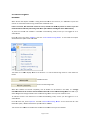
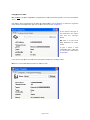
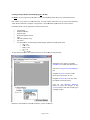
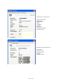
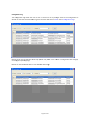
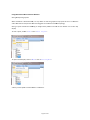
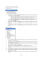
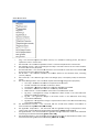
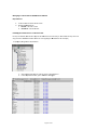
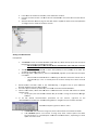
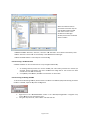
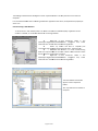
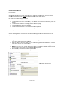
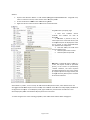
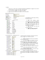
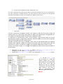
Ensure that each RF‐IOM moves to the “RF‐IOMs” category in the hierarchical display. Depending on the number of devices on the network, this may take a couple of minutes. Add all routers and RF‐IOMs to the map display by drag‐and‐drop. Note that if a device is shown in blue in the hierarchical display, it has NOT been added to the map display. This is a quick way to see which have yet to be added to the map display. Ensure all are shown as on‐line. Note that the radio network links are displayed on the map display. Ensure all links are depicted in green (good link quality) and note the LQIs (see page 45). a. If any routers or RF‐IOMs don’t show as on‐line or are not in the “Router” or “RF‐IOMs” categories in the hierarchical display, check that the PCB fuse is intact (0Ω on a multimeter) and that the correct power supply is present. b. If any router’s or RF‐IOM’s link is shown in red, check for obstructions between it and its parent, check to see that the aerial is fitted and is vertical. In the hierarchical display, right‐click on each router and RF‐IOM and select “Refresh Node Information” from the menu. This will cause the router or RF‐IOM to transmit not only its measurements, but also all its configuration data as well. NB ‐ This extra data is NOT normally transmitted, but must be requested using CMS. Where hours run is shown in italics, this denotes that a request for data has been sent to a device, but the device has not yet responded. Referencing the site survey plans, switch on all the EDs by fitting the power jumper and remount into the housing (for space housing devices). a. If this is the first time the ED has been switched on (or after replacing an EDs battery), hold down the reset button on the ED’s PCB while powering up by fitting the power jumper. This resets the battery hours run to 0. Using CMS, ensure that all the EDs appear in the hierarchical display. a. Note that initially, the EDs will be shown in the “Unknown” category in the hierarchical display. This is normal. b. Ensure that each ED moves to the “Sensor” category in the hierarchical display. Depending on the number of devices on the network, this may take several minutes. When all EDs have joined the network ‐ even if still shown in the “Unknown” category ‐ use CMS to disable auto‐commissioning mode. NB ‐ this is very important, as trying to change configuration properties while in auto‐commissioning mode may cause network errors. Add all EDs to the map display by drag‐and‐drop. Note that if a device is shown in blue in the hierarchical display, it has NOT been added to the map display. This is a quick way to see which have yet to be added to the map display. Ensure all are shown as on‐line. Note that the radio network links are displayed on the map display. Ensure all links are depicted in green and note the LQIs. a. If any EDs don’t show as on‐line or are not in the “Sensor” category in the hierarchical display, check that the correct battery is fitted, observing polarity. b. If any EDs link is shown in red, check for obstructions between it and its parent, check to see that the aerial is fitted and is vertical (for plant housing EDs) or that the housing is mounted correctly (for space housing EDs). In the hierarchical display, right‐click on each ED and select “Refresh Node Information” from the menu. This will cause the ED to transmit not only its measurements, but also its hours run and battery hours run data as well. NB ‐ This extra data is NOT normally transmitted, but must be requested using CMS. Where hours run and battery level are shown in italics, this denotes that a request for data has been sent to a device, but the device has not yet responded. When the installed network is finally formed, briefly press the receiver reset button and ensure the network reforms properly. This may take several minutes, depending on the number of network devices. When the network topology has been verified and all devices are working correctly, user configuration can begin (see pages 36 ‐ 39). Map all receiver analogue outputs needed to the required device measurements (see page 33). When configuration is complete, save the map display layout (see page 49). Generate a report of the completed network to document it for future reference (see page 50). Page 69 of 83