1
Appendix B
Test Appendix
This appendix contains the equations used to convert the output data from the sensors to units compatible with the flight simulator. This is necessary for data from the
GyroCube and the servo board.
The output from the GyroCube and the servo board cannot be send directly to the simulator. The
output is an analogue signal converted by the A/D-converter on the samplings board. This gives
a 12 bit number, which must be converted to rad/s for the gyros and m/s2 for the accelerometers.
The servo board samples the position of the servos and represents this position as a byte. This
byte is converted to an deflection angle in radians for flaps, aileron, elevator, and rudder.
Calibration of GyroCube
The output from the gyroscope is an analog signal between 0V and 5V, which are sampled by
the A/D samplings board. It is necessary make a conversion of the data from the A/D-converter.
B.0.1 Gyro
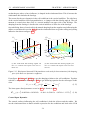
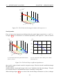
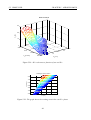
In order to convert the output from the gyro is a test performed where the GyroCube is rotated
π
rad several times around one axis. The gyroscope measures the angular velocity and this
2
output is integrated so the output are the position of the gyroscope. It is then possible to find
the factor, the output signal must be multiplied with, to convert the signal s to radians.
.
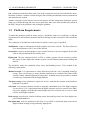
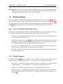
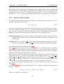
The output from the GyroCube is an analog signal between 0V and 5V, where 2,5V are 0 rad
s
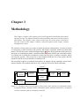
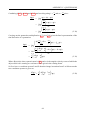
This signal is sampled with the samplings board and (B.1) describes how a bit value is converted
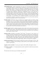
to a voltage with a bias on 2,5V. C s is found by looking at the solution and working area of the
A/D-converter on the samplings board. The samplings board has a 12 bit solution in the range
3
V
-5V to 5V, so Cbit become 210V
12 bit = 0, 0024 bit . biasdigital is 4 of the solution on the A/D-converter
and biasdigital become 3072.
90