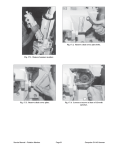
1
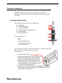
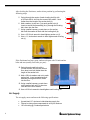
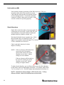
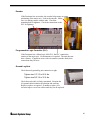
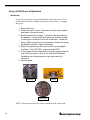
Ferris Wheel Positioner
Versa 4M, CRZ-FW
User's Manual
Important Safety Information
Genesis Systems Group is concerned with the safety and welfare of its customers and their
employees. Careful consideration has been given to the design and integration of safety
hardware and software into this system. The safety equipment is intended as a supplement
to the customer’s complete safety program for this installation. These safety precautions
are not meant to replace any related Federal, State or Municipal laws, regulations, or
guidelines pertaining to safety.
Genesis Systems Group believes that the appropriate levels of safety for an installation can
best be determined by safety professionals who are most familiar with the intended application.
It is the responsibility of the customer to insure that this level of safety is accomplished.
We recommend that each customer consult with safety professionals in order to provide a
workplace that allows for the safe application, use, and operation of this system.
For further information contact:
Genesis Systems Group
8900 North Harrison Street
Davenport, IA 52806
(563) 445-5600
Version 041307
Copyright © 2007 Genesis Systems Group, LLC
24 HOUR
HOTLINE
For a PRODUCTION machine that is DOWN
AFTER regular business hours call:
(563) 386-9693
For all other TROUBLESHOOTING and
TECHNICAL SUPPORT call:
(563) 445-5600
Regular business hours:
7:30 a.m. – 5:00 p.m. Central Time
*Please have your shop order number (SO or J #) and
your documentation readily available when
calling for assistance on your system.
Table of Contents
Positioner Installation...................................................................................... 1
Leveling and Anchoring ............................................................................. 1
Air Supply .................................................................................................. 2
Tooling Installation .......................................................................................... 3
Balancing Tool ..................................................................................... 3
1. Find Total Tool/Part Weight.............................................................. 3
2. Locate Center of Gravity .................................................................. 3
Mounting Tool ...................................................................................... 6
Positioner Control ........................................................................................... 8
Pneumatics Control ................................................................................... 8
Start-up...................................................................................................... 9
1) Check Shocks, Air, Wiring, Sweep Rotation.......................................... 9
2) Test the Sweep ................................................................................... 10
3) Adjust the Sweep ................................................................................ 11
Adjust Shocks .................................................................................... 11
Adjust Air Pressure ............................................................................ 11
System Specifications ............................................................................. 12
Start-up Troubleshooting ......................................................................... 13
Lockout/Tagout ............................................................................................. 15
Electrical............................................................................................. 15
Air....................................................................................................... 16
System ............................................................................................... 16
Shielding Gas..................................................................................... 16
Tooling ............................................................................................... 16
Maintenance ................................................................................................. 17
Before Every Shift.................................................................................... 17
Positioner ........................................................................................... 17
Air Pressure ....................................................................................... 17
Emergency stop Buttons .................................................................... 17
Weekly..................................................................................................... 18
Cable and Hoses................................................................................ 18
Axis Bearings & Locking Collars ........................................................ 18
Gearboxes.......................................................................................... 18
Ground Brush..................................................................................... 18
Roto-Ground Clamps ......................................................................... 19
Semiannually............................................................................................20
Brake ..................................................................................................20
Air Filters.............................................................................................21
Cylinders.............................................................................................22
Cam Followers ....................................................................................22
Cable carriers .....................................................................................22
Annually ...................................................................................................23
Proximity Sensors (CRZ-FW)..............................................................23
Limit switches (4M) .............................................................................24
Shock Absorbers.................................................................................24
Encoder ..............................................................................................25
Programmable Logic Controller (PLC) ................................................25
Ground Lug Nuts.................................................................................25
Every 20,000 Hours of Operation.............................................................26
Gearboxes ..........................................................................................26
Maintenance Chart ........................................................................................28
Positioner Installation
Installation of the Positioner involves leveling and anchoring the
Positioner, setting up the air supply, balancing the tooling, and mounting
the tooling.
Leveling and Anchoring
Parts supplied with system (one per anchor point):
a)
b)
c)
d)
e)
f)
leveling pad
1¼ inch leveling bolt
1½ inch leveling nut
5/8 inch anchor bolt (length varies)
7/8 inch washer
5/8 inch anchor nut
Tools supplied by user:
Level
Drill
1½ inch Socket wrench
15/16 inch Socket wrench
3 lb. Mallet hammer
f
e
d
c
b
a
To ensure proper operation, the Positioner must be level front-to-back and
side-to-side. To level the Positioner, perform the
following steps:
1. Locate all anchor holes.
2. Place a leveling pad (a) on the floor under each
anchor hole, aligning the center of each pad
with the center of each threaded anchor hole.
3. Thread a nut (c) onto each leveling bolt (b).
Thread the nut all the way up the bolt. Thread a
bolt/nut assembly (b,c) into each anchor hole
until bolt touches leveling pad (a).
4. Place a level on the Positioner at various locations and adjust the
height of each bolt (b) as necessary, until the Positioner is level
front-to-back and side-to-side.
1
After leveling the Positioner, anchor it into position by performing the
following steps:
5. Going through the center of each leveling bolt (b) with
a 5/8 inch drill bit, drill into the cement floor about 1 inch
farther than the length of the anchor bolt (d).
6. Add a washer (e) and nut (f) to each anchor bolt (d).
Insert an anchor bolt assembly (d,e,f) through the leveling
bolt, down into the floor.
7. Using a mallet hammer, pound down on the anchor
bolt until the washer is flush with the leveling bolt (d).
8. Use a 15/16 inch wrench to hand tighten anchor nut (f).
9. Use a 1 ½ inch socket wrench to hand tighten each leveling
nut (c).
f
e
c
b
a
d
If the Positioner has fence posts, anchor each post with 3/8 inch anchor
bolts and nuts (usually four holes per post):
10. Going through each hole with a
3/8 inch drill bit, drill into the cement
floor about one inch farther than the
length of the anchor bolt.
11. Add a 3/8 inch washer and nut to each
anchor bolt. Insert a washer/nut/bolt
assembly through each hole, down
into the floor.
12. Using a mallet hammer, pound down
on the anchor bolt until it is about an
Fence Post
inch above the floor bracket.
13. Use a 9/16 inch wrench to hand tighten each leveling nut.
Air Supply
The air supply must conform to the following specifications:
•
•
•
2
Unrestricted 1/2” minimum inside diameter supply line
Filtered, moisture-free compressed air at 80 psi minimum
130 cfm rating @ 2 indexes per/minute
Tooling Installation
Balancing Tool
For proper tooling installation, the tool must be balanced within
specifications. This involves:
1.
2.
3.
4.
Finding total weight of tool plus parts.
Locating center of gravity
Calculating imbalance torque
Possibly altering assembly or using counterweights.
1. Find Total Tool/Part Weight
Determine the total weight of the tool plus parts by weighing the tool/part
assembly.
2. Locate Center of Gravity
If the center of gravity for the backbone (frame), tooling, and parts to be
welded cannot be calculated easily, use the
Crane-and-Plumb-Bob method:
1. Lift the assembly using two hooks. Place
the first hook where an “A” is located, then
place the other hook at the “A” on the other
end. Lift the assembly and use a plumbbob to mark a vertical line directly below the
lifting point.
2. Set the assembly down and lift it again, but
this time use the two points marked “B”.
Again, mark a line straight down from the lifting points.
Where the two lines, A and B, intersect is the center of gravity for the
assembly in two dimensions. The third dimension does not present a
problem when dealing with Torque Imbalance and can be ignored.
Crane-and-Plumb-Bob Method
3
3. Calculate Imbalance Torque
After finding the total weight of the tool/part assembly and locating the
center of gravity, the Imbalance Torque must be calculated. The
Imbalance Torque (TI) is the product of the weight in lbs.(W), and the
distance in inches from the axis of rotation to the center of gravity (d).
Equation:
TI = W * d
Imbalanced Torque
The calculated value, TI , must be less than 600 in-lbs. If it is not, the
tooling and backbone need to be altered so the center of gravity moves
closer to the axis of rotation. Another solution is to balance the setup
using counterweights to move the center of gravity.
Needs Balancing
4
4. Alter Assembly or Use Counterweights
Alter Assembly
If the tooling, backbone, and objects to be welded are adjusted to change
the center of gravity, recheck the center of gravity using the Crane-andPlumb-Bob method. Then recalculate TI. If TI is less than 600 in-lbs,
further alteration is not needed. If TI is too large, continue to alter the
assembly or consider using counterweights.
Use Counterweights
Counterweights can be used to alter an assembly’s center of gravity. If the
center of gravity lies at (X, Y) from the axis of rotation, then the assembly
must be balanced so that TI < 600 in-lbs. The easiest way to do this is to
determine the weight acting at point (X, Y), then place a counterbalance of
the same weight at point (-X, -Y). This will result in a balanced assembly.
Also, if the weight needed at (-X, -Y) is too great, doubling the distance
(-2X, -2Y) will allow the counterbalance weight to be halved.
Balanced Assembly
IMPORTANT!: If counterweights are used, they must remain inside
the Swing Radius.
If a counterweight is used to alter the center of gravity, recheck the center
of gravity using the Crane-and-Plumb-Bob method. Then recalculate TI.
If TI is less than 600 in-lbs, further alteration is not needed. Make sure W
includes the counterbalance weight. Also, make sure the gearbox has a
high enough value.
5
Mounting Tool
In a standard minor axis tooling installation, with a bearing at the tailstock
end, the headstock end remains fixed while the tailstock bearing is simply
supported. This allows the tooling shaft to move axially as the tooling
deflects and pivots about the bearing.
To maintain structural integrity required of the Positioner, certain tooling
specifications must be met.
Gearbox Mounting Plate
Tooling mounting plates must mate with gearbox faceplates provided by
Genesis Systems Group.
6
Gearbox Faceplate
Each RV gearbox faceplate conforms to the specifications shown in the
following diagram.
NOTE: Tooling should be mounted with ½ -13 grade 8 bolts and
torqued to SAE standards.
Gearbox Faceplate for RV Gearbox
7
Positioner Control
The Positioner is a system of components that work together to rotate an
axis between a load area and a robot area. The axis has two sides, A and
B. The components include two pneumatic cylinders, an air package,
proximity sensors or limit switches, shock absorbers, and a brake.
Refer to the Plug and Play Manual for control setup, programming, and
operation.
Pneumatics Control
The pneumatic valve assembly is mounted inside the cylinder enclosure, at
the headstock end of the workcell. Refer to electrical schematics for
wiring.
Air Lines
to Cylinders
Brake Pressure
Sensor
Cylinder 1 Valve
Brake Valve
Assembly
Cylinder 2 Valve
Air Pressure
Sensor
Cylinder Pressure
Regulator
•
•
•
8
Unrestricted 1/2” minimum inside diameter supply line
Filtered, moisture-free compressed air at 80 psi minimum
130 cfm rating @ 2 indexes per/minute
Brake Air
Filter
Start-up
The Positioner's components must be checked, tested, and possibly
adjusted before operations are started. Perform the following steps:
1) Check Shocks, Air, Wiring, Sweep Rotation
Before applying power to the system, complete the following tasks:
1. Make sure shock stiffness is at the setting indicated in the
System Specifications table.
2. Make sure air pressure is at the setting indicated in the
System Specifications table.
3. Make sure all air lines are tightened and are not in the
motion area.
WARNING!
Step 4 could result in unexpected motion of the sweep. Do step 4 only if both tools A and
B are mounted, or both tools A and B are removed. Gradual motion is expected, but if
dramatic movement results, the tooling should be checked for balance. Failure to keep
the area clear of people and objects could result in serious injury or even death!
4. Make sure the sweep area is clear, then manually override
the brake directional valve. With the brake released, rotate
the sweep by hand to check clearances.
9
2) Test the Sweep
After checking the shocks, air, wiring, and sweep clearances, perform the
following steps to test the sweep:
WARNING!
Before performing the following steps, make sure the sweep area and actuating area are
clear of people and objects. Failure to keep these areas clear of people and objects
could result in serious injury or even death!
1. Make sure the sweep and actuating areas are safe and
secure. This should include, but not be limited to, robots
clear of sweep, all gates closed, light curtains are functional,
and headstock doors are closed or marked as dangerous.
2. Make sure the Emergency stop buttons are functional.
3. Initiate the sweep.
If an error occurs, refer to Start-up Troubleshooting.
The axis should sweep in one smooth, continuous motion. If necessary,
make adjustments to the shocks and air pressure. For a system with
balanced tooling within the recommended ranges, these external
adjustments should be all that is necessary to make the sweep function
properly.
For a system with maximum tool weight or unbalanced weights, it may be
necessary to adjust parameter values, but first attempt to compensate by
adjusting the shocks and air pressure. After making changes to parameters
it may be necessary to adjust the shocks and air pressure again.
10
3) Adjust the Sweep
Adjust Shocks
If motion is abruptly reduced or reversed when the sweep contacts the
shock, reduce the stiffness of the shock by increasing the setting value.
Increase the setting in half number increments only. Finer adjustments
may be necessary for final adjustment.
If the sweep bounces when it contacts the hard-stop, increase the stiffness
of the shock by decreasing the setting value. Decrease the setting in half
number increments only. Finer adjustments may be necessary for final
adjustment.
IMPORTANT!: Do NOT adjust shock
setting to less than 2. If setting is less
than 2, shock life decreases dramatically.
NOTE: Adjustment settings apply to ACE shocks only. If using different
shocks, check the manufacturer's instructions.
Adjust Air Pressure
Air pressure adjustment is not normally necessary but may be required in
certain applications. If adjusting air pressure, refer to the System
Specifications table for maximum and minimum allowable pressure
settings, and note the following guidelines:
Increasing air pressure increases the sweep speed but it also increases the
effect of the slowdown. Adjust air pressure in 5 psi increments.
Decreasing air pressure decreases the sweep speed but it also decreases the
effect of the slowdown. Adjust air pressure in 5 psi decrements.
Air pressure adjustment also affects brake operation. If air pressure is too
low (below 80 psi), the brake will drag on the brake disk, slow the speed
of the table, and increase wear on the brake pads.
11
System Specifications
CRZ-FW
V4-42
V4-54
V4-60
3.5 sec.
4 sec.
5.5 sec.
9 sec.
42”
42”
54”
60”
1m 1.5m 2m
84” 96” 120”
96" 120" 144"
Maximum Tool Weight (Per Side)
1200 lbs.
3000 lbs.
5000 lbs.
5000 lbs.
Maximum Tool Imbalance (Rotational)
600in/lbs
600in/lbs
600in/lbs
600in/lbs
50 lbs.
150 lbs.
150 lbs.
150 lbs.
Maximum Air Pressure
90 psi.
90 psi.
90 psi.
90 psi.
Minimum Air Pressure
50 psi.
35 psi.
35 psi.
35 psi.
Recommended Air Pressure Setting
80 psi.
70 psi.
60 psi.
50 psi.
6
3.5
3
4
2 turns out
n/a
2 turns out
1½ turns out
ACOUNT_PRESET
570
700
700
700
BCOUNT_PRESET
100
100
100
100
DZ1L
200
230
230
230
DZ1H
325
395
395
395
DZ2L
345
405
405
405
DZ2H
470
570
570
570
AMAX_START
30
30
18
17
AMIN_START
20
20
13
8
AMAX_END
11
15
8
7
AMIN_END
5
8
2
2
BMAX_START
30
30
18
17
BMIN_START
20
20
13
8
BMAX_END
11
15
8
7
Capacities
Exchange Speed
Maximum Tool Diameter
Available Tool Lengths
Maximum Imbalance Between Tool A and B
External Adjustment
Initial Shock Absorber Setting
Flow Control Setting
Software Parameters
BMIN_END
12
5
8
2
2
SLOWDN_SIZE
230
300
300
450
RECOVER_MAX
8
16
8
7
RECOVER_MIN
3
5
4
2
Maximum MAX_START Value
35
45
35
35
Start-up Troubleshooting
Problem
Probable Cause
Action
Abnormal Sweep Stop
(Plug 'N Play error)
Sweep was not in position
when control power was
turned on. Undefined
condition stopped sweep.
Recover sweep to Side A or B.
Air Pressure Below Recommended PSI
Air supply shut off valve
closed. User air supply
insufficient. Improperly
adjusted or faulty regulator.
Improperly adjusted or faulty
pressure switch.
Check status of shut-off valve. Check user air
supply. Check functionality of regulator. Check
functionality of pressure switch
Brake Release Fuse Blown
(Plug 'N Play error)
Fuse is bad or wiring is faulty.
Check fuse and wiring. See electrical schematics
for your system.
Brake Pressure Errors
(Plug 'N Play error)
Brake pressure not present
while output off.
Verify both brake solenoids are acting at same
time. Check for main air pressure.
Brake pressure present while
output on.
Control Power is Off
System E-stopped or faulty
wiring.
Check status of E-string and wiring.
Extend Cylinder #1 Fuse Blown
(Plug 'N Play error)
Fuse is bad or wiring is faulty.
Check fuse and wiring. See electrical schematics
for your system.
Extend Cylinder #2 Fuse Blown
(Plug 'N Play error)
Fuse is bad or wiring is faulty.
Check fuse and wiring. See electrical schematics
for your system.
Possible A at Robot Proximity Sensor Failure
Faulty proximity sensor or
wiring.
Check functionality of proximity sensor. Check
wiring. See electrical schematics for your system.
Possible B at Robot Proximity Sensor Failure
Faulty proximity sensor or
wiring.
Check functionality of proximity sensor. Check
wiring. See electrical schematics for your system.
Possible Encoder Malfunction
(Plug 'N Play error)
Encoder wheel not contacting
actuator arm. Encoder
channels A and B reversed.
Faulty wiring. Pull-up
resistors not functioning.
Make sure wheel is contacting actuator arm.
Manually move encoder wheel back and forth
while monitoring inputs 0 and 1 on PLC. If Inputs
do not flicker when wheel is moved check wiring.
See electrical schematics for your system.
Retract Cylinder #1 Fuse Blown
(Plug 'N Play error)
Fuse is bad or wiring is faulty.
Check fuse and wiring. See electrical schematics
for your system.
Retract Cylinder #2 Fuse Blown
(Plug 'N Play error)
Fuse is bad or wiring is faulty.
Check fuse and wiring. See electrical schematics
for your system.
13
Start-up Troubleshooting (continued)
14
Problem
Probable Cause
Action
Sweep stops just after leaving hard-stop.
Encoder signals reversed.
Sweep Position value out of
range (Plug 'N Play error).
Safety circuit problem.
Check wiring of inputs 0 and 1. Recover sweep to
either Side A or B and cycle control power. This
will reinitialize the position count.
E-STOP occurs as soon as sweep begins.
Light curtain blocked or
malfunctioning. Gate safety
contact faulty. Faulty wiring
in E-String. Safety circuit
problem.
Test functionality of light curtain and gates or
other safety device associated with sweep
protection. Check user wiring.
Sweep hesitates mid sweep.
Directional valves controlling
wrong cylinder. Brake drag.
Check valve wiring. See electrical schematics for
your system. Check pneumatic plumbing. Check
air pressure.
Sweep strikes hard-stop harshly
bounces in both directions of sweep.
and
Shocks stiffness too low.
Tool imbalance too great for
current parameter settings.
Air pressure not sufficient for
full slowing power.
Check shock settings.
Replace shock if
adjustments do not change characteristics of
shock.
Adjust parameter settings.
Check
regulator setting.
Sweep strikes hard-stop harshly
bounces in only one sweep direction.
and
Shock stiffness too low.
Directional valve not able to
apply retract pressure. Tool
balance too great for current
parameter settings.
Check shock settings.
Replace shock if
adjustments do not change characteristics of
shock. Check functionality of directional valves to
see if condition has been caused by a faulty coil
on retract side of valve. This would also make the
beginning of the sweep slower than normal but
the sweep would still complete. Adjust parameter
settings.
Sweep comes to complete stop before
reaching hard-stop and then completes
sweep.
Shock stiffness too high.
Sweep MAX_END parameter
too low. Air pressure too
high.
Check shock. Replace shock if adjustments do
not change characteristics of shock.
Adjust
parameter settings. Check regulator setting.
Sweep comes to complete stop or reverses
direction before reaching hard-stop and then
slams into hard top with bouncing.
Sweep MAX parameter
slowdown slope too
aggressive. Sweep
MIN_END parameter may be
too high.
Adjust parameter settings. .
Lockout/Tagout
Only trained personnel should perform maintenance. The following
lockout/tagout procedures should be followed before performing any
maintenance. In addition to these procedures, other practices may be
needed. It is the responsibility of the customer to consult safety
professionals to determine and apply the best safety practices.
WARNING!
Before performing any maintenance, use lockout/tagout
procedures to prevent system operation. Failure to prevent
operation could result in serious injury or even death!
Electrical
To prevent electrical power to the system from being turned on:
1. Turn the main enclosure's main disconnect to OFF.
2. Secure knife switch with a lockout/tagout device and
padlock.
WARNING!
Lethal voltage is present in the enclosure whenever it is
connected to a power source. Be extremely careful to
avoid electrical shock.
Turning the disconnect or knife switch to OFF removes
power from the output side of the device only. High
voltage is always present at the input side whenever the
enclosure is connected to a power source.
15
Air
To prevent system air from being turned on:
1. Push the blocking valve down.
2. Secure valve with a lockout/tagout device
and padlock.
System
To prevent system operation, press an E-stop button:
Shielding Gas
At the user supplied valve, turn off the shielding gas before
performing any maintenance.
Tooling
Make sure all parts are removed.
16
Maintenance
Proper maintenance of the Positioner is essential for maintaining its
optimum operating condition. Perform maintenance according to the
schedules recommended in this manual. Also, refer to component
manufacturers’ documentation for additional maintenance instructions.
Before Every Shift
Positioner
Clean the positioner and remove any objects that are not needed for safe
operation of the system. Remove excessive spatter and dust build-up on
the work surfaces.
Air Pressure
Check air pressure. Make sure it is 80 – 100 psi.
Emergency stop Buttons
Check that every E-stop button stops table rotation.
17
Weekly
Cable and Hoses
Check all external cables and flexible hoses for damage. Check hoses for
abrasion, cracking, kinks and burns. Repair or replace as required, being
careful to reroute hoses properly.
Pillow Block Bearings
Axis Bearings & Locking Collars
Pillow block bearings are located at the tailstock
ends of the axes. These bearings are greased before
being shipped. They do not require any further
lubrication or maintenance. Make sure the locking
collars are tight.
Locking Collars
Gearboxes
A servo driven gearbox is located at the head of each minor axis. These
gearboxes are greased before being shipped. They do not require further
lubrication except for changing the grease every 20,000 hours of
operation. They should be inspected for leaks. Check for fluid on the
underside of the gearbox and faceplate, and on the floor. If a unit is
leaking, call Genesis Systems Group.
Ground Brush
A ground brush may be located at the end of each minor axis.
Once a week, lubricate each brush. To lubricate, pull back on
the copper unit. Cover the entire
surface of the copper unit (wherever
it comes in contact with the axis)
with a thin coat of 'Tweco Electrical
Joint Compound and Lubricant'.
Replace ground
brush when this
distance is less
than 24 mm
(.93 inches)
18
Roto-Ground Clamps
Roto-Ground clamps may be located at the end of each minor axis. The
units are lubricated before being shipped. Once a week, turn the cap one
full turn (360º). Turning the cap forces lubricant into the unit. When the
cap is fully screwed down (can no longer be turned), then add lubricant.
To add lubricant, perform the following steps:
1. Remove the cap.
2. Fill the funnel and cap with 'Tweco
Electrical Joint Compound and Lubricant'.
Cap
3. Screw the cap back on, turning only until
resistance is felt.
Make sure roto-ground is
tight on the tailstock shaft
(torqued to 90 ft.-lbs.).
Make sure unit makes
firm contact with shaft yet
is able to rotate. Handtighten bolt with wrench
(snug), then back off 1/4
turn.
Funnel
19
Semiannually
Brake
IMPORTANT!: Make sure the air supply to the system is OFF.
WARNING!
Perform brake maintenance every six months. Failure to
perform maintenance could lead to brake malfunction, and
possibly cause serious injury or death!
Brake Cover (Housing)
Carefully remove the brake cover
(housing). It is
attached to the air
bag and to hoses.
Remove the cover
by removing the
two mounting
bolts.
Brake Disk
Left Brake Pad
Right Brake Pad
Pivot Bolt
Left Actuator
Right Actuator
Actuators
With the air supply to the brake OFF, make sure the
left and right actuators are parallel to each other. If
± 1/8”
they are not parallel, adjust them using the brake's
two pivot bolts.
IMPORTANT! The actuators must
Brake Pads
Check brake pads for wear. If pads are less than
1/8th inch thick, replace them.
be parallel to each other. Measure
from the inside of the left actuator,
to the inside of the right actuator (in
two places), making sure
measurements are within ± 1/8
inch of each other.
Air Bag
Check the air bag and air valve for leaks by looking
(with safety glasses on) and listening. Control power
must be on.
Pivot Bolts
Muffler
Use only a clean UCI MHC-3 or NUMATICS
M3MN muffler on the brake's air bag.
Muffler
UCI MHC-3
Air Bag
NUMATICS M3MN
Air Valve
20
Air Filters
Brake
Every six months, inspect the brake air filter. If the filter is discolored
(not white), replace it with the same type and brand.
WARNING!
Inspect the brake air filter every six months. Failure to
perform maintenance could lead to brake malfunction, and
possibly cause serious injury or death!
System
Every six months, inspect the system air filter. It is located either near the
peripheral equipment or in the headstock enclosure. Look through the
sight glass. If the unit is dirty, disassemble and clean it, or
replace it.
21
Cylinders
The two cylinders at the headstock end of the major axis have three grease
fittings. Give each fitting one pump of a high-quality lithium based NLGI
#2 or #3 bearing grease.
Cam Followers
The system has three cam followers at the headstock end. Give each cam
follower one pump of a high-quality lithium based NLGI #2 or #3 bearing
grease. Make sure the top cam
Shims
follower is making contact with the
tube.
Cable carriers
Cam Follower
An energy chain (cable carrier) may be mounted at the
headstock end of each minor axis. It carries the power
cabling. If the Positioner has an energy chain, visually
inspect it. Look for cracked or separated links. Replace
if necessary. Make sure all fasteners are tight.
22
Tube
Annually
Proximity Sensors (CRZ-FW)
Proximity sensors (proxes) help ensure accurate positioning of the
CRZ-FW's major axis. Proxes are located near the
shock absorbers.
Check each proximity sensor for tightness and proper
distance from its target. The distance should be such
that the LED lights up but the prox does not touch its
target. Jam nuts and prox bracket should be firmly
tightened. Prox brackets should be fastened with lock
nuts/washers and a removable thread locker if
necessary. Examine prox cables for abrasion, cracks
and burns. Replace as needed, using care when
rerouting cables. Hand tighten cable plugs to proxes,
being careful to not overtighten. If necessary, wipe
proxes with a clean, dry cloth.
IMPORTANT!
Proper alignment of proximity sensors is
essential for operations. Use care not to bump
or move them. NEVER step on, or set
anything on, a sensor or its bracket.
23
Limit switches (4M)
Limit switches monitor positioning of the 4M's major axis. They are
located on either side of the major axis (sweep).
Check that the limit switches are fastened securely
to the mounting brackets. Check that each cable
connector is firmly connected to its switch. Make
sure the switches are operating properly.
Shock Absorbers
On the 4M, a shock absorber is located on each side
of the major axis (two total). On the CRZ-FW, two
shock absorbers are located inside the headstock
module (with the cylinders, encoder, etc.)
Each shock absorber has two spanner nuts. Check
that all spanner nuts are fastened securely. To
tighten, use a spanner wrench and apply 75 to 100 lbs
of force with about one foot-lever.
Check each shock absorber for leaks.
Replace if leaking.
NOTE: If the axis bounces off the hard rest
stop at the end of its rotation
(noisier than normal), the shock
absorbers are too loose. Adjust
setting to a lower number.
If the axis bounces off the shock at
the end of its rotation, the shock
absorbers are too stiff. Adjust
setting to a higher number.
To adjust shock absorbers, use an Allen wrench to turn the dial, adjusting
(at the most) to the next half number increment. For example, adjust from
3 to 3½ or from 3 to 2½. DO NOT adjust shock absorbers to less than 1½.
NOTE: Adjustment settings apply to ACE shocks only. If using
different shocks, check the manufacturer's instructions.
24
Encoder
If the Positioner has an encoder, the encoder helps ensure accurate
positioning of the major axis. Look at the encoder. Make
sure it is making contact with the tube. Check the
mounting bolt for tightness. Check the connections to the
PLC for tightness.
Programmable Logic Controller (PLC)
If the Positioner has a MicroLogix 1000 PLC, the PLC controls the
rotation of the major axis. No maintenance is required. The unit does not
have a battery. If problems occur with axis rotation (encoder fault), then
connections may be loose.
Ground Lug Nuts
Check that each ground lug nut connection is tight.
Tighten size 1/2"-13 to 80 ft.-lbs.
Tighten size 3/8"-16 to 32 ft.-lbs.
Check that each cable is firmly terminated. Examine the
4/0 ground cable insulation for abrasion and cracking.
Repair or replace as required. If unable to replace, use
electrical tape to cover bare cables until they can be replaced.
25
Every 20,000 Hours of Operation
Gearboxes
A servo driven gearbox is located at the head of each minor axis. Every
20,000 hours of run time, change the grease in each gearbox. To change
the grease:
1. Remove the tool.
2. Rotate the axis for about 15 minutes to warm up the grease
and make it flow more easily.
3. Each gearbox has two plugs. Locations vary depending on
the gearbox. It may be that both plugs are on the front side,
or one plug is on the front and one on the back. Locate the
plugs. Make sure the axis is positioned so that the two plugs
are aligned vertically. Remove the plugs.
4. Siphon the grease from the lower hole into an acceptable
container. Use CAUTION – grease may be HOT!
5. Pump grease into the lower hole so that the grease works its
way up into the gears. Refer to the Gearbox Lubrication
Quantities chart to determine the type and quantity of
lubrication.
6. Replace plugs.
Horizontal
Vertical
Center shaft
NOTE: Horizontal/vertical refers to the orientation of the center shaft.
26
Gearbox Lubrication Quantities
MAKE
MODEL
LUBRICANT
APPLICATION
QUANTITY
(pints)
SUMITOMO
F2C-T35
OPTIMUM LONGTIME PD0
HORIZONTAL
.40
SUMITOMO
F2C-T35
OPTIMUM LONGTIME PD0
VERTICAL
.51
SUMITOMO
F2C-T45
OPTIMUM LONGTIME PD0
HORIZONTAL
.53
SUMITOMO
F2C-T45
OPTIMUM LONGTIME PD0
VERTICAL
.66
SUMITOMO
F2C-T65
OPTIMUM LONGTIME PD0
HORIZONTAL
1.24
SUMITOMO
F2C-T65
OPTIMUM LONGTIME PD0
VERTICAL
1.54
Nabtesco
RV-40E
MOLYWHITE RE00
HORIZONTAL
.41
Nabtesco
RV-40E
MOLYWHITE RE00
VERTICAL
.5
Nabtesco
RV-80E
MOLYWHITE RE00
HORIZONTAL
.81
Nabtesco
RV-80E
MOLYWHITE RE00
VERTICAL
.97
Nabtesco
RV-110E
MOLYWHITE RE00
HORIZONTAL
.91
Nabtesco
RV-110E
MOLYWHITE RE00
VERTICAL
1.1
Nabtesco
RV-320C
Greased and sealed by manufacturer – no change of grease req'd
Nabtesco
RV-320E
MOLYWHITE RE00
HORIZONTAL
2.2
Nabtesco
RV-320E
MOLYWHITE RE00
VERTICAL
2.6
Nabtesco
RV-320EL
MOLYWHITE RE00
HORIZONTAL
6.97
Nabtesco
RV-320EL
MOLYWHITE RE00
VERTICAL
5.71
Nabtesco
RV-450E
MOLYWHITE RE00
HORIZONTAL
3.37
Nabtesco
RV-450E
MOLYWHITE RE00
VERTICAL
4.06
Nabtesco
RV-700EL
MOLYWHITE RE00
HORIZONTAL
10.88
Nabtesco
RV-700EL
MOLYWHITE RE00
VERTICAL
13.1
Nabtesco
RV-900C
MOLYWHITE RE00
HORIZONTAL
14.8
Nabtesco
RV-900C
MOLYWHITE RE00
VERTICAL
15.4
Nabtesco
GH7
MOLYWHITE RE00
HORIZONTAL
.275
Nabtesco
GH7
MOLYWHITE RE00
VERTICAL
.254
Nabtesco
GH17
MOLYWHITE RE00
HORIZONTAL
.623
Nabtesco
GH17
MOLYWHITE RE00
VERTICAL
.602
Nabtesco
GH24
MOLYWHITE RE00
HORIZONTAL
.634
Nabtesco
GH24
MOLYWHITE RE00
VERTICAL
.634
Nabtesco
GH40
MOLYWHITE RE00
HORIZONTAL
1.638
Nabtesco
GH40
MOLYWHITE RE00
VERTICAL
1.257
Nabtesco
GH100
MOLYWHITE RE00
HORIZONTAL
3.886
Nabtesco
GH100
MOLYWHITE RE00
VERTICAL
N/A
27
Maintenance Chart
Use this chart as a reference for doing maintenance and to record the dates
when maintenance is done. Also, refer to the component manufacturers’
documentation for additional maintenance instructions.
- check
L - lubricate
Before
Every Shift
Weekly
Every
Six Months
+ - clean
Positioner
Annually
Every
20,000
Hours
+
Air pressure
E-stop buttons
Cables & hoses
Locking collars
Ground brush
Roto-ground
L
L
Brake
Air filters
Cylinders
L
Cam followers
Cable carriers
Proximity sensors
Limit switches
Shock absorbers
Encoder
Ground lug nuts
Gearboxes
28
L-change
Index
actuators ..............................20
air ...........................8, 9, 11, 16
air bag ..................................20
air filter .............................8, 21
air pressure ..........................17
air valve................................20
anchor ....................................2
main enclosure .................... 15
maintenance ........................ 17
muffler.................................. 20
nuts ................................ 23, 25
bearings ...............................18
brake ................................8, 20
brush ....................................18
PLC...................................... 25
pneumatics ............................ 8
positioner ............................. 17
posts ...................................... 2
proximity sensors................. 23
psi .................................. 11, 17
cable carrier .........................22
cables.............................18, 24
cam followers .......................22
clamps..................................19
counterweight.........................5
cylinders ...........................8, 22
regulator................................. 8
roto-ground clamps.............. 19
electrical ...............................15
Emergency Stop...................16
encoder ................................25
energy chain.........................22
E-stop buttons ......................17
faceplate.................................6
fence posts.............................2
filter ........................................8
fittings...................................22
gas .......................................16
gearboxes ..................6, 18, 26
ground brush ........................18
ground lug nut ......................25
shock absorbers ............ 11, 24
shocks.................................... 9
side A, B ................................ 8
start-up................................... 9
sweep .............................. 9, 10
switches ............................... 24
tooling .................................. 16
tooling balance....................... 3
tooling mounting plate............ 6
torque..................................... 4
troubleshoot ......................... 13
valve .................................... 20
valves..................................... 8
wiring ..................................... 9
hoses....................................18
level........................................1
limit switches ........................24
locking collars.......................18
lockout/tagout.......................15
lubrication...........18, 19, 22, 26
i