1
7/15
TP20316,Rev.2
Chevrolet Equinox
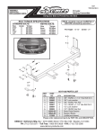
BOlT TORQuE SPECIfICATIONS
STANDARD BOlTS:
Size
5/16”
3/8”
7/16”
1/2”
grade
5
5
5
5
mETRIC BOlTS:
Torque
20 ft/lbs.
35 ft/lbs.
56 ft/lbs.
85 ft/lbs.
Size
8mm
10mm
12mm
14mm
Torque
22 ft/lbs.
42 ft/lbs.
70 ft/lbs.
95 ft/lbs.
Pin height - 14-3/4”
Centers - 24-1/4”
,7(0
5(9
(&1
'$7(
')70
$
'.<
25.
$
$
$
ef. Part
R
No. No.
1. 00057
2. 00059
3. 00060
4. 00061
5. 00084
6. 00214
7. 00907
8. 00908
9. 00967
10. 04055
11. 07286
12. 09032
,7(0
3$57
'(6&5,37,21
47<
1&;*'+(;
:$6+(5635,1*/2&.
3OXJ0RXQW
1871&+(;
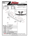
9518316 parts list
3$57
:$6+(5
:$6+(5)/$
/2&.:
+(;18
/2&.:$
:$6+(5)/$
%2/71&
%2/71
%2/71&
1&;
:$6+(563
187PP
:$6+(5)(
%2/71&
)/$1*(
%$6(3/$7(3
%$6(3/$7(3
&URVVPHPE
723%5$&.(
ef. Part
R
/2:(5%5$
$
Qty. Description
No.
No.
Qty. Description
187675,3
2 1/4” Lock Washer
13. 09228
8 8mm Fender Washer
%86+,1*
8 3/8” Flat Washer
14. 11557
4 3/8” - NC x 1 - 1/4” Hex Flange
Bolt
Gr.5 %2/700
24 3/8” Lock Washer
15. 12979
1 Pull Ear Cover “A”
%5$&(3$66
24 3/8” NC Hex Nut
16. 12980
1 Pull Ear Cover “B”
%5$&('5,9
'$7(
'5$:1%<
2 1/2” Flat Washer
17. 13565-357+,5'$1*/(
1 Crossmember
f/Chevy
5:Equinox
'(6&5,37,21
%$6(3/$7(
'$7(
$3329%<
2 1/4” Flat Washer
18. 14030-35352-(&7,21
2 Top Bracket
5(
'$7(
16 3/8”-NC x 1” Hex Bolt Gr. 5
19.
14031-35
2
Lower
Bracket
6$9('%<
'5$:,1*12
81/(6627+(5:,6(
7+6732%2;
5:
63(&,),('$//',0(16,216
$5(,1,1&+(6
4 3/8”-NC x 1-3/4” Hex Bolt Gr. 5 %2<'(1,2:$
20. 14589-35 2
Nut Strip
72/(5$1&(6
:(,*+7
; 0,10$&+,1(685)$&(
2 1/2”-NC x 1-1/2” Hex Bolt Gr. 5 7+('5$:,1*$1'$//
21. 14592-95
4 Bushing
,1)250$7,217+(5(
;; %5($.$//6+$53('*(6
21$5(7+(3523(57<2)
92/80(
6&$/(
2 1/4”-NC x 1” Hex Bolt Gr. 5
22.
4 8mm-1.25
x 50mm
Hex Bolt Gr. 8.8
'(0&2 14593
%(1'$1''5$)7
;;;
8 8mm Lock Washer
23. 14978-35 1 Brace Passenger Side
4 8mm-1.25 Hex Nut
24. 14979-35 1 Brace Driver Side
25.
5937
1 Plug Mount Kit
Please order replacement parts by PART NO.
26. 12329
3 Loctite (not shown)
and DESCRIPTION.
27. 14329
1 3/8” Fish Wire
'5$:1%<
(1*$3329
7+6732%2;
%2<'(1,2:$
7+('5$:,1*$1'$//
,1)250$7,217+(5(
21$5(7+(3523(57<2)
'(0&2
'.<
-.
'$7(
'$7(
81/(6627+(5:,6(
63(&,),('$//',0(16,216 7+,5'$1*/(
352-(&7,21
$5(,1,1&+(6
'(6&5,37,21
SOXJPRXQW
'5$:,1*12
5(9
72/(5$1&(6
; 0,10$&+,1(685)$&(
;; %5($.$//6+$53('*(6
;;; %(1'$1''5$)7
6&$/(
6+((72)
Doing Our Best to Provide You the Best
WARRANTY POLICY & REGISTRATION
Go online to www.demco-products.com to review Demco warranty policies and register your Demco product.
Warning: Failure to follow these instructions can result in loss of towing vehicle control, separation
of the tow BAR from the towing vehicle, separation of the towed vehicle from the tow BAR, causing severe personal injury, death, or property damage.
CAUTION
Safety is of utmost importance at all times. There are several items that
must be checked each time before using and while using a tow bar.
Before allowing anyone to hook up or operate a tow bar, be sure they
have read and understand the proper operating procedure.
DO NOT use worn or damaged cables and/or pins.
Be sure the SAFETY CABLES are hooked, chassis to chassis, to both
the towing and towed vehicles using the crisscross method.
Check clearance between vehicles in a turning situation.
Check base plate mounting bolts for tightness and frame for metal fatigue.
Do not load the towed vehicle with anything as you may exceed the
towing capacity of the tow bar.
important installation items
DEMCO products and accessories are intended to be
installed by professional installers with experience,
proper equipment and the ability to do modification
work. Installers with these qualifications can be
found in RV and Automotive Service Centers.
If the car to be towed has been in an accident, the
chassis may be damaged in an area where the Base
Plate attaches. It may no longer be suitable for towing. Extreme caution and careful examination are
required in such a situation. It is also likely, even
from a minor accident, that the hole alignment will
be more difficult due to hole alignment problems.
Keep fingers away from pivot points to prevent personal injury.
Be sure the steering components of the towed vehicle are properly
aligned.
NOTE: This unit can be backed up in moderate increments. Any severe backwards cornering could result in damage to the Tow Bar and/
or towed vehicle chassis.
For automatic transmissions: Consult your vehicle owners manual
for towing suitability with the drive shaft connected. Otherwise, the
towed vehicle will have to be equipped with a transmission pump or
drive shaft disconnect.
Check to make sure that all lights are in proper working order.
The information on towability of vehicles is reprinted with permission of MotorHome© Magazine, and is believed to be reliable. However,
Demco does not warrant the information to be correct. Always consult
your towed vehicle owner’s manual and follow towing instructions. Each
year, MotorHome© Magazine, compiles a list of vehicles that can be
towed four-down behind a motorhome with no modifications required.
This guide contains only those vehicles that have been approved by
their manufacturers for towing.
Caution: MotorHome© Magazine left out any vehicles that have
towing speed limits slower than 55 m.p.h., or distance limits of less than
200 miles. At a minimum, these vehicles require significant modification, such as the use of an aftermarket product, to make them towable.
The availability of a Demco Tow Bar Base Plate does not imply that
these vehicles can be modified or that there is an aftermarket product
available. Refer to your vehicle owner’s manual or consult your dealer
to determine whether your vehicle can be modified to make it towable.
Failure to observe this precaution could result in property damage or
personal injury.
Many DEMCO Base Plates are designed to use
existing holes and hardware to mount the Base Plate
to the towed vehicle. Even though the bolt is there,
however, do not assume it is adequate for mounting
the Base Plate. Manufacturers make many changes
in hardware both within and between model years.
Be sure the bolt is long enough to protrude past
the nut a distance no less than 1/2 the diameter
of the bolt, after the Base Plate is mounted. The
threads should be in good condition. We require
that “
Blue” be used on all bolts. If a
new bolt is required, be sure it is SAE Grade 5 or
Metric 8.8.
NOTE: The dimensional variations between otherwise
identical vehicles can be considerable. Some minor modifications may have to be made to ensure
a proper fit.
installation instructions
1. Open hood and remove 6 plastic push fasteners and 4
screws from the panel on top of the grill. Remove center
plastic cover and hinge outer covers up and back. Lift
outer panel to allow grill to be free.
5. If Equipped Remove the cooler from the bottom of the
bumper and let hang. Note: bolts will not be reused.
2. Remove two plastic push fasteners and three screws
in the front of each fender well.
3. Remove two screws from the bottom of the facia on each
side. Pull out firmly on outer corner of facia from the front
of the fender and remove facia.
4. With a pliers pinch tabs that hold the wiring harness to
the back of the bumper and let hang.
6. Remove four bolts from each side of the bumper and
set bumper to the side. NOTE: If only three factory
bolts are used take factory bolt and use it to tap top
inside hole. Then use baseplate as jig to drill hole in
bumper to allow bolt to pass through.
7. Remove four bolts from support bracket on driver side
and remove. Bracket and bolts will not be reused.
8. With and assistant mount the baseplate into place with
the bumper bolts.
11. Cut frame below baseplate on each side as shown in
picture.
9. Drill two 13/32” holes using the baseplate as a template
on each sides.
12. Clamp lower bracket to frame as shown. Make sure
bracket is flush with bottom of pinch weld. Drill four
13/32” holes using bracket as a template. Repeat on
other side.
10. Place 3/8 x 1-3/4” with 3/8” flat washers thru drilled
holes and place 3/8” flat washer, the 3/8” lock washer
and 3/8” nut behind the bumper mount. NOTE: Use
blue
on all bolts and tighten all bolts according to chart on front page. Minor trimming of the
bumper may be required to let the washers in the front
Lay flat against the baseplate.
13. Place 3/8 x 1” bolts thru drilled holes and place 3/8”
lock washer and 3/8” nut behind frame. NOTE: Use
blue
on all bolts and tighten all bolts according to chart on front page.
14. Remove three screws from the top of headlight assembly
and two from the side (as shown in inserted picture).
Pull headlight out and rest on engine. NOTE: Some
headlights have a hidden tab holding light to fender.
Headlight is removed for ease of drilling.
17. Clamp upper bracket to frame as shown. Make sure
bracket is flush with the pinch weld on the side. Drill
four 13/32” holes using bracket as a template. Repeat
on other side.
18. Place 3/8 x 1” bolts thru drilled holes and place 3/8”
lock washer and 3/8” nut behind frame. NOTE: Use
blue
on all bolts and tighten all bolts according to chart on front page. Reinstall bolt holding
horn on both sides.
15. Remove one bolt on each side from horn and let
hang.
16. Cut frame above baseplate on each side as shown in
picture.
19. Reinstall headlights in reverse order.
20. Remove factory bumper bolts and reinstall bumper
using factory bolts in inside holes of bumper. NOTE:
Use blue
on all bolts and tighten all bolts
according to chart on front page.
21. On passenger side remove the two nuts that hold the
airbox baffle in place. Remove baffle and set aside.
24. Drill two 13/32 holes through the outside of frame using
the baseplate as a template.
22. Place two bushings over the bumper mount nuts and
place passenger side bracket tight to frame and bumper mount. Insert 8mm-1.25 x 50mm bolts, 8mm lock
washers, and 8mm flat washers through bumper and
passenger bracket. NOTE: Use blue
on
all bolts and tighten all bolts according to chart on front
page.
25. Using the supplied fish wire, fish the 3/8” serrated flange
bolts up through the hole in the bottom of the frame as
was done with the nutstrip. Fasten the bolts in place
using 3/8” lock washers and 3/8” nuts. NOTE: Use blue
on all bolts and tighten all bolts according to chart on
front page.
26. Reinstall air box baffle.
23. Insert 1/2”NC x 1-1/4” bolt and 1/2” lock washer through
passenger side bracket and using a nutstrip on inside
of frame through hole in bottom of frame as shown in
corner picture (leave bolt loose for now). Place 8mm
nut, 8mm lock washer, and 8mm flat washer on bolts
that come through front of bracket and tighten. Once
front nuts are tight then tighten 1/2” bolt. NOTE: Use
blue
on all bolts and tighten all bolts
according to chart on front page.
27. Instal the driver side bracket in the same ways as on the
passenger side. Follow step 21-24 for order of how to
install bracket. NOTE: factory mounting tab may need
to be removed shown by red line in picture.
28. Route wiring as desired to prevent damage from harness
31. Reinstall hardware and facia in reverse order as removed. Plug in fog lights if equipped.
32. Plug mount (item #25) may be installed if desired in
convenience holes on either chain anchor or as desired.
NOTE: Excess material may be trimmed from bracket.
29. If Equipped Using the 1/4” x 1 bolts with flat washer
and lock washers replace the cooler mounting it to the
baseplate in the holes provided as shown.
31. On the rear of the facia cut the foam from each side to
allow facia to fit properly.
P.O. BOX 189
4010 320th St., BOYDEN, IA. 51234
PH: (712) 725-2311
FAX: (712) 725-2380
TOLL FREE: 1-800-54DEMCO (1-800-543-3626)
www.demco-products.com
Go online to www.demco-products.com for Demco
warranty policies & product registration.