1
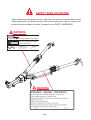
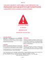
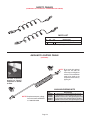
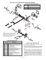
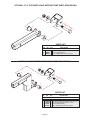
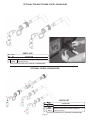
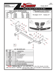
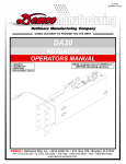
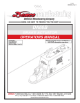
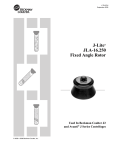
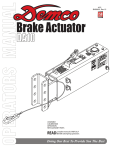
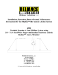
1-08
TB20017,Rev.12
Page 1
WARNING: Exceeding weight limitations or not using a towing vehicle larger and at least 500 lbs. heavier
than the tow bar and the towed vehicle combined can result in loss of towing vehicle control, separation
of the tow bar from the towing vehicle, or separation of the towed vehicle from the tow bar, causing severe
personal injury, death, and/or property damage.
TABLE OF CONTENTS
Warranty Registration .................................................................................................................. 3-4
Safety Sign Location ........................................................................................................................5
Safety Definitions ..............................................................................................................................6
Equipment Safety Guidlines & Lighting and Marking .......................................................................7
Safety Sign Care & Before Operation ...............................................................................................8
During & Following Operation ...........................................................................................................9
Highway and Transport Operations ............................................................................................ 9-10
Performing Mainenance..................................................................................................................10
Safety and Maintenance .................................................................................................................11
Important Notice .............................................................................................................................12
Bolt Torque......................................................................................................................................12
Hooking up, and Operating Instructions ................................................................................... 13-14
Unhooking Tow Bar................................................................................................................... 14-15
Aluminator® Tow Bar Parts Breakdown ................................................................................ 16-17
Lock Collar Assembly & Disassembly Instructions .........................................................................18
Safety Cable Kit Parts Breakdown..................................................................................................19
Auxiliary Lighting Cable Kit Parts Breakdown ................................................................................19
Optional Tow Bar Light Bar Parts Breakdown .................................................................................20
Optional Extended and Drop/Lift Hitch Attachments ......................................................................21
Optional Locking Pins .....................................................................................................................22
Warranty Statement ........................................................................................................................23
Page 2
Warranty Registration
4010 320th Street • Box 189 • Boyden, Iowa 51234
Toll Free 800-54DEMCO (800-543-3626) • FAX 800-845-6420
www.demco-products.com
❍
❍
❍
❍
❍
Ag
RV
Rental
Brakes
Marine
Very
Satisfied
Satisfied
Dissatisfied
Very
Dissatisfied
How satisfied are you with our product?
❍
❍
❍
❍
How satisfied are you with the dealership/distributor sales staff?
City
Dealer/Distributor Name
❍
❍
❍
❍
How satisfied are you with the company sales staff?
❍
❍
❍
❍
How satisfied are you with the delivery?
❍
❍
❍
❍
Did you have any contact with a Demco Representative?
If YES, how satisfied were you?
YES
❍
NO
❍
❍
❍
I would recommend this product to my family and friends.
YES
NO
Would you purchase again from DEMCO?
YES
NO
Since taking delivery, have you been contacted by the dealer?
YES
NO
Did you have any problems with this DEMCO product?
If YES, are you satisfied with the company’s resolution of your problem?
YES
❍
NO
❍
❍
❍
State
Why did you purchase this product?
Please list the specific source of information prompting this purchase.
After purchasing this product, do you see any needed product improvement?
If yes, what improvement?
What other products would you like to see DEMCO offer?
Comments
Owner’s Name:
City:
Mailing Address:
State:
Zip Code:
Model#:
Serial #:
Purchase Date:
Owner’s Signature:
Please return to DEMCO By FAX or tri-folding this form to the backside, it is pre-addressed.
Page 3
Postage
Demco
4010 320th Street, Box 189
Boyden, Iowa 51234
Page 4
SAFETY SIGN LOCATIONS
Types of safety sign and locations on the Aluminator™are shown in illustration below. Good
safety requires that you familiarize yourself with various safety signs, type of warning, and
particular function related to that area, that requires your SAFETY AWARENESS.
WARNING
Rating - 6500 lb. Capacity
2" Receiver hitch with proper weight rating required
WARNING
To Prevent Serious Injury Or Death:
Do Not Exceed Capacity of Towing Hitch,
Towbar, or Towing Vehicle
DETHMERS MFG. COMPANY
REV 2
4010 320th St., P.O. BOX 189
BOYDEN, IA. 51234
TOLL FREE: 1-800-54DEMCO (1-800-543-3626)
www.demco-products.com
Patent numbers: RE35,482
5,887,497 - 5,957,477
Patent pending
TB21008
WARNING
Page 5
SAFETY
TAKE NOTE! THIS SAFETY ALERT SYMBOL FOUND THROUGHOUT THIS
MANUAL IS USED TO CALL YOUR ATTENTION TO INSTRUCTIONS INVOLVING
YOUR PERSONAL SAFETY AND SAFETY OF OTHERS. FAILURE TO FOLLOW
THESE INSTRUCTIONS CAN RESULT IN INJURY OR DEATH.
THIS SYMBOL MEANS
ATTENTION
BECOME ALERT
YOUR SAFETY IS INVOLVED!
SIGNAL WORDS
Note use of following signal words DANGER,
WARNING, and CAUTION with safety messages.
Appropriate signal word for each has been selected
using following guidelines:
DANGER:
Indicates an imminently hazardous situation that,
if not avoided, will result in serious injury or death.
This signal word is to be limited to the most extreme
situations typically for tow bar components which,
for functional purposes, cannot be guarded.
WARNING:
Indicates a potentially hazardous situation that, if
not avoided, could result in serious injury or death,
and includes hazards that are exposed when
guards are removed. It may also be used to alert
against unsafe practices.
CAUTION:
Indicates a potentially hazardous situation that,
if not avoided, may result in minor or moderate
injury. It may also be used to alert against unsafe
practices.
If you have questions not answered in this manual, or require additional copies, please contact your
dealer or Dethmers Mfg. Co., P.O. Box 189, 4010 320th Street, Boyden, IA 51234
ph: (712) 725-2311 or (712) 725-2302 Toll Free: 1-800-543-3626 Fax: (712) 725-2380
http://www.demco-products.com
Page 6
SAFETY...YOU CAN LIVE WITH IT
EQUIPMENT SAFETY GUIDELINES
Every year many accidents occur which could have been avoided by a few seconds of thought
and a more careful approach to handling equipment. You, the operator, can avoid many
accidents by observing and following precautions in this section. To avoid personal injury,
study following precautions and insist those working with you, or you yourself, follow them.
Replace any caution, warning, danger or instruction safety decal that is not readable or is
missing. Location of such decals is indicated in this booklet.
Do not attempt to operate this tow bar under the influence of alcohol or drugs.
Review safety instructions with all users.
Operator should be a responsible adult. DO NOT ALLOW PERSONS TO OPERATE
OR ASSEMBLE THIS TOW BAR UNTIL THEY HAVE DEVELOPED A THOROUGH
UNDERSTANDING OF SAFETY PRECAUTIONS AND HOW IT WORKS.
Do not paint over, remove, or deface any safety signs or warning decals on your tow bar.
Observe all safety signs and practice instructions on them.
Never exceed limits of a tow bar. If its ability to do a job safely is in question
DON’T TRY IT.
LIGHTING AND MARKING
It is the responsibility of owner to know lighting and marking requirements of local highway
authorities and to install and maintain equipment to provide compliance with regulations.
Light bar kits are available from your dealer or from manufacturer.
Page 7
SAFETY SIGN CARE
• Keep safety signs clean and legible at all times.
• Replace safety signs that are missing or have become illegible.
• Replacement parts that displayed a safety sign should also display current sign.
• Safety signs are available from your distributor, dealer parts department, or factory.
How to install safety signs:
• Be sure installation surface is clean and dry.
• Decide on exact position before you remove backing paper.
• Remove smallest portion of split backing paper.
• Align decal over specified area and carefully press small portion with exposed sticky
backing in place.
• Slowly peel back remaining paper and carefully smooth remaining portion of decal into
place.
• Small air pockets can be pierced with a pin and smoothed out using piece of decal
backing paper.
REMEMBER
Your best assurance against accidents is a careful and responsible operator. If there is any
portion of this manual or function you do not understand, contact your local authorized dealer
or manufacturer.
BEFORE OPERATION:
• Carefully study and understand this manual.
• Give tow bar a visual inspection for any loose bolts, worn parts, or cracked welds, and make
necessary repairs. Follow maintenance safety instructions included in this manual.
• Be sure there are no tools lying on tow bar, towing unit or towed vehicle.
• Do not use tow bar until you are sure that area is clear, especially around children and
animals.
• Don’t hurry learning process or take tow bar for granted. Ease into it and become familiar
with your new tow unit.
• Practice operation of your tow unit and its attachments. Completely familiarize yourself
and other operators with its operation before using.
• Securely attach to towing unit. Use an appropriately sized and rated hitch ball and/or
a class III, class IV receiver and attach safety cables.
• Criss cross safety cables under tow bar, secure to mounting loops on towing vehicle.
• Do not allow anyone to stand between vehicles when backing up.
• Make sure tow rating on towing unit is high enough for what it is towing.
• To prevent swaying of towed vehicle insure all tires are inflated to specifications. Failure to
inflate tires evenly will result in towed vehicle to pull unevenly.
Page 8
DURING OPERATION
• Always follow state and local regulations regarding auxiliary lighting when towing. Be
sure to check with local law enforcement agencies for your own particular regulations.
Only safety cables (not elastic or nylon/plastic tow straps) should be used to retain
connection between towing unit and towed vehicle in event of separation.
• Do not load towed vehicle with cargo. Towed vehicles exceeding weight limits will
overload tow bar and may cause serious injury and damage.
• Beware of bystanders, PARTICULARLY CHILDREN! Always look around to make sure
it is safe to start engine of towing unit and moving towed vehicle. This is particularly important
with higher noise levels, as you may not hear people shouting.
• NO PASSENGERS ALLOWED- Do not carry passengers anywhere on or in towed vehicle.
• When halting operation, even periodically, set towing unit’s parking brake, shut off engine,
and remove ignition key.
• Be extra careful on inclines.
• MANEUVER TOWING UNIT AT SAFE SPEEDS.
• Avoid overhead wires or other obstacles. Contact with overhead lines could cause serious
injury or death.
• Avoid loose gravel, rocks, and holes; they can be dangerous for unit operation or movement.
• Allow for unit length when making turns.
• Do not work under raised components or attachments unless securely positioned and
blocked.
• Keep all bystanders and pets clear of work area.
• Operate towing unit from operators seat only.
• As a precaution, recheck hardware on tow bar every 200 miles, and correct all
problems. Follow maintenance safety procedures.
FOLLOWING OPERATION
• Following operation, or when unhooking, stop towing vehicle, set parking brake, shut off
engine and remove ignition key.
• Store tow bar in area away from human activity.
• Do not permit children to play on or around stored tow bar.
• Make sure parked vehicle is on hard, level surface.
• Wheel chocks may be needed to prevent vehicle from rolling.
HIGHWAY AND TRANSPORT OPERATIONS
• Adopt safe driving practices:
- Always drive at safe speed relative to local conditions and ensure that your speed is low
enough for an emergency stop.
Page 9
- Reduce speed prior to turns to avoid risk of overturning.
- Always keep towing unit in gear to provide engine braking when going downhill.
Do not coast.
- Do not drink and drive!
• Comply with state and local laws governing highway safety.
• Local laws should be checked for all highway lighting and marking requirements.
• Plan your route to avoid heavy traffic.
• Be a safe and courteous driver. Always yield to oncoming traffic in all situations, including narrow
bridges, intersections, etc.
• Watch for obstructions overhead and to both sides while towing vehicle.
• Operate with maximum visibility at all times. Make allowances for increased length and weight
when making turns and stopping.
PERFORMING MAINTENANCE
•
Good maintenance is your responsibility. Poor maintenance is an invitation to trouble.
•
Make sure there is plenty of ventilation. Never operate engine of towing unit in a closed
building. Exhaust fumes may cause asphyxiation.
•
Before working on tow bar, stop towing vehicle, set parking brake, turn off engine and
remove ignition key.
•
Always use proper tools or equipment for job at hand.
•
Use extreme caution when making adjustments.
•
Follow torque chart in this manual when tightening bolts and nuts.
•
After servicing, be sure all tools, parts and service equipment are removed.
•
Do not allow grease or oil to build up.
•
When replacing bolts, refer to owners manual.
•
Refer to bolt torque chart for head identification marking.
•
Where replacement parts are necessary for periodic maintenance and servicing, genuine
factory replacement parts must be used to restore your tow unit to original specifications.
Manufacturer will not claim responsibility for use of unapproved parts and/or accessories
or other damages as a result of their use.
•
If tow unit has been altered in any way from original design, manufacturer does not accept
any liability for injury or warranty.
•
A fire extinguisher and first aid kit should be kept readily accessible while performing
maintenance on this tow bar.
Page 10
WARNING: FAILURE TO FOLLOW THESE INSTRUCTIONS CAN RESULT IN LOSS OF TOWING VEHICLE CONTROL, SEPARATION OF THE TOW BAR FROM THE TOWING VEHICLE, SEPARATION OF THE TOWED VEHICLE FROM THE TOW
BAR, CAUSING SEVERE PERSONAL INJURY, DEATH, OR PROPERTY DAMAGE.
WARNING: ADDITIONAL SAFETY ITEMS
MAINTENANCE
Safety is of utmost importance at all times. To prevent personal injury or property damage, observe the following. Periodically check all bolts and nuts to ensure proper
tension or torque.
• Before allowing anyone to hook up or operate the
Aluminator , be sure they have read and understand the Check all pivot points for wear or breakage.
proper operating procedure.
TM
• This unit must be used with a Class III, 5,000 lb. Hitch Replace any worn or damaged parts with O.E.M. parts
only.
or higher.
• Be sure the steering components of the towed vehicle An occasional spray of lubricant may be required inside
are properly aligned.
the Lock Collar of the extending legs.
• The male receiver tube must fit snugly in the hitch receiver
and the safety pin must be in position to lock the receiver DO NOT lubricate any of the pivot points of the Aluminaand tube together.
tor These are self-lubricating washers and your towbar
could lose its self-supporting ability.
• NOTE: This unit can be backed up in moderate increments.
Any severe backwards cornering could result in damage to
Keep the Aluminator covered when stored on or off the
the Aluminator and/or towed vehicle chassis.
towing vehicle.
• For automatic transmissions: Consult your vehicle
owners manual for towing suitability with the drive shaft If the Lock Collars become limited in their movement they
connected. Otherwise, the towed vehicle will have to be may require disassembly using the instructions provided
equipped with a transmission pump or drive shaft discon- on page 18.
nect.
TM
TM
TM
• Be sure the SAFETY CABLES w/retainers are hooked Make sure all bolts are properly tightened and those
to both the towing and towed vehicles using the criss-cross requiring a set torque are up to specifications:
method.
Center Horizontal Pivot Bolt - 40 ft./lbs.
Front Vertical Pivot Bolt - 75 ft./lbs.
• Do not load the towed vehicle with anything as you may
(This bolt can be tightened to a torque range of 60 ft./lbs
exceed the towing capacity of the tow bar.
- 100 ft./lbs for the ease of maneuverability)
Rear Horizontal Pivot Bolt - 60-75 ft./lbs.
(See diagram on Page 13)
• Check to make sure that all lights are in proper working
order.
• Make sure the optional light bar is fastened securely at
the rear of the towed vehicle.
Products.
Thank you for Purchasing
Must have cable
anchors or a place
to connect cable to
frame
TOW BAR
Tow Bar positioning
should be parallel to
road surface or within 3”
in either direction
Page 11
Important Notice!
Be sure towed vehicle is suitable or adaptable for towing.
A few models are not towable!
Be sure to check if towed vehicle requires additional equipment such as a
transmission lube pump, free-wheel hubs, driveline disconnect or axle locks. Failure to properly
equip towed vehicle will result in severe damage to towed vehicle’s
transmission.
Be sure that towed vehicle’s steering wheel is unlocked and free to turn. Check manufacturer’s
specifications for the proper way to unlock steering wheel.
Be sure to check that receiver on towing vehicle is not inset to far. When attaching a Demco towing
product it is important that turning clearance is adequate. A receiver that is inset to far on a towing
vehicle will shorten turning radius. Failure to check this may result in towing or towed vehicle to be
damaged. It may be necessary to install a receiver extension to allow for proper turning clearance.
BOLT TORQUE TORQUE DATA FOR STANDARD
NUTS, BOLTS, AND CAPSCREWS.
Torque Specifications
Tighten all bolts to torques specified in chart unless otherwise
noted. Check tightness of bolts periodically, using bolt chart
as guide. Replace hardware with same grade bolt.
NOTE: Unless otherwise specified, high-strength Grade 5 hex
bolts are used throughout assembly of equipment.
Torque figures indicated are valid for nongreased or non-oiled threads and heads unless
otherwise specified. Therefore, do not grease or
oil bolts or capscrews unless otherwise specified in this manual. When using locking
elements, increase torque values
by 5%.
Bolt Torque for Metric bolts *
“A”
6
7
8
10
12
14
16
18
20
22
24
CLASS 8.8
lb-ft (N.m)
9
(13)
15
(21)
23
(31)
45
(61)
78 (106)
125 (169)
194 (263)
268 (363)
378 (513)
516 (699)
654 (886)
CLASS 9.8 CLASS 10.9
lb-ft (N.m) lb-ft (N.m)
10
(14)
13
(17)
18
(24)
21
(29)
25
(34)
31
(42)
50
(68)
61
(83)
88
(118)
106 (144)
140
(189)
170 (230)
216
(293)
263 (357)
--364 (493)
--515 (689)
--702 (952)
--890 (1206)
GRADE-2
GRADE-5
* GRADE or CLASS value for bolts and capscrews are identified by their head markings.
Bolt Torque for Standard bolts *
GRADE-8
CLASS 8.8 CLASS 9.8 CLASS 10.9
8.8
9.8
10.9
Page 12
“A”
GRADE 2
lb-ft (N.m) lb-ft
1/4”
5/16”
3/8”
7/16”
1/2”
9/16”
5/8”
3/4”
7/8”
1”
6
10
20
30
45
70
95
165
170
225
(8)
(13)
(27)
(40)
(60)
(95)
(130)
(225)
(230)
(300)
9
18
30
50
75
115
150
290
420
630
GRADE 5 GRADE 8
(N.m) lb-ft (N.m)
(12)
(25)
(40)
(70)
(100)
(155)
(200)
(390)
(570)
(850)
12
25
45
80
115
165
225
400
650
970
(16)
(35)
(60)
(110)
(155)
(220)
(300)
(540)
(880)
-(1310)
SAFETY CABLE & LIGHT CABLE INSTALLATION
Step 1. Remove safety cables from box and coil a cable
around each leg of the tow bar, starting near the pivot point.
Install the light cable (optional) by placing the coil over the
wire support rod. Secure the cable with the cable anchor
located on left connecting leg lock pin mount. Remove 1/4”
bolt, place anchor over coil of cable and replace bolt. This will
prevent the cable from pulling off and becoming damaged.
HOOKING UP THE VEHICLE TO BE TOWED
Refer to load limits on inside of front cover.
Step 4. Position the vehicle to be towed approx. 24” behind
the towing vehicle. The vehicles do not have to be in straight
alignment to complete the hook-up. Engage towed vehicle
and towing vehicle parking brake.
Step 2. Insert the lock pin block and sping into the Aluminator reciever tube and line up block with hole in tube. Insert
the Aluminator into a Class III or IV hitch.
TM
TM
Step 5. Slide and twist the legs into position to attach them
to the baseplate on towed vehicle. Secure to baseplate using the two attaching pins and 1/4” quick-lock pin. Attach
safety cables (see below). Now connect the lighting cable
between the towing vehicle and the towed vehicle lighting system or optional light bar. The coiled section of the cable will be
stored on the support rod of the left connecting leg. Towing
vehicle must be larger and at least 500 lbs. heavier than
the towed vehicle and tow bar combined.
quick-lock pin must be
closed properly. Fold ring
of Quick-Lock Pin to the
side of the pin that allows
ring to snap against pin.
If you have folded its ring
the wrong way it will not
snap against pin.
Step 3. Insert locking pin with star washer through receiver
on the block side and thread in pin until passes through. Slide
pin bushing over pin and into hitch receiver. Tighten pin use
5/8” wrench and install lock on pin.
Page 13
UNHOOKING THE TOWED VEHICLE
Step 1. Begin unhooking your unit by first applying both vehicle
parking brakes and unhook your lighting and safety cables.
Failure to have parking brakes applied could allow towed
vehicle to roll forward. This could result in limited space
between towing vehicle and towed vehicle.
Step 6. Hook safety cables to chain anchor of baseplate.
Note: Make sure safety clip is in working order.
Red Stripe
Step 7. Leave the electrical cable storage pin (circled above)
out for the locking procedure in step 6. When step 6 is completed, position cable on storage rod leaving enough slack,
and insert pin.
Step 8. Once you are secured to the tow bar, release towed
vehicle parking brake, and slowly back up the towed vehicle
straight back until one leg latches. Determine which leg
latched by having an assistant tell you. If you are by yourself
put towed vehicle in neutral or park, and apply parking brake.
Get out and check to see which leg latched. You can tell this
by which leg no longer has red stripe showing. To latch the
second leg, turn the top of towed vehicle’s steering wheel
into the direction of the leg that first latched, and slowly back
up again. This will latch the second leg. Once both legs are
latched, straighten wheels on towed vehicle, shut vehicle
off. If manual transmission, shift to neutral, unlock steering
wheel and make sure parking brake is released. Note: For
four wheel drive units, shift transfer case into neutral
also. Reminder: Consult vehicle’s manufacturer for towing
suitability of manual or automatic transmission vehicles.
Step 2. Use the Lock Collar Release lever to relieve any
pressure in the connecting legs between the two vehicles by
lifting up on handle.
Step 3. Remove pins that attach tow bar to towed vehicle.
Aluminator will remain in position. Slide the extendable legs
back into tube. Position electrical cable on storage rod and
insert pin to prevent cable from sliding off.
TM
Page 14
Step 4.
ward.
Now fold both legs together and push them up-
Step 5. Rotate them counter-clockwise into the storage position. The unit is self supportive in this position. Insert the
small hairpin into the lockpin inside the front yoke. Cover your
Aluminator and you are ready to drive your vehicle.
TM
NOTE: Picture shown in 90 degree position. Aluminator
will also store in 45 degree position.
TM
NOTE: If you need to store your Aluminator on the opposite side you must rotate the rear yoke 180° and rotate
the legs clockwise into the storage position.
TM
Page 15
PARTS BREAKDOWN
Order No. 9511007
REF.
NO.
1.
2.
3.
4.
5.
6.
7.
8.
9.
10.
11.
12.
13.
14.
16.
17.
18.
19.
20.
21.
22.
23.
24.
25.
26.
27.
28.
29.
30.
31.
32.
33.
34.
35.
36.
37.
38.
39.
40.
41.
42.
43.
44.
45.
PART
NO.
03796-81
03808
07161-95
02961
09386-89
09390-89
09404
00116
03806
03797-95
07218
03810
12961
04795
12535
09333
03807
12544-89
12545-89
07221
00684
02772
07222
00182
07223
11210-89
12458
07224
03872
10112-93
03873
12543-89
03809
03803-81
07164-95
02178
09384
03878-95
02397
12530-95
02243
5846
12431
07225
QTY.
1
2
2
2
1
1
1
1
2
1
1
1
2
2
2
1
4
1
1
1
1
1
1
2
1
1
4
2
2
2
2
2
4
2
2
2
4
2
2
1
1
1
1
REF.
NO.
DESCRIPTION
Male Receiver with bushings
Crosstube Bushing Only
3/4”-10NC x 4-1/2” Hex Head Bolt (Gr.5)
3/4”-10NC Nylon Insert Locknut
Front Yoke
Rear Yoke
3/4”-16NF x 2-1/2” Hex Hd. Bolt (Gr.5)
5/32” x 1-1/2” lg. Cotter Pin
Yoke Washer
Thrust Plate
3/4”-16NF Hex Jam Nut
Connecting Arm Bushing
1-3/4” Round Vented Caplug
1/2”-13NC x 1” Hex Head Bolt(Gr.5)
Stop Washer
Neoprene O-Ring (1/8” x 1-1/4” OD)
Ear Washer
Left Front Connecting Leg
Right Front Connecting Leg
Light Cable Anchor
1/4”-20NC x 1-1/2” Hex Head Bolt (Gr.5)
1/4”-20NC Nyon Insert Locknut
Lanyard Cable
1/8” Small Hair Pin
5/32” x 3/4” Roll Pin
Wire Support
Lock Pawl
Leg Seal
Coil Spring
Lock Collar
Snap Ring
Rear Connecting Leg
Connecting Clevis Washer
Connecting Clevis
1/2”-13NC x 3” Hex Head Bolt (Gr.5)
1/2”-13NC Nylon Insert Locknut
3/4” 21 Ga. NR Machine Washer SS
Attaching Pin
1/4” Quick Pin
Lock Collar Release Tool w/Grip
Black Handle Grip Only
Lock Pin F/ Reciever
Rplacement Key
Split Ring
Please order replacement parts by PART NO.
4
and DESCRIPTION.
38
PART
NO.
46. 09343
47. 10117
48. 11770
49. 11825
50. 11874
- 9523042
10173
11
43
9
31
49
30
29
47
28
28
20
18
41
16
42
18
14
12
3
8
13
7
38
18
17
6
5
48
13
4
3
Page 16
14
16
38
38
1
43
Plastic Bearing (Nyliner)
O-ring 1.862 I.D. x .103 Cross Section
Washer, .782 ID, Stainless Steel
Protective Bellows Boot
Cable Tie
Vinyl Storage Cover (Optional-not shown)
Copper Anti-seize .25 oz
50
2
43
6
2
1
2
4
1
32
10
2
DESCRIPTION
Please order replacement parts by PART NO. and DESCRIPTION.
9
44
QTY.
18
39
CROSS SECTIONAL VIEW OF ASSEMBLED FLEX- JOINT
36
34
Yoke Washers
35
Pivot Bushing
Ear Washers
Inner Sleeve
Crosstube
Bushing
34
Right
Connecting Arm
75 ft/lbs.
33
37
60 ft/lbs.
40
40 ft/lbs.
Left
Connecting Arm
O-Ring
36
35
40
34
33
37
49
25
PAT. PEND.
22
46
28
46
47
29
34
32
31
30
50
21
19
26
28
27
DECALS
ORDER
NO.
23
24
TB21009
11959
TB21004
TB21008
QTY.
2
2
1
1
1
DESCRIPTION
Aluminator Decal
Safety Latch Stripe (Red)
User Instruction Decal
Warning Do Not Exceed Weight Limits &
Manufacturers Patent / Hitch Rating Decal
Please order replacement parts by PART NO. and DESCRIPTION.
45
25
Page 17
39
LOCK COLLAR MAINTENANCE INSTRUCTIONS
4
3
13
5
12
6
11
14
7
10
5
8
2
9
11
15
15
1
DISASSEMBLY:
REASSEMBLY:
1.
1. Leave Aluminator®on towing vehicle or clamp hitch tube
in heavy-duty vise.
2. With a screw driver, pry up on bottom of release handle
(#13) ear to to remove handle. Remove bellows boot
2.
(#14) from lock collar (#6) and slide bellow boot back.
Pull back the Lock Collar (#6) and push the Rear Leg (#7)
approximately halfway in. This will hold the Lock Collar
in the release position.
3. Remove the snap-ring (#8).
3.
4. While holding Lock Collar, pull rear connecting leg outward
4.
to the latch position and collar will then slide off outer tube
and hang on rear leg. Inside of lock collar (#6) can be
cleaned at this time. Lock pawls (#11) can be removed
at this time for cleaning by pushing rear leg (#7) back
5.
into outer tube about 1”, this will push lock pawls out for
removal. If not removing shaft go to step 7. For shaft
removal or o-ring replacement; Remove caplugs (#1)
6.
from the Front Connecting Leg Tube (#2) and unbolt
Connecting Clevis (#3) from Rear Connecting Leg (#7)
7.
by removing the 1/2” x 3” bolts (#4), washers (#5) and
locknuts (#12).
8.
5. Remove Lock Collar (#6), Lock Spring (#9), and O-ring
(#10).
6. Slide out Rear Leg, be careful not to damage the shaft
9.
seal.
10.
7. Clean o-ring groove area and oval hole in outer tube and
lock pawls. Inspect all parts for excessive wear.
8. Reassemble this leg, If shaft not removed, go to step 3
of reassembly. Repeat steps for other side.
Page 18
Reinstall o-ring (#10) on outer tube. Lubricate only the
o-ring with a lite coat of copper anti-seize (included with
Aluminator® Part number 10173). (Note location in Figure
A)
Slide rear leg into front connecting leg tube, being carefull
not to damage shaft seal (see Figure A). A slight twisting
motion will aid in the installation. Slide the rear leg in untill
the shaft groove matchess up with the square pawl holes.
Replace the two lock pawls (#11) into the tube insert.
Replace Lock Spring (#9) and Lock Collar (#6).
NOTE: The smaller end of the tapered lock spring (#9) must
be against the Lock Insert part of the Front Connecting
Leg.
Pull Lock Collar back and slide the rear leg in approximately
halfway. This will hold the Lock Collar in the release position.
Replace the snap-ring (#8).
Replace rubber bellows boot (#14) to lock collar (#6) with
nylon ties (#15).
Reattach Connecting Clevis (#3) on Rear Connecting Leg
(#7) with the 1/2” x 3” bolts (#4), washers(#5) and locknuts.
Tighten bolts until clevises are just snug.
Reinstall the caplug (#1).
Reattach release handle (#13) by tapping on with a rubber
mallet.
SAFETY CABLES
(STANDARD FOR AluminatorTM & REQUIRED FOR TOWING)
1
PARTS LIST
REF. PART
NO.
NO. QTY.
1
9523003
1. 07230
2
DESCRIPTION
Safety Cable Kit (complete)
Coiled Safety Cable w/Hooks
Please order replacement parts by PART NO. and DESCRIPTION.
AUXILIARY LIGHTING CABLE
(OPTIONAL)
NOTE: To be used with optional
Light Bar, the ends will
have to be cut off light bar
harness.This end will then
need to be wired to the
receptacle of the auxiliary
lighting kit.
Possible mounting
location for lighting
receptacle in vehicle
air dam.
AVAILABLE WIRING KITS
ORDER
NO.
NOTE:For replacement parts, call original manufacturer or DEMCO
at 1-800-543-3626
9523004
9523006
9523009
9523010
9523011
DESCRIPTION
4-WayAuxiliary Coiled Lighting Cable w/recpt.
6-WayAuxiliary Coiled Lighting Cable w/recpt.
9523004 & Towed Vehicle Tail Light Wiring/Diode Kit
Towed Vehicle Tail Light Wiring/Diode Kit Only
9523006 & Towed Vehicle Tail Light Wiring/Diode Kit
Please order replacement parts by PART NO. and DESCRIPTION.
Page 19
OPTIONAL LIGHT BAR (KKLB) PARTS BREAKDOWN
COLOR CODE FOR WIRING HARNESS
WHITE
Ground
BROWN Tail Lights, License Plate Lights,
Light Cluster Bar & Clearance Lights
YELLOW Left Turn and Stop
GREEN Right Turn and Stop
7
6
1
8
9
8
14
8
1
2
9
9
4
8
3
5
15
8
9
16
4
12
13
13
1
10
8
11
1
11
NOTE: The wires to the optional light
bar should be run along the car and
fastened so as not to damage the
finish of the towed vehicle.
LIGHT BAR PARTS LIST
REF. PART
NO.
NO. QTY.
1.
2.
3.
4.
5.
6.
7.
8.
9.
10.
11.
12.
13.
14.
15.
16.
01772
01857
01773
01886
02385
02386
01856
02772
00092
01777
01778
02198
00068
01911
01912
01890
DESCRIPTION
AluminatorTM Light Bar (complete)
KKLB
2
1
1
4
1
2
1
10
6
2
4
1
4
-
Nylon Security Strap with hooks & tightener
Left Tail/ Brake and Signal Light w/Lenses
Brown Jumper Wire
Wire Holder (metal)
Light Bar Framework
Adjustable Light Bracket
Right Tail/ Brake and Signal Light w/Lenses
1/4”-20UNC Nylon Insert Locknut
1/4”-20UNC x 1/2” Hex Head Bolt
Light Bar “Z” Bracket
3” Suction Cup w/Bolt (#13)
Light Bar Wiring Harness (new style)
1/4”-20UNC x 3/4” Hex Head Bolt
Large Red Lens
Small Red Lens
Clear Lens
Please order replacement parts by PART NO. and DESCRIPTION.
TESTING LIGHTS BEFORE USE
1. With headlights in “ON” position, the tail lights and the
clearance lights should be lighted.
2. Start engine and have someone depress brake pedal.
Brake lights of the light bar and towing vehicle should
come “on” and “off” simultaneously with each application.
3. Turn left turn signal on. Left turn light of light bar and towing vehicle should flash simultaneously. Should the turn
signal lights of the light bar function opposite to those of
the towing vehicle, it is probable that the YELLOW and
GREEN wires have been reversed. Check the plug connections to make sure wire colors are not crossed at any
point. If plug connection is incorrect, correct problem by
reversing yellow and green wire connection on the towing
vehicle.
Page 20
OPTIONAL 3-1/2” EXTENDED MALE RECEIVER TUBE PARTS BREAKDOWN
3
To
rqu
eT
o1
20
ft/l
bs
.
2
1
2
PARTS LIST
REF. PART
NO.
NO. QTY.
9523008
1. 07498-81 1
2. 03808 2
3. 02961 1
DESCRIPTION
3-1/2” Extended Male Receiver (complete)
Extended Receiver Tube 3-1/2” with bushings
Cross Tube Bushing
3/4”-10UNC Nylon Insert Locknut
Please order replacement parts by PART NO. and DESCRIPTION.
OPTIONAL DROP/LIFT RECEIVER HITCH PARTS BREAKDOWN
3
2
1
To
rqu
eT
o1
20
ft/l
bs
.
2
PARTS LIST
REF. PART
NO.
NO. QTY.
1.
2.
3.
9523038
9523039
11500-81
11501-81
03808
02961
1
1
2
1
DESCRIPTION
6” Drop/Lift Receiver Hitch (complete)
3” Drop/Lift Receiver Hitch (complete)
6” Drop/Lift Receiver Tube (shown)with bushings
3” Drop/Lift Receiver Tube with bushings
Cross Tube Bushing
3/4”-10 UNC Nylon Insert Locknut
Please order replacement parts by PART NO. and DESCRIPTION.
Page 21
OPTIONAL TOW-BAR TO BASE PLATE LOCKING PINS
1
2
PARTS LIST
REF. PART
NO.
NO.
9523043
1.
5847
2. 12431
DESCRIPTION
Tow-Bar to Base Plate Locking Pin Set
Tow-Bar to Base Plate SingleLocking Pin Assembly
Replacement Keys
Please order replacement parts by PART NO. and DESCRIPTION.
OPTIONAL 3-PIECE LOCKING PINS
2
3
1
PARTS LIST
REF. PART
P
NO.
NO.
3
9523044
9
95
1.
5847
2.
5846
3. 12431
DESCRIPTION
3-Piece Locking Pin Set
Tow-Bar to Base Plate SingleLocking Pin Assembly
Tow-Bar to Motor Home receiver Locking Pin
Replacement Keys
Please orde
order replacement parts by PART NO. and DESCRIPTION.
Page 22
DEMCO PRODUCTS - AluminatorTM Tow Bar
ORIGINAL PURCHASERS LIMITED WARRANTY
1. Extent and Duration of this Warranty:
Your Demco AluminatorTM has a Lifetime Limited
warranty to be free from defects in materials and
workmanship under normal use and service from date
of purchase by the original (first) retail owner, or until it is
resold or transferred by the original owner. Any part of
the Demco AluminatorTM found in the judgement of the
manufacturer to be defective in materials or workmanship
will be repaired or replaced at the manufacturer’s option
without charge for parts or labor to the original owner.
In addition, the warranty does not extend to repairs made
necessary by normal use of parts, accessories or other
equipment which in the judgment of Warrantor, are either
incompatible with the Demco Tow Bar, or affect its operation, performance or durability.
This warranty does not cover:
1) normal wear and tear
2) road film or gravel damage to paint
3) paint
4) rust damage
5) Any Demco Tow Bar that has been loaded in excess
of the load capacity stated on the tow bar identification
label.
2. Manufacturer and Warrantor of Tow Bar:
Dethmers Manufacturing Co.
4010 320th Street
P.O. Box 189
Boyden, IA 51234
(712) 725-2311
Warrantor has a policy of continuous product improvement.
We reserve the right to change or improve the design of
any Demco Tow Bar model, including but not limited to
state of the art changes, without assuming any obligation
to modify any tow bar previously manufactured.
3. Repair or Replacement Procedure:
If your Demco Tow Bar develops a defect during the warranty period, promptly notify Dethmers Manufacturing
Co. customer service department. Until such notice is
received, Warrantor will not be responsible for any repair
or replacement.
Warrantor assumes no responsibility to the owner for loss
of use of the tow bar, loss of time, inconvenience or other
damage consequential or otherwise, including, but not
limited to expense for gasoline, expense of transporting
the tow bar to the dealer and expense of returning the
tow bar, mechanic’s travel time, telephone or telegram
charges, road service/towing charges, rental of another tow
bar during the time warranty repairs are being performed,
travel, lodging, loss or damage to personal property or
loss of revenue or earnings.
Upon receipt of notice from you, Warrantor will have a
choice of options in replacing any part it determines to
be defective:
a) Warrantor may require you at your own expense
to deliver or ship the part to its factory or authorized dealer. Any defective part will be repaired
or
replaced and returned to you free of charge.
Any part returned to Warrantor and found not to be
defective will be returned to you freight collect with
an explanation.
b) Warrantor may elect to ship a new part to its dealer
to be exchanged free of charge for the defective
part returned by you to the dealer.
c) Warrantor may elect to ship or deliver a replacement
part to your address.
4. Limitations on Warranty Coverage:
Coverage under this warranty will be valid only if the customer warranty card is returned by the original
purchaser within 30 days of purchase.
Coverage under this warranty will be effective only when a
copy of the original invoice, showing the date and location
of purchase, accompanies any claim for warranty.
Warrantor has no liability whatsoever and this warranty is
null and void if any Demco Tow Bar has been misassembled
or subjected to neglect, negligence, misuse, accident or
operated in any way contrary to the operating and maintenance instructions as specified in the Demco Owner’s
Manual for that model tow bar.
This warranty does not cover any tow bar that has been
altered or modified so as to affect the tow bar’s operation,
performance or durability, or that has been modified to
change the intended use of the tow bar.
5. Limitations of Implied Warranties:
All implied warranties, if any, expire and terminate upon
expiration of this warranty. Some states do not allow
limitation on how long an implied warranty lasts, so this
limitation may not apply to you.
6. Limitation of Consequential Damages:
Warrantor’s responsibility under this warranty extends
solely to repair or replacement of your Demco Tow Bar
and its component parts.
Warrantor does not assume responsibility for, nor shall
it be liable for, any special, incidental or consequential
damages. Some states do not allow the exclusion or
limitation on incidental or consequential damages, so the
above exclusion or limitation may not apply to you.
7. Use of Serial Number Identification (SN):
The SN is a 6 digit number located on the tow bar identification label. The label is located on the bottom side of
the tow bar rear yoke. Be sure to include the SN number in all communications with Warrantor or its dealers
concerning the warranty.
Serial No.________________________
8. Purchaser’s Rights:
This warranty gives you specific legal rights, and you may
also have other rights which vary from state to state.
9. Exclusive Warranty:
This is the only express warranty made by Dethmers
Manufacturing Co. on your Demco Tow Bar and no agent,
employee, or other person is allowed to change or add to
this warranty.
Page 23
P.O. BOX 189
4010 320th St., BOYDEN, IA. 51234
PH: (712) 725-2311
FAX: (712) 725-2380
TOLL FREE: 1-800-54DEMCO (1-800-543-3626)
www.demco-products.com
Page 24