1
4%
.56%
434
%
!"
#$
%&! ''(#()%$*+&! '' ,
%-./012221030444130
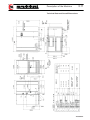
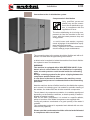
Forward
Versions
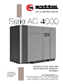
- AC 4000
- AC 4000 Plus
Voltages/Frequencies
- V 230/50 - 400/50 Hz
- V 230/60 - 460/60 Hz
The present manual, written in english, is the official
translation of the manual in Italian, chosen as reference
language by Ing. ENEA MATTEI SpA.
The paper copy will be available for over 10 years after end
of production of the machine to which it refers.
The content of this document cannot be used, reproduced or
disclosed to third parties without the explicit written consent of
Ing. ENEA MATTEI S.p.A.
Ing. ENEA MATTEI S.p.A. reserves the right to modify the
characteristics of the machine subject of this document without
prior notice.
Copyright 2010 by Ing. ENEA MATTEI S.p.A.
This Instruction Manual meets all the requirements of Directive
2006/42/EC.
It is to be considered valid for both the machines with the CE
Marking and those without it.
Important Note
This manual should always be used together with the
“MAESTROXS User’s Manual”, code TECA2G-007
TI010G0021
7%+
General Information
809%450%
4.30
:;%.34.4
.3.5.35355%3.
50%<
=7>
7%%?84*%437%.8@64
64540A4+4
43452:4?443452
4450.3A444
General Information - SAFETY
644%4B47%.0
449%4
43.3604
6(1(
6(1
6(1
6(1,
6(1'
6(1!
6(1(
6 1(
6 1,
6 1'
Description of Machine
7%43.35
353%?%%044
Transportation and handling
Installation
4.3044
%33%33
352B
044.3044496
C3?8
Safety Devices
0043%
Use of compressor
*2
04
+43%%
%*%4
1(
61(
61((
6,1(
6,1
6,1
6,1,
6,1'
6,1)
6'1(
6'1
6)1(
6)1
6)1,
6)1'
6)1)
Maintenance
D6%53B404
53B.%%?%%6E%36543.%
%65%E
%65.%4%6E%365%?%?4
%365%.%
%365%E4%04
%356
934
9%456
5%33%0
630044640%6
44356%B
3504*0:4353%?3
*0:444
49%3603
<353%>54
61(
61
61
61,
61'
61)
61F
6F1(
6!1(
6(1(
6((1(
6( 1(
TI
7%.0
1.01
Symbols in the manual
540%404809%44535
A4%403%%8
0434.501
SYMBOL
MEANING NOTES
!F
59%9%26?45%44394506.5..4809%441
G
Danger
3462554B.33?.%.541
83.%+9%3B25544809%1
!
Warning
2464449%.50354%0.541
☞
Notice
4524535B8.344.%.01
Further information
544809%34+9%3B436.5.01
54.0543%4525543..325
3?%01
583%9344.3453045434.540%1
Damage risk
34565064B.3.+0%4626%9806
40562553331
Visual Check
3004538?4%353B1 544809%3%49.
5434.41 544:04?%353B40
2646431
Acoustic Check
30045384343353B1
544809%3%49.5434.41544:%4
%41
TI
7%.0
1.02
Purpose of Document
540%345353%3534345.03544%%
%45434.45??33?034.5035
0.398Ing. ENEA MATTEI 111
☞
NOTE : This manual should be considered an integral part of the machine, and should
stay with it during the entire life span of the equipment.
Keep this manual and all of the attached documents in a place easily accessible to all
staff in charge of the control or the maintenance of the machine.
Ing. ENEA MATTEI 111reserves the right to subject the supply of further copies to the
repayment of charges and the acceptance of special provisions with respect to the
legitimate defense of intellectual, patent, and executive identity and functional property
of the product and/or its parts.
It is understood that forwarding all or part of this manual to third parties is not tolerated
unless with the prior written consent of Ing. ENEA MATTEI 111for both the text, the
illustrations and the diagrams attached.
Ing. ENEA MATTEI 111reserves the right to make changes without prior notice. Any
change, supplement or suppression of elements, components, functions or cycles of the
machine, not previously agreed upon with Ing. ENEA MATTEI 111 releases the
manufacturer from any responsibility whatsoever.
540%4.5454?36.5035044%865025
5943353%83%.54840353%43.54?%664
5.042%%4544%4345.03448.0??
33?031
540%4.4..254B2%6.5344635:.0353%%33%
6044.9554356.54.503554?3641
540%46%.503534.050466%%4.
.4.
2B63466.3..33865%.4.50351
*334.50354440552B6?04:3
6%43364.85861
Applied directives and technical standards
50355494604330%3255
<4.85%544%
:04>43505European Directive 2006/42/EC1
5%49%26?45.34498Ing. ENEA MATTEI 111460B
0B5.%43.50351
List of Directives and Technical Harmonized Standards
MACHINERY DIRECTIVE 2006/42/EC
ELECTROMAGNETIC COMPATIBILITY (EMC) DIRECTIVE 2004/108/EC
LOW VOLTAGE DIRECTIVE 2006/95E
EN 1012-1 0444?3004H.8:0404441
TI
7%.0
1.03
Required Qualifications for Operators
Entry Level Machine Operator #;%.3($
;%.4..9%3840%4B41150352554.
3%454593883%40%.34.J4044
41
(
Second Level Machine Operator #;%.3 $
;%.4..9%3854B.:%.3(%45035
254334.834.043.3J40444.341
(
!!
5356.5503.503545%5?%%5.44%
:0443.335.41
545%92.54449%41
I%24543.5.44%.%433654356.5035
☞ Important
This qualification includes those responsibilities typically subdivided into two separate
qualifications. For the operator in charge of our machines, a specialization course is held to train
the operator to be able to perform all of the actions necessary to operate the machine even with
some of the protections disconnected. However, this requires a certain competence by the operator
and extreme care by the manager of the factory so that the said operator carries out only the
established operations.
((
Mechanical Service Engineer
:%.69%50350%3425
43334?0353%438%%J404
3803%%.5344841
54440238?4%33%4840425%?
?%61
(
Electrical Service Engineer
:%.69%50350%3425
433341CE454356.%%%33%J40403
1
CE4549%25%??%64394459+41
(,
(
The Manufacturer’s Engineer
:%.6.050.3.030%+4
43%44336525355496255
41
TI
7%.0
(1,
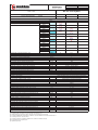
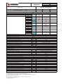
'(
Identification data of the Manufacturer and the Machine and the location of the nameplate “CE
MARKING”
Ing. ENEA MATTEI S.p.A. 4.45035A 40.33.08255%24
.3255.%%2634-
- Declaration of conformity - CE Marking – Instruction Manual
43.3%50356?45.%%26
%9%.05CE MARKING-
%
%09
K.0.3
%?8
44
2
09.4
8
B38
%@65
044.0.3
5 <
=7> % 54 9 % 5 94 .
5 0351
'
5 %? <DECLARATION OF CONFORMITY>
549351
4.90? 5< CE MARKING>%
E+356. 5%4 .0354.
5400%4%5405
1
5% 5< CE MARKING>%9 33%%8
060?.003553404
:.05081
TI01
0G0021
7%.0
1.05
General notes on delivery
Upon receipt of the machine please check that:
The supply complies with the order specification.
There are no damages due to transportation or other reasons.
(In the event of damage or missing parts, please inform immediately and in detail the forwarding agent or
Ing. ENEA MATTEI S.p.A.)
ALWAYS STATE THE MACHINE SERIAL NUMBER AS WELL AS THE PRINT NUMBER OF THIS
CATALOGUE WHEN MAKING ANY REQUEST TO Ing. ENEA MATTEI S.p.A. OR ONE OF THEIR
SERVICE CENTRES.
Final inspection
The manufacturer carries out the final inspection of the machine directly, during the production phases, in
compliance with the company quality system.
Ing. ENEA MATTEI S.p.A. is responsible for the machine under its original configuration.
Ing. ENEA MATTEI S.p.A. refuses any responsibility for improper use of the machine, for damages due
to operations which are not described in this manual or unreasonable jobs.
Safety precautions
The final user should comply with the instructions given by the seller, concerning:
• safety devices already installed on the machine
• instructions for correct machine installation
• correct use and periodic maintenance of all the machine components, including safety devices
• regulations of current laws
The following safety precautions define both the behaviour and obligations to be observed when carrying
out the activities listed in the manual, the instructions for the machine use and the way how to operate
under safety conditions, for the staff and the surrounding environment.
Machinary Directive
3583?045 )E, E
"
*C
(8 )1
Machine
Machine means the functional assembly composed of: control unit, processing unit, working and resting
equipment, systems (electrical, pneumatic, hydraulic, cooling, lubrication systems) and any group completing the system functionality.
Working area
Working area means the protected volume limited by guards to prevent injuries and aimed at operation
during the machine processing.
TI
7%.0
1.06
Authorized staff
Authorized staff means personnel duly trained and appointed to perform the activities listed below and
that make up the operating instructions for the machine.
Appointed staff
Appointed staff means the personnel who, although not participating materially in the work, supervise
the work of others, for example the responsible engineer.
Transport
Transport means all those operations regarding the handling of the machinery or part of it
Installation
Installation means the mechanical, electrical and fluid system integration of the machine into a production reality, in compliance with specified requirements.
Commissioning
Commissioning means the functional check of the machine installed.
Operation
Operation means the operating mode at which the machine produces compressed air according to all
settings and controls inserted by the control device.
Decommissioning
Decommissioning means to disconnect mechanically and electrically the machine from a production
line.
Dismantling
Dismantling means dismantling and eliminating the machine components.
Maintenance and repair
Maintenance and repair means the regular check and/or replacement of parts or components of the
machine and any action to identify the cause of failure, ending with the machine resetting to the design
operating conditions.
Improper use
Improper use means using the machine out of the limits specified in the technical documentation.
Applicability
The regulations should be applied when performing following activities:
• Transport, installation and setting up
• Manual operation
• Continuous operation
• Decommissioning and dismantling
• Maintenance and repair
that compose the use procedures foreseen for the machine.
TI
7%.0
1.07
Installation and commissioning
“The installation and commissioning are only permitted to authorised staff.
During installation, handle the machine components as indicated in this manual; if lifting is necessary,
verify first the correct fixing of specific devices for lifting and use adequate slings and equipment.
The machine installation should be as free as possible from any material preventing or limiting its view.
If there are any, remove fixing brackets or eyebolt blocking devices, previously fitted to allow the transport.
Check that all the machine safety devices are correctly fixed and there are no moving or loose parts.
Also check soundness of the control unit components.
Connect the machine pneumatic system to the air distribution system and carefully check that pressure
is set to the correct value.
Check consistency between the voltage set on power transformers and the voltage value of the electrical supply.
Before connecting the machine electrical system, check that the mains isolator is blocked in the open
position.
Verify that accident preventing guards are correctly installed and in perfect state.
According to the different national law regulations, the Customer might be required to inform
the Certified Authorities of the installation and set up and/or to undergo a system check if the
machines are provided with tank (SPV) or pressure devices (PED).
Periodic inspections are also foreseen.
☞
The machine safety is not guaranteed in case of removal, by-pass or tampering of the
safety devices on the machine.
To stop the machine during an emergency, press the emergency stop button.
Operating the machine
Only authorised and duly trained staff or at least with a sufficient technical experience should operate
the machine. The staff in charge of operating the system should be aware that the knowledge and
application of safety regulations is in an integral part of their job.
Unskilled personnel should not access the operating area and the machine control panel when the
system is live.
Before starting the machine, carry out following operations:
• Carefully read the technical documentation;
• Get information about the operation and position of emergency stop devices on the machine;
• Know which protections and safety devices are fitted on the machine, their position and operation.
It is forbidden to either disconnect or partially remove the protections and safety devices. The same
applies for danger signals located in particular areas of the machine. It is strictly forbidden to access the
working area and the control and power cabins during operation of the equipment (even partial) or
immediately after it is switched off.
Protections and safety devices should be kept in perfect state so as to allow right operation; in case of
failure they should be repaired or replaced.
The use of not authorised components and accessories for the protections and safety devices may lead
to malfunctioning and dangerous situations for the operating staff.
TI
7%.0
1.08
Decommissioning and dismantling
Only authorised staff is allowed to decommission and remove the machine.
Before setting the machine out of operation it is necessary to disconnect the mains isolator and block it
in the open position.
Discharge oils and fluids, remove all moving parts.
Disconnect the mains isolator cable, by cutting out the power wires and then the earth wire.
Disconnect the power supply cable from the machine main switch and remove it.
Disconnect the machine pneumatic equipment from the air distribution system.
Remove the machine from the working area following the instructions given in this manual. Before lifting
it, verify the correct use of lifting devices and use only suitable equipment.
Waste disposal should be performed in compliance with the laws in force in the country where the
machine is installed.
❑
❑
❑
❑
Installation, setting up and use of compressor should be carried out in compliance with the standards and the rules in force concerning safety at work.
The owner of the machine is responsible for its good maintenance, an essential condition to ensure
safe operation.
Those machine parts that due to improper use or wear do not ensure safe operation should be
quickly replaced.
Only trained, authorised and skilled staff should perform the installation, use, maintenance and
repairs.
In case of difference between the instructions given in this manual and those foreseen by current
laws concerning safety, it is recommended to apply the more restrictive ones.
Maintenance and repair
Only authorised personnel should carry out maintenance, troubleshooting and repairs.
Any maintenance and repair in progress should be signalled by a specific sign, stating the maintenance
condition and placed on the control panel until completion of the job, even if temporarily interrupted.
All operations for installation, maintenance or replacement of components on the machine or on the
control unit should be performed with switched off system.
Therefore, the main switch should be on OFF (OPEN) position and blocked with the safety lock to
prevent any movement to the ON position.
For compressors equipped with INVERTER, before performing any maintenance job, wait at least
5 minutes after you have disconnected the electricity supply.
Before acting, people in charge of maintenance should first check following conditions:
• that any receiver under pressure has been exhausted.
Before intervening on pneumatic or lubricating systems and specifically on pipes, receivers, hoses and
other components under pressure, the staff in charge of maintenance should reduce the internal pressure of the plant down to the ambient pressure value.
Faulty components must be replaced with others having the same code.
If during troubleshooting it is necessary to carry out jobs with the control unit and the machine live, all
precautions should be taken, as required by the safety standards to operate under dangerous voltages
and with moving parts.
At the end of the maintenance and troubleshooting jobs, all disconnected safety devices should be
reset.
Maintenance, repair and troubleshooting should be ended by the checking of the machine operation and
of all its safety devices.
TI
7%.0
(1!
!
+3534.449%.f 33% 604 5 .%%26040%%8
540A4+4-
0#3%69%6 2B 435 4 5 %86 . .43%L4
:31$1
4%%?%.%6M
.955%3.4%% 5 035 4%%4%.25%4 94?6
504445%8M
.+%84?34 5 :0 :04#4354 %33%
2B032B31$M
.%33%:030%33? )E!'E
M
:%65630%86254
) ,(M
84.8?349.. 5 68 4%8 %4 #4354..% 42354
6484044.8?%?431$4089 :985%24.3 38.
4%%M
6:030%86254
),FM
7%.0
(1(
*88..0545 03 5 4%% 31
111
4%284?%9%05354A4:441
C2?8:4903% 04 25 .34 54 0%%284 46 5
5035%1
*830032554?3 3 %284 3 5 8 . 03544% 09
58.0.325355%.8?803525?449%43.85
.539%05.339850354354-.%33%0353%
B04.2B:%825%439659%038.5<"#$
"#$
%&
$'
$*+
>35540%1
3%3%4?303%44853%%..31
3
7
!
!
503508?.0:5%30.54449J321
54453543549%31
430%48%284986%441
44%28432550+0033385.%%26(80%.035
%09
+30.5:4
,E.3#.?%9%$
'::8
40%.845%?8.444300.2498.%%6
38.5<"#$
"#$
9$
9$
$*+>35540%.26
!
53%44491
?
3
!
;
!=@
>=J=
9=
!!=@
;
;
7=
;
<=
8:4.?.5353%4?3540A48+%5353%
434.543045%944-
'
=
7
!
9
>
4 % , H ,,! "
N7 #I60$ %8
- &! 'E,(F), #03435$ *O- &! 'E,(F),!
0%- ./01961
11 q )! N6
!F
7%.0.8
G
!F
!
G
2.01
To operate the machine under any operating condition, including maintenance, it is not
necessary that more than one person be present.
Using more than one person is superfluous and, in any case, not allowed for safety
reasons.
The employer should instruct the staff on the risks of accidents, on safety devices and on the
general rules concerning prevention and protection, as established by the European Community Directives and by the current legislation in the country where the machine is installed.
The operator should be aware of the location and operation of all controls and of all the
machine features.
The operator should also have read the entire manual.
Only skilled engineers should carry out maintenance jobs, after having duly prepared the
machine.
Any unauthorized tampering or replacement of one or more parts of the machine, or
the adoption of accessories that modify the use of the machine and the use of different
materials than those recommended in this manual, may be a potential risk of accidents.
It is strictly forbidden for the machine to be operated by two persons contemporaneously, one inside the guards and one on the control panel.
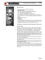
Dangers and residual risks
!F
!F
During the design phase all hazardous areas have been considered
and, therefore, all necessary precautions have been taken to avoid
risks to people and damage to the machine components.
To guarantee both health and safety of those exposed, the machine
is equipped with appropriate safety devices:
•
EMERGENCY button to stop the machine immediately
•
Fixed protections. located in areas with exclusive access for
routine maintenance. They are fixed by devices that need special
tools for their removal, or they are locked with screws.
•
Protection and segregation of the electrical/electronic driving
equipment of the machine by metallic box, to avoid accidental contacts with live equipment in case the metallic box is open; the electric box is IP 65 protected; IP 20 is the protection degree of the internal devices against accidental contact.
•
Suitable panels or protection to cover moving parts.
•
Electrical devices to detect faults of the machine electrical supply and malfunction of motor electrical devices.
G
WARNING !!!
For compressors equipped with INVERTER, before performing any maintenance job,
wait at least 5 minutes after you have disconnected the electricity supply.
G
WARNING !!!
Our machine IS NOT SUITABLE for use in areas with potentially explosive atmosphere.
TI010G0021
7%.0.8
2.02
After having carefully considered all possible risks concerning the use and maintenance of the machine,
all measures have been adopted to eliminate risks and limit dangers to exposed people.
%56550354:254.8?345.%%264%4B40• Risk of bruises, tearing, cuts during the handling of tools and/or elements.
• Risk of bruises during machine intervention.
253539%03985%?31
Operation
❑ The operator should use the personal protection devices.
❑ Use the compressor only for the kind of application for which it is designed (air compression for
industrial use).
❑ Before starting, ensure that compressor is filled with oil.
❑ Please refer to Section 8 of this manual for the oil type to be used.
❑ Never operate the compressor if there is a possibility of inhaling smoke or toxic or flammable vapours.
❑ Never operate the compressor at higher pressures than those indicated in the id plate.
The air delivered by the compressor must not be used for breathing, although it is filtered
and purified from oil.
❑ If hoses are used to distribute the air, ensure they are properly sized and suitable for the operating
pressure, and not damaged or worn.
Please remember that rubber hoses should be replaced at regular intervals.
❑ Never remove the oil filler plug when the machine is running or there is still pressure inside the
compressor: there would be hot oil leak.
❑ Although it has an acceptable sound pressure level, the machine can produce a much higher noise
if the room is narrow and reverberating. Please note that the continuous presence of an operator is
unnecessary.
For safey against noise, in compliance with local laws in force, and if necessary, place specific
warning signs near the machine and equip personnel with suitable protections.
Installation
Besides fulfilment of rules and regulations issued by the authorities, it is recommended to consider the following:
❑ The compressor will perform most efficiently if installed in a suitable, well ventilated area and far
from heat sources.
❑ Should any duct be installed for the suction and cooling of air, always use the data and recommendations given in Section 4 and preferably obtain expert advice during the design stage.
❑ In case of outdoor installation (not suggested for very cold climates) it is necessary to place the
machine under a roof or covering, to protect it against weather.
❑ Be careful that no foreign materials clogg the radiator and cause rises of the operating temperature.
❑ The intake air must be clean and free from flammable vapours, which could cause fires or explosions.
❑ As the machine is air cooled, except for machines supplied with the “Heat recovery” kit, adequate
ventilation must be ensured to prevent it from overheating and thus avoiding the recirculation of the
expelled hot air.
❑ Control and safety devices should never be tampered with.
❑ If one or more compressors are installed on a single pneumatic line, it is essential that each unit is
equipped with a detect valve.
❑ Electrical connection should be conforming to current regulations. The machines should be earth
connected and protected by a magneto-thermal switch against possible short circuits.
❑ It is essential to install a mains isolating switch upstream of the compressor.
TI
7%.0.8
2.03
!F
Maintenance
The person responsible for operation of the compressor should check periodically that all instructions for
operation and maintenance are followed by the operator.
G
WARNING !!!
Fill in the specific “Maintenance Sheet” supplied with the machine.
!F
Only trained staff should carry out maintenance, with the compressor off and with no pressure inside the
same. Also disconnect the compressor from the pneumatic equipment.
Cut out the electricity supply by acting on the mains isolator located upstream of the compressor electric
board and indicate with a special sign that the machine MUST NOT BE RESTARTED.
G
WARNING !!!
An adequate cleaning of both the machine and the place where it is installed is highly
recommended.
For cleaning DO NOT USE flammable fluids or products not complying with current
regulations.
In case of doubts about the compressor operation or of any of its components, it is
recommended to contact the after sales service of Ing. Enea Mattei S.p.A.
The following should be also considered:
❑ Before intervening on the machine, disconnect the electrical supply by means of the mains isolator.
In fact, the machine is equipped with an automatic start system, starting the same at any time, if
required by the compressed air system.
❑ The key for opening/closing the electric box doors should be given only to skilled personnel.
❑
❑
❑
❑
❑
❑
❑
❑
❑
❑
❑
❑
Maintenance operations should be always carried out with compressor not operating.
Before carrying out any job on the compressor unit, ensure through the gauge that there is no
pressure inside.
Only use suitable tools for the kind of job.
Never use solvents and flammable products to clean the machine or individual parts.
Never carry out weldings or other jobs requiring considerable heat near the machine, specifically
near the electrical system and the oil circuit.
Do not make modifications or weldings on vessels under pressure.
Do not leave tools, rags or other loose items on the motor or on the compressor.
The lubricating oil, especially if exhausted, may damage the skin: protect hands with gloves or
specific protecting products for the skin.
Do not wear clothes contaminated by lubricating oil
Absolutely avoid contaminating the ground with lubricating oil.
To prevent pollution, store the exhausted lubricant into suitable containers and in a safe place. For
oil disposal follow what suggested by internal rules and current regulations.
In case of topping up, use the same oil as already contained in the machine.
Mixtures are harmful for both the oil and the compressor life.
❑
❑
After any maintenance, start the machine and check that all control, stop or alarm devices are
working correctly; also verify that temperature and pressure values are the correct ones.
Make checks and overhauls as foreseen in this Manual, and use only original spare parts.
Failing to make checks or using non original spare parts may cause problems that jeopardize the
machine operation and the manufacturer’s warranty will be no longer valid.
TI010G0021
7%.0.8
1,
$!J=
61 111 .44 8 449%8 . J4 % 0%4 064 9
J34 34 98-
ᆕ
ᆕ
ᆕ
ᆕ
ᆕ
ᆕ
ᆕ
ᆕ
ᆕ
ᆕ
ᆕ
94?3 . 5 0 34M
0 4 . 3044 . 5 035 6%M
94?3 . 0% 4.8 6%4 043 %4 5 2B .%M
94?3 . 5 434 6 5%6 4 . 5 035M
26 035 4%%M
.34 5 %33 2 49M
%3B4 3 03M
54 J94 0.34M
4 . 6% 49% 4 4 . 5 ?%? 0%M
94?3 . 5 434 ? . %8 %%8M
449% ..334 34 98 0%.3 4 . 5 3044
G
Z$
[[[
77 !7 7=>7 7=@ J@ !\
=@ ; ; ! " @ ] != &Z^
# 7J] = > ; _"#$\
%<
2.05
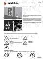
General Information - Safety
Description of Pictograms
Pictograms have been applied on the machine to
explain following situations:
Danger
Obligation
Prohibition
002
Special indications (example: direction of rotation
of the fan, etc)
Many accidents are often caused by the non-observance of the simplest safety rules or poor knowledge of the instructions given by the manufacturer.
To avoid possible danger situations, some of them
are highlighted through special signs represented
by suitable standardized symbols (pictograms).
209a
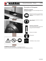
Below is the list of the most common symbols applied to our machines:
109
Warning !
Risk of high temperature surface
(> 70 °C)
106
Warning !
The machine is with remote control or with automatic system and
may start without notice.
108
107
105
Danger pictograms
These triangular signs are framed in black with a yellow background and the symbol is black.
Warning !
Vessel under pressure.
Warning !
Air delivery.
Warning !
Risk of electrical shock.
Prohibition pictograms
These circular signs are framed in red, with white background and the symbol is black.
No voltage.
112
No pressure in
the receiver.
111
110
No working on
the machine.
TI010G0021
1)
7%.0.8
<!
;
9
#J= !
54 33% 464 9% 93B6 5 4809% 4 251
5 434 0% 9.
386 8 5
0351
4 ?% 3? 04
64 41
7 !
54 464 08 ?8 45 58 6? 4.% .01
3 . 1
.61
449%8 38 J941
J ; !
5 9? 452 309 . 3604 04-
@6 G %4 . 5 43 % 9. 46 8 3?81
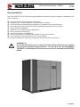
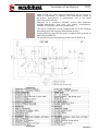
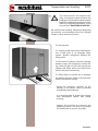
Description of the Machine
3.01
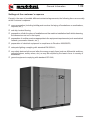
Mattei Series rotary electro-compressors are the result of
years of investments in research and development aimed at
the gradual improvement in performance and at the same
time environment-friendly.
Designed for a continuous industrial service, they guarantee
constant performance over time, low energy consumptions,
reliability, functionality, and easy maintenance.
The electro compressor comes complete with all of the elements
described below and equipped with optional devices.
Unless differently required, the group is supplied with synthetic oil
Mattei Rotoroil 8000 F2.
For special lubricant requirements, please refer to Section 8.
TI010G0021
43.535
1
%% 304 3%4 4.6 38 45 4%% +8 2 % 25
6 .44 0%1
5 38 54 .% ?
B . 644 3%4 5 065
0%8 3%6 5 4 .%1
@ 359% %4 56
4 %%2 48 3344 . %%1
5 94 54 64 %%2 48
%.6 5%6 . 5 3044
# 3 ,$1
3B6 3%4-.+6 2 %%43? %85
3? 39 9+1
!
5 ? 3044 4 ?%03 8 30441
3444 . 38% #4$ 2535 0 333%%8 6% 25 4
2 3?41
5 54 %6% 4%4 2535 5 ?4 4%1
5 ?4 45 64 5 4 98 3.6% .31
%6 . 5 0?6 4 3%6 %93 ? 98 ..3 J3 . %
565 4 5 44 ..3 92 5 3044 3509 5 %
3?1 0 . .% 33% 4 1
% .%0 5 4.3 . 5 4 ?4 3 33 . 5 0?6 4 ?4
8 21
5 ? 3044 5 +% 544 456 5 64 5 3?41
5. 5 4 . 54 9641
5 4 4 98 25 0% 964 5?6 33%%8 %0 %.01
5 2 .4 444 565 .% 5 565 5 0%6 ?%?1
5 34 ?%0 . 5 3B4 .0 98 5 4 ?4 34 34
%4. 30441
` >=>
5 B ?%? ? 98 43.3 4??%? 565 58%3 33 46 5 40 % 4
4 . %93 J44 5 B :8 5 4840 :041
{
|
}
~
.%
03 B ?%?
% 3509
044 3509
% .%
I%4
%436 4
E% 3% #$
43.535
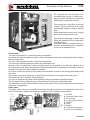
3.03
F
Minimum pressure and non return valve
Compressed air is delivered by the compressor through a valve
ensuring a minimum pressure inside the oil chamber, so as to
guarantee smooth operation when the compressor is delivering air.
This valve also prevents the compressed air in the system from
returning to the compressor.
Oil separation
The air/oil separation occurs in different stages and ensures
exceptionally low oil consumptions.
The main mechanical separation occurs in the oil chamber through
a labyrinth path.
This mechanical separation works via the continuous changes of
direction of the air flow in the labyrinth path.
The last separation occurs through the coalescing filter, removing
the remaining oil vapours from the air.
This particular oil separation system brings to a very reduced oil
consumption. The large size of the filter and quality of materials
ensure a long life of the filter itself.
Electric Motor
The compressor and the motor are connected by means of flexible
coupling. This ensures a perfect alignment, no power absorption,
silent operation and no need for maintenance.
The electric motor is asynchronous, threephase, 4 poles, with short
circuit winding.
- Class F isolation
- High Efficiency Class
- IP 55 protection degree
- Power supply according to IEC 38 standard.
- Voltage/Frequency V 230/50 - 400/50 Hz - V 230/60 - 460/60 Hz
Cooling Systems
The compressor comes with two aluminium radiators and suitable
for cooling oil and compressed air, respectively.
An airflow, output from the fan inside the sound poof cabin, comes
into contact with the radiators and removes the heat generated during compression.
The temperature of the output compressed air is slightly higher that
the environmental temperature.
See technical characteristics attached.
TI
43.535
3.04
('
Electrical Starter
The protection class is IP 65, and it includes
- Star-Delta starter
- Main motor protection (by thermal probe=PTC)
- Fan motor protection (by magneto-thermal switch)
- 110 V transformer for auxiliary circuits
- 24 V transformer MAESTRO xs control device
- Protection fuses for auxiliary and primary circuits of transformer
- Terminal board for the remote restarting of start/stop controls and
signals
- Emergency push-button
- Micro-door
- Safety block:
for high temperature in the compressor, motor overload, oil low level,
insufficient ventilation, air and oil high temperature, emergency stop,
clogged separator filter, failure in the pressure sensors
The Diagram is contained in a specific document holder pocket.
Separator Tank
5B30425
7
545%9B.9.84.5
B14%430425*K 5
%%84450353%56%041
5B49%33044%13444
253092543.3.%6%044.%1
%284345%64%6.03341
0.3445%?90554B44%
%254650351
50+006440.54B
452535%1
546.54.8?%?6450+00%
6441
5B54946045644
.%6.01
44452564%+53B44549.
4648449%341
404350355494%%4
5445%:44840353B985.541
4346460659:985..
%%241
TI
851
Description of the Machine
3.05
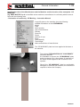
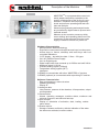
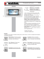
MAESTROxs is a programmable control unit
which adapts compressor operation to the
specific requirements of the air line it is connected to. It features various programming
levels and performs operating and fault controls and analysis.
Advanced programming and analysis levels
are protected by digital codes to prevent unintentional access.
Maestro xs also contains a memory which
saves settings and operating data even if the
compressor is disconnected from the power
supply or switches off due to a power cut.
Hardware Characteristics
- Microprocessor-based technology
- Ergonomic control panel with rapid access keys to main menus
- Access keys to menus, start/stop and reset keys with Ledcontrolled indications
- “LCD” display – text with blue leds - 8 lines - 22 types
- 24 V AC 50/60Hz Power Supply
- 24 V dc Digital Inputs
- Digital output with clean contacts up to 230Vac and until 24Vdc
- Analogue output 0-10 Vdc
- Pressure analog signals (4-20mA)
- Temperature analog signals (NPT)
- Interfaces:
❏ RS485 to communicate with other “MAESTRO xs” devices
❏ RS485 (optional) to communicate with supervising PC and lan
Software Characteristics:
- Easy use based on a menu structure
- Updating possibility
- Display of :
❏ Analogue data:
- Line pressure, pressure in the chamber, oil temperature, output
air temperature
❏ General data:
- Alarms, operating messages, machine status, maximum and
minimum pressure, last start and last stop
❏ Hour counter:
- Display of schedules of activation, start, loading, maintenance warns
❏ Events archive:
- Storage of alarms and blocks, with the indication of the when
the alarm was activated, machine status.
TI0G00
Description of the Machine
3.06
The device allows for:
- Multilingual user Interface
- Weekly and time schedule of starts and stops
- immediate reading on display of data relevant to the compressor
operation:
❏ Compressor hours of activation and line pressure of the equipment
❏ Pressure oil chamber
❏ Output air temperature and compressor oil temperature
❏ Hours of running and hours of loading
- Programming of basic parameters for optimum operation of
compressor accessible by user:
❏ Control modes of compressor (Local/remote, master/slave)
❏ Operation modes (Automatic, Continuous)
❏ The advanced programming of parameters, protected by
“password” allows the qualified engineer to change those
parameters to which the user cannot access directly
- Checking the input and output status of the gear case to detect
any failure in the compressor electric equipment
- Storage of up to 20 failure events
- The check of the integrated dryer (plus models)
- The remote control by clean contacts of the machine status below:
❏ Activated compressor (optional)
❏ Running compressor (optional)
❏ Compressor under load (optional)
❏ Compressor blocked (standard)
Communication
MAESTROxs, connected to the Mattei supervision device (optional),
allows for:
- Remote monitoring by web interface
- Alarm signaling by e-mail, fax or mobile phone.
WARNING !!!
098
The compressor has been designed to compress AIR ONLY.
!
The compression of other gases is FORBIDDEN.
TI10G00
3.07
43.535
OPTIONALS
50353%49340L3360.
:0498354643.3334444354-
.
Separator and Condensate Drain Kit #5($
Heat Recovery Kit #5 $52.483446
441
5B40.2E%%+3565043?%?
33615B4.530443%6
484034.245634.%2 5
5043?%?%8?4%54331
Water/oil Separator Kit #5$
2
''
',
''
'
1
3
TI010G0021
Description of the Machine
3.0F
_=\
<@
>
!=
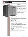
Each AC unit (OPTIMA / MAXIMA) is supplied with a compressed
air cooling radiator. Cooling produces condensation that is
unloaded from specific separators and drainpipes that can be
applied on the front of the machine (see this section Optional
Accessories).
Many industrial applications require that the compressed air be almost completely emptied from the water vapour it contains so as to
prevent any further condensation from forming inside the line pipes
to which it is connected.
Hence, devices that lower the dew point by a few degrees above
0°C should be installed.
In the plus versions the setting up of the machine includes a dryer
with a refrigerator cycle that guarantees an adequate compressed
air quality.
The design of the compressor allows for integrating a dryer with
refrigerator cycle directly installed on the machine.
089
An electronic controller controls the dryer, which manages its
functional parameters according to the different operating load
cycles.
WARNING!!!
For compressors in the plus version see tables
"electricity supply for compressor and dryer" on
page 4.03
<
9=
The product ID plate contains all the machine’s essential data.
Removing or tampering the id plate forfeits the right of guarantee.
!
#!
7
When the compressor is activated, the drier also starts after a preset delay.
381
Alarms are inserted with 5-minute delay to allow the drier to reach
its operating mode.
Once this delay has elapsed, the alarms start and begin monitoring
the system.
Once started, the dryer compressor group stays on until the
following conditions occur:
ᅛ The compressor is stopped with the “STOP” push-button
ᅛ The dryer operating limit conditions are exceeded.
43.535
3.09
The controller manages the dryer operation by monitoring the dew point temperature that allows the
system to run correctly.
The operating limits for such a parameter are as follows:
✔
✔
✔
The dew point temperature > 0°C;
The dew point temperature < 6°C with Ambient Temperature ≤ 25°C;
The dew point temperature < T.amb. – ƒ ambient with Ambient Temperature > 25∞C.
MATTEI sets the ƒ ambient value.
If the dew point drops below 0°C, the controller will indicate the faulty condition [Ice Alarm] while the
dryer compressor is kept active throughout the time corresponding to the parameter [Low Temperature
Delay Time].
Once this time has elapsed, the dryer compressor is stopped so to prevent any ice from forming.
As soon as the temperature rises again above 0°C, the dryer compressor is re-started and the fault
warning is automatically turned off.
Should the dew point temperature rise above the upper limit, the controller will indicate the fault condition [ALARM High Dew Point] for the time that corresponds to the parameter [High Temperature Delay
Time].
When the set time has elapsed, the Alarm warning will stay on.
As soon as the temperature falls again within the above-mentioned operating interval, the fault warning
will be automatically turned off
NOTE:
The user can request Ing. ENEA MATTEI that the fault in the dryer corresponds to a machine BLOCK.
NOTE:
The design of the dryer prevents condensate from accumulating and ice from forming inside it.
In case of any failure in the dryer, by-passing the device is possible by disconnecting the hose linking it
to the air radiator and connecting it directly to the delivery side. All joints installed are equivalent.
DOCUMENTATION
The machine comes complete with:
1 Use and Maintenance Manual complying with Machinery directive )E, E
1 CE Declaration of conformity
1 Start Report
1 Maintenance Sheet
1 Electrical Diagram (inside the control board)
Documents for the optional accessories
CERTIFICATIONS
Ing.Enea Mattei SpA has its company quality system certified according to standard UNI EN
ISO 9001by DNV while the final inspection procedures comply with standard ISO 12171
TI
43.535
1(
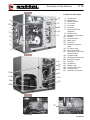
Position of main parts
(
!
,
(
,
((
F
)
(
1
2
3
4
5
6
7
8
9
10
11
12
13
14
15
16
17
'
(,
('
()
(
(F
(!
(
( 18
19
20
21
22
23
24
26
27
044
B.%
%334
%3%
3%
%
3?E*%%
4
%.%%%6
4+43%%
%.%
%%?%4235
0
?8
0044
?%?
%?%?
??%?.%
??%?&..%
4%?%?
%504
%09
%3384%8
.%
%?8
.8?%?
5043?%?
%4?%?
+%8%J3
Pos. 25
Pos. 26
TI010G0021
1((
43.535
=
<
7
#>==
<
!F
45%6
,1(
5 25% . 5 035 5
%6 3%6 5 43 92 5
B6 . 4 04 5
035 4%%6 45% 9 . 43 9.5 .
8 449% <$#+ $1
G
I 3.% 25 5%6 %.6 46
5 035 06 06
564 34 J4 441
* 54 4-
ᆓ ".8 5 % 044 . 5 035 4 .%. 3B : %.6
041 3.3 3604 3 5
%.6 41
ᆓ 5 3 . 6?8 4 5 3%6
92 0 3044M 9. %.
6 353B #%. 5 .0 5 6 J4
4%65%8$ 5 %.6 4 33 5 4 4B . ?61
ᆓ @5 %.6 9 3.% 06
5 96 43 #94$ . 5 035
5 4. 381
6 5 4 3.%%8 .+ 5
035 5 04 4 98 9%3B6
%65284 42841
4 300 3 5 035
.0 0453 64 25 49%
3?61
3B 5 035 98 0?6 5
64 %3 5 .% 98 04
. .B%. 3B 0? 5 %%1
4%%
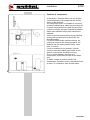
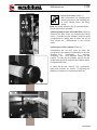
4.02
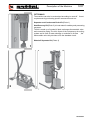
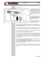
Position of compressor
F
In the section “Technical Data ”you can find the
overall dimensions, the weight,and the cooling
values of the machine.
The compressor must be installed in a covered
and well ventilated area ,away form heat sources.
It can be simply placed on a solid and level floor.
It does not require any type of special foundation.
Space and ventilation around the machine are
essential.
An air-cooled compressor,driven by an electrical
motor,produces heat equal to about 85% the
absorbed power.
For the AC 4000 Series machines,having the
cooling air outlet on the canopy top panel, the
distance from the ceiling should not be lower
than 1,5 meters.
If such a clearance is not possible, a hot air
conveyor must be installed (see further on the
section on ducts size and heat recovery).
The 1,5 meter distance, free from any
obstructions, should be also kept on the intake
end.
To make it easier to perform checks and
maintenance operations on the compressor leave
at least 1,5 m clearance from all other sides.
TI010G0021
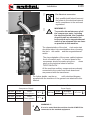
,1
4%%
( Far Electrical connection
()
!F
%8:%.4..45%33
525%33%2B
30%35.3
6%41
WARNING !!!
G
To permit safe maintenance of all
the compressor parts, including
the electrical board, the Customer
should install an automatic line
knife switch and a magnetothermal
switch of an adequate size as close
as possible to the machine.
5353434.5%3 3%04
45%9B34253546
5%B .4235 50650%
42351
54L.52 39%492
%B .4235 53%9.5
304445%90465?
%4
6?5353%45.43
<
<1
('
%%5035+%8304%8
3353%353B9
22554.01
*.5%4454
3.3%33%60 4%255035 56%3554
%1
%0L044
%0L
4433
Compressor Supply
Dryer Supply
'CL
,)"3
)CL
"3
'CL
"3
)CL
.4
Three-phases
#*&$
.4
Three-phases
#*&$
!F
,"3
G
"3
'CL
)CL
.4
#(*&&$
Single Phase
WARNING !!!
It is to be noted that the machine should ALWAYS be
connected to the earthed equipment.
TI010G0021
,1,
4%%
Connection to the air distribution system
Compressed air distribution
%8 :%. 4%
45% 38 5 33
5 49 484
0 30%3 25 5
6%4 .31
5 0 . 496 4 96 30
44 .0 5 035 5 44 25 5 %24 44 68 241
? %444 244 6%%8
353B %% 64 . 5 49 :
0 %% 334441
*%4 6%4 5 33444
45% 6 031
5 336 5 4840 45% 9 .%+9% 25 0 %2 5 5 %?6 5 0351
3 ?%? 4 : 4% 5 035 .0 5 49
4840 34 . 031
WARNING !
The machine is equipped with a NON RETURN VALVE; if the
detect valve is closed when the air distribution is operating
some air under pressure could remain inside the connecting
pipe !
Arrange a draining system for the piece of piping between the
compressor and the detect valve.
In case there is the need to disconnect the machine, ensure
that the internal pressure is exhausted before the dismantling
procedure.
5 035 ? .%+9% 54 .0 5 49 4840
33 9%26 6- 4 . 3 3%6 .
5 5 B .% %% 5 035 3041
5 2 98 30444 34 ?9% :8 6 5 09 34 3 :8 . 2 3 4 %? 5081
. 54 9 3044 4 3% 43.3 2535 %% ?44 . 5 30444 4% 251
%6 34 34 . 6 :8 . 5 2 341
5 34 3 4 4 25 03 ?3 #%$1
Please note that condensate should be collected and eliminated
in compliance with current laws.
TI010G0021
4.05
4%%
Dimensions of compressed air distribution pipings
We mention that the main causes for wastes are pipings with unsuitable diameter and losses
due to an improper setting up of the equipment or deteriorated materials.
The pipe diameter must be duly selected so as to minimize the pressure drop between the
compressor or the storage receiver and the point of use, based on the machine features, like air
delivery and working pressure.
The pressure drop is proportional to the pipe length and most losses occur during the change of
direction (curves, elbows) and in the valves.
With a pipe having the same diameter as the compressor outlet, the length should not exceed
50 m.
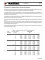
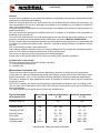
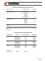
To make a check of one’s own equipment, “Table 1” gives the load losses, over 100 metres
straight piping, according to nominal diameters usually employed and at different air delivery
and working pressure conditions.
A perfect air distribution system should limit the pressure drop from compressor to the point of
use within few tenths of bar.
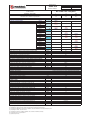
Table 1 – Load losses (bar) over 100 m straight piping
0
*%?8
[m3/min]
PRESSURE
[bar]
1”
1
2
3
4
6
0,087
0,315
0,666
1,134
7
0,076
0,275
0,583
0,993
8
0,068
0,245
0,518
0,883
9
0,061
0,220
0,467
0,795
10
0,056
0,200
0,424
0,722
2”
4
8
16
24
0,038
0,138
0,496
1,050
0,033
0,120
0,434
0,919
0,030
0,107
0,386
0,817
0,027
0,096
0,347
0,735
0,024
0,088
0,316
0,669
3”
8
16
32
64
0,019
0,069
0,248
0,894
0,017
0,060
0,217
0,783
0,015
0,054
0,193
0,696
0,013
0,048
0,174
0,626
0,011
0,044
0,158
0,570
4”
16
32
64
128
0,018
0,064
0,230
0,829
0,015
0,056
0,201
0,725
0,014
0,050
0,179
0,645
0,012
0,045
0,161
0,580
0,011
0,041
0,146
0,528
TI
4%%
4.06
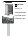
Heat Recovery
As mentioned in the above
section at Page 3.03, a fan
produces an air flow that
cools both the oil and the
compressed air, heating up
when it passes through the
cooler.
F
The recoverable heat represents about 100% the installed power in the AC
4000 S4 machines.
The heat produced can be
conveniently recovered and
used to heat rooms.
Any duct should be adequately sized and, if necessary, shaped in
such a way to allow for a correct use during Winter and the output of
hot air during Summer.
The duct to recover/output hot air should be designed by a competent engineer and should limit the load loss at approximately 20 Pa.
If the duct offers greater resistance, an auxiliary extractor should be
used to prevent any overheating of the machine.
As an example, a duct with a higher or equal section to the coming
out of the machine (the output grid on those versions equipped with
a soundproof case), made up of some 10 m of straight duct and two
90 ° elbows properly connected, allows the maximum tolerated limits
to be maintained.
However, it should be noted that 10 Pa increase corresponds to some
2 -3 °C increase in operating temperatures.
As for the recoverable heat, it should be noted that 1 kW of installed
power allows for the heating up a volume of about 30 cubic meters
by 1 K (1 kW =860 kcal/h).
In the Section on “TECHNICAL DATA ”attached to this manual the
values required to realize that which is mentioned above are indicated.
TI0
'1(
.8?34
EMERGENCY - STOP button
5 035 44 00%8 25 5 9
4 441
G
ჹ
54 9 4 9 4 %4 0638 41
*: 44 . 5 3044 98
04 . 54 9 may damage its
operation1
WARNING
%4 . 5 % .
MAESTROXS % 35 54
%. % 43 .
B84 6006 %% . 4
.341
Safety Valve
<*
K""
> 3453044
34.?44453509 25%
%065?%4246%01
54.8?%?44( 9.C?4
.30444('9.CC?441
Servovalve
I44 5 6 44 3% .0
98 O 30444 . , 4
B 5 0% .. % .34 98
04 . <
"""
>1
54 4??%? %04 5 0+00 6
446
5 0
98 36 5 B ?%? 2535
3%44 4 5 % 44 3441
5 0+00 6 44 4 4 4
0%?% 6 5 .% 43 : 8 .5 J4041
Setting the Servo Valve Maximum Pressures
"4
C
F9
(9
CC
??%?4
(9
Note
044 4 5 4 ?%4M 4 4664 4B
. 0.3 . 464 %8 34
. % 25 B2%61
%8 4B%% 4% 45% 0B
5 461
G
WARNING !!!
DO NOT set the servovalve at HIGHER
values than those used by the
manufacturer, Ing. Enea Mattei S.p.A.
In fact, if the machine works at higher
pressures it requires more power; this
could lead to overheating and machine
shutdown.
TI010G0021
099
Commands and Control
5.02
MAESTROxs is a programmable device to control the
machine that can adapt its
operation to the specific requirements of the network it is
connected to.
851
It has several programming levels, with
special possibilities of control/analysis of
operation and of failures.
The advanced programming and analysis
levels are protected by digital codes so as
to prevent any unintentional tampering.
Maestroxs has a storage that saves the
settings made over time as well as the data
on operation even if the machine is not connected to the electrical line or if voltage drops
occur.
A weekly schedule of starts/stops can be set
that is combined with the management of
the connection to other machines so as to
control any multiple installations as efficiently as possible.
“Maestro xs” is a control device made up
of two separate units:
- Display with keypad
- Data input-output device
Keypad
The buttons are backlit for enhanced clarity and, in some cases, in order to complete the information
provided by the device.
Up button: Moves around the
various menus. Also increases the
value of a variable in the edit mode.
855
852
Reset buttons: Resets any faults
detected by the system. Eliminate
the reason for the fault first.
Enter button: Accesses the selected menu and opens and closes the
memory in the edit mode.
856
853
On / Off button: Enables and
disables the compressor.
Down button: Moves around the
various menus. Also decreases the
value of a variable in the edit mode.
857
854
Esc button: Accesses the main
menu and exits the current menu.
TI0
How to Use the Machine
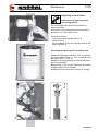
6.01
Foreword
The user should appoint a qualified
person for operation and maintenance
of the machine.
He should properly train all operators,
so that they are acquainted with all
needed measures to prevent any accident or injury to people.
All start and stop procedures as well
as emergency ones should be known;
they should be also periodically
checked with the operators.
The operating and maintenance manual should be always available;
in case of loss or damage, further copies can be purchased from
Mattei’s sales organisation.
Checks before start
Before starting the machine, ensure that:
the electrical system complies with voltage and power of the
machine and that wires are of suitable section;
the machine is earth connected and protected against possible
short circuits;
the mains isolator is installed near the machine;
the machine oil level is correct; with compressor not operating
and without pressure in the chamber the oil should touch the
filling nozzle.
In case of low level, top up with suitable oil of the same type as
in use;
the machine is connected to the compressed air system.
TI010G0021
How to Use the Machine
6.02
Operation Modes
To meet the users’ requirements, Mattei compressors have been designed to work in three main operating modes: Continuous, Automatic and Modulation.
The factory-preset mode is AUTOMATIC. To change the setting please refer to page 6.04 of MAESTROxs
1.1.03 operating manual.
An overview of these three options is given below.
072
Continuous (Cont)
In this mode, the compressor delivers air within a clearly defined pressure range; maximum and minimum values are factory-set by Mattei though they can be customised using the programming functions
in the [User] menu. When pressure reaches the maximum value (Pmax) the compressor is off-loaded
(suction valve closed) and decompressed in order to reduce power consumption. As soon as a request
for air from the network reduces pressure to the minimum value (Pmin) the compressor loads again and
resumes air delivery. The compressor can be stopped at any time by pressing the stop button: the stopping procedure comprises a no-load run phase which lasts for a set time during which the compressor
is decompressed.
Nota
If the unit is enabled with a line pressure greater than the set minimum pressure, the compressor does
not start but waits for the pressure to fall below the minimum value.
073
Automatic (Auto) (Preset Mode)
This mode adds another function to the previous one: the compressor can automatically stop at low or
no air demand conditions. The cycle is the following. When line pressure reaches Pmax, the compressor
is “off-loaded"; at this point, two things can happen:
1. if there is no demand for air it runs no-load for a certain period of time TMV (No-load Run Time) and
stops when this period of time expires; it starts again as soon as line pressure falls below Pmin;
2. if line pressure falls to Pmin before TMV expires, the compressor is “recharged”.
The above operating mode can be combined with a special characteristic of MATTEI rotary compressors, the MODULATION phase.
TI0
How to Use the Machine
6.03
By suitably adjusting the its “servo-valve”, the compressor can modulate before reaching Pmax. This
means that Pmax can only be reached in case of very low or nil demand.
Nota
If the unit is enabled with a line pressure greater than the set minimum pressure, the compressor
does not start but waits for the pressure to fall below the minimum value.
074
Modulation
All MATTEI compressors are fitted with an automatic system for adjusting pressure according to delivery
pressure. The internal pressure of the compressor depends (partly) on line pressure and, consequently,
on the demand for air; when the latter drops or is nil, line pressure and internal pressure increase. In
Mattei compressors, the maximum pressure at which the unit runs no-load can be set (by calibrating a
valve). For values slightly below maximum, the suction valve is only “partially” closed by suitably modulating machine capacity to line requirements. Maximum pressure and values slightly below this define
a field or range which is known as a MODULATION BAND.
This operating mode exploits this potential. The control unit ignores the Pmax and Pmin. settings and
operates the compressor without stopping except in case of an operator command.
Nota
The modulation bandwidth is typically 0.3 bar.
Suppose maximum no-load pressure is set (using the SERVO-VALVE) to 7.3 bar.
- For pressure values lower than 7 bar (7.3 - 0.3 = 7), the compressor delivers 100% of its capacity.
- For values ranging from 7 to 7.3 bar (the modulation band), the compressor delivers less than its rated
capacity, suitable for line demand.
TI0
How to Use the Machine
6.04
859
099
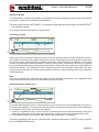
Upon delivery, the compressor is protected by an alphanumerical code which must
be provided by Mattei and entered the first time it is switched on.
The compressor will not work if this code is not entered because, as soon as the
compressor is powered, the screen shown appears with the cursor flashing in the
top left-hand corner.
ENTERING THE CODE
Press < ↵ > to move the cursor to the first digit of the code to enter.
Press <Í> and <È> to select the letters or numbers to enter and confirm with < ↵ >.
The cursor automatically moves on to the next position after each digit is confirmed and, if the code has
been correctly entered, the first page of the menu appears [ MONITOR ].
If the code is entered incorrectly, instead, MAESTRO xs asks for the entire code to be re-entered.
i
After being entered correctly, the code will no longer be requested.
From now on, the compressor can be used and configured.
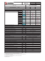
In order to communicate with the user, MAESTROxs features carious menus that allow the compressor
to be monitored and programmed. These are divided by function and not all of them can be accessed
by the final customer. Some of them are protected by one or more passwords.
The menus are divided according to the functions that they control.
The main menus used to manage the compressor are:
Menu
Monitor Menu
User Menu
Advanced Menu
Clock Menu
Log Menu
Network Menu
Info Menu
User access
Yes
Yes
No
Yes
Yes
Yes
Yes
Password
No
No
Yes
No
No
No
No
Menu ID
0
1
2
3
4
5
6
To simplify use of the compressor, some symbols are used to graphically represent certain functions, such
as machine status and other settings.
Other symbols are used to report operating problems, special enabled functions, etc..
The various menus also use texts informing the user of the meaning of the variables and the functions
they perform.
To simplify traceability of a variable, every menu is identified by a number, as shown in table 3. The same
applies to the submenus and individual variables.
For a more detailed description of individual menus, please refer to the Maestro xs manual (code TECA2G-007) supplied with this manual.
TI
6.05
How to Use the Machine
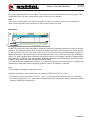
Failures can be divided as follows:
q Failures with an intervention signal (alarms)
q Failures causing the immediate stop of the compressor (blocks).
099
Operational Failures
860
The card signals a failure by lighting of the reset button, together with a visual signal through icons and a
sliding description.
Press the “reset” key once, for more information about the kind of failure occured. A page appears that
contains the information on the failure and specifically:
q
q
q
q
861
The event code
The working time at which the failure occurred
The detailed description of failure to the main compressor (C1)
The detailed description of failure to the additional compressor (C
2) when fitted
q The chamber pressure at the moment of failure
862
All these information are stored in the incorporated historical archive together with other information, and
it is possible to store up to 20 failures
When the failure number exceeds the allowed limit, the system clears the least recent failure to insert the
latest one.
Press ““Reset” key a second time to reset the compressor operation.
098
098
Note : for Plus versions the faults “frost alarm” and “high dewpoint” are visually signalled when the dewpoint
temperature is out of the standard operating range, with automatic restoring as soon as the temperature
goes back to the normal values.
See MAESTRO xs manual (code TECA27007) supplied together with this manual.
!
!
WARNING !!!
If the failure cause cannot be solved, the compressor will not start as the failure appears to be still active and re-displays the intervention request.
WARNING !!!
The rotation in the wrong direction can seriously damage the compressor.
TI0
6.06
How to Use the Machine
863
099
Once all foreseen operations before starting have been performed, and which have
been described in the Sections above, the Maestro page displayed to the operator is :
853
Starting
Press the key to switch the compressor “on”
The led lights with yellow colour.
The compressor is started. It starts off load (intake valve closed) and then goes on load after a pre-set
time, subsequent to the star-delta switching delay
The compressor, from this moment on, delivers compressed air according to the set operation mode.
864
After starting, the page below appears
within few seconds
853
Stop
To stop the compressor, press key
The yellow led of the ON key turns off.
865
The display shows:
The compressor is unloaded (decompressed) for a preset time (basic programming).
After the motor has stopped the residual pressure inside the compressor discharges completely in
approximately one minute.
866
The display will show the following page
TI0
How to Use the Machine
6.07
099
The machine can be restarted according to the above sequence, but it will start again only if
the internal pressure has lowered under the maximum allowed value for the re-start (preset
factory data not changeable by the user)
NOTE
MAESTROXS has a control logic that prevents an excessive number of consecutives
starts.
This logic is cleared by the user ’s manual intervention, if he/she acts directly by turning off
and on the machine manually.
098
WARNING
!
An excessive number of consecutive starts may damage the main motor.
Operate manually only in case of real need and wait for a reasonable amount of time before
restarting the machine.
The number of starts depends now on many parameters,the rated power,the operation cycle,the
working pressure,and the ambient temperature.
For any requirement,please contact MATTEI.
TI0
Maintenance
7.01
Suggestions on maintenance
Machine cleaning
Cleaning of the equipment should be carried out at regular intervals, following the schedule in this
manual.
To clean delicate parts of the machine direct the compressed air jet so that neither machining waste nor
humidity can penetrate in the mechanic assemblies.
Only use lint-free cloths to clean internal and/or moving parts (in contact with lubricant).
Always use perfectlly dry air during the cleaning and at suitable pressure to avoid injuries to the operator.
Maintenance schedule
The time intervals in the maintenance tables are only reference values concerning the machine operation at the company’s conditions.
Environment factors affecting these intervals are mainly: machine environment (temperature, humidity)
and air pollution.
Machine lubrication
Use only the lubricant quantity needed to lubricate the involved mechanism. Carefully dry the excess oil
or grease with a cloth.
Sometimes an excess or a lack of lubricant may jeopardize the machine operation.
Only recommended lubricants or well known and tested equivalent lubricants should be used for lubrication
Replacement of the exhausted oils should be made when the machine is warm. The oil temperature
should range between 25 and 30 °C. (see section 8).
The draining and filling holes should not be left open for more than the time needed to replace the oil.
Jobs to be performed during maintenance
During maintenance operations pay attention to all signs that may precede a failure, and specifically:
• presence of corrosion,
• presence of wear,
• presence of loose unions or connections,
• presence of oxidized contacts,
• after each maintenance operation, exhaust the air from the pneumatic pipings.
Minimizing downtimes after a failure
It should be noted that correctly performed maintenance interventions may minimize downtimes after a
failure.
A repair made in due time prevents further deterioration.
Only use original spare parts and repair the damaged component thoroughly, by your factory or send it
to the nearest authorised service centre.
TI010G0021
3
G
1
Regular Checks
WARNING !!!
After the first 50 hours of operation and every 6 months or 1000 hours:
- tighten nuts and screws fixing the cables in the command and control electrical
board and in the terminal board of electrical motors.
Within the first 300 hours of operation:
- clean the oil return valves (Page 7.04).
Weekly # ?8 ' 54$
53B 5 % %?%
53B % 5 34 4 %?%?.%#25 % B$
Monthly # ?8 54$
% 5 B .%1
% 5 % 3% 5 3044 .3%1
%5.%.543641
Every three months # ?8 ' 54$
% 5 % ?%?4
Every 6 months # ?8 (1 54$
%3 5 B .%
65 4 4324.+6524
4543%%4
500%91
74509641
G
G
Yearly # ?8 1 54$
%3 5 % ?%?4
Oil change
Rotoroil 8000 F2-
?8 ( 054 '1 54
Rotoroil 8000 F4-
?8 ( 054 '1 54
Rotoroil 8000 FG-
?8 ( 054 (1 54
At each oil change, replace the oil filter.
WARNING !!!
48 ?04 E 565 04 03 4 45% 9
3 0 .:%81
The manufacturing date is quoted on rubber hoses.
Their operating life span is 3 years, after which they should be replaced.
WARNING !!!
?? 03 604 ?%9% 5 5% 5 4 0 5 035
5 94 2B6 ..338 31
%4 . Ing. ENEA MATTEI S.p.A. E M.T.A. . .5 %41
G
WARNING !!!
Kits with components for preliminary maintenance are available.
Please apply to M.T.A. for further details.
G
WARNING !!!
For compressors equipped with INVERTER, before performing any maintenance job,
wait at least 5 minutes after you have disconnected the electricity supply.
TI010G0021
7.03
Maintenance
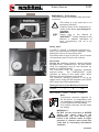
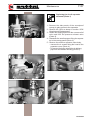
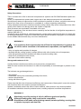
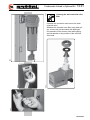
Check of oil level (Photo 1)
With compressor not operating and
without pressure in the chamber the
oil level should touch the filling
nozzle.
Note: the visual indicator (fig. 4) is placed where
the oil level switch operates.
Cleaning/replacing the air intake filter (Photo 2)
Remove the filter cover, by releasing the fixing
hooks. First take out the element, clean by using
compressed air, taking care to direct the air jet
from inside out. Reassemble in the reverse
order.
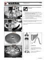
Cleaning the oil/air radiator (Photo 3)
1
Considering the air flow used to wash the
compressor, the radiator is crossed by an air flow
directed from
downwards
to
upwards.
Therefore the dust deposits mainly on the
bottom. To clean the oil radiator, remove the fan
guard panel (photo 4) and blow the radiator with a
compressed air flow.
To clean the air end, remove the soundproof
panel and proceed as above, by blowing the
radiator by means of a compressed air flow.
2
3
4
TI010G0021
((
Maintenance
7.04
Cleaning the prefilters
The machine is equipped with a
prefilter to remove dust and is
articulated by the intake air.
The prefilter is composed of a metal frame
containing a filtering wire mesh.
It slides on metal guides in the side panel and should
be removed from its housing for
replacement or cleaning purposes.
'
It filters the intake air and washes the compressor
while preventing foreign particles from entering the
machine.
Frequent cleaning of panels is essential.
To do this, open the door through the fixing lock,take
out the panel and blow out with compressed air.
The synthetic material can be washed whenever
necessary.
,
No solvents should be used for the washing.
TI010G0021
1'
3
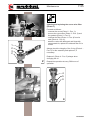
Cleaning and replacing the servo valve filter
(Photo 1)
1
(
2
34.%%24432 5 432 #5 41($M
0? 5 33 #5 41$
5 64B4 #5 41 $M
432 5 .% #5,41,$.0 4
4 #5,41)$M
245 5 ?%? 25 6 9%2 25
3044 M %3 5 4 .% . 4
.%1
%284 353B 5 68 . 5 6 #5,
41'$. 5 4409%8 %3 .
34481
%3 #5,41'$%284 25
3566 5 %1
5 ?8 ' 54 .
1
,
'
)
3
4
TI010G002
7.06
((
Maintenance
Replacing of the oil filter
Replace the oil filter every time
you change the oil.
Do not discharge the oil from the machine to
replace the filter.
Just wait for a few seconds after the last stop to
enable the oil in the tubes to flow.
Proceed as follows unscrew the filter cartridge#5($
clean the seatM
wet the gasket of the new cartridge with oil and
screw it#5 $1
) 1
Cleaning and replacing the servovalve filter
Detach the supply pipe (Photo 3 – Pos. 1), unscrew
the upper elbow (Photo 4 – Pos. 2) and take out
the filter (Photo 4 – pos. 3).
Replace it if proper cleaning of the filter with detergent is not possible.
Reassemble in the reverse order and use proper
sealing material for the threads.
Replace the servovalve filter at every oil change.
(
2
2
3
3
(!
(F
1
4
TI010G0021
1
3
Replacing the air-oil separator
elements (Photo 1)
1
( 0? 5 4 %4 . 5 4.
38 6 3344 5 41
0? 5 " 4 452 43 <"
%6 %30>1
35 5 4%8 4 .0 5 ?30 %.
?%? .0 5 44 +54 ?%?
#5 $1
, 40% 5 40%% 4:4 .+6 5 4
5 38 % #5 $1
' 0? 5 000 44 ?%? 98-
432 5 , 4324 .+6 5 5 5
4 3? #5 ,$1
0? 5 98 +3 5 %?8
.0 5 546 #5 '$1
3
2
4
5
TI010G002
1F
3
Replacing the air-oil separator
elements
(
1
432 5 3? .+6 4324 #5 ($1
F 0? 5 .+6 4324 +3 . 5
2%% 3 4 3? 1
! 5 3? 4 452 5 B6
3 06 5 6 #5 $1
( 432 5 %04 #5 ,$ B 50
.0 5 41
(( %3 5 %04 #5 '$
3 5 ?4 . 5 4409%6 25%
?.86 5 3 . 5 61
- .%%8 65 5 3? 4324 25 =60 :1
2
3
6
ATTENTION
5 % 452 5 )
%%24 . 4 0?%
. 5 3?1
5
%4 33 MTA . 6 5 %1
4
TI010G0021
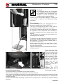
Maintenance - Oil change
7.09
Foreword
As mentioned before, the oil performs
many essential functions for compressor operation and, consequently, it is
important to check its quantity and
conditions at the suggested times.
Please refer to the specific tables to choose the
most suitable oil types for the different operating
conditions.
1 1
First oil change
If not differently stated in the nameplate, the compressor is supplied with Rotoroil 8000 F2 oil.
The first oil change and the first oil filter change
should take place within 5000 hours or one year.
It should be noted that exhausted oil is dangerous
for operation of the compressor and, therefore, it
should be replaced when the change interval has
expired.
The oil should be replaced with the machine not
operating and with warm oil.
To drain the oil, wait until the compressor is no more
pressurized, checking that the pressure gauge on
the separator or on the receiver indicates there is
no more internal pressure.
Slowly unscrew the filling hole plug (Photo 1) and
check if there is any foam; wait for some minutes
until the oil demulsifies.
Open the drain plug (Photo 2) and drain the oil into a
suitable container.
2
3
4
4
Close the drain cock
upon the operation end.
Fill the oil chamber with
new oil to lap the gate.
Replace the plug gasket and tighten it well.
Start the compressor
and let it run for some
minutes, then stop it,
check that the oil
reaches
the
filling
nozzle and top up if
necessary.
Note:
the
visua
indicator (fig. 4) is
placed where the oi
level switch operates.
Use of Rotoroil lubricants
It is recommended to use Mattei Rotoroil 8000 lubricants.
Successive oil changes can be made at the scheduled intervals.
If the machine has already operated for a long period with other lubricants and there are traces of sludge
or deposits, it is suggested to wash with Rotoroil 8000 F2/F4 for about 200 hours, so as to remove all
residual impurities.
It is also recommended, when filling up with new oil, to replace the oil filter and the separator filtering
elements.
TI010G0021
Lubricants
8.01
Lubricants are flammable products.
Observe the indications given on the containers !
During the disposal of exhausted lubricants it is necessary to comply with following environment protection rules:
• Lubricants may contaminate water and soil !
Never pour lubricants on the ground, into water, or in the sewerage system.
Any infringement of these rules can be legally prosecuted! When handling lubricants keep an oil agglomerative base near the working area.
• Recover the exhausted lubricants while separating the mineral based from synthetic lubricants. Upon
disposal, please comply with current regulations concerning the disposal of exhausted oils.
Only the use of lubricants with suitable quality guarantees a safe operation of the machine.
It is forbidden to mix lubricants of a different quality, as their composition and additives are not
the same.
This rule should be mainly applied to synthetic and mineral lubricant mixtures.
If other lubricants are to be used, it should be verified beforehand if the two products are compatible.
In case of doubts, the lubricant used up to that moment should be completely eliminated, by means of a
washing procedure of the fluid circuit.
To avoid any risk of contamination, the lubrication procedures should be carried out under “absolute
cleanliness” conditions.
All manufacturers of lubricants mentioned in the table offer a technical information service that may
answer all your questions on lubrication.
WARNING on lubricants
The correct use of suitable lubricants considerably helps to obtain the maximum performance and the
elimination of failures.
During the handling of lubricants on equipments, it is essential to strictly comply with the following
precautions, for sanitary protection:
• Avoid any prolonged, excessive or repeated contact of the skin with lubricating products as well as
avoid inhalation of their vapours or fumes.
• Wear suitable clothing and protections to protect the skin (for instance overalls, eyeglasses or, as far
as allowed by the safety rules, protection gloves) or apply a protective product.
• Clean dirty skin carefully by abundantly washing it with water and soap.
• Apply a skin cream after washing.
• Take out and change clothes and shoes soaked with oil.
• Never put oil soaked cloths in one’s pockets.
8.02
Lubricants
General
Several oils are available on the market and research continuously improves their characteristics and it
changes the names and specifications.
When the warranty period is over, during which the use of Mattei Rotoroil lubricant is compulsory, the
user can decide to use the oil he believes most suitable or the available one, provided it is suitable for
rotary vane compressors.
Only manufacturers of lubricants can recommend the most suitable oil for the kind of machine and for its
specific application.
The user should then purchase the lubricant from an oil company or a distributor that guarantees its
suitability for the specific use.
The cost of the best lubricant is a small percentage of the total running cost of the machine: it is suggested to purchase the best available on the market (see the section “MATTEI LUBRICANTS”).
Please consider that in lubricated and injection cooled compressors the oil performs the listed tasks and
it is subject to continuous working cycles; therefore, it should be highly resistant to oxidation to ensure
long life.
The oil should also provide a good demulsivity.
Anti-oxidizing additives should provide low volatile substances at the compressor operating temperatures, so as to ensure protection between one oil filling and the other.
The user must adopt the kind of oil grade recommended by Mattei.
Please refer to the specific table for the choice, according to the operating conditions.
Available oils on the market
There are several kinds of oils on the market, including:
❑ mineral based industrial oils;
❑ synthetic oils.
Mineral based industrial oils
These oils have been designed for different applications and also for some types of compressors.
In this case, too, there are standards specifying their features; please refer to DIN 51506 which classifies the oils as VB-L, VC-L e VD-L, according to their possibility of working at different temperatures.
The latter is suitable for high temperatures and it is resistant to oxidation caused by the continuous
mixing with the air.
ISO 6743-3 classifies oils based on the operating temperature and pressure and, according to this
rule, for rotary vane compressors ISO-L-DAH o DAJ oils are recommended, which are for medium and
heavy applications.
The table indicates some typical values of the main characteristics.”
Typical featuress
of Industrial Oils
Measuring
unit
Ambient temperature
5 ÷ 40
Viscosity ISO VG
---
150
100
Viscosity at 40°
Viscosity at 100°
cSt
cSt
135 ÷ 165
14 ÷ 16
90 ÷ 105
10 ÷ 12
93 ÷ 100
-10 ÷ -5
230 ÷ 265
100 ÷ 110
-15 ÷ -10
250 ÷ 265
880 ÷ 900
880 ÷ 900
Viscosity Index
*%45 V.A.
Volumes mass
°C
°C
Kg/m3
Ambient temperature
-5 ÷ 30
Values in the Table are merely indicative
TI010G0021
8.03
Lubricants
Synthetic oils
!F
Many synthetic oils with different basis are available on the market (esters, glycols, etc) that sometimes
have proved to be suitable and provide a longer life than mineral oils.
Normally they reduce carbon deposits, provide a high self-ignition temperature and are remarkably
resistant to oxidation.
As synthetic lubricants are good detergents, to change the kind of lubricant in a machine and pass from
a conventional mineral based to a synthetic one, it is necessary to carry out a thorough washing, following the supplier’s instructions, to avoid damages to the machine if dirt, residues and deposits circulate.
It is also necessary to pay attention to condensate, as usually synthetic lubricants are more sensitive to
water washing and their thin film may not provide enough protection against rust.
This problem can be worsened if the compressor is not working continuously, but occasionally.
In this case, even though not suggesting its use, any responsibility for the choice is up to the user and to
the lubricant supplier.
G
WARNING !!!
It is difficult to determine life of an oil, as there are different parameters affecting the same, among which the operating temperature and quality of the intake
air are very important.
For this reason it is recommended to obtain precise guarantees from the supplier, validated by the analysis of samples taken from the machine, to determine
the suitability of lubricant and its life.
MATTEI LUBRICANTS
Considering the important role of lubricant for operation of the compressor, Mattei offers special lubricants to the users and recommends their use.
These are:
- Mattei Rotoroil 8000 F2 (synthetic),
- Mattei Rotoroil 8000 F4 (synthetic),
- Mattei Rotoroil 8000 FG (synthetic, non toxic)
available in 2, 5 and 25 litres cans.
Their life can reach the hours shown in the table, depending on the operating temperature and conditions of the intake air.
MATTEI LUBRICANTS
Name
Ambient temperature
%F*
%F*,
%F*7
*0('°&,'°
*0°&°
*0'°&,°
Operating hours (max.)
'
'
(
TI010G0021
8.04
Lubricants
Safety Precautions
There is a latent risk of fire in almost all compressed air systems and ISO 5388 Standard explains the
reasons.
In fact, in compressed air systems both oxygen and oil are always present and are combustible.
Should for any reason oil vapours form, these could burn in presence of a flame; an ignition source may
start a fire in case of use of excessive or unsuitable oil, or when neglecting maintenance.
Faulty maintenance has been mentioned, because a dirty radiator may cause a temperature rise, often
quickly, which leads to oil damage and to the creation of deposits.
Such processes are accelerated if unsuitable oil is used.
Based on experience, fires are almost never caused by the fact that the oil self-ignition temperature is
reached (340-400 °C).
Usually the cause is that the oil, while decomposing, creates carbon residues that when in contact with
air and high temperature, continue to oxidize and, under special conditions, may ignite. So it is essential
to use suitable lubricants and carry out correct maintenance.
!F
WARNING !!!
G
It is opportune that to prevent the risk of fires the best attention is given to the
oil choice and to execution of all maintenance operations, and specifically:
- carry out regular and complete oil changes;
- ascertain that the coolling system is always efficient, with often checks to the oil temperature;
- verify that protecting devices installed are always in perfect working order;
- keep the oil consumption under control;
- take care of the machine cleaning.
Storage and treatment of oils
Usually lubricant containers are built so as to prevent any contamination.
When the user receives the lubricant, it is under his responsibility to avoid damages or pollution to the
same.
The lubricant may get damaged due to:
- dust and dirt;
- condensate, mainly due to absorbing humidity from the air;
- extreme temperatures;
- mixing with other oil types.
Please note that dirt in the oil reduces its efficiency and causes wear of those parts it comes into contact
with, therefore there is the need to increase maintenance.
Instead, condensate cancels the effect of some additives, often present in very limited quantities.
Oil containers should be stored in protected rooms, avoiding exposure to extreme temperatures.
!F
WARNING !!!
G
Absolutely avoid the mixing of oils of a different grade and quality .
Although looking alike, they could not be compatible.
Also beware of oil leaks, not only being a waste, but also polluting, causing falls
or injuries to people and also fires.
TI010G0021
Troubleshooting
9.01
General
As mentioned in the section dedicated to protections, the command and control board controls the
smooth operation of the compressor. It is possible that, due to the incorrect use of the machine, or incorrect maintenance or unforeseen conditions, etc., malfunctions occur and that
only their effects are indicated. The table below aims at helping the operator solve some difficulties
should they arise while indicating their possible causes.
Problem - Cause - Solution
Below some possible failures are indicated with their causes and how to identify the correct solution.
PROBLEM
CAUSE
A. Start
MAESTRO+4 works, start is allowed The electrical supply is not sufficient and
the excessive voltage drop during the
but the star/triangle commutation
starting causes release of the contactor.
does not take function correctly
MAESTRO+4 works, it enables the
4by turning green LED on, but
5compressor does not start.
Pressure inside the compressor is higher
than the maximum tolerated value for the
start: or for an abnormal return of the
network air, or because the pressure
transducer reads an incorrect value.
SOLUTION
Check correct sizing of the electrical
supply. Please refer to section 4 of the
supply.
Contact the nearest authorised service
centre.
Check the inner pressure on the pressure
gauge of the separator body and compare
it with the value given by MAESTRO+4.
Verify the correct operation of the pressure
detection system: transducer, collector and
switching solenoid valves.
Contact the nearest authorized service
center.
The hour programming has been enabled.
The compressor runs within a network with
other compressors.
B. Pressure
The system pressure does not
reach the required value.
The servovalve has not been set correctly.
The condensate drain solenoid valve is
blocked in the open position (Optional kit
separator/condensate drain).
The minimum pressure valve does not
function correctly.
Clogged intake filter.
The inside pressure exceeds the
set value .
Verify the setting.
Contact the nearest authorized service
center.
Clean the specific filter to remove the
cause of the block and then check
operation.
Please refer to the “Installation, Use, and
Maintenance Manual”, Section 12.
Check operation.
Contact the nearest authorized service
center.
Replace the filter.
Refer to section 7 to the “Operating and
maintenance manual ”.
Request for air greater than the
compressor maximum capacity.
Please refer to the Sales Organization of
Ing. Enea Mattei S.p.A. to study equipment
improvement..
The servo valve has not been gauged
correctly and/or the setting of the
maximum pressure value in the [
] menu is incorrect.
Check the servovalve and its correct setting.
Refer to sections 5 and 6 of the “Operating and maintenance manual ”.
TI
Troubleshooting
9.02
CAUSE
SOLUTION
The oil return valve filters are clogged.
Replace filters and verify the causes of
the clogging.
(see Section 7)
D. Temperature
The compressor stops due to its own
over-heating.
The radiator or the cooling air filter are
Dirty the ambient temperature is too
hight for compressor operation.
Replace the filters and verify the causes
of clogging.
(see section 7)
The compressor stops due to the
over-heating of the motor.
Excessive working pressure.
Verify the setting and re-set to the value
foreseen for the machine.
(see Section 7)
The motor cooling is not sufficient;
There is not enough air or it is too hot.
Verify the environmental conditions and
the condition of the filtering panel.
(see Sections 3 and 7)
PROBLEM
C. Oil
Excessive oil consumption; the oil
the level lowers too quickly;
clogged; oil is detected inside the
system.
TI010G0021
The Electrical Motor
10.01
General
The electric motor characteristics are given on the nameplate fixed to the motor itself, and specifically:
1. Model
2. Serial number
3. Protection degree
4. Insulation class
5. Maximum ambient temperature
6. Service
7. Service factor
8. Supply voltage
[V]
9. Frequency
[Hz]
10. Speed
[rpm1]
11. Power
[kW]
12. Power factor
[cos ϕ]
13. Rated intensity
[A]
14. Motor weight
15. Type of bearings (front and rear)
Lubrication
The same plate also indicates the type of bearings mounted, for which it is recommended to use lithium
based grease for lubrication.
Greasing (where necessary) should be carried out when the motor is running.
The lubrication intervals should never be longer than the solar year.
Cooling
The motor is equipped with a cover and fan, to guarantee proper cooling. Check that dirt does not form
on this cover as it could reduce the cooling air passage.
Abnormal noises
Any vibration or abnormal noise is usually due to deterioration of the bearings. In this case it is recommended to replace the bearings rather than risking more serious problems to the motor or the machine.
098
Electrical checks
If the machine has been stored for a long period or in case of long stops in damp places, it is suggested
to measure the winding insulation value by applying 500 V d.c. voltage for 60 seconds.
The insulation should be at least 10 MΩ (MegaOhms) in warm conditions or 100 MΩ in cold conditions.
Should these values not be detected and in case the motor has been exposed to damp, it is suggested
to dry it for 24 hours in a furnace at 100-110 °C.
If no furnaces are available, please contact the manufacturer.
!
WARNING !!!
Before starting the machine, verify that the nuts locking the terminals of the
power supply wires are well tightened.
TI010G0021
Storage - Decommissioning
and dismantling
11.01
Storage
The compressor is protected against corrosion and deterioration for the shipment period and for a relatively short period of storage (3 months).
For longer periods please contact the manufacturer considering it can be maximum time 24 months.
In any case it is suitable to keep the machine in a dry place, protected against atmospheric agents.
In wet climates, to protect the electrical and mechanic components the machine should be kept in a
heated room or closed in a barrier- bag with heaters or light bulbs.
Specifically for the motor, please refer to what mentioned about the winding insulation.
Decommissioning
Decommissioning the machine does not involve any special precautions, only collection of the oil contained in the machine and components of the lubrication system, like the oil filter and the oil-air separators.
!F
WARNING !!!
G
Both these elements and the oil should be collected and dumped in compliance with
the current regulations on the environment in order to avoid any pollution and danger
of fire.
Dismantling
When the machine has reached the end of its technical and operating life, it can be demolished, i.e.
decommissioned and put in such a condition so as not to be used any longer for the purposes it was
designed and built, with the possible recycling of raw materials.
NOTE
Ing. ENEA MATTEI S.p.A. will not take any responsibility for damage to people or objects that may
derive from the recycling of individual components of the machine, for operation or assembling situations different that the original ones.
Ing. ENEA MATTEI S.p.A. refuses any implicit or explicit acknowledgement of suitability to specific
purposes of the machine components re-used after the final dismantling in view of its demolition.
WARNING
The deactivation and dismantling of the machine should be carried out only by duly trained and equipped
staff.
Act as follows to deactivate the machine permanently:
❍Drain the oil from the receiver.
❍Disconnect the machine from the electrical and pneumatic supply systems.
❍Lift the machine with suitable lifting means.
❍Disassemble the machine main components.
❍Block all the machine moving parts.
❍Take all the machine components in supervised dumps.
Residual risks after deactivation
After deactivating the machine, there are no residual risk if all moving parts have been duly blocked.
TI010G0021
((
Condensate Unload in Optional Kit
12.01
Cleaning the drain solenoid valve
filter
,
'
Unscrew the connection and remove the drain
solenoid valve.
Withdraw the solenoid valve filter using beak pliers, remove any dirt and wash with detergent.
Re-assemble in the reverse order while paying
special attention to the position of the solenoid
valve seal.
TI010G0021
Form to request Technical Service
Corso Italia, 47 – 24049 VERDELLO - ZINGONIA (Bergamo) - Italy
TEL: +39 - 035/4186400 (Ric.Aut.) FAX: +39 - 035/4186490
e-mail: [email protected]
C.P. N° 69 Zingonia
Company
Address
Please note our request for intervention for our machine:
Serial Number
Modell
Intervention to be carried out at :
Contact Person
Telephone
Failure
Description
Electrical
Mechanical
Notes
Place
Date
Stamp and Signature
TI
Form to request spare parts
Corso Italia, 47 – 24049 VERDELLO - ZINGONIA (Bergamo) - Italy
TEL: +39 - 035/4186400 (Ric.Aut.) FAX: +39 - 035/4186490
e-mail: [email protected]
C.P. N° 69 Zingonia
Company
Address
Please note our order no.
of
with required delivery on
for our machine :
Serial Number
Model
Reference
Description
Quantity
Notes
Place
Date
Stamp and Signature
TI
Parts to be replaced during maintenance
Maintenance Kit
COMPONENTS
QUANTITY
Air filte(
Oil return valve filter
1
O-ring
1
O-ring
1
Element
1
Servovalve filter
1
Separator air kit
O-ring
O-ring
1
O-ring
16
Element
8
O-ring
1
Prefilter
1
Note: please contact M.T.A. S.p.A. to obtain the codes of kits for preliminary
maintenance.
Lubrificanti Mattei ROTOROIL 8000
COMPONENT
CODE
DESCRIPTION
QUANTITAY
Oil F2
BCL06FC002
BCL06FC005
BCL06FC025
Can
Can
Can
2 liters
5 liters
25 liters
Oil F4
BCL06SC002
BCL06SC005
BCL06SC025
Can
Can
Can
2 liters
5 liters
25 liters
Oil FG
BCL06AC002
BCL06AC005
BCL06AC025
Can
Can
Can
2 liters
5 liters
25 liters
M00566
Cartridge
___
Grease for
motor bearings
TI
DESIGN DATA
SERIE 4000
SCHEDA TECNICA
AC 55 - AC 55 plus
TYPE / TIPO
VERSION / VERSIONE
Air end nominal pressure
[bar(g)]
Pressione nom. unità di compressione
L
H
HH
7,5
9,5
12,5
-
-
-
-
PERFORMANCES / PRESTAZIONI
bar (g)
Air delivery / Portata effettiva
Terminal power / Potenza ai morsetti (2)
[l/min]
[kW]
[l/min]
[kW]
[l/min]
[kW]
[l/min]
[kW]
[l/min]
[kW]
[l/min]
[kW]
[l/min]
[kW]
[l/min]
[kW]
[l/min]
[kW]
[l/min]
[kW]
[l/min]
[kW]
Off load power / Potenza assorbita a vuoto
Sound pressure level (3) (6) / Livello pressione acustica (3) (6)
REFERENCE CONDITION / CONDIZIONI DI RIFERIMENTO
Intake pressure / Pressione d'aspirazione
Intake temperature / Temperatura aspirazione
Relative humidity / Umidità relativa
Nominal motor speed / Velocità nominale motore
ELECTRICAL CHARACTERISTICS / CARATTERISTICHE ELETTRICHE
Motor rated power / Potenza nominale motore
Voltage (4) - Frequency / Tensione (4) - Frequenza
Enclosure-Insulation class / Grado prot.-Classe isolamento
Electric starting / Tipo avviamento
Fan rated power (6) / Potenza assorbita vent. (6)
Auxiliary circuit voltage / Tensione circuito ausiliario
Supply min wire section / Sez. min cavo alimentazione (x 10 m)
TYPE OF REGULATION / TIPO DI REGOLAZIONE
Modulation / Modulazione
On load, off load and stop / Marcia a carico, a vuoto e arresto
On load, off load / Marcia a carico, a vuoto
DRYER / ESSICCATORE (Only Plus / Solo Plus )
Absorbed power / Potenza assorbita
Gas
Nominal dew point / Punto di rugiada nominale
OTHERS / VARIE
Allowable ambient temperature / Temp. Amb. min-max
Outlet air temperature (5) / Temperatura uscita aria (5)
AC / AC plus
min-max oil temperature / Temperatura min e max olio
Cooling air flow rate (6) / Portata aria di raffreddamento (6)
Fan residual head (6) / Prevalenza residua ventilatore (6)
Total recoverable heat / Calore totale recuperabile
Oil system capacity / Capacità circuito olio
Oil carry over / Residuo olio nell'aria compressa
Air outlet size / Attacco uscita aria
Condensate drain outlet size / Attacco scarico di condensa
plus version / versione plus
with condensate sep. KIT (7) / con KIT separ. condensa (7)
Water inlet-outlet size / Attacco ingresso-uscita acqua
With heat recovery kit (7) / con KIT recupero calore (7)
AC / AC plus
LxWxH / LxLxA
AC / AC plus
Weight with oil / Peso con olio
5
6
7
7,5
(1)
8
-
9,5
-
10
-
-
11
-
-
12
-
-
12,5
-
-
18,8
19,3
68
[kW]
[dB(A)]
[bar(a)]
[°C]
%
[g/1']
1
20
0
1500
[kW]
[V/Hz]
55
230/50 or / oppure 400/50
IP55-F
Star delta / Stella triangolo
2,4
110
95 or / oppure 50
[kW]
[V]
[mm2]
[kW]
[°C]
1,65
R 404 A
3
[°C]
+1 / +40
[°C]
[°C]
[m3/h]
[Pa]
%
[l]
[mg/m3]
30 / 20
80÷110
16000
80
~ 95
50
3
Rp 2"
Rp ¼"
I
[mm]
[kg]
(3)= According to PN8NTC2.3 measured at 1m distance / Secondo PN8NTC2.3 misurato alla distanza di 1m
(6)= Frequency 50 Hz / Frequenza 50 Hz
(7)= Optional / Opzionale
8510
68,62
8490
69,70
8460
71,86
8420
74,70
8380
76,92
8370
77,54
19,5
intake proportional valve / valvola aspirazione proporzionale
pressureswitch / controllo pressostatico
pressureswitch / controllo pressostatico
(2)= Whitout dryer power (only Plus version) / Esclusa potenza essiccatore (versioni Plus)
(5)= According to reference conditions indicated / Alle condizioni di riferimento indicate
-
9680
66,36
9650
68,68
9610
71,00
9540
75,25
9500
77,14
9
(1)= According to ISO 1217 (annex "C") / Secondo ISO 1217 (annesso "C")
(4)= According to CEI 38 / Secondo CEI 38
10890
61,87
10820
67,41
10720
72,79
10670
75,34
2 x Rp ¾''
2150 x 1890 x 1200
1580 / 1750
DESIGN DATA
SERIE 4000
SCHEDA TECNICA
AC 55 - AC 55 plus
TYPE / TIPO
VERSION / VERSIONE
Air end nominal pressure
[bar(g)]
Pressione nom. unità di compressione
LX
HX
7,5
9,5
PERFORMANCES / PRESTAZIONI
bar (g)
Air delivery / Portata effettiva
Terminal power / Potenza ai morsetti (2)
[l/min]
[kW]
[l/min]
[kW]
[l/min]
[kW]
[l/min]
[kW]
[l/min]
[kW]
[l/min]
[kW]
[l/min]
[kW]
[l/min]
[kW]
[l/min]
[kW]
[l/min]
[kW]
[l/min]
[kW]
5
6
7
7,5
(1)
10980
66,50
10820
72,10
10725
77,70
10680
80,3
-
-
-
-
10190
74,00
10150
76,00
10110
78,40
10040
83,00
10000
85
-
9
-
9,5
-
10
-
-
-
11
-
-
-
12
-
-
-
12,5
-
-
-
21
20,4
70
[kW]
[dB(A)]
Intake pressure / Pressione d'aspirazione
Intake temperature / Temperatura aspirazione
Relative humidity / Umidità relativa
Nominal motor speed / Velocità nominale motore
ELECTRICAL CHARACTERISTICS / CARATTERISTICHE ELETTRICHE
[bar(a)]
[°C]
%
[g/1']
1
20
0
1800
Motor rated power / Potenza nominale motore
Voltage (4) - Frequency / Tensione (4) - Frequenza
Enclosure-Insulation class / Grado prot.-Classe isolamento
Electric starting / Tipo avviamento
Fan rated power (6) / Potenza assorbita vent. (6)
Auxiliary circuit voltage / Tensione circuito ausiliario
Supply min wire section / Sez. min cavo alimentazione (x 10 m)
TYPE OF REGULATION / TIPO DI REGOLAZIONE
[kW]
[V/Hz]
55
230/60 or / oppure 460/60
IP55-F
Star delta / Stella triangolo
3
110
95 or / oppure 50
[kW]
[V]
[mm2]
Modulation / Modulazione
On load, off load and stop / Marcia a carico, a vuoto e arresto
On load, off load / Marcia a carico, a vuoto
DRYER / ESSICCATORE (Only Plus / Solo Plus )
[kW]
[°C]
2,10
R 404 A
3
Allowable ambient temperature / Temp. Amb. min-max
Outlet air temperature (5) / Temperatura uscita aria (5)
AC / AC plus
min-max oil temperature / Temperatura min e max olio
Cooling air flow rate (6) / Portata aria di raffreddamento (6)
Fan residual head (6) / Prevalenza residua ventilatore (6)
Total recoverable heat / Calore totale recuperabile
Oil system capacity / Capacità circuito olio
Oil carry over / Residuo olio nell'aria compressa
Air outlet size / Attacco uscita aria
Condensate drain outlet size / Attacco scarico di condensa
plus version / versione plus
with condensate sep. KIT (7) / con KIT separ. condensa (7)
Water inlet-outlet size / Attacco ingresso-uscita acqua
With heat recovery kit (7) / con KIT recupero calore (7)
AC / AC plus
LxWxH / LxLxA
AC / AC plus
Weight with oil / Peso con olio
[°C]
+1 / +40
[°C]
[°C]
[m3/h]
[Pa]
%
[l]
[mg/m3]
30 / 20
80÷110
18000
80
~ 95
50
3
Rp 2"
Rp ¼"
I
[mm]
[kg]
(1)= According to ISO 1217 (annex "C") / Secondo ISO 1217 (annesso "C")
(2)= Whitout dryer power (only Plus version) / Esclusa potenza essiccatore (versioni Plus)
(3)= According to PN8NTC2.3 measured at 1m distance / Secondo PN8NTC2.3 misurato alla distanza di 1m
(6)= Frequency 60 Hz / Frequenza 60 Hz
(7)= Optional / Opzionale
-
intake proportional valve / valvola aspirazione proporzionale
pressureswitch / controllo pressostatico
pressureswitch / controllo pressostatico
Absorbed power / Potenza assorbita
Gas
Nominal dew point / Punto di rugiada nominale
OTHERS / VARIE
(5)= According to reference conditions indicated / Alle condizioni di riferimento indicate
-
8
Off load power / Potenza assorbita a vuoto
Sound pressure level (3) (6) / Livello pressione acustica (3) (6)
REFERENCE CONDITION / CONDIZIONI DI RIFERIMENTO
(4)= According to CEI 38 / Secondo CEI 38
-
2 x Rp ¾''
2150 x 1200 x 1890
1580 / 1750
DESIGN DATA
SERIE 4000
SCHEDA TECNICA
AC 75 - AC 75 plus
TYPE / TIPO
VERSION / VERSIONE
Air end nominal pressure
[bar(g)]
Pressione nom. unità di compressione
L
H
HH
7,5
9,5
12,5
-
-
-
-
PERFORMANCES / PRESTAZIONI
bar (g)
Air delivery / Portata effettiva
Terminal power / Potenza ai morsetti (2)
[l/min]
[kW]
[l/min]
[kW]
[l/min]
[kW]
[l/min]
[kW]
[l/min]
[kW]
[l/min]
[kW]
[l/min]
[kW]
[l/min]
[kW]
[l/min]
[kW]
[l/min]
[kW]
[l/min]
[kW]
Off load power / Potenza assorbita a vuoto
Sound pressure level (3) (6) / Livello pressione acustica (3) (6)
REFERENCE CONDITION / CONDIZIONI DI RIFERIMENTO
Intake pressure / Pressione d'aspirazione
Intake temperature / Temperatura aspirazione
Relative humidity / Umidità relativa
Nominal motor speed / Velocità nominale motore
ELECTRICAL CHARACTERISTICS / CARATTERISTICHE ELETTRICHE
Motor rated power / Potenza nominale motore
Voltage (4) - Frequency / Tensione (4) - Frequenza
Enclosure-Insulation class / Grado prot.-Classe isolamento
Electric starting / Tipo avviamento
Fan rated power (6) / Potenza assorbita vent. (6)
Auxiliary circuit voltage / Tensione circuito ausiliario
Supply min wire section / Sez. min cavo alimentazione (x 10 m)
TYPE OF REGULATION / TIPO DI REGOLAZIONE
Modulation / Modulazione
On load, off load and stop / Marcia a carico, a vuoto e arresto
On load, off load / Marcia a carico, a vuoto
DRYER / ESSICCATORE (Only Plus / Solo Plus )
Absorbed power / Potenza assorbita
Gas
Nominal dew point / Punto di rugiada nominale
OTHERS / VARIE
Allowable ambient temperature / Temp. Amb. min-max
Outlet air temperature (5) / Temperatura uscita aria (5)
AC / AC plus
min-max oil temperature / Temperatura min e max olio
Cooling air flow rate (6) / Portata aria di raffreddamento (6)
Fan residual head (6) / Prevalenza residua ventilatore (6)
Total recoverable heat / Calore totale recuperabile
Oil system capacity / Capacità circuito olio
Oil carry over / Residuo olio nell'aria compressa
Attacco uscita aria / Air outlet size
Condensate drain outlet size / Attacco scarico di condensa
plus version / versione plus
with condensate sep. KIT (7) / con KIT separ. condensa (7)
Water inlet-outlet size / Attacco ingresso-uscita acqua
With heat recovery kit (7) / con KIT recupero calore (7)
AC / AC plus
LxWxH / LxLxA
AC / AC plus
Weight with oil / Peso con olio
5
6
7
7,5
(1)
8
-
9,5
-
10
-
11
-
12
-
12,5
-
[kW]
[dB(A)]
(7)= Optional / Opzionale
-
26,3
68
1
20
0
1500
[kW]
[V/Hz]
75
230/50 or / oppure 400/50
IP55-F
Star delta / Stella triangolo
2,4
110
120 or / oppure 70
[kW]
[V]
[mm2]
11370
88,64
11330
90,03
11300
92,83
11240
96,49
11200
99,37
11180
100,16
21,6
intake proportional valve / valvola aspirazione proporzionale
pressureswitch / controllo pressostatico
pressureswitch / controllo pressostatico
[kW]
[°C]
1,65
R 404 A
3
[°C]
+1 / +40
[°C]
[°C]
[m3/h]
[Pa]
%
[l]
[mg/m3]
30 / 20
80÷110
16000
80
~ 95
50
3
Rp 2"
Rp ¼"
I
[mm]
[kg]
(3)= According to PN8NTC2.3 measured at 1m distance / Secondo PN8NTC2.3 misurato alla distanza di 1m
(6)= Frequency 50 Hz / Frequenza 50 Hz
29,6
12900
86,64
12850
89,67
12800
92,71
12710
98,25
12660
100,72
[bar(a)]
[°C]
%
[g/1']
(2)= Whitout dryer power (only Plus version) / Esclusa potenza essiccatore (versioni Plus)
(5)= According to reference conditions indicated / Alle condizioni di riferimento indicate
-
9
(1)= According to ISO 1217 (annex "C") / Secondo ISO 1217 (annesso "C")
(4)= According to CEI 38 / Secondo CEI 38
14600
82,13
14520
89,48
14380
96,63
14320
100,01
2 x Rp ¾''
2150 x 1200 x 1890
1610 / 1780
DESIGN DATA
SERIE 4000
SCHEDA TECNICA
AC 75 - AC 75 plus
TYPE / TIPO
VERSION / VERSIONE
Air end nominal pressure
[bar(g)]
Pressione nom. unità di compressione
LX
HX
7,5
9,5
PERFORMANCES / PRESTAZIONI
bar (g)
Air delivery / Portata effettiva
Terminal power / Potenza ai morsetti (2)
[l/min]
[kW]
[l/min]
[kW]
[l/min]
[kW]
[l/min]
[kW]
[l/min]
[kW]
[l/min]
[kW]
[l/min]
[kW]
[l/min]
[kW]
[l/min]
[kW]
[l/min]
[kW]
[l/min]
[kW]
5
6
7
7,5
(1)
13940
80,50
13735
87,40
13610
94,20
13560
97,4
-
-
-
-
12640
87,60
12590
90,60
12540
93,60
12450
99,00
12410
101,45
-
9
-
9,5
-
10
-
-
-
11
-
-
-
12
-
-
-
12,5
-
-
-
25,3
24,3
70
[kW]
[dB(A)]
Intake pressure / Pressione d'aspirazione
Intake temperature / Temperatura aspirazione
Relative humidity / Umidità relativa
Nominal motor speed / Velocità nominale motore
ELECTRICAL CHARACTERISTICS / CARATTERISTICHE ELETTRICHE
[bar(a)]
[°C]
%
[g/1']
1
20
0
1800
Motor rated power / Potenza nominale motore
Voltage (4) - Frequency / Tensione (4) - Frequenza
Enclosure-Insulation class / Grado prot.-Classe isolamento
Electric starting / Tipo avviamento
Fan rated power (6) / Potenza assorbita vent. (6)
Auxiliary circuit voltage / Tensione circuito ausiliario
Supply min wire section / Sez. min cavo alimentazione (x 10 m)
TYPE OF REGULATION / TIPO DI REGOLAZIONE
[kW]
[V/Hz]
75
230/60 or / oppure 460/60
IP55-F
Star delta / Stella triangolo
3
110
120 or / oppure 70
[kW]
[V]
[mm2]
Modulation / Modulazione
On load, off load and stop / Marcia a carico, a vuoto e arresto
On load, off load / Marcia a carico, a vuoto
DRYER / ESSICCATORE (Only Plus / Solo Plus )
[kW]
[°C]
2,10
R 404 A
3
Allowable ambient temperature / Temp. Amb. min-max
Outlet air temperature (5) / Temperatura uscita aria (5)
AC / AC plus
min-max oil temperature / Temperatura min e max olio
Cooling air flow rate (6) / Portata aria di raffreddamento (6)
Fan residual head (6) / Prevalenza residua ventilatore (6)
Total recoverable heat / Calore totale recuperabile
Oil system capacity / Capacità circuito olio
Oil carry over / Residuo olio nell'aria compressa
Attacco uscita aria / Air outlet size
Condensate drain outlet size / Attacco scarico di condensa
plus version / versione plus
with condensate sep. KIT (7) / con KIT separ. condensa (7)
Water inlet-outlet size / Attacco ingresso-uscita acqua
With heat recovery kit (7) / con KIT recupero calore (7)
AC / AC plus
LxWxH / LxLxA
AC / AC plus
Weight with oil / Peso con olio
[°C]
+1 / +40
[°C]
[°C]
[m3/h]
[Pa]
%
[l]
[mg/m3]
30 / 20
80÷110
18000
80
~ 95
50
3
Rp 2"
Rp ¼"
I
[mm]
[kg]
(1)= According to ISO 1217 (annex "C") / Secondo ISO 1217 (annesso "C")
(2)= Whitout dryer power (only Plus version) / Esclusa potenza essiccatore (versioni Plus)
(3)= According to PN8NTC2.3 measured at 1m distance / Secondo PN8NTC2.3 misurato alla distanza di 1m
(6)= Frequency 60 Hz / Frequenza 60 Hz
(7)= Optional / Opzionale
-
intake proportional valve / valvola aspirazione proporzionale
pressureswitch / controllo pressostatico
pressureswitch / controllo pressostatico
Absorbed power / Potenza assorbita
Gas
Nominal dew point / Punto di rugiada nominale
OTHERS / VARIE
(5)= According to reference conditions indicated / Alle condizioni di riferimento indicate
-
8
Off load power / Potenza assorbita a vuoto
Sound pressure level (3) (6) / Livello pressione acustica (3) (6)
REFERENCE CONDITION / CONDIZIONI DI RIFERIMENTO
(4)= According to CEI 38 / Secondo CEI 38
-
2 x Rp ¾''
2150 x 1200 x 1890
1610 1780
DESIGN DATA
SERIE 4000
SCHEDA TECNICA
AC 90 - AC 90 plus
TYPE / TIPO
VERSION / VERSIONE
Air end nominal pressure
[bar(g)]
Pressione nom. unità di compressione
L
H
HH
7,5
9,5
12,5
-
-
-
-
PERFORMANCES / PRESTAZIONI
bar (g)
Air delivery / Portata effettiva
Terminal power / Potenza ai morsetti (2)
[l/min]
[kW]
[l/min]
[kW]
[l/min]
[kW]
[l/min]
[kW]
[l/min]
[kW]
[l/min]
[kW]
[l/min]
[kW]
[l/min]
[kW]
[l/min]
[kW]
[l/min]
[kW]
[l/min]
[kW]
5
6
7
7,5
(1)
8
17120
94,31
17020
102,75
16860
110,96
16790
114,84
-
14380
96,37
14330
99,74
14270
103,12
14170
109,28
14120
112,03
9
-
9,5
-
10
-
-
11
-
-
12
-
-
12,5
-
-
31
27,1
69
Off load power / Potenza assorbita a vuoto
Sound pressure level (3) (6) / Livello pressione acustica (3) (6)
REFERENCE CONDITION / CONDIZIONI DI RIFERIMENTO
[kW]
[dB(A)]
Intake pressure / Pressione d'aspirazione
Intake temperature / Temperatura aspirazione
Relative humidity / Umidità relativa
Nominal motor speed / Velocità nominale motore
ELECTRICAL CHARACTERISTICS / CARATTERISTICHE ELETTRICHE
[bar(a)]
[°C]
%
[g/1']
1
20
0
1500
Motor rated power / Potenza nominale motore
Voltage (4) - Frequency / Tensione (4) - Frequenza
Enclosure-Insulation class / Grado prot.-Classe isolamento
Electric starting / Tipo avviamento
Fan rated power (6) / Potenza assorbita vent. (6)
Auxiliary circuit voltage / Tensione circuito ausiliario
Supply min wire section / Sez. min cavo alimentazione (x 10 m)
TYPE OF REGULATION / TIPO DI REGOLAZIONE
[kW]
[V/Hz]
90
230/50 or / oppure 400/50
IP55-F
Star delta / Stella triangolo
2,4
110
150 or / oppure 95
[kW]
[V]
[mm2]
Modulation / Modulazione
On load, off load and stop / Marcia a carico, a vuoto e arresto
On load, off load / Marcia a carico, a vuoto
DRYER / ESSICCATORE (Only Plus / Solo Plus )
[kW]
[°C]
1,65
R 404 A
3
Allowable ambient temperature / Temp. Amb. min-max
Outlet air temperature (5) / Temperatura uscita aria (5)
AC / AC plus
min-max oil temperature / Temperatura min e max olio
Cooling air flow rate (6) / Portata aria di raffreddamento (6)
Fan residual head (6) / Prevalenza residua ventilatore (6)
Total recoverable heat / Calore totale recuperabile
Oil system capacity / Capacità circuito olio
Oil carry over / Residuo olio nell'aria compressa
Air outlet size / Attacco uscita aria
Condensate drain outlet size / Attacco scarico di condensa
plus version / versione plus
with condensate sep. KIT (7) / con KIT separ. condensa (7)
Water inlet-outlet size / Attacco ingresso-uscita acqua
With heat recovery kit (7) / con KIT recupero calore (7)
AC / AC plus
LxWxH / LxLxA
AC / AC plus
Weight with oil / Peso con olio
[°C]
+1 / +40
[°C]
[°C]
[m3/h]
[Pa]
%
[l]
[mg/m3]
30 / 20
80÷110
16000
80
~ 95
50
3
Rp 2"
Rp ¼"
I
[mm]
[kg]
(1)= According to ISO 1217 (annex "C") / Secondo ISO 1217 (annesso "C")
(2)= Whitout dryer power (only Plus version) / Esclusa potenza essiccatore (versioni Plus)
(3)= According to PN8NTC2.3 measured at 1m distance / Secondo PN8NTC2.3 misurato alla distanza di 1m
(5)= According to reference conditions indicated / Alle condizioni di riferimento indicate
(6)= Frequency 50 Hz / Frequenza 50 Hz
(7)= Optional / Opzionale
12700
98,52
12660
100,07
12620
103,18
12560
107,25
12510
110,45
12490
111,33
22,6
intake proportional valve / valvola aspirazione proporzionale
pressureswitch / controllo pressostatico
pressureswitch / controllo pressostatico
Absorbed power / Potenza assorbita
Gas
Nominal dew point / Punto di rugiada nominale
OTHERS / VARIE
(4)= According to CEI 38 / Secondo CEI 38
-
2 x Rp ¾"
2150 x 1200 x 1890
1640 / 1810
DESIGN DATA
SERIE 4000
SCHEDA TECNICA
AC 90 - AC 90 plus
TYPE / TIPO
VERSION / VERSIONE
Air end nominal pressure
[bar(g)]
Pressione nom. unità di compressione
LX
HX
7,5
9,5
PERFORMANCES / PRESTAZIONI
bar (g)
Air delivery / Portata effettiva
Terminal power / Potenza ai morsetti (2)
[l/min]
[kW]
[l/min]
[kW]
[l/min]
[kW]
[l/min]
[kW]
[l/min]
[kW]
[l/min]
[kW]
[l/min]
[kW]
[l/min]
[kW]
[l/min]
[kW]
[l/min]
[kW]
[l/min]
[kW]
Off load power / Potenza assorbita a vuoto
Sound pressure level (3) (6) / Livello pressione acustica (3) (6)
REFERENCE CONDITION / CONDIZIONI DI RIFERIMENTO
Intake pressure / Pressione d'aspirazione
Intake temperature / Temperatura aspirazione
Relative humidity / Umidità relativa
Nominal motor speed / Velocità nominale motore
ELECTRICAL CHARACTERISTICS / CARATTERISTICHE ELETTRICHE
Motor rated power / Potenza nominale motore
Voltage (4) - Frequency / Tensione (4) - Frequenza
Enclosure-Insulation class / Grado prot.-Classe isolamento
Electric starting / Tipo avviamento
Fan rated power (6) / Potenza assorbita vent. (6)
Auxiliary circuit voltage / Tensione circuito ausiliario
Supply min wire section / Sez. min cavo alimentazione (x 10 m)
TYPE OF REGULATION / TIPO DI REGOLAZIONE
Modulation / Modulazione
On load, off load and stop / Marcia a carico, a vuoto e arresto
On load, off load / Marcia a carico, a vuoto
DRYER / ESSICCATORE (Only Plus / Solo Plus )
Absorbed power / Potenza assorbita
Gas
Nominal dew point / Punto di rugiada nominale
OTHERS / VARIE
Allowable ambient temperature / Temp. Amb. min-max
Outlet air temperature (5) / Temperatura uscita aria (5)
AC / AC plus
min-max oil temperature / Temperatura min e max olio
Cooling air flow rate (6) / Portata aria di raffreddamento (6)
Fan residual head (6) / Prevalenza residua ventilatore (6)
Total recoverable heat / Calore totale recuperabile
Oil system capacity / Capacità circuito olio
Oil carry over / Residuo olio nell'aria compressa
Air outlet size / Attacco uscita aria
Condensate drain outlet size / Attacco scarico di condensa
plus version / versione plus
with condensate sep. KIT (7) / con KIT separ. condensa (7)
Water inlet-outlet size / Attacco ingresso-uscita acqua
With heat recovery kit (7) / con KIT recupero calore (7)
AC / AC plus
LxWxH / LxLxA
AC / AC plus
Weight with oil / Peso con olio
5
6
7
7,5
(1)
(7)= Optional / Opzionale
-
-
15200
103,20
15140
107,00
15080
110,20
14980
116,70
14930
119,6
-
9
-
9,5
-
10
-
-
-
11
-
-
-
12
-
-
-
12,5
-
-
-
30
28,5
71
[kW]
[dB(A)]
[bar(a)]
[°C]
%
[g/1']
1
20
0
1800
[kW]
[V/Hz]
90
230/60 or / oppure 460/60
IP55-F
Star delta / Stella triangolo
3
110
150 or / oppure 95
[kW]
[V]
[mm2]
-
intake proportional valve / valvola aspirazione proporzionale
pressureswitch / controllo pressostatico
pressureswitch / controllo pressostatico
[kW]
[°C]
2,10
R 404 A
3
[°C]
+1 / +40
[°C]
[°C]
[m3/h]
[Pa]
%
[l]
[mg/m3]
30 / 20
80÷110
18000
80
~ 95
50
3
Rp 2"
Rp ¼"
I
[mm]
[kg]
(3)= According to PN8NTC2.3 measured at 1m distance / Secondo PN8NTC2.3 misurato alla distanza di 1m
(6)= Frequency 60 Hz / Frequenza 60 Hz
-
-
(2)= Whitout dryer power (only Plus version) / Esclusa potenza essiccatore (versioni Plus)
(5)= According to reference conditions indicated / Alle condizioni di riferimento indicate
-
8
(1)= According to ISO 1217 (annex "C") / Secondo ISO 1217 (annesso "C")
(4)= According to CEI 38 / Secondo CEI 38
16960
95,80
16710
114,10
16560
112,20
16490
116
2 x Rp ¾"
2150 x 1200 x 1890
1640 / 1810
DESIGN DATA
SERIE 4000
SCHEDA TECNICA
AC 110s / AC 110s plus
TYPE / TIPO
VERSION / VERSIONE
Air end nominal pressure
[bar(g)]
Pressione nom. unità di compressione
L
H
HH
7,5
9,5
12,5
19750
106,7
19450
115,9
19300
124,9
19200
129,1
-
16800
106,5
16750
110,1
16650
113,7
16550
120,3
16500
123,2
-
14050
107,7
14000
110,4
13950
112,9
13850
117,3
13850
120,7
13800
121,8
33,6
29,6
69
26,8
PERFORMANCES / PRESTAZIONI
[bar(g)]
Air delivery / Portata effettiva
Terminal power / Potenza ai morsetti (2)
[l/min]
[kW]
[l/min]
[kW]
[l/min]
[kW]
[l/min]
[kW]
[l/min]
[kW]
[l/min]
[kW]
[l/min]
[kW]
[l/min]
[kW]
[l/min]
[kW]
[l/min]
[kW]
[l/min]
[kW]
5
6
7
7,5
(1)
8
9
9,5
10
11
12
12,5
Off load power / Potenza assorbita a vuoto
Sound pressure level (3) (6) / Livello pressione acustica (3) (6)
REFERENCE CONDITION / CONDIZIONI DI RIFERIMENTO
[kW]
[dB(A)]
Intake pressure / Pressione d'aspirazione
Intake temperature / Temperatura aspirazione
Relative humidity / Umidità relativa
Nominal motor speed / Velocità nominale motore
ELECTRICAL CHARACTERISTICS / CARATTERISTICHE ELETTRICHE
[bar(a)]
[°C]
%
[g/1']
1
20
0
1500
Motor rated power / Potenza nominale motore
Voltage (4) - Frequency / Tensione (4) - Frequenza
Enclosure-Insulation class / Grado prot.-Classe isolamento
Electric starting / Tipo avviamento
Fan rated power (6) / Potenza assorbita vent. (6)
Auxiliary circuit voltage / Tensione circuito ausiliario
Supply min wire section / Sez. min cavo alimentazione (x 10 m)
TYPE OF REGULATION / TIPO DI REGOLAZIONE
[kW]
[V/Hz]
110
400/50
IP55-F
Star delta / Stella triangolo
3,8
110
95
[kW]
[V]
[mm2]
Modulation / Modulazione
On load, off load and stop / Marcia a carico, a vuoto e arresto
On load, off load / Marcia a carico, a vuoto
DRYER / ESSICCATORE (Only Plus / Solo Plus )
intake proportional valve / valvola aspirazione proporzionale
pressureswitch / controllo pressostatico
pressureswitch / controllo pressostatico
Absorbed power / Potenza assorbita
Gas
Nominal dew point / Punto di rugiada nominale
OTHERS / VARIE
[kW]
[°C]
1,65
R 404 A
3
Allowable ambient temperature / Temp. Amb. min-max
Outlet air temperature (5) / Temperatura uscita aria (5)
AC / AC plus
min-max oil temperature / Temperatura min e max olio
Cooling air flow rate (6) / Portata aria di raffreddamento (6)
Fan residual head (6) / Prevalenza residua ventilatore (6)
Total recoverable heat / Calore totale recuperabile
Oil system capacity / Capacità circuito olio
Oil carry over / Residuo olio nell'aria compressa
Air outlet size / Attacco uscita aria
with condensate sep. KIT (7) / con KIT separ. condensa (7)
Condensate drain outlet size / Attacco scarico di condensa
plus version / versione plus
with condensate sep. KIT (7) / con KIT separ. condensa (7)
Water inlet-outlet size / Attacco ingresso-uscita acqua
With heat recovery kit (7) / con KIT recupero calore (7)
AC / AC plus
LxLxA / LxWxH
AC / AC plus
Peso con olio / Weight with oil
[°C]
+1 / +40
[°C]
[°C]
[m3/h]
[Pa]
%
[l]
[mg/m3]
30 / 20
80÷110
18500
100
~ 95
51
3
Rp 2"
Rp 2 ½"
Rp ¼"
I
[mm]
[kg]
(1)= According to ISO 1217 (annex "C") / Secondo ISO 1217 (annesso "C")
(2)= Whitout dryer power (only Plus version) / Esclusa potenza essiccatore (versioni Plus)
(3)= According to PN8NTC2.3 measured at 1m distance / Secondo PN8NTC2.3 misurato alla distanza di 1m
(4)= According to CEI 38 / Secondo CEI 38
(5)= According to reference conditions indicated / Alle condizioni di riferimento indicate
(6)= Frequency 50 Hz / Frequenza 50 Hz
(7)= Optional / Opzionale
2 x Rp ¾"
2150 x 1200 x 1890
1710 / 1880