1
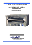
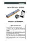
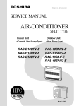
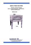
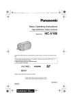
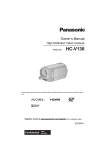
ELECTRIC TILTING BRATT PAN
PROUDLY AUSTRALIAN MADE
INSTALLATION PROCEDURE – USER MANUAL
SERVICE INSTRUCTION
MODELS TPE-75, TPE-100, TPE-150
TPE
ESTABLISHED 1911
The Cooking Equipment Professionals
www.goldsteineswood.com.au
TABLE OF CONTENTS
1.
INTRODUCTION
Page 3
2.
INSTALLATION
Page 4 & 5
3.
COMMISSIONING
Page 6
4.
OPERATING INSTRUCTIONS
Page 7 & 8
5.
TECHNICAL DATA
Page 9 & 10
6.
SERVICING
Page 11
7.
7.
WIRING DIAGRAM TPE-75
WIRING DIAGRAM TPE-100
Page 12
Page 13
8.
DRAWINGS
Page 14
9.
SPARE PARTS
Page 15
10.
WARRANTY
Page 16
11.
BRANCHES
Page 17
IM061B2/p2
1.
INTRODUCTION
Congratulations for purchasing your Goldstein commercial cooking appliance.
J. Goldstein & Co. is a wholly owned Australian company and has been
operating since 1911, building high quality products. The information in this
manual will assist your installer and ensure correct location and connection.
Thoroughly read the user instructions and the user maintenance sections, as
understanding your products, its operation, and its cleaning and service
requirements will provide you with long and satisfactory service. Failure to do
so could shorten the life of the product and decrease its efficiency. Please
ensure only authorised service technicians are called to any difficulties that
may arise.
INTRODUCTION
GOLDSTEIN ELECTRIC TILTING BRATT PAN
MODELS TPE-75 – TPE-100 – TPE-150
GOLDSTEIN TILTING BRATT PAN are designed to give long and satisfactory
service and incorporate the best possible materials and workmanship. Proper
installation, adjustment and preventative maintenance are vitally important if
efficiency and appearance are to be maintained.
A freestanding pan automatically controlled electric-operated Tilting Pan.
The Tilting pan is mounted on 4 legs 200mm long. The Tilting Pan is equipped
with a stainless steel back. Pan outer case and outer surround of stainless
steel, cooking pan of stainless steel, sand blast finish & incorporating element.
Read these instructions carefully as they contain important safety information
regarding the installation, usage and maintenance of this appliance.
IM061B2/p3
2. INSTALLATION
RECEIVING INSPECTION – PRE-INSTALLATION
Please follow these instructions carefully
•
•
•
•
•
•
Remove cartons from unit, check contents.
Lift off base and screw the adjustable legs into the base.
Set units in correct position.
Adjust feet till they are all touching the floor and using spirit level, level from front
to rear and left to right.
This operation is important as variation 25 mm to 76 mm in a room is found to be
common.
Check all loose items listing on the back of warranty card.
Have a licensed electrician connect your Tilting Pan to power, 3 phase Neutral &
Earth.
PRE-INSTALLATION OF TILTING PAN
• Check that there is sufficient clearance between doors and passageways to move
equipment into the cooking area.
• SPECIAL attention must be paid to fire hazards from combustible surfaces.
• Before first use, clean protective oil from bright parts and interior of pan with a
solution of washing soda or other grease dissolving material. Drain then rinse
thoroughly. (NOTE: It must be completely rinsed out, for even a small particle of
cleaner in the pan will ruin the cooking medium).
•
Ventilation
Adequate ventilation must be provided, preferably by a hood with vent and exhaust
fan.
INSTALLATION
NOTE:
IM061B2/p4
The appliance must be installed by an authorised person and in accordance
with the regulations of the local Energy Authority and any other authority
having jurisdiction. The appliance has been tested and preset before leaving
our factory, but small adjustments may be necessary to suit local conditions.
Correct operation of the appliance must be tested as part of the installation
procedure.
2. INSTALLATION Cont’d
Please follow these instructions carefully
1.
Set unit in desired position. If rear wall is of combustible material ensure there
is a minimum distance of 100mm between the back of the unit and the wall.
2.
Adjust feet till they are all touching the floor and using a spirit level from front
to rear and left to right. This operation is important as a floor variation of
25mm to 75mm in a floor is found to be common.
NOTE: The above levelling procedure is critical for the Tilting Pan to work
according to the manufacturers specifications.
3.
Have a Licensed electrician connect your Tilting Pan TPE-75 12 Kw, TPE-100
and TPE-150 18 Kw 3 phase +N.
4.
Also have your local plumber connect the water inlet.
CAUTION
NEVER ALLOW ELEMENTS TO OPERATE WITH TILTING PAN
EMPTY THIS DAMAGES THE PAN AND VOIDS WARRANTY
DO NOT TURN ON MAIN SWITCH UNLESS MAKING SURE THE
PAN BOTTOM IS COMPLETELY COVERED WITH COOKING
MEDIUM
NOTICE
PLEASE RETURN YOUR WARRANTY CARD
FAILURE TO DO SO WILL VOID WARRANTY
ON THE EQUIPMENT
IM061B2/p5
3. COMMISSIONING
COMMISSIONING APPLIANCE – DETAILS, TESTING, CHECKING
PRESSURE ETC.
COMMISSIONING CHECK LIST
1.
CHECK FOR DAMAGE AND MISSING PARTS.
2.
REMOVE ALL PLASTIC COATING FROM S/STEEL PANELS.
3.
MAKE SURE ALL PARTS ARE IN THEIR CORRECT POSITION E.G.
TRAYS BURNERS KNOBS.
4.
MAKE SURE ALL ELECTRIC AND GAS CONNECTIONS ARE CORRECT
AND TIGHT.
5.
LEVEL OFF UNIT LEFT TO RIGHT AND ALSO MAKE SURE THAT FRONT
IS JUST 3-4 MM LOWER TO ALLOW FOR FLUING.
6.
TURN ON GAS OR ELECTRICITY.
7.
ADJUST GAS PRESSURE WITH THREE-QUARTERS OF THE UNIT
RUNNING, ADJUST GAS PRESSURE.
NATURAL GAS
LPG
1.00 KPA
2.75 KPA
8.
TURN ON ONE AT A TIME TO MAKE SURE ALL IS WORKING E.G.
BURNER, RADIANT, GRIDDLE.
9.
SHOW CUSTOMER
A)
B)
C)
D)
10.
HOW TO WORK EQUIPMENT
HOW TO CLEAN
HOW TO PULL IT APART E.G. TRAYS, TRIVETS.
ALSO WHAT NOT TO DO, E.G. WATER WITH ELECTRICAL,
GREASE AND OIL IN CONTROLS.
CHECK TO MAKE SURE MANUALS AND WARRANTY CARDS ARE
THERE.
ALSO GO THROUGH MANUAL WITH CUSTOMER E.G. LIGHTING,
CLEANING.
NOTE:
WASH HOSES SHOULD NEVER BE USED ON THE APPLIANCE.
USE OF HOSES WILL VOID WARRANTY
IM061B2/p6
4. OPERATING INSTRUCTIONS
1
OPERATING BEFORE FIRST USE
Clean protective oil from bright parts and interior of pan with a solution of washing
soda or other grease dissolving material. Drain PAN then rinse thoroughly.
(Note: It must be completely rinsed out for even a small particle of cleaner in the pan
will ruin the cooking medium).
3.
CLEANING
Your Tilting Pan deserves the same care you give your cooking pots. It should
be kept clean and bright.
DAILY OPERATION
OPENING:
At opening time, always visually check the Tilting Pan Thermostat setting and main
Switch is off.
GENERAL USE OF THE TILTING PAN
a)
For consistent product quality, convenience and long-term savings, use a high
quality liquid frying compound.
b)
Temperature of frying compound. Although 180 degrees is the usual
temperature recommended for most cooking operations, Tilting Pan should be
carried out at lowest temperature, which will produce a high quality end
product while ensuring maximum life of the cooking compound. When the
Tilting Pan fryer is not in use, the temperature controller or operating
thermostat should be set lower than that used during cooking. Light loads, too,
may be cooked at lower temperatures. A good operator will experiment to
determine the best temperature and load conditions for the various foods to be
cooked.
WEEKLY
a)
Completely drain the Tilting Pan vessel into either the filter or steel contained.
Do not use a plastic bucket or glass container.
b)
Clean the vessel with a good grade of cleaner or hot water and a strong
detergent.
d)
Bring to a rolling boil, turn the heat down and let the mixture stand until
deposits and/or carbon spots can be rubbed off with the Teflon brush.
e)
Scrub the Pan walls, then drain the vessel and rinse in clear water.
f)
Refill with clear water and boil again.
g)
Drain, rinse and dry thoroughly
IM061B2/p7
3. OPERATING INSTRUCTIONS Cont’d
STAINLESS STEEL
All stainless steel body parts should be wiped regularly with hot, soapy water during
the day and with a liquid cleaner designed for this material at the end of each day.
DO NOT USE STEEL WOOL, ABRASIVE CLOTHS, CLEANSERS OR POWDERS!
If it is necessary to scrape stainless steel to remove encrusted materials, soak the
area with hot cloths to loosen the material, and then use a wood or nylon scraper.
DO NOT USE a metal knife, spatula, or any other metal tool to scrape stainless
Steel. Scratches are almost impossible to remove
IM061B2/p8
5.
TECHNICAL DATA
TPE-75-100 - 150
THERMOSTAT – LEFT HAND SIDE
The thermostat is readily removable from the front of the appliance after
removing the bulb of the power element from under the clamp between the
elements.
MAIN SWITCH
Removable from the front after unscrewing the front cover.
START UP PROCEDURE
1.
2.
3.
Switch on main switch.
Turn on thermostat and set the desired temperature.
If appliance is not fully operable within 30 minutes check that power
supply is correct at outlet of thermostat.
All repair work must be carried out by a licensed electrician.
WATER SPOUT
This spout is situated on the right top back front of the appliance and is a
Standard 12mm CP shower type and is a normal plumbing repair. All lines
leading to and from it are copper. The water outlet terminates in swivel neck
over the pan. This swivel neck is screwed into a flange, which is fastened to
the appliance by metal threaded nuts (As per Page 10). Inlet water connection
is on the left side 381 mm from the back approximately 114mm from the floor.
TILTING MECHANISM
Replacement or repair of faults can be achieved by bringing the pan to the
upper limits of tilt and also removing the front panel and right hand side panel.
TILTING MECHANISM (on manual lift only) (as on Page 10)
1.
2.
3.
4.
5.
6.
Crank Handle
Shaft Key
Stock
Fulcrum
Roller
Pan Pivots
IM061B2/p9
7.
8.
9.
10.
11.
Allen Screw
Worm Drive
Worm Drive bearings
Pivot
Roller Guide
5. TECHNICAL DATA Cont’d
IM061B2/p10
6. SERVICING
ACCESSING FRYERS FOR SERVICING
1.
Main Light on Switch NOT ON
(a) Check to see if working. May need New Switch.
(b) Check power.
2.
Some Sections not working
(a) Check 3 phase coming IN.
(b) Service person to check wiring.
3.
Water leaking from Top.
(a) Check washer in Top replace.
4.
Not cooking even.
(a) Check level of equipment.
(b) Check all elements are working.
(c) Check all 3 phase are coming in.
SERVICING
1.
Check power in 3∅ N,E.
2.
Check thermostat temperature.
3.
Motor is lifting..
4.
Check current rating amperage.
5.
Levelling is right.
6.
Water spout is not leaking.
IM061B2/p11
7. WIRING DIAGRAM
NNN N
N
N
AAA
PR06A05
IM061B2/p12
TOLERANCESON
DIMENSIONSUNLESS
OTHERWISESPECIFIED
WHOLEmm:±0.5
DECIMALS:±0.2
ANGULAR:±1°
DATE
CHECKED
Wing
SCALE
DRAWINGNo
7. WIRING DIAGRAM
N N N N
N
N
AAA
PR06A05
IM061B2/p13
TOLERANCESON
DIMENSIONSUNLESS
OTHERWISESPECIFIED
WHOLEmm:±0.5
DECIMALS:±0.2
ANGULAR:±1°
DATE
CHECKED
Wing
SCALE
DRAWINGNo
8. DRAWING
MODEL: TPE – 75, TPE – 100, TPE – 150
1
29
2
6
3
5
4
21
20
23
27
22
7
8
20
24
26
19
28
21
20
9
23
18
34
27
33
25
22
20
12
11
36
37
35
15
10
15
17
14
13
16
IM061B2/p14
30
31
32
9. SPARE PARTS
MODEL: TPE-75, TPE-100, TPE-150
ITEM No.
1.
2.
3.
4.
5.
6.
7.
8.
9.
10.
11.
12.
13.
14.
15.
16.
17.
18.
19.
CODE
TP-00M22
TP-00M18
TP-00M20
TP-00M21
TP-00M19
TP-00M17
TP-00A08
ECNP4S30
MTAW0001
TP-00M24
TP-00M11
TP-00M09
TP-00M13
TP-00M14
TP-00M10
TP-00M15
MHDPLTP1
MLEPLBF1
MLESSBFC
20.
21.
22.
23.
24.
25.
26.
27.
28.
29.
MCLIP002
TP-00M03
TP-00M05
TP-00M25
ECT45AK2
EEVB29B0
ESW00007
MKNPLTS6
MTH00320
EMO00017
30.
31.
32.
33.
ESW00025
ESW00020
ESWT0001
TP-00A10
34.
35.
36.
37.
MKNEP001
ECA00005
GNT00037
EMO00002
IM061B2/p15
DESCRIPTION
BRACKET – HANDLE HOLDER S/S ANGLE
TENSIONER – HEXAGON SPRING (TPI)
SPACER – BRASS 1 3/8” x 11/16” x 9/16”
SPRING – TPE
PIVOT PIN – HEX (TPE)
BRACKET – STAINLESS STEEL
WATER STAND PIPE ASSEMBLY
4 WAY PORCELAIN CONNECTOR
WATER TAP ASSEMBLY – CONTROL COCK
WINDING WHEEL AND HANDLE
SHAFT – DRIVE SHAFT HOUSING + BUSH
YOKE – STEEL (TILT)
BALL RACE – 51104 (TILT)
SPACER – BRASS 1 ¼” x ¾” x ¼”
LEADSCREW ASSEMBLY
WASHER – TILTING MECHANISM HANDLE
BLACK COLLAPSIBLE HANDLE ONLY
FEET – PLASTIC BULLET 2D
STAINLESS STEEL LEG WITH ADJ. PLASTIC
INSERT
CIRCLIP
HINGE – SINGLE PLATE HINGE
HINGE PIN – TILT PAN (70.5mm)
HINGE – 2 PLATE
CONTACTOR – 45A (ALL MODELS)
ELEMENT – 2KW (PEG/GPED/TPE)
SWITCH –MAIN. WITH SILICON BOOT
KNOB – (50°C~320°C)
THERMOSTAT – TP (50°C~320°C)
MOTOR – COMPLETE ELECTRONIC LIFTING
(SKF)
ROCKER SWITCH – BOOTED RUBBER
ROCKET SWITCH – LIFT
SWITCH – TOGGLE
SWITCH TOGGLE 3 WAY WITH RUBBER
BOOT
BEZEL FOR THERMOSTAT
7.5 MF CAPACITOR
BRASS NUT
MOTOR – COMPLETE ELECTRONIC LIFTING
MECH.85199
10. WARRANTY
Installation must be carried out according to local regulations by qualified trade
persons.
Isolating switch(es), shut-off valves etc must be within easy reach of the machine for
future service and maintenance requirements.
If in doubt call GOLDSTEIN/ESWOOD or their representative for further information.
No responsibility will be accepted for defects or damages by improper installation, for
changes to the product not authorised by GOLDSTEIN/ESWOOD or for operation
outside the technical specifications.
GOLDSTEIN/ESWOOD warrants their products to be free from defects in material
and workmanship under “normal use and service”. This does not include normal
wear and tear of parts. GOLDSTEIN/ESWOOD will repair or replace any parts, which
in GOLDSTEIN/ESWOOD’s sole judgement are defective in material or
workmanship, in accordance with the warranty offered.
This undertaking covers the provision of labour and parts for 12 months from the date
of delivery to the purchaser. This undertaking applies only to state capitals. Remote
areas are not covered by this commitment and special enquiries should be made.
(Note: Travel time not covered by warranty).
“To the maximum extent permitted by law, any liability on Goldstein/Eswood’s part or
on the part of its servants or agents for loss or damage of any kind whatsoever in
connection with the products, including liability for or in respect of any claim arising
out of contract, negligence or statute, shall not, in any event, exceed $100”
Labour under warranty is supplied free of charge during normal working hours,
Monday to Friday. Should warranty work be requested outside of our normal working
hours a labour charge will be applied equivalent to a normal hourly rate, without out of
hours penalty rates. (Refer to last page of this manual for your closest branch for
warranty repair services).
.
IM061B2/p16
11. J GOLDSTEIN & CO PTY LTD BRANCHES
For inquiries please call your nearest state branch:
Head Office
211-213 Woodpark Road
New South Wales 2564
Phone:
02 9604 7333
Fax:
02 9604 5420
Victoria
Unit 13
260-264 Wickham Road
Moorabbin
Victoria 3189
Phone:
03 9553 1488
Fax:
03 9553 0785
Queensland
Unit 3
49 Logan Road
Woolloongabba
Queensland 4102
Phone:
07 3891 1466
Fax:
07 3393 1333
South Australia
Suite 26
283-287 Sir Donald Bradman Drive
Brooklyn Park
South Australia 5032
Phone:
08 8238 3423
Fax:
08 8238 3400
Western Australia
10 Wittenberg Drive
Canning Vale
Western Australia 6155
Phone:
08 9456 0559
Fax:
08 9456 0554
IM061B2/p17