1
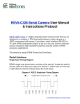
Select Room Rev. Delay Session Time Delay Session Time 1 2 3 5 4 6 TT40 8 7 10 9 00 00 00 00 00 00 00 00 00 00 11 12 13 14 15 16 17 18 19 20 1 2 3 Room # 4 5 6 Session Time 7 8 9 Start/ Stop Program 0 CANCEL TES/NO Read Meter Clear Meter 00 00 00 00 00 00 00 00 00 00 EXIT Bed Clean ENTER TT-40 Console TT-40 USER’S MANUAL Including Tan Time Room Unit Timers RU-DS Time Set Time Delay Session Start Stop Room Unit Digital Tanning Bed Timer Control Systems for Complete Salon Control TT-40 User’s Manual Main Console & Room Units Manufactured and Marketed by Tan Time, a Division of EPaD, Inc. (Electronic Programming and Design, Inc.) P.O. Box 81163 Seattle, WA 98108 © 2001 EPaD, Inc. All rights reserved --------------------------------------- TT-40 User’s Manual, July 2001 Electronic Programming and Design, Inc. (EPaD) and the Tan Time Division retains all ownership rights to all their products, and the contents of this manual. The source code for firmware and the electronic circuitry design are the confidential trade secrets of EPaD. You may not attempt to decipher, decompile, develop, or otherwise reverse engineer EPaD firmware or products. Information necessary to achieve interoperability is furnished upon request. The information in the manual is furnished for informational use only, is subject to change without notice, and should not be construed as commitment by EPaD. EPaD assumes no responsibility or liability for any errors or inaccuracies that may appear in this manual. No part of this manual may be reproduced, stored in a retrieval system, or transmitted, in any form or by any means, electronic, mechanical, recording, or otherwise, without the express written permission by EPaD. Existing artwork or images that you may desire to scan may be protected by copyright law. Be sure to obtain permission for use of existing artwork. Trademarks: These products carry the trademark of Tan Time and EPaD. All the trademarks of component parts used by Tan Time/EPaD in the manufacture of these products are the property of the respective owners. The Tan Time Logo and Systtem name and Logo are registered trademarks of EPaD. All other brand or product names are trademarks or registered trademarks of their respective companies or organizations. Written, designed, and illustrated by Electronic Programming and Design, Inc. P.O. Box 81163, Seattle, WA 98108, USA. Manufacturers Statement Limited Warranty, Disclaimer, Limitation of Liability EPaD warrants its products to be free of manufacturing defects, defects in materials and defects in workmanship for the lifetime of the products. Tan Time Products are warranted against normal wear and tear for a period of 12 months from the date of initial purchase. This warranty will not be honored if there has been any attempt to tamper with or remove the external seal, which is intended to preclude tampering with this product’s digital or other components. This warranty does not cover damage caused by misuse or abuse of this product or by acts of God or accidents or other misuse or improper installation or unauthorized repair or alteration or causes beyond the control of Tan Time. Also not covered by this warranty are claims other than by the original purchaser. Your sole remedy and our sole liability to you shall be to repair or replace particular products at our discretion if it does not meet the requirements of this warranty. If the product should become defective within the warranty period, upon receipt, Tan Time will repair or replace the product free of charge, at the option of Tan Time. Customer is responsible for all shipping charges. EPaD/Tan Time and its distributors shall under no circumstances be liable for any damages arising from the use of or the inability to use Tan Time products or from any loss of revenue or profit, business interruption, or other loss which may arise from the use of Tan Time products. THE WARRANTIES ABOVE ARE EXCLUSIVE AND IN LIEU OF ALL OTHER WARRANTIES, WHETHER EXPRESS OR IMPLIED, INCLUDING THE IMPLIED WARRANTIES OF MERCHANTABILITY AND FITNESS FOR A PARTICULAR PURPOSE. Table of Contents INTRODUCTION . . . . . . . . . . . . . . . . . . . . . . . . . . . . . . . . . . . . . . . . . . . . . . . . . . . . . . . . . . . 1 The Company . . . . . . . . . . . . . . . . . . . . . . . . . . . . . . . . . . . . . . . . . . . . . . . . . . . . . . . . . . . . . . . . 1 The Products . . . . . . . . . . . . . . . . . . . . . . . . . . . . . . . . . . . . . . . . . . . . . . . . . . . . . . . . . . . . . . . . 1 This Manual . . . . . . . . . . . . . . . . . . . . . . . . . . . . . . . . . . . . . . . . . . . . . . . . . . . . . . . . . . . . . . . . . 1 SUPPORT . . . . . . . . . . . . . . . . . . . . . . . . . . . . . . . . . . . . . . . . . . . . . . . . . . . . . . . . . . . . . . . . . . 2 Tan Time Dedication . . . . . . . . . . . . . . . . . . . . . . . . . . . . . . . . . . . . . . . . . . . . . . . . . . . . . . . . . 2 User’s Manual Help Sections . . . . . . . . . . . . . . . . . . . . . . . . . . . . . . . . . . . . . . . . . . . . . . . . 2 Customer Support . . . . . . . . . . . . . . . . . . . . . . . . . . . . . . . . . . . . . . . . . . . . . . . . . . . . . . . . . . . . . 2 Specifications . . . . . . . . . . . . . . . . . . . . . . . . . . . . . . . . . . . . . . . . . . . . . . . . . . . . . . . . . . . . . . . 3 TT-40 Systtem Main Console and Expansion Console: . . . . . . . . . . . . . . . . . . . . . . . . Room Units: . . . . . . . . . . . . . . . . . . . . . . . . . . . . . . . . . . . . . . . . . . . . . . . . . . . . . . . . . . . . . . . . . Communications Cabling: . . . . . . . . . . . . . . . . . . . . . . . . . . . . . . . . . . . . . . . . . . . . . . . . . . . . TT-40 Systtem Console to Room Units (Daisy Chain): . . . . . . . . . . . . . . . . . . . . . . . . . . . . . TT-40 Systtem Console to PC: . . . . . . . . . . . . . . . . . . . . . . . . . . . . . . . . . . . . . . . . . . . . . . . . . . . 3 3 3 3 3 SYSTTEM COMPONENTS . . . . . . . . . . . . . . . . . . . . . . . . . . . . . . . . . . . . . . . . . . . . . . . . 4 Systtem TT-40 Console . . . . . . . . . . . . . . . . . . . . . . . . . . . . . . . . . . . . . . . . . . . . . . . . . . . . . . 4 Systtem TT-40 Console . . . . . . . . . . . . . . . . . . . . . . . . . . . . . . . . . . . . . . . . . . . . . . . . . . . . 5 Console Data Entry and Display Components . . . . . . . . . . . . . . . . . . . . . . . . . . . . . . . . . LCD Status Display . . . . . . . . . . . . . . . . . . . . . . . . . . . . . . . . . . . . . . . . . . . . . . . . . . . . . . . . . . . . Data Entry Keypad . . . . . . . . . . . . . . . . . . . . . . . . . . . . . . . . . . . . . . . . . . . . . . . . . . . . . . . . . . . . Power Input, and Power Switch . . . . . . . . . . . . . . . . . . . . . . . . . . . . . . . . . . . . . . . . . . . . . . . . . Room Unit Connection Ports . . . . . . . . . . . . . . . . . . . . . . . . . . . . . . . . . . . . . . . . . . . . . . . . . . . . Console Mounting Brackets . . . . . . . . . . . . . . . . . . . . . . . . . . . . . . . . . . . . . . . . . . . . . . . . . . Room Unit Control and Display Components . . . . . . . . . . . . . . . . . . . . . . . . . . . . . . . . . LED Status Lights . . . . . . . . . . . . . . . . . . . . . . . . . . . . . . . . . . . . . . . . . . . . . . . . . . . . . . . . . . . . . Set Time Input Button . . . . . . . . . . . . . . . . . . . . . . . . . . . . . . . . . . . . . . . . . . . . . . . . . . . . . . . . . Connection Ports . . . . . . . . . . . . . . . . . . . . . . . . . . . . . . . . . . . . . . . . . . . . . . . . . . . . . . . . . . . . . . End of Line Terminator . . . . . . . . . . . . . . . . . . . . . . . . . . . . . . . . . . . . . . . . . . . . . . . . . . . . . . . . Bed Switching Leg Connector . . . . . . . . . . . . . . . . . . . . . . . . . . . . . . . . . . . . . . . . . . . . . . . . . . . OPERATION . . . . . . . . . . . . . . . . . . . . . . . . . . . . . . . . . . . . . . . . . . . . . . . . . . . . . . . . . . . . . Computer Operation . . . . . . . . . . . . . . . . . . . . . . . . . . . . . . . . . . . . . . . . . . . . . . . . . . . . . . . Manual Operation of the TT-40 Systtem Console . . . . . . . . . . . . . . . . . . . . . . . . . . . . .Operator Interfaces . . . . . . . . . . . . . . . . . . . . . . . . . . . . . . . . . . . . . . . . . . . . . . . . . . . . . . . . . Steps Before Systtem Operation Can Occur. . . . . . . . . . . . . . . . . . . . . . . . . . . . . . . . . . . . . Setting Time and Running a Session from the Console . . . . . . . . . . . . . . . . . . . . . . Canceling a Session . . . . . . . . . . . . . . . . . . . . . . . . . . . . . . . . . . . . . . . . . . . . . . . . . . . . . . . 5 5 5 5 5 6 8 9 9 9 9 9 10 10 10 10 11 12 13 Table of Contents From the Console . . . . . . . . . . . . . . . . . . . . . . . . . . . . . . . . . . . . . . . . . . . . . . . . . . . . . . . . . . . . From the Room Unit . . . . . . . . . . . . . . . . . . . . . . . . . . . . . . . . . . . . . . . . . . . . . . . . . . . . . . . . . Pausing a Session . . . . . . . . . . . . . . . . . . . . . . . . . . . . . . . . . . . . . . . . . . . . . . . . . . . . . . . . . Clearing the “Bed Clean” Indicator . . . . . . . . . . . . . . . . . . . . . . . . . . . . . . . . . . . . . . . . . . . . Displaying and Editing the Meter Data on the Console . . . . . . . . . . . . . . . . . . . . . . Meter Data . . . . . . . . . . . . . . . . . . . . . . . . . . . . . . . . . . . . . . . . . . . . . . . . . . . . . . . . . . . . . . . . . Bulb Life Meter Data . . . . . . . . . . . . . . . . . . . . . . . . . . . . . . . . . . . . . . . . . . . . . . . . . . . . . . . . Procedure - Displaying Meter Data . . . . . . . . . . . . . . . . . . . . . . . . . . . . . . . . . . . . . . . . . . . . Setting the Bulb Life Meter . . . . . . . . . . . . . . . . . . . . . . . . . . . . . . . . . . . . . . . . . . . . . . . . . . . Bulb Life Meter Alert . . . . . . . . . . . . . . . . . . . . . . . . . . . . . . . . . . . . . . . . . . . . . . . . . . . . . . . . Clearing the Bulb Life Meter . . . . . . . . . . . . . . . . . . . . . . . . . . . . . . . . . . . . . . . . . . . . . . . . . . Clearing the Resetable Hour & Session Meter at the Console . . . . . . . . . . . . . . . . . . . . . . 13 13 13 13 14 14 14 14 15 15 15 15 Operation of the Room Units . . . . . . . . . . . . . . . . . . . . . . . . . . . . . . . . . . . . . . . . . . . . . 16 16 16 16 16 Operating Room Units from the TT-40 Console . . . . . . . . . . . . . . . . . . . . . . . . . . . . . Operating Room Units in Stand Alone Mode . . . . . . . . . . . . . . . . . . . . . . . . . . . . . . . . Remote Start/Stop Push Button (Optional Equipment) . . . . . . . . . . . . . . . . . . . . . . . . . . . Cool Down Function . . . . . . . . . . . . . . . . . . . . . . . . . . . . . . . . . . . . . . . . . . . . . . . . . . . . . . . . . SETUP . . . . . . . . . . . . . . . . . . . . . . . . . . . . . . . . . . . . . . . . . . . . . . . . . . . . . . . . . . . . . . . . . . . Setting Room Parameters in the TT-40 Systtem Console . . . . . . . . . . . . . . . . . . . . Entering the Room Setup Menu on the Console . . . . . . . . . . . . . . . . . . . . . . . . . . . . . . . . . Six Room Setup Parameters . . . . . . . . . . . . . . . . . . . . . . . . . . . . . . . . . . . . . . . . . . . . . . . . . . The Console’s six (6) Room Setup Parameters: . . . . . . . . . . . . . . . . . . . . . . . . . . . . . . . . . . Setting Up the Console and Entering Session Preferences . . . . . . . . . . . . . . . . . . Accessing the Global Procedures Menu . . . . . . . . . . . . . . . . . . . . . . . . . . . . . . . . . . . . Description of Global Procedure Menu . . . . . . . . . . . . . . . . . . . . . . . . . . . . . . . . . . . . . . . . . Instructions for each of the 8 Global Procedures . . . . . . . . . . . . . . . . . . . . . . . . . . . . . . . . . 1 - Setup Room Numbers: . . . . . . . . . . . . . . . . . . . . . . . . . . . . . . . . . . . . . . . . . . . . . . . . . . . . 2 - System Status Test . . . . . . . . . . . . . . . . . . . . . . . . . . . . . . . . . . . . . . . . . . . . . . . . . . . . . . . Five Possible Outcomes: . . . . . . . . . . . . . . . . . . . . . . . . . . . . . . . . . . . . . . . . . . . . . . . . . . . . . 3 - New Manager’s Code . . . . . . . . . . . . . . . . . . . . . . . . . . . . . . . . . . . . . . . . . . . . . . . . . . . . . 4 - Factory Settings . . . . . . . . . . . . . . . . . . . . . . . . . . . . . . . . . . . . . . . . . . . . . . . . . . . . . . . . . . 5 - Purge All Meters . . . . . . . . . . . . . . . . . . . . . . . . . . . . . . . . . . . . . . . . . . . . . . . . . . . . . . . . . . 6 - Purge All Net ID’s . . . . . . . . . . . . . . . . . . . . . . . . . . . . . . . . . . . . . . . . . . . . . . . . . . . . . . . . 7 - Save Meter Data . . . . . . . . . . . . . . . . . . . . . . . . . . . . . . . . . . . . . . . . . . . . . . . . . . . . . . . . . . 8 - Restore Meter Data . . . . . . . . . . . . . . . . . . . . . . . . . . . . . . . . . . . . . . . . . . . . . . . . . . . . . . . Setting Up the Room Units . . . . . . . . . . . . . . . . . . . . . . . . . . . . . . . . . . . . . . . . . . . . . . . . . General Setup Information . . . . . . . . . . . . . . . . . . . . . . . . . . . . . . . . . . . . . . . . . . . . . . . . . . . 17 17 17 17 18 19 19 19 20 20 23 23 23 23 24 24 24 24 25 25 Table of Contents Setting up the Room Units for Stand-alone Mode ............................... 25 INSTALLATION . . . . . . . . . . . . . . . . . . . . . . . . . . . . . . . . . . . . . . . . . . . . . . . . . . . . . . . . . . 26 26 26 26 26 27 27 28 28 28 29 Installing the TT-40 Main Console . . . . . . . . . . . . . . . . . . . . . . . . . . . . . . . . . . . . . . . . . . Mounting Brackets . . . . . . . . . . . . . . . . . . . . . . . . . . . . . . . . . . . . . . . . . . . . . . . . . . . . . . . . . . Installing the Expansion Unit (an Extra Console) . . . . . . . . . . . . . . . . . . . . . . . . . . . Expansion Console Installation Procedure: . . . . . . . . . . . . . . . . . . . . . . . . . . . . . . . . . . . . . . Installing the Room Units . . . . . . . . . . . . . . . . . . . . . . . . . . . . . . . . . . . . . . . . . . . . . . . . . . Room Unit Installation Procedure: . . . . . . . . . . . . . . . . . . . . . . . . . . . . . . . . . . . . . . . . . . . . . Communication Network Wiring . . . . . . . . . . . . . . . . . . . . . . . . . . . . . . . . . . . . . . . . . . . . TT-40 Console to Room Unit Cable: . . . . . . . . . . . . . . . . . . . . . . . . . . . . . . . . . . . . . . . . . . . Room Unit to Room Unit Cable: . . . . . . . . . . . . . . . . . . . . . . . . . . . . . . . . . . . . . . . . . . . . . . . Communications Cabling and Connection Diagram . . . . . . . . . . . . . . . . . . . . . . . . . . . . . . TROUBLESHOOTING . . . . . . . . . . . . . . . . . . . . . . . . . . . . . . . . . . . . . . . . . . . . . . . . . . . Test Procedure - Test Number of Room Units Per Daisy Chain: . . . . . . . . . . . . . . Test Procedure - Timer System Status Test . . . . . . . . . . . . . . . . . . . . . . . . . . . . . . . . . Interpreting Timer System Status Test Results . . . . . . . . . . . . . . . . . . . . . . . . . . . . . . . . . . Helpful Hints . . . . . . . . . . . . . . . . . . . . . . . . . . . . . . . . . . . . . . . . . . . . . . . . . . . . . . . . . . . . . . . 30 30 30 31 31 Introduction and Support INTRODUCTION The Company Since 1994, Tan Time, a Division of Electronic Programming and Design, Inc. Has been developing and manufacturing enhanced digital timer systems for the indoor tanning industry. Tan Time continually accesses the most innovative design technology available incorporating state of the art technology in all it’s Products. As an industry leader, Tan Time updates and adds new products to it’s growing line of digital timers and strives for complete customer satisfaction by providing a quality product and unsurpassed customer support. The Products The Tan Time TT-40 Systtem timer has been developed to provide the tanning salon operator with the means to control their individual tanning beds and monitor the status of all tanning units at a glance. The available units include the TT-40 Console, Expansion Console, individual Room Units, peripheral devices, and all required cabling for timer intercommunications. In addition to the TT-40 and other products, Tan Time offers custom timers for OEM Tanning Bed Manufacturers. Visit: www.tantime.com for more product information. This Manual There are 5 general use-specific sections in this manual: Systtem Components, Operation, Setup, Installation, and Troubleshooting. In addition there is support related information, and product specifications. It is recommended that your read this manual before unpacking, installing or operating your new Tan Time Systtem Timers. Important information is covered in this manual that will ease installation and ensure trouble-free operation. Failure to follow setup & operation directions could result in damages not covered by the warranty. 1 Introduction and Support SUPPORT Tan Time Dedication Tan Time is dedicated to ensuring that you receive the best customer support and technical assistance possible. To ensure that you receive the most efficient help possible, please be ready to produce model numbers of the Tan Time equipment in concern and product part numbers. For repairs and returns please be prepared to produce date of purchase, name of original purchaser, and PO Number. An RMA is required for all returns including both repairs and return-for-credit equipment returns. User’s Manual Help Sections Follow the procedures described in the Operation, Setup, and Installation sections of this manual. Following the procedures and paying close attention to how the timer Systtem is supposed to work will ensure trouble free installation and use. Also refer to the Troubleshooting section for diagnosing problems. Customer Support Telephone: Call Tan Time / EPaD at 206-767-7262 Pacific Time M-F 9 AM to 5 PM, PST Email: Tan Time Technical Support: [email protected] Returns and Repairs: NOTE: A Return Merchandise Authorization (RMA) number must be obtained from Tan Time prior to shipping repair or return equipment. The customer is responsible for all shipping costs. To be issued an RMA Number Call Tan Time at 206-767-7262, M-F, 9 AM to 5 PM, PST. Shipping / Mailing Address: You will receive the shipping address when obtaining your RMA number. Sales - Ordering Additional Equipment: Telephone: Call Tan Time at 206-767-7262, Pacific Time, M - F, 9A - 5P. Email: [email protected] Visit Web Site: www.tantime.com 2 Specifications SPECIFICATIONS TT-40 Systtem Main Console and Expansion Console: Size, Weight-------------------------------------------------Case Material -----------------------------------------------Temperature Range --------------------------------------Humidity -----------------------------------------------------Input Power: Voltage --------------------------------------------------Current Draw -------------------------------------------Timer Intercommunications: Console to Room Unit -------------------------------Console to Expansion Console -------------------Communication Interface: To Room Units ----------------------------------------To Expansion Unit -----------------------------------To Computer ------------------------------------------Maximum number or Room Units --------------------Maximum number of Room Unit Drops -------------Maximum Distance of Communication Cabling: Console to Room Unit ------------------------------Room Unit to Room Unit ---------------------------Daisy Chain --------------------------------------------Mounting Bracket ------------------------------------------- 12-1/2” x 6-1/2” x 1-5/8”., 2.0 lb. Painted Aluminum, Plastic 0ºC to + 60ºC 0% to 95% (non-condensing) 12 VDC 1500 mA Maximum RS-485 Direct Connection RJ-11, 6-pin, (4 ports) DB-37 Female Console, Male Exp. Console DB-9 Female 40 Room Units 10 Room Units per line, 4 lines maximum 100 ft. 50 ft. 600 ft. Painted Aluminum Room Units: Size, Weight-------------------------------------------------Case Material -----------------------------------------------Temperature Range --------------------------------------Humidity -----------------------------------------------------Input Voltage -----------------------------------------------Timer Intercommunications ----------------------------Communication Interface -------------------------------Cool Down Relay Interface -----------------------------Maximum number of Room Unit Drops -------------Maximum Distance of Communication Cabling ---Switching Leg Relay Limits ------------------------------ 4-1/2” x 4-5/8” x 1-1/4”, 0.5 lb. Plastic 0ºC to + 60ºC 0% to 95% (non-condensing) 12 VDC RS-485 RJ-45, 8-pin, (2 ports) 2 Position Terminal Block, 18-26 AWG 10 per Port of Console See Console Specifications 2 Amps, 220 VAC Communications Cabling: TT-40 Systtem Console to Room Units (Daisy Chain): Communications Type -----------------------------Maximum Cable Length ---------------------------Cable Type -------------------------------------------Connector Types ------------------------------------- RS-485 100 ft. 8 conductor, CAT 5 RJ-11, 6-pin (Console), RJ-45 (Room Units) TT-40 Systtem Console to PC: Communications Type -----------------------------Maximum Cable Length ---------------------------Cable Type -------------------------------------------Connector Types ------------------------------------- RS-232 50 ft. 9 conductor, straight through pin out. DB-9 Male to DB-9 Female 3 Systtem Components SYSTTEM COMPONENTS Systtem TT-40 Console The Console is the main control and display center for the timer Systtem. The Console provides power and control for the Room Units. Room Unit status is displayed on the individual LED Displays on the Console. Timer Systtem status, setup information, and setup instructions are displayed on the four-line LCD display on the front of the Console. Select Room Rev. Delay Session Time Delay Session Time 1 2 3 4 5 6 7 TT40 8 9 1 2 3 Room # 4 5 6 Session Time 7 8 9 Program 0 CANCEL EXIT Bed Clean TES/NO Read Meter Clear Meter ENTER 10 00 00 00 00 00 00 00 00 00 00 11 12 13 14 15 16 17 18 19 20 00 00 00 00 00 00 00 00 00 00 Start/ Stop TT-40 Systtem Console All data, setup information, and session control is acquired using the keypad on the right of the console. The TT-40 Console supports connection to and control of up to 20 Room Units. The Console Expansion Unit adds control capability for an additional 20 Room Units. Systtem TT-40 Expansion Console The Console Expansion Unit is functionally identical to the TT-40 Console. It adds the capability to control and monitor an additional 20 Room Units. The Expansion Console is not a required product unless you have 21 or more tanning beds in your salon. It is installed directly underneath the Main Console using the supplied brackets and makes direct connection to the Main Console via the expansion port. A separate power supply is used to power the Expansion Console. Systtem Room Unit The Room Units provide the local control and display for individual tanning units. The Room Unit is a single, self-contained timer that can operate either as a stand-alone timer or with a TT-40 or other Tan Time Systtem Console. RU-DS Time Set Time Delay Session Start Stop Power for the Room Unit is supplied either by the Console-Room Unit Systtem Room Unit Communications Cable or by an optional individual power supply. The Room Unit has one dual-digit LED Display, two status lights, two front panel buttons, and the option for a remote start/stop switch. 4 Systtem Components Systtem TT-40 Console TT-40 Systtem Console Communications Ports to Room Units (qty.4) Comm Port to PC LCD Status Display Select Room Rev. Delay Session Time Delay Session Time On/Off Switch & Power Input 1 2 3 4 5 6 7 TT40 8 9 10 0 0 0 0 0 0 0 0 0 0 0 0 0 0 0 0 0 0 0 0 11 12 13 14 15 16 17 18 19 20 1 2 3 Room # 4 5 6 Session Time 9 Start/ Stop 7 8 Program 0 TES/NO Read Meter 0 0 0 0 0 0 0 0 0 0 0 0 0 0 0 0 0 0 0 0 Room LED Display Data Entry Keypad CANCEL EXIT Bed Clean Clear Meter ENTER To Expansion Console Systtem Main Console Diagram Console Data Entry and Display Components Refer to the above diagram as reference through the following Console feature descriptions. LCD Status Display The LCD display shows the current status of the Console. All setup guides, meter information, and instruction prompts are shown on this display. Data Entry Keypad The Data Entry Keypad is used to enter all the data for the timer system. Power Input, and Power Switch 12 VDC Power is provided for the Console via the power plug on the left side of the Console. An On/Off switch located on the power input housing controls power to the Console. A Wall Mount Power Supply is provided with the TT-40 Console and the Expansion Console. Note: Room Units receive power from the Console via the Console-Room Unit cabling. Unless the Room Units are powered separately, disabling power to the Console also disables the Room Units. Room Unit Connection Ports There are 4 Room Unit communications ports on the top edge of the TT-40 Console. These ports are RJ-11, 6-pin, “Telephone Type” connector ports. Communications and power for the Room Units are made over the Console-Room Unit Cabling. Each of the Console’s four ports support a daisy chain connection to a maximum of 10 Room Units per chain. A total of 40 Room Units can be accessed using the Main and Expansion Console. 5 Systtem Components Console Data Entry and Display Components (continued) Console Room LED Displays The Room Unit Displays show the status of the remote Room Units. The Main Console has 20 Room LED Displays. The Expansion Console adds 20 more Room LED Displays. The Console Room LED Displays have Six Display Modes: 1. Idle When the Room Unit is Idle, i.e., ready to use, the display will show steady [ 00 ]. 2. Delay When a session has been started and a delay time programmed, the display will show the time remaining before starting the session. When a delay is in effect the Room Unit’s Delay Light will also be on. 3. Session Session time will show on the LED when a session is ready to start. When a session has started the Room Unit’s Session Light will also be on. 4. Clean Bed The display will flash “00” after a session has ended if the clean bed option has been turned on. When the bed has been cleaned, the display will show solid zeros [ 00 ]. 5. Lost Communications If a Room Unit has been assigned within the Console but the console can not find the Room Unit the Console Room LED Displays will show flashing “88”. 6. Test Display Readout If a Room Unit has been assigned within the Console the Room LED Display will show the room number for the Room Units it can find on the network and flashing “88” for those Room Units not found but previously setup. Console Mounting Brackets Wall Mount and Desk Mount mounting brackets are available for the TT-40 Console: Ÿ Wall Mount Bracket: allows the console and the expansion unit to be flush-mounted on any vertical surface. Ÿ Desk Mount Bracket: allows the console to be displayed at a comfortable 70º angle on any flat surface. 6 Systtem Components Systtem Room Unit On Back: LED Time Display Comm Ports Bed Relay Terminal Block RU-DS Input Buttons Time Set Time Delay Session LED Status Displays Start Stop Remote Start/Stop Connection Accessories Connection Room Unit Room Unit Diagram The Room Units provide the local control and display for individual tanning units. The Room Unit is a single, self-contained timer that can operate either as a stand-alone timer or with a TT-40 Console. Power for the Room Unit is supplied either by the Console-Room Unit communications cable or by an optional individual power supply. The Room Unit has one dual-digit LED Display, two status lights, two front panel buttons, and the option for a remote start/stop switch. 7 Systtem Components Room Unit Control and Display Components LED Time Display Room Unit LED Time Display indicates Four Modes of Operation: 1. Idle When the Room Unit is idle, i.e., ready to use, the display will show [ 00 ]. 2. Delay When a session has started and a delay time has been programmed from the Console, the display will show the delay time remaining before the session begins. The delay light will be on when a delay has been programmed. 3. Session Session time in minutes will show on the LED display when a session is ready to start. The session light will be on when a session has started. 4. Clean Bed The display will flash “00” after a session if the clean-bed option has been turned on. The display will show solid [ 00 ] when the bed has been cleaned. 8 Systtem Components Systtem Room Unit and Room Unit Control and Display Components (continued) LED Status Lights Delay Session The Room Unit Status Lights indicate either a delay mode or session mode of operation. Set Time Input Button Set Time Start Stop This control button is used to set Room Unit session time in Stand-alone Mode. (NOTE: the Room Unit Set Time button has no affect when the Console is in control.) Start/Stop This button is used to start or stop the session in all modes of operation. Connection Ports RJ-45 Comm. Ports There are two RJ-45, 8-pin, ports on the back side of the Room Unit. The cables that plug into the ports provide the Room Units both communications and power from the TT-40 Console. These are “pass through” ports. They are electrically identical. Either port can be used for the cable coming from the Console or to/from another Room Unit. The in-out cable arrangement is referred to as a Daisy Chain configuration. End of Line Terminator If a given Room Unit is the last in the daisy chain an End of Line Terminator should be connected to the open RJ-45 Communications port. RJ-45 Jack to one of the two Room Unit ports End of Line Terminator Red LED On when connected Bed Switching Leg Connector The Switching Leg Connector provides AC control of the tanning units’ contactor and is required to allow control of the tanning bed. The two position terminal block input is for connection of AC voltage only, not DC. Maximum Limit: 2 Amps, 220 VAC. NOTE: The connection is not for DC voltage. Control of the tanning bed is not possible using a DC voltage connection to the Bed Switching Leg Connector. Contact Tan Time for the optional relay if a DC voltage connection is needed. 9 Operation OPERATION Computer Operation A PC and third-party tanning salon software can be used to control the Tan Time Systtem. Manual operation of the Tan Time Systtem (TT-40 Console and Room Units) is not done if a third party Tanning Salon Software Program is used. PC/software controls replace manual Console keypad control. It is important to note that operation of the TT-40 Console and Room Units does not require the use of software. However, third-party Tanning Salon Control Software can be used. Tan Time does not offer the software. Acquire it from another source. Refer to your tanning salon software operations manual for the proper setup procedure to be used for the Tan Time Systtem. To set the Room Units for computer-only operation do so from the Console. See the SETUP Section Page 20, #5, “Setting up the Room Units from the TT-40 Systtem Console. Manual Operation of the TT-40 Systtem Console The Tan Time Timer Systtem is designed to control all the tanning beds in your tanning salon. The Console is the control center for the Tan Time Systtem. Console LCD Display Room LED Display Select Room Rev. Delay Session Delay Session 1 Time Delay Session Time 1 2 3 4 5 6 7 TT40 8 9 10 00 00 00 00 00 00 00 00 00 00 11 12 13 14 15 16 17 18 19 20 1 2 3 Room # 4 5 6 Session Time 7 8 9 Program 0 CANCEL EXIT Bed Clean TES/NO Read Meter Clear Meter ENTER 00 00 00 00 00 00 00 00 00 00 Time TT-40 Systtem Console Start/ Stop 1 2 3 4 5 6 Session Time 7 8 9 Start/ Stop Program 0 CANCEL EXIT Bed Clean YES/NO Read Meter Clear Meter ENTER .Operator Interfaces Consoles Data Entry Keypad.→ All setup entries, user preferences, and operational commands are made using the keypad buttons. Room # Data Entry Keypad The LCD Display It shows instruction prompts, and user information. Room LED Displays There are 20 Room LED Displays on the Console. They provide Room Units status. 10 Operation Manual Operation of the TT-40 Systtem Console (continued) Below are the Initial Console LCD Display Screens you will see following power up. TT40-Version 1.7 TT40-Version 1.7 After installing and applying power to the TT-40 Console you will initially see this LCD display screen. After roughly 2 seconds the LCD shows this screen while the Console goes through it’s Room LED Display self-test. One Moment Please ... Select Room# Key After the self-test the Console is ready for data entry and use. This is the opening LCD screen of the Console from which all setup and Systtem operations follow. Steps Before Systtem Operation Can Occur. The Tan Time Systtem requires user setup prior to being able to you control your salon. Before Operation of the Tan Time Systtem the following steps are recommended: 1. Install the Room Units at the individual tanning beds. 2. Setup each Room Unit for Stand-alone Operation. 3. Test the Room Units ability to control the tanning beds each is installed for. 4. Install the TT-40 Systtem Console. 5. Install the Cabling between the Console and Closest Room Unit. 6. Install the Cabling between Room Units being sure to install the End-of-Line Terminator on the last Room Unit in the daisy chain. 7. Setup Room Unit Options within the TT-40 Console. 8. Enter Global Setup (Global Procedures) from which you will setup the room numbers within the Console as well as set up the Room Units for Console control and Systtem integration. Order of Manual reference sections new Tan Time customers will follow: INSTALLATION - For initial installation of the Tan Time System follow the instructions in the this section of the manual. SETUP - After initial installation refer to this section of this manual and complete the instructions therein. OPERATION - This OPERATION Section is intended to be used as a reference for daily-use or by new users who need guidance for operating. 11 Operation Manual Operation of the TT-40 Systtem Console (continued) Setting Time and Running a Session from the Console Follow the steps (a.) through (e.) below to set time and start a session: Select Room# Key Start from this LCD screen on the Console. a. Press the Room # key. --ENTER ROOM NUMBERRoom Number = 0 See this LCD screen. b. Enter the Room Number desired using the keypad. c. --SESSION TIME # 1 - Time = 0 Press the Session Time key. See this LCD screen. d. Enter desired session time using the keypad. e. Press the Start / Stop button to Start the session and see notes below. NOTES: § The session time or delay, if set, will now be displayed on the Console and Room Unit. § If Manual Start is set to Yes, the bed will be off until it is started from the room. § If Manual Start is set to No, the session will start immediately after pressing the Start/Stop button on the Console. § The Delay Light on the Room Unit and Console will be illuminated if the timer was setup with a delay time, and both the Console and the Room Unit will display the delay time remaining until the session begins. § When the Delay Time has counted down or if no delay time was setup, the Session Light on the Room Unit and Console will illuminate indicating that a session is in progress. 12 Operation Manual Operation of the TT-40 Systtem Console (continued) Canceling a Session From the Console A Session can be canceled at any time. To do so follow the steps below: a. Press the Room # key. b. Enter the room number desired using the keypad. c. Press the Start/Stop key. The Session will be canceled and the Console will be set to zero. From the Room Unit To cancel a session from the Room Unit follow the steps below: a. Press and hold the Start/Stop button on the Room Unit for four seconds. b. The Room Unit Status Session LED will go off and the LED Time Display will show 00. Pausing a Session A session may be paused only at the Room Unit. To pause a session follow the steps below: a. press the Start/Stop button on the Room Unit (while the Session is in progress). This action turns off the tanning unit but the session continues to count down. b. To restart the session press the Start/Stop button again. This will turn the tanning unit back on Clearing the “Bed Clean” Indicator A Bed Clean condition is indicated by flashing zeros, “00” on the Console LED Display. To clear the “Bed Clean” Indicator at the TT-40 Console follow these steps: a. Press the Room # key on the Data Entry Keypad. b. Press the Bed Clean key. The room LED display will show a double zeros when cleared. ( 00 ). To clear the “Bed Clean” Indicator at the Room Unit follow these steps: a. Press the Start/Stop button on the Room Unit. b. Or, if installed, press the optional remote Start/Stop button in the room. The Room Unit will now show double zeros. ( 00 ). . 13 Operation Manual Operation of the TT-40 Systtem Console (continued) Displaying and Editing the Meter Data on the Console There are two types of Data; Meter Data and Bulb Life Meter Data. Meter Data The TT-40 automatically tracks and stores the number of tanning sessions and the combined session time of the individual Room Units. This information is stored independently by the Console and can serve as a valuable cross check of salon use for billing purposes. Bulb Life Meter Data The TT-40 Console automatically tracks the remaining life in the tanning bed bulb. The Bulb Life Meter feature is set when a new bulb is installed or when the tanning bed and it’s bulb are brand new. Procedure - Displaying Meter Data To display the Room Unit Meter Data and Bulb Life Meter Data on the Console: Select Room# Key Start from this LCD screen. a. Press the Room # key on the Data Entry Keypad. --ENTER ROOM NUMBERRoom Number = 0 See this screen. b. Enter the room number for which meter data is desired using the keypad. c. -- METER DATA # 1 -# Sessions Hours : Min Prm = 6 * 1 : 36 Tmp = 5 * 0 : 24 Press the Read Meter button. See this screen. Prm = Permanent. Meter Data stored in permanent Memory. Tmp = Temporary. Meter data that can be reset. Continue for Bulb Life Meter Data... -- BULB DATA # 1 -Bulb Life =0 Hours Used =1 Hours Remaining = 70 d. Press Read Meter again and see this screen. e. To Exit the Meter Display Mode Press ENTER or CANCEL on the Console keypad. 14 Operation Displaying and Editing the Meter Data on the Console (continued) Setting the Bulb Life Meter Go to the SETUP section and follow instructions for “Setting up the Room Units from the TT-40 Systtem Console” Bulb Life Meter Alert When the Bulb Life Meter has run down to zero the LED indicator for that specific room will display alternating flashing eights, “8L”, “8R”, ... Clearing the Bulb Life Meter To Clear the Bulb Life Meter alert follow the steps below: a. Press the Room # key on the Console keypad. b. Enter the room number to be cleared. c. Press the Clear Meter Key. The Bulb Life Meter is now at zero. d. To restart the Bulb Life Meter countdown you must reset the Lamp Hours described in the Setup section of this manual. NOTE: When the lamps in a particular tanning bed have been replaced ensure that the Bulb Life Meter is reset with the expected lamp life. Clearing the Resetable Hour & Session Meter at the Console To clear the Resettable-Hour-&-Session Meter at the TT-40 Systtem Console follow the steps below: a. Press the Room # key on the Console Data Entry Keypad. b. Enter the room number to be cleared. c. Press the Clear Meter key. d. The Console will ask for the Operators Code on the LCD Display. Enter the operators code (7185) then press ENTER. (The Resetable Hour and Session Meter has now been cleared.) 15 Operation Operation of the Room Units Each Room Unit displays the session and delay time and allows the user to start or stop a tanning session in that particular room. The Room Unit is used either as a slave to the TT-40 Systtem Console or in Stand-alone Mode. Stand-alone Mode is used if the Console has been disabled or if the tanning salon operator does not want to connect the Room Units to a central Console. Operating Room Units from the TT-40 Console When connected to a TT-40 Console the Room Unit will display the delay time and session time. On the Room Unit Delay and Session status will be shown on the two lights below the LED Time Display. The user may start the session of a tanning bed using the Room Unit Start/Stop button. This may be done when the time display shows either a Delay or Session time. When a session is running pushing the Start/Stop button on the TT-40 Console will stop the session and clear the Time Display. Operating Room Units in Stand Alone Mode If the Room Unit has been set for Stand-alone Mode of operation it will function as an independent timer until it has communicated with the Console. If intercommunication occurs the Console will take control thereby shifting the Room Unit from Stand-alone Mode to Slave Mode. Operation of the Room Unit in Stand-alone Mode is simple: Set Time Pressing the Set Time Button will set the Room Unit timer at it’s pre-set maximum session time. The maximum session time allowed is determined by an IC chip integral to the Room Unit circuitry. It can not be changed except at the factory. Pressing and holding the Set Time Button will loop the session time from the maximum down to zero allowing the user to release the button at the desired session time setting. Start Stop Pressing the Start / Stop Button will start the session, the duration of which was determined above. If the session time was set to Zero nothing will happen. Pressing the Start/Stop Button while a session is in progress will terminate the session and clear the display. Remote Start/Stop Push Button (Optional Equipment) The Remote Start/Stop Push Button is comprised of a pushbutton actuator and a 10 ft cable. It plugs into one of the two communication ports on the Room Unit. If installed, the optional Remote Start/Stop Button has the same function as the Room Unit’s built-in Start/Stop button. Cool Down Function The Room Unit has an optional Cool Down relay that requires no settings. If this optional relay is installed the Room Unit has the capability of running the tanning bed fans for a fixed period of three minutes following a session. The running of the fans after the session cools the bulbs thereby aiding bulb longevity. 16 Setup SETUP Setting Room Parameters in the TT-40 Systtem Console Before beginning to use the Tan Time Systtem the console must be set up to operate according to the user’s desired requirements. It is recommended that all Room Units be installed, set up for Stand-alone Operation, and tested for their ability to start and stop the tanning bed they are connected to. When programming the room parameters within the Console the desired operational parameters of the tanning bed and the maximum tanning time allowed for that station must be known. Entering the Room Setup Menu on the Console a. Press the Room # key on the Data Entry Keypad. b. Enter the room number using the keypad numbers. c. Press the Program key. (The program menu for the selected room is now accessed. See below diagrams.) (To keep the existing settings press CANCEL.) Six Room Setup Parameters The six options are displayed on the Console’s LCD. Three options are displayed at a time. Options 1-3 are displayed first followed by 4-6. The six (6) Room Setup Parameters LCD screens are shown below: --PROGRAM ROOM #1 -Delay Min =0 Max Time = 30 Manual Start = No After pressing the Program Key in step (c.) above you’ll see this screen. --PROGRAM ROOM #1 -Bed Clean = No Computer Only = No Bulb Life Hours =0 After setting the Manual Start option and pressing Enter the screen will Show Parameters 4-6. Saving Data ... Executing ... After the setting the final room option pressing Enter the screen will show this and return you to the “Select Room# Key” window where you’ll be prompted to select the next room(s) options. The cursor will be blinking on the current option to set. Use the number keys or the Yes/No key as required to change the default entries then press Enter. To skip past options you do not desire to change press Enter without changing the option. On the following page each of the six Room Setup Parameters is described in detail. 17 Setup Setting Room Parameters in the TT-40 Systtem Console (continued) The Console’s six (6) Room Setup Parameters: 1. Delay Min: This setting determines how long the tanning bed will delay before starting a session. • Use the keypad numbers to enter the desired delay time then press ENTER. 2. Max Time: This setting determines the maximum amount of time that may be set for the selected room. Remember that the Room Unit timer has a built in maximum session time. This setting cannot exceed The Room Units inherent maximum time. • Use the keypad numbers to enter the maximum minutes then press ENTER. 3. Manual Start: This feature is used if it is desired that tanning unit not turn on until the user has pressed the Start/Stop button. If this is set to YES - when the session starts the tanning bed will not turn on until the user presses the Start/Stop button on the Room Unit or the optional remote push button. If this is set to NO - the tanning bed will turn on when the session is started from the Console or Room Unit. • Use the Yes/No button on the Console keypad to choose then press ENTER. 4. Bed Clean: This feature is used to allow for cleaning the tanning bed between sessions. If this is set to YES - the Console Room LED Display and the Room Unit will flash “00” until cleared at either the Console or the Room Unit. If this is set to NO - following a session the Console and Room Units will show [00]. • Use the Yes/No button on the Console keypad to choose then press ENTER. 5. Computer Only: If a computer is being used to control the timer the following apply: If this is set to Yes - manual operation of the room from the Console is disabled. If this is set to No - the Console is to be used to control the Room Units. • Use the Yes/No button on the Console keypad to choose then press ENTER. 6. Bulb Life Hours: This setting can be used to track the amount of time the selected room’s tanning bulbs are in operation. The expected bulb-life is entered upon new bulb installation. The meter will track the amount of time left in the life of the selected room’s bulb. • Use the Consoles data entry keypad numbers to enter the bulb’s expected life in hours and minutes then press ENTER. After the final ENTER button in pushed from having set the Bulb Life Hours parameters The LCD will now show Saving Data..., Executing..., then return you to the beginning. NOTE: If the Console is turned off the room setup parameters will remain in memory. 18 Setup Setting Up the Console and Entering Session Preferences Select Room Rev. Delay Session Time 1 2 3 4 5 6 7 8 TT40 9 10 00 00 00 00 00 00 00 00 00 00 1 4 7 Delay Session Time 11 12 13 14 15 16 17 18 19 20 Program 00 00 00 00 00 00 00 00 00 00 TES/NO 2 5 8 0 Read Meter 3 Room # 6 Session Time 9 Start/ CANCEL EXIT Stop Bed Clean Clear ENTER Meter TT-40 Systtem Console Before using the TT-40 Systtem you must configure the global setup for Console operation. Also, you must configure the individual session preferences for each tanning bed. The Global Preferences determine Console operation and affect ALL the timers in the TT-40 Systtem. Session preferences must be setup for each timer individually. Accessing the Global Procedures Menu To enter the Console’s menu of Global Procedures on the TT-40 Console LCD Display follow the steps below: a. Press the Program Key. b. Enter the Managers Code then press ENTER. (NOTE: Factory default code is 4329.) If a different Managers Code was created but has been forgotten or is inaccessible call Tan Time to arrange for the Console to be shipped back for default code reentry. c. Select the menu item to setup as seen on the LCD Display by pressing the number assigned to it. Scroll through the eight menu items by pressing the ENTER key on the keypad. When the desired menu item is selected proceed with the below instructions. Description of Global Procedure Menu There are eight (8) Setup Options or Global Procedures within the TT-40 Console. The LCD displays the 8 procedures on 3 different screens. See Below for details. NOTE: To enter the setup procedure you must see it’s corresponding number on the LCD display. -GLOBAL PROCEDURES 1 1 - Setup Room Numbers 2 - System Status Test 3 - New Manager's Code After entering the Manager’s Code and completing step (b.) above this LCD screen appears showing procedures 1 through 3 and gets you in position to follow step (c.) above. -GLOBAL PROCEDURES 2 4 - Factory Settings 5 - Purge All Meters 6 - Purge All Net IDs Press the number on the keypad corresponding to the option you want then press ENTER and proceed with that procedure. Follow the instructions for each procedure in this section of the manual. -GLOBAL PROCEDURES 3 7 - Save Meter Data 8 - Restore Meter Data 9 - Reserved This is the final LCD screen of Global Procedures. For your initial setup select 1-Setup Room Numbers and proceed with the instructions in this section. To Skip to the next set of procedures press ENTER. After completing the desired procedures press CANCEL to Exit. 19 Setup TT-40 Console Global Procedures (Setup Options) (continued) Instructions for each of the 8 Global Procedures 1 - Setup Room Numbers: This will allow you to assign the Room Units to the Console’s Room LED Displays. Room Units are sequential. The starting number will be the first room number assigned, the Console will then continue to the next room number if it is not already setup. A sequence of rooms may be setup in succession or just one. Steps to Setup a Room Number within the Console: --GLOBAL PROCEDURES 1 1 - Setup Room Numbers 2 - System Status Test 3 - New Manager's Code -SEQ ROOM UNIT SETUPStarting Room Number = 1 Waiting For Roomunit Enter setup mode on roomunit = 1 <CANCEL> to exit A. Select 1 - Setup Room Numbers starting from this screen of the Global Procedures. B. See this screen. Press ENTER C. See this screen and Physically go to the Room Unit being assigned for that room number LED Display. Note: you must go to the room unit to perform the following steps. Continued on next page. 20 Setup D. Enter the Setup Mode on the Room Unit being assigned: i. Press both the Set Time and Start/Stop buttons simultaneously and HOLD for 4 seconds until a ( -- ) double dash is displayed. ii. Release both the Set Time and Start/Stop buttons. iii. Immediately Press and HOLD the Start/Stop button until the letter “C” is displayed, (C_). iv. Release the Start/Stop Button. v. Immediately Press and HOLD the Set Time button until the letter “U” joins the C already displayed, (CU). vi. Release the Set Time Button. (The Room Unit will then communicate with the Console and then temporarily display the Console-assigned room number.) If the setup described in (d.-i.) through (d.-vi.) above was Waiting For Roomunit successful the you will see this screen on the Console. Enter setup mode on roomunit = 2 <CANCEL> to exit The Console advances to the next sequential Room Unit as you setup the actual Room Units. E. Go back to the Console and repeat steps (a.) through (d.) above, including Room Unit setup, until all your room units are setup within the Console. (NOTE: The Console will skip over the room numbers that are already assigned.) 21 Setup TT-40 Console Global Procedures (Setup Options) (continued) 1 - Setup Room Numbers: (continued) Clear a Pre-Assigned Room Unit ID: a. This procedure needs to be followed if a Room Unit has been assigned a room number already and you want to assign a new room number. You must clear the previous room number otherwise the console will identify the Room Unit and not allow a new number to be assigned. b. Ensure that the Console shows the “Global Preferences 1” LCD screen. Also ensure that the Console is not in Room Setup Mode. c. Go to the Room Unit that you want to clear the pre-assigned ID from. d. On the Room Unit Press and HOLD BOTH the Set Time and Start/Stop buttons simultaneously until a double dash, ( -- ) is displayed. e. Release the Set Time and Start/Stop buttons on the Room Unit. f. Immediately Press and HOLD the Start/Stop button until the letter ( C_ ) appears as the LED Display’s Left digit. g. Release the Start/Stop button. h. Immediately Press and HOLD the Set Time button until the letter “ U” is added to the “C”, (CU). i. Release the Set Time button. The (CU) will remain on the Room Units LED Display. j. Configure the Room Unit for Stand-alone Operation: i. Press-and-Hold BOTH the Start/Stop and Set Time buttons simultaneously for (4) four seconds until the display shows a double dash ( -- ). ii. Release both Start/Stop and Set Time buttons. iii. Immediately Press and HOLD the Start/Stop button until the ( -- ) on the display goes blank. iv. Release the Start/Stop button. v. Immediately press the Set Time button once. vi. The LED Display should now cycle through the following: Version Number, Maximum Time, (SA), (Stand-Alone mode), then remain with ( 00 ). k. After completing steps (a.) through (i.) above the Room Unit will be cleared for a new room number assignment. 22 Setup TT-40 Console Global Procedures (Setup Options) (continued) 2 - System Status Test This global Procedure tests all the Room Units that have been previously set up. The Console attempts to establish communications with all the Room Units it has been told exist. The Timer System Status Test runs automatically. There are five possible conditions based on the outcome of the test. Each condition is described in detail below. Five Possible Outcomes: I. Room Number The Console’s Room Unit LEDs are on steady which indicates that the Room Unit was found during the System Status Test and that the Room Unit checked out OK. II. Blank Display This indicates that there has been no Room Unit assigned to that LED Display. III. Flashing “88” This indicates that the assigned Room Unit was not found. IV. Flashing “00” This condition indicates that the Room Unit found is on the wrong port. V. Flashing “0_”, “_0” Alternating digits This condition indicates that there are two or more Room Units with the same Room # ID. 3 - New Manager’s Code This procedure allows you to enter a personal code for entering Global Setup Mode. WARNING - if the code is lost and forgotten the only way to enter the Console’s Global Setup is to have the Tan Time Factory restore the Console to contain it’s original default Managers Code. Write down the new code, protect, and remember it. To enter a New Manager’s Code follow the steps below: a. Press ENTER on the Console Data Entry Keypad. b. Enter is new 4 digit code using the keypad numbers. Write it down. c. Press ENTER again. (Your new Manager’s Code is now in effect.) 4 - Factory Settings This procedure allows you to set ALL timers to the factory default settings. To set ALL timers to factory settings follow these steps: a. Press 4 on the Console’s keypad (Factory Settings). b. Press ENTER. c. Select <ENTER> for Yes or <CANCEL> for No, don’t set timers to factory settings. 23 Setup TT-40 Console Setup Options (Global Procedures) (continued) 4 - Factory Setting (continued) WARNING - If the user performs this function ALL stored session times, meter data and bulb life meter data will be erased from memory. 5 - Purge All Meters This procedure allows you to erase or clear all timer meters. To purge All timer meters follows these steps: a. Press 5 on the Console’s keypad (Purge All Meters). b. Press ENTER. c. Select <ENTER> for Yes or <CANCEL> for no, don’t purge meters. WARNING - If the user performs this function ALL stored session times, meter data and bulb life meter data will be erased from memory. 6 - Purge All Net ID’s This procedure allows you to clear ALL Room Unit Timer ID’s from the console. This procedure does NOT clear the Room Unit ID’s at the room unit. To clear the Room Unit ID’s follow the procedure “Clear a Pre-assigned Room Unit ID”. To Purge All Systtem Network Ids follow these steps: a. Press 6 on the Consoles keypad (Purge All Net ID’s) b. Press ENTER. e. Select <ENTER> for Yes or <CANCEL> for no, don’t purge all ID’s. WARNING - if the user performs this function ALL Room Units will be removed from the Console’s memory. Each Room Unit will then need to be reset and the Room Number assignments in the Console will need to be setup again as well. 7 - Save Meter Data Use this procedure when changing the memory backup battery in the TT-40. This should only be done by authorized personel. Performing this procedure saves the current meter data to permanent memory. Simply press 7 on the Console’s keypad. Meter data will be saved to permanent memory. Do Nothing more for this step. The Meter Data is automatically saved. 8 - Restore Meter Data This will restore meter data from permanent memory to timer data. Perform this function after replacing the memory backup battery. Simply press 8 on the Console’s keypad. Meter will be restored. Do nothing more for this step. The Meter Data is automatically restored. 9 - Reserved For future use by Tan Time. 24 Setup Setting Up the Room Units RU-DS Time Set Time General Setup Information Delay Session Start Stop Room Unit No User Parameters to Set There are no user parameters to setup on the Room Units. A Fixed Maximum Session Time Maximum Session time is predetermined by the information stored in an on-board IC chip. If the installed chip does not produce the correct time for the tanning bed being controlled contact your distributor or Tan Time directly to gain delivery of the correct maximum session time IC Chip. If a new chip is to be installed call Tan Time for assistance. The max session time is displayed on the Room Unit’s LED upon power up. Room Unit Information Displayed Upon Power Up Turn on Room Unit. LED display shows (15) = version 1.5, then (20) maximum session time, then SA (if set for Stand-alone Operation), then (00). Available Cool Down Function If the tanning bed has a cool down relay installed the Room Unit will automatically activate a fixed three (3) minute cool down/bulb fan activation period following each tanning session. Setting up the Room Units for Stand-alone Mode NOTE: This process of enabling Stand-alone Mode is intended to be somewhat arduous to prevent the inadvertent operation of the Room Units in Stand-alone Mode. Follow the directions carefully paying close attention to button pressing and holding times. To set the Room Unit to Stand Alone Mode follow the steps below: a. Press-and-Hold BOTH the Start/Stop and Set Time buttons simultaneously for (4) four sec. until the display shows a double dash ( -- ). RU-DS Time b. Release both Start/Stop and Set Time buttons. c. Immediately Press and hold the Start/Stop button until the ( -- ) on the display goes blank. Set Time Delay Session Start Stop d. Release the Start/Stop button. e. Immediately press the Set Time button once. Room Unit The LED Display should now cycle through the following: Version Number, Maximum Time, then (SA), (Stand-alone mode), then remain with ( 00 ). The cycling through of these four states indicates that the Room Unit has been successfully set for Stand-alone Mode. (If the LED Display did not show (SA) the Room Unit was not successfully put in Stand-alone Mode. You must repeat steps a. thru e. until the (SA) appears. The Room Unit will now operate in Stand-alone Mode, i.e., independently until communications with the Console is established. Room Unit communications with the Console will occur automatically when the Console has been setup for the Room Units and the two are connected via Console-Room Unit cabling. 25 Installation INSTALLATION Select Room Rev. Installing the TT-40 Main Console Delay Session Time Delay Session Time 1 2 3 4 5 6 TT40 1 8 7 9 10 00 00 00 00 00 00 00 00 00 00 11 12 13 14 15 16 17 18 19 20 00 00 00 00 00 00 00 00 00 00 4 7 2 5 3 Room # 6 Session Time Start/ 8 9 Program 0 CANCEL EXIT TES/NO Read Meter Stop Clear Meter Bed Clean ENTER Mounting Brackets Two variations of mounting bracket are available: Wall Mount and Desk Mount. The Wall Mount bracket will allow the console and the expansion unit to be flush-mounted on any vertical surface. The Desk Mount will allow the console to be displayed at a comfortable 70º angle on any flat surface. Wall Mount Installation Procedure: a. Place the bracket, separated from the Console in the desired Vertical Location. b. Ensure proper placement and mark surface through the mounting holes. c. Drill out the holes where marked. d. Using the supplied hardware secure the mounting bracket in place. e. Attach the TT-40 Console to the Mounting Bracket. f. Plug the power supply into the wall socket and connect the power supply plug to the Console on it’s left side. Secure the Power Supply cords to alleviate snagging them. g. Attach the PC communications Cable, if used, to the DB-9 port. Screw down the keeper screws to ensure a secure attachment. h. NOTE: connection of the communication/power cables should follow installation, setup, and test of the Room Units. Desk Mount Installation Procedure: Same as above except the bracket is secured to a horizontal surface. The Console slides snugly onto the bracket. No extra fasteners are required. Select Room Rev. Installing the Expansion Unit (an Extra Console) Delay Session Time Delay Session Time 1 2 3 4 5 6 7 8 TT40 1 9 10 00 00 00 00 00 00 00 00 00 00 11 12 13 14 15 16 17 18 19 20 00 00 00 00 00 00 00 00 00 00 4 7 Program TES/NO Select Room Rev. The TT-40 Expansion Console attaches below the Main Console. Delay Session Time Delay Session Time 1 2 12 3 13 4 14 5 15 6 16 7 17 8 18 5 3 6 8 9 0 CANCEL EXIT Clear Meter Room # Session Time Start/ Stop Bed Clean ENTER TT40 9 10 00 00 00 00 00 00 00 00 00 00 11 2 Read Meter 19 20 00 00 00 00 00 00 00 00 00 00 1 4 7 Program TES/NO 2 5 3 6 8 9 0 CANCEL EXIT Read Meter Clear Meter Room # Session Time Start/ Stop Bed Clean ENTER Expansion Console mounts below The Main Console. Expansion Console Installation Procedure: a. Install the mounting brackets for the Main Console first. Ensure desired placement. b. Remove the Main Console from it’s mounting bracket. c. Firmly mate the TT-40 Main Console Expansion Port with Expansion Console port. d. Attach the connection brackets using the screws provided. e. Place the two consoles back in the Main Console wall mount bracket. A separate desk mount bracket and special ribbon cable is needed for desk mount version. f. Plug Power supply into wall socket and plug the 12VDC Barrel Jack into the Unit. NOTE: Power up the Expansion Console first followed by the Main Console. 26 Installation Installing the Room Units RU-DS Time The Room Unit is mounted in a double gang wall box. Wired connections are made to the tanning bed, the TT-40 Console (unless the Room Unit is use solely in Stand-alone Mode, and the optional Remote Start/Stop Push Button from Tan Time). Set Time Delay Session Start Stop Room Unit Installation Procedure: a. Install the Wall Box in the double gang wall box at the desired location. b. Attach the switching leg of the tanning bed to the terminal block of the Room Unit. c. Attach the Cool Down Leg, if used, to the screw terminal on the Room Unit PCB. d. Connect the Console-Room Unit cable (communications cable) to either of the Room Unit’s two communications ports on the back of the unit. e. If the Room Unit under installation is the last in the communication line connect the End-of-Line Terminator to the vacant communications port. f. Proceed to install the next Room Unit or, if all are installed, proceed with Room Unit Setup procedure in the SETUP section of this manual. (see diagram below) NOTE: Contact the tanning unit manufacturer with any questions regarding the proper hookup of a remote control unit such as the Tan Time Room Unit. Backside of Room Unit Accessories (5 pin) Not Used (4 pin) Remote Start/Stop (2 pin) Communication Ports RJ-45, 8-pin. RU-1.5-20 IC Chip from Factory RU = Room Unit -1.5 = Program v. 1.5 -20 = 20 Min Max Time Connector Ports Room Unit PCB Cool Down Leg Connection (optional) Switching Leg Connection (2 position for AC Voltage) (No Polarity) 27 Installation Communication Network Wiring This is the installation section to aide you in wiring the Room Units in the Daisy Chain Communication Network. The Room Units have two identical RJ-45, 8 pin communication ports. One port is for a cable from the Console or another Room Unit, the other port is for another cable going to another Room Unit down the line or for the End-of-Line Terminator. This in/out cable arrangement is referred to as a Daisy Chain. The two ports are Identical electrically so it does not matter which jack goes in which port. The Console and Room Units have different port types. The specifics of each are outlined below: TT-40 Console to Room Unit Cable: Description - connects the TT-40 Main Console to First Room Unit in the Daisy Chain. Ÿ Connectors - RJ-11, 6-pin (Console End), RJ-45, 8-pin (Room Unit End). Ÿ Maximum Allowable Length - 100 ft (Console to first Room Unit). Ÿ Cable Type - CAT 5. Custom built with connectors by Tan Time. Room Unit to Room Unit Cable: Description - connects from one room unit to the next in a Daisy Chain Configuration. Ÿ Connectors - RJ-45, 8-pin connectors (Both Ends). Ÿ Maximum Allowable Length - 50 ft. (One Room Unit to the next). Ÿ Cable Type - Standard CAT-5 UTP Cable. (Acquired from Tan Time). Ÿ Maximum Daisy Chain Length - 600 ft. NOTE: A Maximum of Ten (10) Room Units are allowed per Daisy Chain. Exceeding 10 daisy chained Room Units per Console port will compromise system operation. 28 Installation Communications Cabling and Connection Diagram To PC if used Room Unit Ports Select Room Rev. Power Switch Delay Session Time 1 2 3 4 5 6 7 TT40 8 9 10 0 0 0 0 0 0 0 0 0 0 0 0 0 0 0 0 0 0 0 0 1 2 3 4 5 6 Session Time Start/ Stop 8 9 Program 0 CANCEL EXIT Bed Clean TES/NO Read Meter Clear Meter ENTER 7 Delay Session 12 VDC Time 11 12 13 14 15 16 17 18 19 20 0 0 0 0 0 0 0 0 0 0 0 0 0 0 0 0 0 0 0 0 End of Line Terminator Red LED is on when Connected Room # TT-40 Systtem Console Daisy Chain Wiring Configuration 120 VAC RU-DS Delay Session Room Unit Set Time Delay Session Time Time Time Start Stop RU-DS RU-DS RU-DS Time Set Time Start Stop Set Time Room Unit Delay Session Start Stop Room Unit Set Time Delay Session Start Stop Room Unit NOTES: Ÿ There are 4 Room Unit Communication Ports on the Console. Ÿ Each port supports a maximum of 10 daisy chained Room Units. Ÿ Use the Tan Time supplied cabling between the Console and the Room Units. Basic Steps from receiving Tan Time Equipment to operation of the Systtem: Ÿ Setup and test the Room Units first. Ÿ Install the Main Console next. Ÿ Install communications cables and connect all timers. Ÿ Enter Global Setup of the Console next. Ÿ Setup the Room Units within the Console. Ÿ Operate the Systtem and control the tanning beds. 29 Troubleshooting and Testing TROUBLESHOOTING Make sure that there are ten or fewer Room Units per Daisy Chain. To do this follow the test procedure outlined below. Test Procedure - Test Number of Room Units Per Daisy Chain: To Test and isolate possible Room Units problems to one Daisy Chain follow these steps: a. On the Console - remove all communications cables except one. b. (This isolates just one daisy chin of Room Units). c. Run the System Status Test outlined in the TT-40 Console Setup Options (Global Procedures in the SETUP section of this manual. d. Following the System Status Test verify that no more than 10 Room Units were detected. Note: if there are room units setup on other chains they will show as “lost comms”. e. If more than 10 Room Units were detected the excess Room Units over 10 must be moved to another daisy chain. No daisy chain can exceed 10 Room Units. f. Repeat this test for each daisy Chain of Room Units. Test Procedure - Timer System Status Test To Run the System Status Test follow the steps below. Select Room# Key Start from this LCD screen on the Console but ignore what it says. a. Press the Program Key on the Console’s keypad. -ENTER MANAGER CODECode = 0 See this screen. b. Enter the Managers Code then press ENTER. (NOTE: Factory default code is 4329.) -GLOBAL PROCEDURES 1 1 - Setup Room Numbers 2 - System Status Test 3 - New Manager's Code See this screen c. Press 2 on the keypad (System Status Test). (The test will proceed without further entries.) d. See below to interpret the results of the test. e. Press CANCEL to return to Global Procedures. 30 Troubleshooting and Testing Test Procedure - Timer System Status Test (continued) Interpreting Timer System Status Test Results Five Possible Outcomes Displayed on the Room LED Displays of the Console. I. Room Number The Console’s Room Unit LEDs are on steady which indicates that the Room Unit was found during the System Status Test and that the Room Unit checked out OK. II. Blank Display This indicates that there has been no Room Unit assigned to that LED Display. III. Flashing “88” This indicates that the assigned Room Unit was not found. IV. Flashing “00” This condition indicates that the Room Unit found is on the wrong port. V. Flashing “0_”, “_0” Alternating digits This condition indicates that there are two or more Room Units with the same Room # ID. Helpful Hints Follow the Instructions in this Manual Carefully follow the procedures described in the Installation, Setup and Operation sections of this manual. Proper Installation will help avoid problems. Proper execution of the setup procedures will ensure proper function of the Tan Time Systtem. Following the information provided in the Operations section the first couple of times you use the Tan Time Systtem will ensure that you get the most out of your investment. Contact Tan Time for Help For further troubleshooting techniques consult Tan Time at 206-762-7262. See other contact information in the introduction and Support Section of this manual. Tan Long and Prosper 31 Notes 32