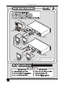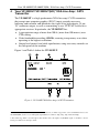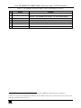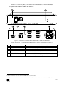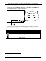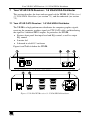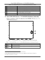
1
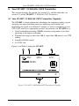
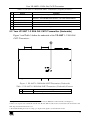
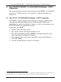
Kramer Electronics, Ltd.
USER MANUAL
Models:
VP-200XLT, XGA Line Amp / CAT5 Transmitter
VP-200XLT(HD), XGA Line Amp / CAT5 Transmitter
VP-300T, 1:2 XGA DA/CAT5 Transmitter
VP-5T, 1:4 VGA/UXGA Distributor/CAT5 Transmitter
VP-5T(HD), 1:4 VGA/UXGA Distributor/CAT5 Transmitter
VP-5R, CAT5 Receiver / 1:5 VGA/UXGA Distributor
Contents
Contents
1
2
2.1
3
3.1
3.2
3.3
4
5
5.1
5.2
6
6.1
6.2
7
7.1
7.2
8
9
10
10.1
11
Introduction
Getting Started
Quick Start
Overview
About the Power Connect Feature
Shielded Twisted Pair (STP) / Unshielded Twisted Pair (UTP)
Recommendations for Achieving the Best Performance
Your VP-200XLT/VP-200XLT(HD) XGA Line Amp / CAT5 Transmitter
Your VP-300T 1:2 XGA DA/ CAT5 Transmitter
Your VP-300T 1:2 XGA DA/ CAT5 Transmitter (Topside)
Your VP-300T 1:2 XGA DA/ CAT5 Transmitter (Underside)
Your VP-5T/VP-5T(HD) 1:4 VGA/UXGA Distributor / CAT5 Transmitter
Your VP-5T 1:4 VGA/UXGA Distributor / CAT5 Transmitter
Your VP-5T/VP5T(HD) (Underside)
Your VP-5R CAT5 Receiver / 1:5 VGA/UXGA Distributor
Your VP-5R CAT5 Receiver / 1:5 VGA/UXGA Distributor
Your VP-5R CAT5 Receiver / 1:5 VGA/UXGA Distributor (Underside)
Connecting the VP-200XLT
Connecting the VP-300T
Connecting the VP-5T and the VP-5R
Wiring the CAT5 LINE IN / LINE OUT RJ-45 Connectors
Technical Specifications
1
1
1
4
4
5
5
6
8
8
9
10
10
12
13
13
14
15
17
19
21
22
Figures
Figure 1: VP-200XLT XGA Line Amp / CAT5 Transmitter
Figure 2: VP-300T 1:2 XGA DA/ CAT5 Transmitter (Topside)
Figure 3: VP-300T 1:2 XGA DA/ CAT5 Transmitter (Underside)
Figure 4: VP-5T 1:4 VGA/UXGA Distributor / CAT5 Transmitter
Figure 5: VP-5T 1:4 VGA/UXGA Distributor / CAT5 Transmitter (Underside)
Figure 6: VP-5R CAT5 Receiver / 1:5 VGA/UXGA Distributor
Figure 7: VP-5R CAT5 Receiver / 1:5 VGA/UXGA Distributor (Underside)
Figure 8: Connecting the VP-200XLT
Figure 9: Connecting the VP-300T
Figure 10: Connecting the VP-5T and the VP-5R
Figure 11: CAT5 PINOUT
6
8
9
11
12
13
14
16
18
20
21
i
Contents
Tables
Table 1: VP-200XLT XGA Line Amp / CAT5 Transmitter Features
Table 2: VP-300T 1:2 XGA DA/ CAT5 Transmitter (Topside) Features
Table 3: VP-300T 1:2 XGA DA/ CAT5 Transmitter (Underside) Features
Table 4: VP-5T 1:4 VGA/UXGA Distributor / CAT5 Transmitter Features
Table 5: VP-5T 1:4 VGA/UXGA Distributor / CAT5 Transmitter (Underside) Features
Table 6: VP-5R CAT5 Receiver / 1:5 VGA/UXGA Distributor Features
Table 7: VP-5R CAT5 Receiver / 1:5 VGA/UXGA Distributor (Underside) Features
Table 8: CAT5 PINOUT
Table 9: Technical Specifications of the VP-200XLT (with 30m CAT5 cable)
Table 10: Technical Specifications of the VP-300T (with 30m CAT5 cable)
Table 11: Technical Specifications of the VP-5T/VP-5T(HD) (with 60m CAT5 cable)
Table 12: Technical Specifications of the VP-5R (with 30m CAT5 cable)
ii
7
9
9
11
12
14
14
21
22
22
23
23
KRAMER: SIMPLE CREATIVE TECHNOLOGY
Introduction
1
Introduction
Welcome to Kramer Electronics (since 1981): a world of unique, creative and
affordable solutions to the infinite range of problems that confront the video, audio
and presentation professional on a daily basis. In recent years, we have redesigned
and upgraded most of our line, making the best even better! Our 500-plus
different models now appear in 8 Groups1, which are clearly defined by function.
Congratulations on purchasing your Kramer: VP-200XLT, VP-200XLT(HD)
XGA Line Amp / CAT5 Transmitter, VP-300T 1:2 XGA DA/ CAT5
Transmitter, VP-5T, VP-5T(HD) 1:4 VGA/UXGA Distributor / CAT5
Transmitter, and/or VP-5R CAT5 Receiver / 1:5 VGA/UXGA Distributor,
which are ideal for:
Presentation and multimedia applications
Long range graphics distribution for schools, hospitals, security, and stores
The package includes this user manual2, and one or more of the following:
VP-200XLT/(HD)3, and/or VP-300T3, and/or VP-5T/(HD)4, and/or
VP-5R4
2
Getting Started
We recommend that you:
Unpack the equipment carefully and save the original box and packaging
materials for possible future shipment
Review the contents of this user manual
Use Kramer high performance high resolution cables5
2.1 Quick Start
The quick start charts summarize the basic setup and operation steps of the
VP-200XLT, the VP-300T and the VP-5T/VP-5R.
1 GROUP 1: Distribution Amplifiers; GROUP 2: Video and Audio Switchers, Matrix Switchers and Controllers; GROUP 3:
Video, Audio, VGA/XGA Processors; GROUP 4: Interfaces and Sync Processors; GROUP 5: Twisted Pair Interfaces;
GROUP 6: Accessories and Rack Adapters; GROUP 7: Scan Converters and Scalers; and GROUP 8: Cables and Connectors
2 Download up-to-date Kramer user manuals from the Internet at this URL: http://www.kramerelectronics.com
3 With a power adapter
4 With a power cord
5 The complete list of Kramer cables is on our Web site at http://www.kramerelectronics.com
1
Getting Started
VP-200XLT
1
1
2
3
Long line
3
1
Computer
Graphics Source
2
Projector
TP-120
Display
1
1
2
2
3
Display
2
4
4
Projector
3
Display
2
TP-120
Computer
Graphics Source
KRAMER: SIMPLE CREATIVE TECHNOLOGY
Getting Started
1
2
3
4
1
Computer
Graphics Source
VP-5T
2
Local
Display 1
Local
Display 4
4
VP-5R*
3
Display 1
Display 5
* Located up to 300ft (>100 meters)
away from the Computer Graphics
Source
3
Overview
3
Overview
This user manual describes the following products:
Kramer TOOLS VP-200XLT XGA Line Amp / CAT5 Transmitter, which
accepts one computer graphics input and distributes the signal to its
high-density 15 pin “D” connector output, as well as transmitting it over
UTP cabling (CAT5 or similar) to its appropriate receiver, see section 4
Kramer TOOLS VP-300T 1:2 XGA DA/ CAT5 Transmitter, which is a
distributor for computer graphics signals, accepting one input and
distributing the signal to its identical 2 outputs, as well as transmitting it
over CAT5 UTP cable to its appropriate receiver, see section 5
Kramer VP-5T/VP-5T(HD) 1:4 VGA/UXGA Distributor / CAT5
Transmitter, which is a distributor for computer graphics signals,
accepting one input, and distributing the signal to its identical 4 outputs,
as well as transmitting it over CAT5 UTP cable to its appropriate receiver,
see section 6
Kramer VP-5R CAT5 Receiver / 1:5 VGA/UXGA Distributor, which is a
distributor for computer graphics signals, receiving the computer graphics
signal via CAT5 UTP cable, and distributing the signal to 5 identical
HD15 outputs, see section 7
This section describes:
The power connect feature, see section 3.1
Using shielded twisted pair (STP) / unshielded twisted pair (UTP), see
section 3.2
Recommendations for achieving the best performance, see section 3.3
3.1 About the Power Connect Feature
The Power Connect feature lets you power a transmitter / receiver system by
connecting just one power adapter— to either the transmitter or the receiver.
The other unit is fed via the cable connecting between the transmitter/receiver.
The Power Connect feature applies as long as the cable can carry power. The
distance does not exceed 50 meters on standard CAT5 cable, for longer
distances, heavy gauge cable should be used1.
For a CAT5 cable exceeding a distance of 50 meters, separate power supplies
should be connected to the transmitter and to the receiver simultaneously.
1 CAT5 cable is still suitable for the video/audio transmission, but not for feeding the power at these distances
4
KRAMER: SIMPLE CREATIVE TECHNOLOGY
Overview
3.2 Shielded Twisted Pair (STP) / Unshielded Twisted Pair (UTP)
The decision whether to use shielded twisted pair (STP) cable or unshielded
twisted pair (UTP) cable depends on the nature of the application.
It is recommended that in applications with high interference, shielded twisted
pair (STP) cable is used. However, the shield itself does create a capacitance
that degrades the frequency response of the machines. For shorter distances, of
50m or so, shielded twisted pair (STP) cable is preferred because it provides
protection from interference (degradation is not apparent).
For long range applications, unshielded twisted pair (UTP) cable is preferred.
However, the unshielded twisted pair (UTP) cable should be installed far away from
electric cables, motors and so on, which are prone to create electrical interference.
3.3 Recommendations for Achieving the Best Performance
To achieve the best performance:
Connect only good quality connection cables, thus avoiding interference,
deterioration in signal quality due to poor matching, and elevated noiselevels (often associated with low quality cables)
Avoid interference from neighboring electrical appliances and position your
Kramer machines away from moisture, excessive sunlight and dust
Caution – No operator-serviceable parts inside unit.
Warning – Use only the Kramer Electronics input power
wall adapter that is provided with this unit1.
Warning – Disconnect power and unplug unit from wall
before installing or removing device or servicing unit.
1 For example: model number AD2512C, part number 2535-000251
5
Your VP-200XLT/VP-200XLT(HD) XGA Line Amp / CAT5 Transmitter
4
Your VP-200XLT/VP-200XLT(HD)1 XGA Line Amp / CAT5
Transmitter
The VP-200XLT is a high performance XGA line amp / CAT5 transmitter
that accepts one computer graphics (XGA2) input, provides necessary
buffering and isolation, and distributes the signal to its high-density 15 pin
“D” connector output, as well as transmitting it over UTP CAT5 cable to its
appropriate receiver. In particular, the VP-200XLT has:
A transmission range of more than 300 ft. (more than 100 meters) over
UTP cabling
Video bandwidth exceeding 400MHz, ensuring transparency even when
operating at the highest resolutions
Output level control, and cable equalization, using two rotary controls on
the side panel of the machine
Figure 1 and Table 1 define the VP-200XLT:
Figure 1: VP-200XLT XGA Line Amp / CAT5 Transmitter
1 The VP-200XLT(HD) (identified by a sticker on its underside) is similar in appearance to the VP-200XLT. However, the
VP-200XLT(HD) can also receive HD signals (high definition resolutions: 480p, 576p, 720p, 1080i and 1080p)
2 The terminology XGA is used throughout this manual, where this implies any RGBHV signal on an HD15 connector
having a resolution from VGA up to XGA
6
KRAMER: SIMPLE CREATIVE TECHNOLOGY
Your VP-200XLT/VP-200XLT(HD) XGA Line Amp / CAT5 Transmitter
Table 1: VP-200XLT XGA Line Amp / CAT5 Transmitter Features
#
Feature
Function
1 12V DC
+12V DC connector for powering the unit
1
2 LINE OUT RJ-45 Connector Connects to the LINE IN RJ-45 connector on the TP-120 XGA Line
2
Receiver or the VP-5R CAT5 Receiver / 1:5 VGA/UXGA Distributor
3 XGA OUT HD15F Connector Connect to the XGA acceptor
4 INPUT HD15F Connector
Connect to the XGA source
5 LEVEL Control knob
Rotate to adjust the output signal level
6 EQ. Control knob
Rotate to adjust the video EQ. (equalization) compensation
7 ON LED
Illuminates when receiving power
1 Using a UTP CAT5 cable with RJ-45 connectors at both ends (the PINOUT is defined in Table 8 and Figure 11)
2 Refer to the separate user manual: PT-110, PT-120, TP-120, WP-110, which can be downloaded from the Internet at this
URL: http://www.kramerelectronics.com
7
Your VP-300T 1:2 XGA DA/ CAT5 Transmitter
5
Your VP-300T 1:2 XGA DA/ CAT5 Transmitter
This section describes the topside (see section 5.1), and the underside (see
section 5.2) of the VP-300T 1:2 XGA DA/ CAT5 Transmitter.
5.1 Your VP-300T 1:2 XGA DA/ CAT5 Transmitter (Topside)
The VP-300T is a high performance distributor for computer graphics signals,
accepting one input, providing necessary buffering and isolation, and
distributing the signal to its identical 2 outputs, as well as transmitting it over
UTP CAT5 cable to its appropriate receiver. In particular, the VP-300T has a:
Video bandwidth exceeding 430MHz, ensuring transparency even when
operating at the highest resolutions
Transmission range of more than 300 ft. (more than 100 meters) over UTP
cabling
Switch for ID Bit control
Is 12VDC fed
Figure 2 and Table 2 define the VP-300T:
Figure 2: VP-300T 1:2 XGA DA/ CAT5 Transmitter (Topside)
8
KRAMER: SIMPLE CREATIVE TECHNOLOGY
Your VP-300T 1:2 XGA DA/ CAT5 Transmitter
Table 2: VP-300T 1:2 XGA DA/ CAT5 Transmitter (Topside) Features
#
Feature
Function
1 12V DC
+12V DC connector for powering the unit
1
2 LINE OUT RJ-45 Connector Connects to the LINE IN RJ-45 connector on the TP-120 XGA Line
2
Receiver or the VP-5R CAT5 Receiver / 1:5 VGA/UXGA Distributor
3 OUTPUT 2 HD15F Connector Connect to the XGA acceptor 2
4 OUTPUT 1 HD15F Connector Connect to the XGA acceptor 1
5 XGA INPUT HD15F Connector Connect to the XGA source
6 ON LED
Illuminates when receiving power
5.2 Your VP-300T 1:2 XGA DA/ CAT5 Transmitter (Underside)
Figure 3 and Table 3 define the underside of the VP-300T 1:2 XGA DA/
CAT5 Transmitter:
Figure 3: VP-300T 1:2 XGA DA/ CAT5 Transmitter (Underside)
Table 3: VP-300T 1:2 XGA DA/ CAT5 Transmitter (Underside) Features
#
Feature
1 ID Bit Switch
Function
Slide to the right to set to ON3; to the left to set to OFF
1 Using a UTP CAT5 cable with RJ-45 connectors at both ends (the PINOUT is defined in Table 8 and Figure 11)
2 Refer to the separate user manual: PT-110, PT-120, TP-120, WP-110, which can be downloaded from the Internet at this
URL: http://www.kramerelectronics.com
3 The default. Enabling the notebook or laptop to output a VGA signal to an external VGA monitor
9
Your VP-5T/VP-5T(HD ) 1:4 VGA/UXGA Distributor / CAT5 Transmitter
6
Your VP-5T/VP-5T(HD1) 1:4 VGA/UXGA Distributor / CAT5
Transmitter
This section describes the front and rear panels of the VP-5T 1:4 VGA/UXGA
Distributor / CAT5 Transmitter (see section 6.1), and the underside (see
section 6.2).
6.1 Your VP-5T 1:4 VGA/UXGA Distributor / CAT5 Transmitter
The VP-5T is a high performance distributor for computer graphics signals,
accepting one input, providing necessary buffering and isolation, and
distributing the signal to its identical 4 outputs, as well as transmitting it over
UTP CAT5 cable to its appropriate receiver.
In particular, the VP-5T:
Features front panel EQ. control
Has switches on the underside for ID Bit control
Has video bandwidth exceeding 440MHz, ensuring transparency even
when operating at the highest resolutions
Has a transmission range of more than 300 ft. (more than 100 meters)
over UTP cabling
Is mains fed and housed in a half 19" enclosure
1 The VP-5T(HD) (identified by the Hs and Vs switches on its underside) is similar in appearance to the VP-5T. However,
the VP-5T(HD) can also receive HD signals (high definition resolutions: 480p, 576p, 720p, 1080i and 1080p)
10
KRAMER: SIMPLE CREATIVE TECHNOLOGY
Your VP-5T/VP-5T(HD ) 1:4 VGA/UXGA Distributor / CAT5 Transmitter
Figure 4 and Table 4 define the VP-5T:
Figure 4: VP-5T 1:4 VGA/UXGA Distributor / CAT5 Transmitter
Table 4: VP-5T 1:4 VGA/UXGA Distributor / CAT5 Transmitter Features
1
2
3
4
#
Feature
POWER Switch
EQ. Trimmer
INPUT HD15F Connector
CAT5 OUT RJ-45 Connector
5
6
OUTPUT HD15F Connector
Power Connector with FUSE
Function
Illuminated switch for turning the unit ON or OFF
Adjusts1 the video EQ. (equalization) compensation
Connect to the VGA/UXGA source
Connect to2 the LINE IN RJ-45 connector on the VP-5R CAT5
Receiver / 1:5 VGA/UXGA Distributor
Connect to the VGA/UXGA acceptor (from 1 to 4)
AC connector enabling power supply to the unit
1 Insert a screwdriver into the hole and carefully rotate it, to trim the level
2 Using a UTP CAT5 cable with RJ-45 connectors at both ends (the PINOUT is defined in Table 8 and Figure 11)
11
Your VP-5T/VP-5T(HD ) 1:4 VGA/UXGA Distributor / CAT5 Transmitter
6.2 Your VP-5T/VP5T(HD) (Underside)
Figure 5 and Table 5 define the underside of the VP-5T/VP-5T(HD) 1:4
VGA/UXGA Distributor / CAT5 Transmitter:
Figure 5: VP-5T 1:4 VGA/UXGA Distributor / CAT5 Transmitter (Underside)
Table 5: VP-5T 1:4 VGA/UXGA Distributor / CAT5 Transmitter (Underside) Features
4
Feature
Function
PIN 11 ID BIT CONTROL Switch Slide to the left to set to ON1; to the right to set to OFF
PIN 4 ID BIT CONTROL Switch Slide to the left to set to ON1; to the right to set to OFF
VS Switch
Slide the switch to the left to change the VS polarity to
negative polarity2; slide the switch to the right to retain the
polarity (default)
HS Switch
Slide the switch to the left to change the HS polarity to
negative polarity2; slide the switch to the right to retain the
polarity (default)
HD ONLY
#
1
2
3
1 The default. Enabling the notebook or laptop to output a VGA signal to an external VGA monitor
2 Downgoing syncs
12
KRAMER: SIMPLE CREATIVE TECHNOLOGY
Your VP-5R CAT5 Receiver / 1:5 VGA/UXGA Distributor
7
Your VP-5R CAT5 Receiver / 1:5 VGA/UXGA Distributor
This section describes the front and rear panels of the VP-5R CAT5 Receiver /
1:5 VGA/UXGA Distributor (see section 7.1), and the underside (see section
7.2).
7.1 Your VP-5R CAT5 Receiver / 1:5 VGA/UXGA Distributor
The VP-5R is a high performance distributor for computer graphics signals,
receiving the computer graphics signal via UTP CAT5 cable, and distributing
the signal to 5 identical HD15 outputs. In particular, the VP-5R:
Features front panel line input level and EQ. control, as well as output
EQ. control
Is mains fed
Is housed in a half 19" enclosure
Figure 6 and Table 6 define the VP-5R:
Figure 6: VP-5R CAT5 Receiver / 1:5 VGA/UXGA Distributor
13
Your VP-5R CAT5 Receiver / 1:5 VGA/UXGA Distributor
Table 6: VP-5R CAT5 Receiver / 1:5 VGA/UXGA Distributor Features
#
1
2
3
4
5
Feature
POWER Switch
LINE INPUT LEVEL Trimmer
LINE INPUT EQ. Trimmer
OUTPUT EQ. Trimmer
CAT5 LINE IN RJ-45 Connector
6
7
OUTPUT HD15F Connector
Power Connector with FUSE
Function
Illuminated switch for turning the unit ON or OFF
1
Adjusts the video input level
1
Adjusts the video input EQ. (equalization) compensation
1
Adjusts the video output EQ. (equalization) compensation
Connect to2 the LINE OUT RJ-45 connector on the VP-5T 1:4
VGA/UXGA Distributor / CAT5 Transmitter
Connect to the VGA/UXGA acceptor (from 1 to 5)
AC connector enabling power supply to the unit
7.2 Your VP-5R CAT5 Receiver / 1:5 VGA/UXGA Distributor (Underside)
Figure 7 and Table 7 define the underside of the VP-5R CAT5 Receiver / 1:5
VGA/UXGA Distributor:
Figure 7: VP-5R CAT5 Receiver / 1:5 VGA/UXGA Distributor (Underside)
Table 7: VP-5R CAT5 Receiver / 1:5 VGA/UXGA Distributor (Underside) Features
#
Feature
1 V SYNC
Switch
2 H SYNC
Switch
Function
Slide the switch to the right3 to change the V SYNC polarity; slide the switch to the
left to retain the polarity
3
Slide the switch to the right to change the H SYNC polarity; slide the switch to the
left to retain the polarity
1 Insert a screwdriver into the hole and carefully rotate it, to trim the level
2 Using a UTP CAT5 cable with RJ-45 connectors at both ends (the PINOUT is defined in Table 8 and Figure 11)
3 By default, both switches are set to the left
14
KRAMER: SIMPLE CREATIVE TECHNOLOGY
Connecting the VP-200XLT
8
Connecting the VP-200XLT
You can use the VP-200XLT and, for example, the TP-120 to configure an XGA
Line-to-Twisted Pair Transmitter and Receiver system.
To connect the VP-200XLT with the TP-120, as the example in Figure 8
illustrates, do the following:
1. On the VP-200XLT XGA Line Amp / CAT5 Transmitter, connect the:
Computer graphics (XGA) source (for example, a computer) to the
INPUT HD15F connector
XGA OUT HD15F connector to the acceptor (for example, to a
projector)
2. On the TP-120 XGA Line Receiver, connect the XGA OUT HD15F connector
to the XGA acceptor (for example, a display).
3. Connect the LINE OUT RJ-45 connector on the VP-200XLT to the LINE IN
RJ-45 connector on the TP-120, via UTP cabling (with a range of more than
300ft (more than 100 meters)), see section 10.1.
4. Connect the 12V DC power adapter to the power socket on the VP-200XLT,
and plug the adapter into the mains electricity socket. Similarly, connect the
other 12V DC power adapter to the power socket on the TP-120, and plug that
adapter into the mains electricity socket.
5. On the VP-200XLT, if required, rotate the appropriate control knob to adjust
the:
Video output signal level
Cable compensation equalization level
6. On the TP-120, if required:
Adjust1 the video output signal level and/or cable compensation
equalization level
Set the H SYNC and V SYNC switches2, on the underside
1 Use a screwdriver to carefully rotate the trimmer, adjusting the appropriate level
2 By default, both switches are set down (for normal V SYNC and H SYNC polarity)
15
Connecting the VP-200XLT
Figure 8: Connecting the VP-200XLT
16
KRAMER: SIMPLE CREATIVE TECHNOLOGY
Connecting the VP-300T
9
Connecting the VP-300T
You can use the VP-300T and, for example, the TP-120 to configure an XGA
Line-to-Twisted Pair Transmitter and Receiver system.
To connect the VP-300T with the TP-120, as the example in Figure 9
illustrates, do the following:
1. On the VP-300T 1:2 XGA DA/ CAT5 Transmitter, connect the:
Computer graphics (XGA) source (for example, a computer) to the
INPUT HD15F connector
OUTPUT 1 and OUTPUT 2 HD15F connectors to up to1 two
acceptors (for example, to a display and to a projector, respectively)
2. On the TP-120 XGA Line Receiver, connect the XGA OUT HD15F connector
to the XGA acceptor (for example, a display).
3. Connect the LINE OUT RJ-45 connector on the VP-300T to the LINE IN
RJ-45 connector on the TP-120, via UTP cabling (with a range of more than
300ft (more than 100 meters)), see section 10.1.
4. Connect the 12V DC power adapter to the power socket on the VP-300T, and
plug the adapter into the mains electricity socket. Similarly, connect the other
12V DC power adapter to the power socket on the TP-120, and plug that
adapter into the mains electricity socket.
5. On the VP-300T, if required:
Set the ID Bit switch
6. On the TP-120, if required:
Adjust2 the video output signal level and/or cable compensation
equalization level
Set the H SYNC and V SYNC switches3, on the underside
1 When both outputs are not required, connect only the output that is required and leave the other output unconnected
2 Use a screwdriver to carefully rotate the trimmer, adjusting the appropriate level
3 By default, both switches are set down (for normal V SYNC and H SYNC polarity)
17
Connecting the VP-300T
Figure 9: Connecting the VP-300T
18
KRAMER: SIMPLE CREATIVE TECHNOLOGY
Connecting the VP-5T and the VP-5R
10 Connecting the VP-5T and the VP-5R
You can use the VP-5T 1:4 VGA/UXGA Distributor / CAT5 Transmitter and
the VP-5R CAT5 Receiver / 1:5 VGA/UXGA Distributor to configure an XGA
Line-to-Twisted Pair Transmitter and Receiver system.
To connect the VP-5T with the VP-5R, as the example in Figure 10
illustrates, do the following:
1. On the VP-5T, connect the computer graphics source (for example, a
computer) to the INPUT HD15F connector, and connect up to1 4 acceptors
(for example, local displays) to the OUTPUT HD15F connectors 1 to 4.
2. On the VP-5R, connect up to1 5 acceptors (for example, displays) to the
OUTPUT HD15F connectors 1 to 5.
3. Connect the CAT5 OUT RJ-45 connector on the VP-5T to the CAT5 LINE
IN RJ-45 connector on the VP-5R, via UTP cabling (with a range of more
than 300ft (more than 100 meters)), see section 10.1.
4. Connect the power cord2 (not illustrated in Figure 10) to the VP-5T, and
connect the other power cord2 to the VP-5R.
5. On the VP-5T, if required:
Adjust3 the front panel cable compensation equalization level
Set the underside ID BIT Control switches
On the VP-5T(HD) only, set the H SYNC and V SYNC switches4 on
the underside
6. On the VP-5R, if required:
Adjust3 the front panel LINE INPUT signal level and/or cable
compensation equalization level, and/or OUTPUT compensation
equalization level
Set the V SYNC and H SYNC switches4, on the underside
1 When not all the outputs are required, connect only those that are required and leave the other output(s) unconnected
2 We recommend that you use only the power cord that is supplied with each specific machine
3 Use a screwdriver to carefully rotate the trimmer, adjusting the appropriate level
4 By default, both switches are set down (for negative V SYNC and H SYNC polarity)
19
Connecting the VP-5T and the VP-5R
Figure 10: Connecting the VP-5T and the VP-5R
20
KRAMER: SIMPLE CREATIVE TECHNOLOGY
Connecting the VP-5T and the VP-5R
10.1
Wiring the CAT5 LINE IN / LINE OUT RJ-45 Connectors
Table 8 and Figure 11 define the UTP CAT5 PINOUT, using a straight pin to
pin cable with RJ-45 connectors:
Figure 11: CAT5 PINOUT
Table 8: CAT5 PINOUT
EIA /TIA 568A
PIN
1
2
3
4
5
6
7
8
Wire Color
Green / White
Green
Orange / White
Blue
Blue / White
Orange
Brown / White
Brown
EIA /TIA 568B
PIN
1
2
3
4
5
6
7
8
Wire Color
Orange / White
Orange
Green / White
Blue
Blue / White
Green
Brown / White
Brown
Pair 1
4 and 5
Pair 1
Pair 2
3 and 6
Pair 2
4 and 5
1 and 2
Pair 3
Pair 4
1 and 2
7 and 8
Pair 3
Pair 4
3 and 6
7 and 8
21
Technical Specifications
11 Technical Specifications1
This section includes the technical specifications of the VP-200XLT/
VP-200XLT(HD) (see Table 9), the VP-300T (see Table 10), the
VP-5T/VP-5T(HD) (see Table 11), and the VP-5R (see Table 12).
Table 9: Technical Specifications of the VP-200XLT (with 30m CAT5 cable)
INPUTS:
OUTPUTS:
MAX. OUTPUT LEVEL2:
BANDWIDTH (-3dB):
RESOLUTION:
DIFF. GAIN2:
2
DIFF. PHASE :
2
K-FACTOR :
S/N RATIO2:
CONTROLS2:
COUPLING2:
POWER SOURCE:
DIMENSIONS:
WEIGHT:
ACCESSORIES:
1 XGA on an HD15 connector
1 XGA on an HD15 connector; 1 RJ-45 connector
1.9Vpp (XGA), 1.9Vpp (CAT5)
407MHz (XGA), 155MHz (CAT5)
3
Up to UXGA, up to 1080p
0.03% (XGA), 3.5% (CAT5)
0.03 Deg (XGA), 0.51 Deg (CAT5)
<0.05% (XGA and CAT5)
74dB (XGA), 71dB (CAT5)
LEVEL: –1.5dB to +2.5dB (from VP-200XLT) (XGA); –1dB to +2.5dB (from
VP-200XLT); –7.7dB to +9dB (from TP-120) (CAT5)
EQ.: 0 to 4.1dB @50MHz (from VP-200XLT) (XGA); 0 to 4dB (from VP-200XLT),
0 to 30.4dB @50MHz (from TP-120) (CAT5)
DC (XGA), AC (CAT5)
12 VDC 140mA
12cm x 7.5cm x 2.5cm (4.7" x 2.95" x 0.98", W, D, H)
0.3 kg. (0.67 lbs.) approx.
Power supply
Table 10: Technical Specifications of the VP-300T (with 30m CAT5 cable)
INPUTS:
OUTPUTS:
1 XGA on an HD15 connector
2 XGA on HD15 connectors
1 RJ-45 connector
4
MAX. OUTPUT LEVEL : 1.9Vpp (XGA), 1.3Vpp (CAT5)
BANDWIDTH (-3dB):
439MHz (XGA), 152MHz (CAT5)
DIFF. GAIN4:
0.05% (XGA), 3.1% (CAT5)
DIFF. PHASE4:
0.05 Deg (XGA), 0.4 Deg (CAT5)
K-FACTOR4:
<0.05% (XGA and CAT5)
4
S/N RATIO :
76dB (XGA), 71dB (CAT5)
4
CONTROLS :
LEVEL: –8.9dB to 3.9dB (CAT5)
EQ.: 0 to 30dB (CAT5)
COUPLING4:
DC (XGA), AC (CAT5)
POWER SOURCE:
12 VDC 130mA
DIMENSIONS:
12cm x 7.5cm x 2.5cm (4.7" x 2.95" x 0.98", W, D, H)
WEIGHT:
0.3 kg. (0.67 lbs.) approx.
ACCESSORIES:
Power supply
1 Specifications are subject to change without notice
2 For the VP-200XLT to TP-120 SETUP
3 The HD resolutions apply to the HD version of the machine
4 For the VP-300T to TP-120 SETUP
22
KRAMER: SIMPLE CREATIVE TECHNOLOGY
Technical Specifications
Table 11: Technical Specifications of the VP-5T/VP-5T(HD) (with 60m CAT5 cable)
INPUTS:
OUTPUTS:
1 XGA on an HD15 connector
4 XGA on HD15 connectors
1 RJ-45 connector
MAX. OUTPUT LEVEL1: 1.7Vpp (XGA), 1.7Vpp (CAT5)
BANDWIDTH (-3dB):
445MHz (XGA), 154MHz (CAT5)
2
RESOLUTION:
Up to UXGA, up to 1080p
DIFF. GAIN1:
0.8% (XGA), 3.2% (CAT5)
1
DIFF. PHASE :
0.08 Deg (XGA), 0.06 Deg (CAT5)
1
K-FACTOR :
0.1% (XGA), <0.05% (CAT5)
1
S/N RATIO :
76dB (XGA), 73dB (CAT5)
1
CONTROLS :
LEVEL: –7.4dB to 3.5dB (CAT5)
EQ.: 0 to 37.8dB @50MHz (CAT5)
1
COUPLING :
DC (XGA), AC (CAT5)
POWER SOURCE:
230 VAC, 50/60 Hz. (115VAC, U.S.A.) 13VA
DIMENSIONS:
22cm x 18cm x 4.5cm (8.7” x 7” x 1.7”) W, D, H (half 19”, 1U)
WEIGHT:
1.2kg (2.6 lbs) approx.
ACCESSORIES:
Power cord
Table 12: Technical Specifications of the VP-5R (with 30m CAT5 cable)
INPUTS:
OUTPUTS:
MAX. OUTPUT LEVEL3:
BANDWIDTH (-3dB):
DIFF. GAIN3:
DIFF. PHASE3:
K-FACTOR3:
S/N RATIO3:
CONTROLS3:
COUPLING3:
POWER SOURCE:
DIMENSIONS:
WEIGHT:
ACCESSORIES:
1 RJ-45 connector
5 XGA on HD15 connectors
1.4Vpp
150MHz
3.4%
0.05 Deg
<0.05%
74dB
LEVEL: –8.2dB to 4.3dB
LINE EQ.: 0 to 30dB; OUT EQ.: 0 to 8.6dB
AC
230 VAC, 50/60 Hz. (115VAC, U.S.A.) 9.2VA
22cm x 18cm x 4.5cm (8.7” x 7” x 1.7”) W, D, H (half 19”, 1U)
1.2kg (2.6 lbs) approx.
Power cord
1 For the VP-5T to TP-120 SETUP
2 The HD resolutions apply to the HD version of the machine
3 For the VP-5R to WP-110 SETUP
23
LIMITED WARRANTY
Kramer Electronics (hereafter Kramer) warrants this product free from defects in material and workmanship under the
following terms.
HOW LONG IS THE WARRANTY
Labor and parts are warranted for seven years from the date of the first customer purchase.
WHO IS PROTECTED?
Only the first purchase customer may enforce this warranty.
WHAT IS COVERED AND WHAT IS NOT COVERED
Except as below, this warranty covers all defects in material or workmanship in this product. The following are not covered
by the warranty:
1.
2.
3.
Any product which is not distributed by Kramer, or which is not purchased from an authorized Kramer dealer. If you are
uncertain as to whether a dealer is authorized, please contact Kramer at one of the agents listed in the web site
www.kramerelectronics.com.
Any product, on which the serial number has been defaced, modified or removed.
Damage, deterioration or malfunction resulting from:
i)
Accident, misuse, abuse, neglect, fire, water, lightning or other acts of nature
ii)
Product modification, or failure to follow instructions supplied with the product
iii)
Repair or attempted repair by anyone not authorized by Kramer
iv)
Any shipment of the product (claims must be presented to the carrier)
v)
Removal or installation of the product
vi)
Any other cause, which does not relate to a product defect
vii)
Cartons, equipment enclosures, cables or accessories used in conjunction with the product
WHAT WE WILL PAY FOR AND WHAT WE WILL NOT PAY FOR
We will pay labor and material expenses for covered items. We will not pay for the following:
1.
2.
3.
Removal or installations charges.
Costs of initial technical adjustments (set-up), including adjustment of user controls or programming. These costs are the
responsibility of the Kramer dealer from whom the product was purchased.
Shipping charges.
HOW YOU CAN GET WARRANTY SERVICE
1.
2.
3.
To obtain service on you product, you must take or ship it prepaid to any authorized Kramer service center.
Whenever warranty service is required, the original dated invoice (or a copy) must be presented as proof of warranty coverage,
and should be included in any shipment of the product. Please also include in any mailing a contact name, company, address, and
a description of the problem(s).
For the name of the nearest Kramer authorized service center, consult your authorized dealer.
LIMITATION OF IMPLIED WARRANTIES
All implied warranties, including warranties of merchantability and fitness for a particular purpose, are limited in duration to
the length of this warranty.
EXCLUSION OF DAMAGES
The liability of Kramer for any effective products is limited to the repair or replacement of the product at our option. Kramer
shall not be liable for:
1.
2.
Damage to other property caused by defects in this product, damages based upon inconvenience, loss of use of the product, loss
of time, commercial loss; or:
Any other damages, whether incidental, consequential or otherwise. Some countries may not allow limitations on how long an
implied warranty lasts and/or do not allow the exclusion or limitation of incidental or consequential damages, so the above
limitations and exclusions may not apply to you.
This warranty gives you specific legal rights, and you may also have other rights, which vary from place to place.
NOTE: All products returned to Kramer for service must have prior approval. This may be obtained from your dealer.
This equipment has been tested to determine compliance with the requirements of:
EN-50081:
"Electromagnetic compatibility (EMC);
generic emission standard.
Part 1: Residential, commercial and light industry"
EN-50082:
"Electromagnetic compatibility (EMC) generic immunity standard.
Part 1: Residential, commercial and light industry environment".
CFR-47:
FCC Rules and Regulations:
Part 15: “Radio frequency devices
Subpart B – Unintentional radiators”
CAUTION!
Servicing the machines can only be done by an authorized Kramer technician. Any user who makes changes or modifications to
the unit without the expressed approval of the manufacturer will void user authority to operate the equipment.
Use the supplied DC power supply to feed power to the machine.
Please use recommended interconnection cables to connect the machine to other components.
24
KRAMER: SIMPLE CREATIVE TECHNOLOGY
For the latest information on our products and a list of Kramer
distributors, visit our Web site: www.kramerelectronics.com,
where updates to this user manual may be found.
We welcome your questions, comments and feedback.
Safety Warning:
Disconnect the unit from the power supply before
opening/servicing.
Caution
Kramer Electronics, Ltd.
Web site: www.kramerelectronics.com
E-mail: [email protected]
P/N: 2900-000067 REV 3