1
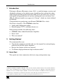
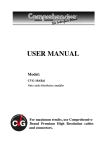
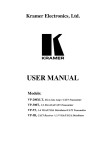
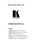
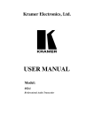
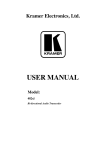
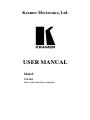
Kramer Electronics, Ltd. USER MANUAL Model: VM-10xl Video Audio Distribution Amplifier Contents Contents 1 2 2.1 3 4 5 6 6.1 6.2 7 Introduction Getting Started Quick Start Overview Your VM-10xl Video Audio Distribution Amplifier Installing on a Rack Using the VM-10xl Video Audio Distribution Amplifier Connecting a VM-10xl Video Audio Distribution Amplifier Increasing the Outputs Technical Specifications 1 1 1 3 3 6 7 7 9 11 Figures Figure 1: VM-10xl Video Audio Distribution Amplifier Figure 2: Connecting a single VM-10xl Video Audio Distribution Amplifier Figure : Increasing the Outputs: arranging a 1:30 Video Audio DA 4 8 10 Tables Table : Front Panel VM-10xl Video Audio Distribution Amplifier Features 5 Table : Rear Panel VM-10xl Video Audio Distribution Amplifier Features 5 Table : Technical Specifications of the VM-10xl Video Audio Distribution Amplifier 11 i Introduction 1 Introduction Welcome to Kramer Electronics (since 1981): a world of unique, creative and affordable solutions to the infinite range of problems that confront the video, audio and presentation professional on a daily basis. In recent years, we have redesigned and upgraded most of our line, making the best even better! Our 500-plus different models now appear in 8 Groups1, which are clearly defined by function. Congratulations on purchasing your Kramer VM-10xl Video Audio Distribution Amplifier. The VM-10xl is ideal for: Audio video duplication studios Rental/staging, CCTV, and home theater use Each package includes the following items: VM-10xl Video Audio Distribution Amplifier Power cord This user manual2 2 Getting Started We recommend that you: Unpack the equipment carefully and save the original box and packaging materials for possible future shipment Review the contents of this user manual Use Kramer high performance high resolution cables3 2.1 Quick Start This quick start chart summarizes the basic setup and operation steps. 1 GROUP 1: Distribution Amplifiers; GROUP 2: Video and Audio Switchers, Matrix Switchers and Controllers; GROUP 3: Video, Audio, VGA/XGA Processors; GROUP 4: Interfaces and Sync Processors; GROUP 5: Twisted Pair Interfaces; GROUP 6: Accessories and Rack Adapters; GROUP 7: Scan Converters and Scalers; and GROUP 8: Cables and Connectors 2 Download up-to-date Kramer user manuals from the Internet at this URL: http://www.kramerelectronics.com 3 The complete list of Kramer cables is on our Web site at http://www.kramerelectronics.com 1 Getting Started 2 KRAMER: SIMPLE CREATIVE TECHNOLOGY Overview 3 Overview The VM-10xl is a high quality 1:10 video audio distribution amplifier using BNC connectors for composite video, and RCA connectors for unbalanced stereo audio signals. The VM-10xl accepts a composite video input and distributes the signal to 10 identical outputs. In particular, the VM-10xl: Includes looping connectors for connecting to a local monitor, other acceptor, or for forming larger systems1 Has a video bandwidth of 360MHZ, ensuring transparent performance with typical video and audio sources Can function as unbalanced stereo audio or balanced2 mono audio (selected via an audio control button) Can output video signals that are DC or AC coupled for maximum flexibility (selected via a coupling button) Has front panel video trimmer controls3 for output level and cable equalization (EQ.), as well as audio trimmer controls for left and right gain, with an enable / disable control button Achieving the best performance means: Connecting only good quality connection cables, thus avoiding interference, deterioration in signal quality due to poor matching, and elevated noise levels (often associated with low quality cables) Avoiding interference from neighboring electrical appliances and positioning your VM-10xl away from moisture, excessive sunlight and dust 4 Your VM-10xl Video Audio Distribution Amplifier Figure 1 and Table 1 define the VM-10xl Video Audio Distribution Amplifier: 1 For example, you can connect 3 VM-10xl units to make a 1:30 video audio distribution amplifier. See section 6.2 for details 2 Recommended for low signal transmission over long distances or in audio broadcasting studios for high quality signal recreation 3 The video outputs are arranged in two blocks of 5 outputs (outputs 1 to 5, and outputs 6 to 10). Each block can be separately trimmed for output level and cable equalization (EQ.) thus achieving different compensations for different cable lengths 3 Your VM-10xl Video Audio Distribution Amplifier Figure 1: VM-10xl Video Audio Distribution Amplifier 4 KRAMER: SIMPLE CREATIVE TECHNOLOGY Your VM-10xl Video Audio Distribution Amplifier Table : Front Panel VM-10xl Video Audio Distribution Amplifier Features Feature Function POWER Switch BAL/ST Button Illuminated switch supplying power to the unit Pushing in selects balanced mono audio operation, releasing selects unbalanced stereo audio operation 1 LEFT GAIN Trimmer Adjusts the audio signal level for the left channel Enable/Disable Button Pushing in enables audio gain trimmer control, releasing bypasses it disabling audio gain trimmer control 5 RIGHT GAIN Trimmer Adjusts the audio signal level for the right channel 6 EQ. Trimmer Adjusts the video EQ. (equalization) compensation of outputs 6 to 10 LEVEL Trimmer Adjusts1 the video signal level of outputs 6 to 10 LEVEL Trimmer Adjusts1 the video signal level of outputs 1 to 5 EQ. Trimmer Adjusts the video EQ. (equalization) compensation of outputs 1 to 5 4 7 8 9 VIDEO CONTROL 3 AUDIO CONTROL # 1 2 1 1 1 Table : Rear Panel VM-10xl Video Audio Distribution Amplifier Features # 10 11 12 Feature VIDEO IN BNC Connector LOOP BNC Connector TERM Button 13 COUPLING Button 14 15 16 17 18 VIDEO OUT BNC Connectors AUDIO IN RCA Connectors AUDIO LOOP RCA Connectors AUDIO OUTPUTS RCA Connectors Power Connector with Fuse Function Connects to the video source For looping to increase output availability 2 Pushing in selects 75, releasing selects Hi-Z Pushing in selects DC coupling3, releasing selects AC coupling (removing the DC offset of the input signal) Connect to the video acceptors (from 1 to 10) Connects to the stereo audio source (R and L) For looping to increase audio output availability (R and L) Connect to the stereo audio acceptors R and L, from 1 to 10) AC connector enabling power supply to the unit 1 Insert a screwdriver into the hole and carefully rotate it, to trim the level 2 For looping select Hi-Z 3 Achieving the best linearity and signal fidelity 5 Installing on a Rack 5 Installing on a Rack This section describes what to do before installing on a rack and how to rack mount. Before Installing on a Rack Before installing on a rack, be sure that the environment is within the recommended range: How to Rack Mount To rack-mount a machine: 1 Attach both ear brackets to the machine. To do so, remove the screws from each side of the machine (3 on each side), and replace those screws through the ear brackets. 2 Place the ears of the machine against the rack rails, and insert the proper screws (not provided) through each of the four holes in the rack ears. Operating temperature range +5 to +45 Deg. Centigrade Operating humidity range 5 to 65% RHL, non-condensing Storage temperature range -20 to +70 Deg. Centigrade Storage humidity range 5 to 95% RHL, non-condensing CAUTION!! When installing on a 19" rack, avoid hazards by taking care that: 1 It is located within the recommended environmental conditions, as the operating ambient temperature of a closed or multi unit rack assembly may exceed the room ambient temperature. 2 Once rack mounted, enough air will still flow around the machine. 3 The machine is placed straight in the correct horizontal position. 4 You do not overload the circuit(s). When connecting the machine to the supply circuit, overloading the circuits might have a detrimental effect on overcurrent protection and supply wiring. Refer to the appropriate nameplate ratings for information. For example, for fuse replacement, see the value printed on the product label. 5 The machine is earthed (grounded) in a reliable way and is connected only to an electricity socket with grounding. Pay particular attention to situations where electricity is supplied indirectly (when the power cord is not plugged directly into the socket in the wall), for example, when using an extension cable or a power strip, and that you use only the power cord that is supplied with the machine. 6 Note that: In some models, the front panel may feature built-in rack ears Detachable rack ears can be removed for desktop use Always mount the machine in the rack before you attach any cables or connect the machine to the power If you are using a Kramer rack adapter kit (for a machine that is not 19"), see the Rack Adapters user manual for installation instructions (you can download it at: http://www.kramerelectronics.com) KRAMER: SIMPLE CREATIVE TECHNOLOGY Using the VM-10xl Video Audio Distribution Amplifier 6 Using the VM-10xl Video Audio Distribution Amplifier You can connect: A single VM-10xl unit (see section 6.1) Several VM-10xl units to increase the number of outputs (see section 6.2) 6.1 Connecting a VM-10xl Video Audio Distribution Amplifier You can connect a single VM-10xl Video Audio Distribution Amplifier unit as a 1:10 video audio DA, in which audio is unbalanced stereo audio (left and right) or balanced mono audio (+ and -). To connect the VM-10xl as a 1:10 video unbalanced stereo audio DA, as the example in Figure 2 illustrates, do the following1: 1. Connect a video audio source (for example, a composite video player) to the VIDEO IN BNC connector and to the left and right AUDIO IN RCA connectors. 2. Connect2 the 10 VIDEO OUT BNC connectors and the 10 left and right AUDIO OUTPUT RCA connectors to the video audio acceptors3 1 to 10. 3. Connect the power cord to the mains electricity. 4. Push in the Term button to terminate the line to 75. 5. Release the BAL/ST button to select unbalanced stereo audio operation. 6. If required, adjust4 the video trimmer controls5 for output signal level and/or cable compensation equalization level. 7. If audio control adjustment is required for left and/or right gain, push in Enable/Disable button, and then adjust6 the trimmer controls. 1 Switch OFF the power on each device before connecting it to your VM-10xl. After connecting your VM-10xl, switch on its power and then switch on the power on each device 2 As required. Up to 10 outputs can be connected on the VM-10xl. Not all outputs need to be connected 3 For example, VCR units 4 Insert a screwdriver into the hole and carefully rotate it, to trim the level 5 The video outputs are arranged in two blocks of 5 outputs (outputs 1 to 5, and outputs 6 to 10). Each block can be separately trimmed for output level and cable equalization (EQ.) thus achieving different compensations for different cable lengths 6 Insert a screwdriver into the hole and carefully rotate it, to trim the level 7 Using the VM-10xl Video Audio Distribution Amplifier Figure 2: Connecting a single VM-10xl Video Audio Distribution Amplifier 8 KRAMER: SIMPLE CREATIVE TECHNOLOGY Using the VM-10xl Video Audio Distribution Amplifier 6.2 Increasing the Outputs You can increase the number of outputs by interconnecting VM-10xl units. The example in Figure 2 illustrates how to connect 3 units to increase the number of outputs from 10 to 30. To form a 1:30 video and unbalanced stereo audio DA, do the following1: 1. Connect a video audio source (for example, a composite VCR) to the VIDEO IN BNC connector and to the left and right AUDIO IN RCA connectors of the first VM-10xl unit. 2. Connect the video LOOP BNC connector of the: First VM-10xl unit to the VIDEO IN BNC connector of the second VM-10xl unit Second VM-10xl unit to the VIDEO IN BNC connector of the third VM-10xl unit 3. Connect the left and right AUDIO LOOP RCA connectors of the: First VM-10xl unit to the left and right AUDIO IN RCA connectors of the second VM-10xl unit Second VM-10xl unit to the left and right AUDIO IN RCA connectors of the third VM-10xl unit 4. Connect the 10 VIDEO OUT BNC connectors and the 10 left and right AUDIO OUTPUT RCA connectors of the: First VM-10xl unit to the video audio acceptors2 1 to 10 Second VM-10xl unit to the video audio acceptors2 11 to 20 Third VM-10xl unit to the video audio acceptors2 21 to 30 5. On the first and second VM-10xl units, release the Term button. On the third VM-10xl unit, push in the Term button to terminate the line to 75. 1 Switch OFF the power on each device before connecting it to your VM-10xl units. After connecting the VM-10xl units, switch on their power and then switch on the power on each device 2 For example, VCR units 9 Using the VM-10xl Video Audio Distribution Amplifier 6. On each VM-10xl unit: Connect the power cord to the mains electricity Release the BAL/ST buttons to select unbalanced stereo audio operation Adjust1 the video trimmer controls2 for output signal level and/or cable compensation equalization level, if required If audio control adjustment is required for left and/or right gain, push in the Enable/Disable buttons, and then adjust1 the trimmer controls Figure : Increasing the Outputs: arranging a 1:30 Video Audio DA 1 Insert a screwdriver into the hole and carefully rotate it, to trim the level 2 The video outputs are arranged in two blocks of 5 outputs (outputs 1 to 5, and outputs 6 to 10). Each block can be separately trimmed for output level and cable equalization (EQ.) thus achieving different compensations for different cable lengths 10 KRAMER: SIMPLE CREATIVE TECHNOLOGY Technical Specifications 7 Technical Specifications Table 3 includes the technical specifications: 1 Table : Technical Specifications of the VM-10xl Video Audio Distribution Amplifier INPUTS: 1 composite video, 1 looping, 1Vpp/75 with termination switch on BNC connectors 2 audio, stereo or balanced mono, 2 looping, on RCA connectors OUTPUTS: 10 composite video, 1Vpp/75 on BNC connectors 10 audio, stereo or balanced mono, on RCA connectors MAX. OUTPUT LEVEL: VIDEO: 1.6Vpp AUDIO: 26.5Vpp BANDWIDTH (-3dB): VIDEO: 360MHz AUDIO: >100kHz DIFF. GAIN: 0.07% DIFF. PHASE: 0.05 Deg. K-FACTOR: <0.05% S/N RATIO: VIDEO: 77dB AUDIO: 87dB CONTROLS: Front panel accessible trimmers for video level (-1.2dB to +6dB) and EQ. (0dB to +8.1dB), audio left and right control trimmers (0dB to +6dB), balanced/stereo selector switch and audio controls enable switch COUPLING: VIDEO: DC/AC AUDIO: AC AUDIO THD + NOISE: 0.023% AUDIO 2nd HARMONIC: 0.001% POWER SOURCE: 230 VAC 50 / 60Hz (115V U.S.A.), 4.7VA DIMENSIONS: 19-inch (W), 7-inch (D), 1U (H) WEIGHT: 2.1kg (4.7lbs.) approx. ACCESSORIES: Power cord 1 Specifications are subject to change without notice 11 LIMITED WARRANTY Kramer Electronics (hereafter Kramer) warrants this product free from defects in material and workmanship under the following terms. HOW LONG IS THE WARRANTY Labor and parts are warranted for seven years from the date of the first customer purchase. WHO IS PROTECTED? Only the first purchase customer may enforce this warranty. WHAT IS COVERED AND WHAT IS NOT COVERED Except as below, this warranty covers all defects in material or workmanship in this product. The following are not covered by the warranty: 1. Any product which is not distributed by Kramer, or which is not purchased from an authorized Kramer dealer. If you are uncertain as to whether a dealer is authorized, please contact Kramer at one of the agents listed in the Web site www.kramerelectronics.com. 2. Any product, on which the serial number has been defaced, modified or removed. 3. Damage, deterioration or malfunction resulting from: i) Accident, misuse, abuse, neglect, fire, water, lightning or other acts of nature ii) Product modification, or failure to follow instructions supplied with the product iii) Repair or attempted repair by anyone not authorized by Kramer iv) Any shipment of the product (claims must be presented to the carrier) v) Removal or installation of the product vi) Any other cause, which does not relate to a product defect vii) Cartons, equipment enclosures, cables or accessories used in conjunction with the product WHAT WE WILL PAY FOR AND WHAT WE WILL NOT PAY FOR We will pay labor and material expenses for covered items. We will not pay for the following: 1. Removal or installations charges. 2. Costs of initial technical adjustments (set-up), including adjustment of user controls or programming. These costs are the responsibility of the Kramer dealer from whom the product was purchased. 3. Shipping charges. HOW YOU CAN GET WARRANTY SERVICE 1. To obtain service on you product, you must take or ship it prepaid to any authorized Kramer service center. 2. Whenever warranty service is required, the original dated invoice (or a copy) must be presented as proof of warranty coverage, and should be included in any shipment of the product. Please also include in any mailing a contact name, company, address, and a description of the problem(s). 3. For the name of the nearest Kramer authorized service center, consult your authorized dealer. LIMITATION OF IMPLIED WARRANTIES All implied warranties, including warranties of merchantability and fitness for a particular purpose, are limited in duration to the length of this warranty. EXCLUSION OF DAMAGES The liability of Kramer for any effective products is limited to the repair or replacement of the product at our option. Kramer shall not be liable for: 1. Damage to other property caused by defects in this product, damages based upon inconvenience, loss of use of the product, loss of time, commercial loss; or: 2. Any other damages, whether incidental, consequential or otherwise. Some countries may not allow limitations on how long an implied warranty lasts and/or do not allow the exclusion or limitation of incidental or consequential damages, so the above limitations and exclusions may not apply to you. This warranty gives you specific legal rights, and you may also have other rights, which vary from place to place. NOTE: All products returned to Kramer for service must have prior approval. This may be obtained from your dealer. This equipment has been tested to determine compliance with the requirements of: EN-50081: EN-50082: CFR-47: "Electromagnetic compatibility (EMC); generic emission standard. Part 1: Residential, commercial and light industry" "Electromagnetic compatibility (EMC) generic immunity standard. Part 1: Residential, commercial and light industry environment". FCC Rules and Regulations: Part 15: “Radio frequency devices Subpart B Unintentional radiators” CAUTION! Servicing the machines can only be done by an authorized Kramer technician. Any user who makes changes or modifications to the unit without the expressed approval of the manufacturer will void user authority to operate the equipment. Use the supplied DC power supply to feed power to the machine. Please use recommended interconnection cables to connect the machine to other components. 12 KRAMER: SIMPLE CREATIVE TECHNOLOGY For the latest information on our products and a list of Kramer distributors, visit our Web site: www.kramerelectronics.com, where updates to this user manual may be found. We welcome your questions, comments and feedback. Safety Warning: Disconnect the unit from the power supply before opening/servicing. Caution Kramer Electronics, Ltd. Web site: www.kramerelectronics.com E-mail: [email protected] P/N: 2900-001042 REV 3