1
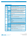
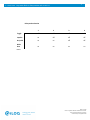
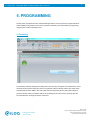
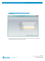
1 Käyttöohje USER MANUAL Key Switch R10S.3 Relay modules A00.11/A00.12 V. 1.1 26.2.2014 Operating, connection and programming manual iLOQ R10S.3, A00.11, A00.12 Made in Finland 1-Wire is registered trademark of Dallas Semiconductor. iLOQ is registered trademark of iLOQ Oy. ©2009 iLOQ Oy. All Rights Reserved V.1.0 4.2.2014 Key switch R10S.3, Relay modules A00.11/A00.12 2 CONTENTS 1. GENERAL 3 1.1 Relay modes 4 2. RELAY CONFIGURATIONS 5 2.1 Basic 2.2 1x2 2.3 1x8 2.4 2x8 2.5 1x16 5 6 6 7 7 3. OTHER CONNECTIONS 8 3.1 Roller door 3.2 Lock cylinder 8 8 4. INTERFACES 9 4.1 Key reader’s interfaces 4.1.1 Key reader’s A10.56 interfaces 4.1.2 Key reader’s A10.42 interface 4.2 Relay card’s interfaces 9 9 9 10 5. PROGRAMMING 12 5.1 Formatting 5.2 Adding and specifying a Key switch into the system 12 13 6. APPENDICES 20 Made in Finland 1-Wire is registered trademark of Dallas Semiconductor. iLOQ is registered trademark of iLOQ Oy. ©2009 iLOQ Oy. All Rights Reserved V.1.0 4.2.2014 3 Key switch R10S.3, Relay modules A00.11/A00.12 1. GENERAL The Key switch controls an electrical device with a potential-free relay output. The Relay outputs are activated when a valid key is inserted into the Key reader. The Key switch is formatted and programmed in the iLOQ S10 Manager software. The Key switch R10S.3 consists of two products: Relay card A00.10 and Key reader A10.56 or A10.42. This configuration may be expanded, if necessary, with the following components: Relay module A00.11 (8 outputs) 2x Relay module A00.11 (2x8 outputs) Relay module A00.12 (16 outputs) Lock cylinder C10/D10 Opening button Parallel Key reader A10.42 / A10.56 Real-time clock A00.9 In all configurations, the flush-mounted Key reader A10.42 can be used instead of the surface model Key reader A10.56. In that case, the LED indications will remain unconnected and the Key reader will be connected to the Relay card’s KEY READER connectors 1-WIRE (red) and GND (black). Key readers can also be connected 2 in parallel. Made in Finland 1-Wire is registered trademark of Dallas Semiconductor. iLOQ is registered trademark of iLOQ Oy. ©2009 iLOQ Oy. All Rights Reserved V.1.0 4.2.2014 4 Key switch R10S.3, Relay modules A00.11/A00.12 1.1 Relay modes The behaviour of the relay outputs, i.e. the Relay mode, is selected with the Relay card’s dip switch as per Table 1 or in the iLOQ S10 Manager software. The Relay mode selection in the key switch programming package overrides the Relay card dip switch selections 1-3, and in that case the dip switch positions 1-3 have no significance, but dip switch 4 must be in the correct position on the Relay card. Relay mode selection 1 2 3 4 Toggle off off off off Impulse on off off off Key hold on on off off Roller door on on on on Table 1 In Toggle mode, the relay output is activated with a valid key. The relay is activated until the next valid key is read. In Impulse mode, the relay output is activated for a certain time with a valid key. In Impulse mode, the default length for a K1 relay is 8 seconds and for a K2 relay 30 seconds. The default impulse of Relay module relays is 8 seconds long. The length of the impulses can be changed in the S10 Manager software. In Key hold mode, the relay output is active for as long as a valid key is in the Key reader. In Roller door mode, the relay outputs are activated with buttons when a valid key is in the Key reader. With this mode, a roller door, for example, can be controlled upwards or downwards using different buttons. Made in Finland 1-Wire is registered trademark of Dallas Semiconductor. iLOQ is registered trademark of iLOQ Oy. ©2009 iLOQ Oy. All Rights Reserved V.1.0 4.2.2014 5 Key switch R10S.3, Relay modules A00.11/A00.12 2. RELAY CONFIGURATIONS The relay configuration is selected in the S10 Manager software. The following relay configurations are available: Basic 1x2 1x8 2x8 1x16 More detailed descriptions of the functioning of the different configurations are given below. 2.1 Basic With the Relay card, 1-2 devices are controlled using relay outputs K1 and K2. Toggle, Impulse, Key hold and Roller door can be selected as the relay mode of the relays. In this configuration, a valid key always activates both relay outputs K1 and K2 (except in Roller door mode, which is a special connection, see section 3.1). Relay outputs can also be activated with a potential-free contact signal (e.g. with a push button) to input Button1. In that case, relays K1 and K2 will behave according to the selected relay mode in the same way as with a key. A practical example in Impulse mode with default delay times: A motorised lock is controlled with an 8 second impulse of the K1 relay, and the K2 relay is used to bypass the door’s magnetic switch for 30 seconds. When exiting this state, a push button is pressed, whereupon the motorised lock is opened and the door’s magnetic switch is bypassed for 30 seconds. Appendix 1: Wiring diagram R10S.3_Basic Made in Finland 1-Wire is registered trademark of Dallas Semiconductor. iLOQ is registered trademark of iLOQ Oy. ©2009 iLOQ Oy. All Rights Reserved V.1.0 4.2.2014 6 Key switch R10S.3, Relay modules A00.11/A00.12 2.2 1x2 With the Relay card, 1-2 devices are controlled using relay outputs K1 and K2. Toggle, Impulse, Key hold and Roller door can be selected as the relay mode of the relays. In this configuration, it is possible to specify for each access right which relay outputs a particular access right has the right to control. A valid key can therefore activate either both or only one of the relay outputs K1/K2. When the relay mode selection is Impulse, the length of the impulse is reset if a valid key is read in the Key reader again, even though the previous impulse is still active. In other words, the calculation of the delay starts from the beginning. Note. In this configuration, the button inputs BUTTON1 / BUTTON2 cannot be used. Appendix 2: Wiring diagram R10S.3_1x2 2.3 1x8 Relay module A00.11 is connected to the Relay card’s RS232-1 bus, whereupon 8 additional relay outputs can be used. A key can control 1-8 relay outputs of the Relay module simultaneously. Toggle, Impulse and Key hold can be selected as the relay mode of the relays. In Impulse mode, the default length of the Relay module’s impulse is 8 seconds. In this configuration, it is possible to specify for each access right which relay outputs a particular access right has the right to control. A valid key can therefore activate 1-8 relays of the Relay module. In addition, a valid key always activates both relay outputs K1 and K2 of the Relay card. When the relay mode selection is Impulse, and if a valid key is read in the Key reader again while the previous impulse is still active, the Relay module’s relays will be set according to the relay combination of the last valid key. In other words, if e.g. relay output 3 has been activated by key 1 when the control is still on, then key 2, which controls e.g. only relays 4 and 5, will be read. In that case, relay 3 will stop activating, whereupon only the relay combination of the last key, i.e. 4 and 5, will be activated. The Relay card’s relay outputs can also be activated with a potential-free contact signal (e.g. with a push button) to input Button1. In that case, relays K1 and K2 will behave according to the selected relay mode in the same way as with a key. The Relay module’s relays cannot be controlled with button input Button1. Appendix 3: Wiring diagram R10S.3_1x8 Made in Finland 1-Wire is registered trademark of Dallas Semiconductor. iLOQ is registered trademark of iLOQ Oy. ©2009 iLOQ Oy. All Rights Reserved V.1.0 4.2.2014 7 Key switch R10S.3, Relay modules A00.11/A00.12 2.4 2x8 Relay modules A00.11 are connected to the Relay card’s RS232-1 and RS232-2 buses, whereupon 16 additional relay outputs can be used. A key can control 1-16 relay outputs of the Relay module simultaneously. Toggle, Impulse and Key hold can be selected as the relay mode of the relays. In Impulse mode, the default length of the Relay modules’ impulse is 8 seconds. In this configuration, it is possible to specify for each access right which relay outputs a particular access right has the right to control. A valid key can therefore activate 1-16 relays of the Relay module. In addition, a valid key always activates both relay outputs K1 and K2 of the Relay card. When the relay mode selection is Impulse, and if a valid key is read in the Key reader again while the previous impulse is still active, the Relay module’s relays will be set according to the relay combination of the last valid key. In other words, if e.g. relay output 3 has been activated by key 1 when the control is still on, then key 2, which controls e.g. only relays 4 and 5, will be read. In that case, relay 3 will stop activating, whereupon only the relay combination of the last key, i.e. 4 and 5, will be activated. The Relay card’s relay outputs can also be activated with a potential-free contact signal (e.g. with a push button) to input Button1. In that case, relays K1 and K2 will behave according to the selected relay mode in the same way as with a valid key. The Relay modules’ relays cannot be controlled with button input Button1. Appendix 4: Wiring diagram R10S.3_2x8 2.5 1x16 Relay expansion A00.12 consists of Master and Slave Relay modules, both of which have 8 relay outputs. The Master is connected to the Relay card’s RS232-1 bus and the Slave is connected to the Master with a connecting cable. A key can control 1-16 relay outputs of the Relay module simultaneously. Toggle, Impulse and Key hold can be selected as the relay mode of the relays. In impulse mode, the default length of the Relay module’s impulse is 8 seconds. In this configuration, it is possible to specify for each access right which relay outputs a particular access right has the right to control. A valid key can therefore activate 1-16 relays of the Relay module. In addition, a valid key always activates both relay outputs K1 and K2 of the Relay card. When the relay mode selection is Impulse, and if a valid key is read in the Key reader again while the previous impulse is still active, the Relay module’s relays will be set according to the relay combination of the last valid key. In other words, if e.g. relay output 3 has been activated by key 1 when the control is still on, then key 2, which controls e.g. only relays 4 and 5, will be read. In that case, relay 3 will stop activating, whereupon only the relay combination of the last key, i.e. 4 and 5, will be activated. The Relay card’s relay outputs can also be activated with a potential-free contact signal (e.g. with a push button) to input Button1. In that case, relays K1 and K2 will behave according to the selected relay mode in the same way as with a key. The Relay module’s relays cannot be controlled with button input Button1. Made in Finland 1-Wire is registered trademark of Dallas Semiconductor. iLOQ is registered trademark of iLOQ Oy. ©2009 iLOQ Oy. All Rights Reserved V.1.0 4.2.2014 8 Key switch R10S.3, Relay modules A00.11/A00.12 Appendix 5: Wiring diagram R10S.3_1x16 3. OTHER CONNECTIONS 3.1 Roller door Via a Key switch, a roller door, for example, can be opened and closed using relay outputs K1 and K2. The relay mode of the relays, Roller door, is selected with dip switches. The control buttons of the door are connected to the Relay card using inputs Button1 and Button2. With a valid key in the Key reader, activation of input Button1 activates relay output K1 and activation of Button2 activates relay output K2. If both inputs Button1 and Button2 are activated at the same time, neither of the relay outputs K1 and K2 will be activated. Appendix 6: Wiring diagram R10S.3_Rollerdoor 3.2 Lock cylinder Relay K2 is controlled with a lock cylinder connected to the Relay card’s CYLINDER interface. Relay K2 is activated when a valid key is successfully read in the cylinder. A cylinder can be connected only in the Basic configuration and in the relay mode Impulse. The Relay card does not need to be programmed; relay K2 indicates a valid opening also in the factory state and in a formatted state. The cylinder to be connected can be an S10 or Privus, and an S10 cylinder does not need to be programmed in the same S10 system as the Relay card. The default impulse of the relay K2 is 30 seconds, and it can be changed in the S10 Manager software, but this requires the programming of the Relay card. If the Relay card is equipped with the Real-time clock A00.9 and formatted or programmed, the cylinder receives the time from the Relay card. Appendix 7: Wiring diagram R10S.3_Cylinder Made in Finland 1-Wire is registered trademark of Dallas Semiconductor. iLOQ is registered trademark of iLOQ Oy. ©2009 iLOQ Oy. All Rights Reserved V.1.0 4.2.2014 9 Key switch R10S.3, Relay modules A00.11/A00.12 4. INTERFACES 4.1 Key reader’s interfaces 4.1.1 Key reader’s A10.56 interfaces The Key reader is connected to the Relay card’s KEY READER connectors, whereupon a green light shows in the Key reader when the device is powered up (ONLINE LED). The key symbol indicates with a green and a red light whether the key inserted into the Key reader was approved or rejected (STAT1 G and STAT1 R). The Key reader also has inputs STAT2 GRN, STAT2 RED and GND for indications of the status of the device being controlled. To these inputs can be imported feedback information from the device being controlled in the form 3.3 – 24 VDC. If no feedback information is received from the device being controlled, the Relay card can also, if necessary, be connected to control the STAT2 GRN LED. In such cases, it should be noted that the STAT2 output will follow the Relay card’s relay output K1 status (except in Roller door mode). In cabling, a data transfer cable such as MHS 5x2x0.5 should be used. The maximum distance between the Relay card and the Key reader is 100 metres. 4.1.2 Key reader’s A10.42 interface The Key reader is connected to the Relay card’s KEY READER connectors 1-WIRE and GND such that the Key reader’s red wire is connected to 1-WIRE and black to GND. The Relay card also has a mating connector for the Key reader’s wire connector, which can be used, for example, in the commissioning-programming stage. In cabling, a data transfer cable such as MHS 2x2x0.5 should be used. The maximum distance between the Relay card and the Key reader is 100 metres. Made in Finland 1-Wire is registered trademark of Dallas Semiconductor. iLOQ is registered trademark of iLOQ Oy. ©2009 iLOQ Oy. All Rights Reserved V.1.0 4.2.2014 10 Key switch R10S.3, Relay modules A00.11/A00.12 4.2 Relay card’s interfaces Connector Place for real-time clock A00.9. Circuit board to be used unpowered and to be programmed after installation of the clock. REAL TIME CLOCK GND CYLINDER/ BUTTON2 MODE SELECT I0 4 3 2 1 GND BUTTON1 INPUT GND EXT IN GND NET BOX DATA GND 1-WIRE POWER ON KEY READER STAT1 G STAT1 R STAT2 G RELAY K2 STAT2 R GND NO NC COM RELAY K1 12…24VDC NO NC Input for lock cylinder or for potential-free point signal (e.g. opening button). Button activation controls relay K2 in Roller door mode. When the cylinder is connected, a valid opening activates relay K2. A cylinder can be used in the Basic configuration and in relay mode Impulse. Connected to cylinder’s yellowblack bus. 0 =yellow. GND=black. Dip switches are used to select the relay mode, i.e. the behaviour of relay outputs as per Table1. Dips 1-3 can be also be set by programming, in which case the positions of the dips on the Relay card are overwritten. Dip 4, however, must always be in the correct position on the Relay card. Input connector for potential-free point signal (e.g. button). Button activation controls relay K1 in Roller door mode when a valid key is in the Key reader. In Toggle, Impulse and Key hold modes, relay K1 is controlled as per the selected relay mode. Input connector for potential-free point signal. The input can be used to control a conditional access right. Open=access right blocked, closed=access right permitted. Connector for connecting to Network module. Connected to Network module’s corresponding lock interfaces GND and DATA. Ground 1-WIRE communication bus. Connected to corresponding connectors Key reader A10.56 or A10.42. A10.42: black=GND, red=1-WIRE Voltage output for controlling A10.56 ONLINE LED when Relay card is powered Voltage output for controlling Key reader A10.56 STAT1 G green LED when key is approved Voltage output for controlling Key reader A10.56 STAT1 R red LED when key is rejected Output voltage 3.3 VDC, follows status of relay K1. Can be connected for the control of the A10.56 STAT2 G green LED indicating the status of output K1. Not in use Ground Relay output K2 contacts. Output controlled, depending on relay configuration and relay mode, with a key, opening button BUTTON1 or BUTTON2 and lock cylinder. Output’s default impulse length is 30 seconds. COM Relay output K1 contacts. Output controlled, depending on relay configuration and relay mode, with a key or opening button BUTTON1. Output’s default impulse length is 8 seconds. CENTER PIN DC+ Plug connection for power supply. Plug dimensions 2.1/5.5 mm. On centre pin +. Voltage 12 – 24 VDC GND 12…48VDC Description DC+ Connector for power supply. Operating voltage 12 – 48 VDC Made in Finland 1-Wire is registered trademark of Dallas Semiconductor. iLOQ is registered trademark of iLOQ Oy. ©2009 iLOQ Oy. All Rights Reserved V.1.0 4.2.2014 11 Key switch R10S.3, Relay modules A00.11/A00.12 Relay mode selection 1 2 3 4 Toggle off off off off Impulse on off off off Key hold on on off off Roller door on on on on Table 1 Made in Finland 1-Wire is registered trademark of Dallas Semiconductor. iLOQ is registered trademark of iLOQ Oy. ©2009 iLOQ Oy. All Rights Reserved V.1.0 4.2.2014 12 Key switch R10S.3, Relay modules A00.11/A00.12 5. PROGRAMMING The Key switch is programmed in the iLOQ S10 Manager software. If the Key switch is programmed before actual installation, Key reader A10.42 can be connected to the Relay card for the duration of programming, using the quick connector intended for this. 5.1 Formatting Format the Key switch by adding the formatting task to the Token by pressing the Format state button. Follow the wizard and insert the Programming device’s programming cable into the Key switch’s Key reader, when formatting task has been added to the Token. Wait until the Programming device’s status light changes to green and the Key switch is formatted. Remove the formatting task from the Token by pressing again the Format state button, following the wizard’s instructions. Made in Finland 1-Wire is registered trademark of Dallas Semiconductor. iLOQ is registered trademark of iLOQ Oy. ©2009 iLOQ Oy. All Rights Reserved V.1.0 4.2.2014 13 Key switch R10S.3, Relay modules A00.11/A00.12 5.2 Adding and specifying a Key switch into the system 5.2.1 Click Add lock 5.2.2 Specify Placement and Locking target. Select type R10S.3.x to Lock cylinder -field. Specify whether or not a real-time clock will be used, as well as the Lock type. Made in Finland 1-Wire is registered trademark of Dallas Semiconductor. iLOQ is registered trademark of iLOQ Oy. ©2009 iLOQ Oy. All Rights Reserved V.1.0 4.2.2014 14 Key switch R10S.3, Relay modules A00.11/A00.12 5.2.3 Select relay configuration 5.2.4 If the relay configuration is 1x2, 1x8 , 2x8 or 1x16 specify which relay outputs are in use and name the outputs Made in Finland 1-Wire is registered trademark of Dallas Semiconductor. iLOQ is registered trademark of iLOQ Oy. ©2009 iLOQ Oy. All Rights Reserved V.1.0 4.2.2014 15 Key switch R10S.3, Relay modules A00.11/A00.12 5.2.5 Select the relay mode 5.2.6 If Impulse has been selected as the relay mode, you can specify the length of the relays’ impulse in seconds. Made in Finland 1-Wire is registered trademark of Dallas Semiconductor. iLOQ is registered trademark of iLOQ Oy. ©2009 iLOQ Oy. All Rights Reserved V.1.0 4.2.2014 Key switch R10S.3, Relay modules A00.11/A00.12 16 5.2.7 Complete, if you wish, other optional information Made in Finland 1-Wire is registered trademark of Dallas Semiconductor. iLOQ is registered trademark of iLOQ Oy. ©2009 iLOQ Oy. All Rights Reserved V.1.0 4.2.2014 Key switch R10S.3, Relay modules A00.11/A00.12 17 5.2.8 Select access rights for the Key switch 5.2.9 Specify which outputs each access right can control Made in Finland 1-Wire is registered trademark of Dallas Semiconductor. iLOQ is registered trademark of iLOQ Oy. ©2009 iLOQ Oy. All Rights Reserved V.1.0 4.2.2014 18 Key switch R10S.3, Relay modules A00.11/A00.12 5.2.10 Select the number of Key switches to be created 5.2.11 Select Order and transfer programming tasks to programming device 5.2.12 Insert the Programming device’s programming cable into the Key reader and wait until the Status light changes to green Made in Finland 1-Wire is registered trademark of Dallas Semiconductor. iLOQ is registered trademark of iLOQ Oy. ©2009 iLOQ Oy. All Rights Reserved V.1.0 4.2.2014 Key switch R10S.3, Relay modules A00.11/A00.12 19 The product is covered by a 24 month guarantee from the date of commissioning. A decommissioned product can be restored to the factory state and used again or it can be disposed of as electronic scrap. Made in Finland 1-Wire is registered trademark of Dallas Semiconductor. iLOQ is registered trademark of iLOQ Oy. ©2009 iLOQ Oy. All Rights Reserved Mode Toggle Impulse Key hold 1 off on on Dip switch position 2 3 off off off off on off Relay mode selection 4 off off off Optional A00.9 RTC A00.10 A00.10 Button1 activates relays K1 and K2 Optional: 1 Black Red K1 Status output 3,3 VDC Optional A10.42 Status input of controlled device 3,3..24 VDC GND 3,3..24 VDC GND DC IN 12...48 VDC 35717 Wiring diagram R10S.3_Basic Separate ground Valid key insertion into the reader (A10.56/A10.42) activates relays K1 and K2 MHS 5x2x0,5 Max. 100m A10.56 V.1.0 4.2.2014 Key switch R10S.3, Relay modules A00.11/A00.12 20 Appendix 1: Wiring diagram R10S.3_Basic 6. Appendices Made in Finland 1-Wire is registered trademark of Dallas Semiconductor. iLOQ is registered trademark of iLOQ Oy. ©2009 iLOQ Oy. All Rights Reserved Mode Toggle Impulse Key hold 1 off on on Dip switch position 2 3 off off off off on off Relay mode selection 4 off off off Optional A00.9 RTC A00.10 A00.10 1 Black Red K1 Status output 3,3 VDC Optional A10.42 Status input of controlled device 3,3..24 VDC GND 3,3..24 VDC GND DC IN 12...48 VDC 35717 Wiring diagram R10S.3_1X2 Separate ground Valid key insertion into the reader (A10.56/A10.42) activates relays K1 and/or K2 MHS 5x2x0,5 Max. 100m A10.56 V.1.0 4.2.2014 Key switch R10S.3, Relay modules A00.11/A00.12 21 Appendix 2: Wiring diagram R10S.3_1x12 Made in Finland 1-Wire is registered trademark of Dallas Semiconductor. iLOQ is registered trademark of iLOQ Oy. ©2009 iLOQ Oy. All Rights Reserved 1 2 3 4 5 6 7 8 NO C NC NO C NC NO C NC NO C NC NO C NC NO C NC NO C NC NO C NC Mode Toggle Impulse Key hold 1 off on on A00.11 Dip switch position 2 3 off off off off on off Relay mode selection 4 off off off Optional A00.9 RTC A00.10 A00.10 1 Black Red K1 Status output 3,3 VDC Optional A10.42 3,3..24 VDC GND 3,3..24 VDC 35717 Wiring diagram R10S.3+A00.11_1x8 Separate ground Status input of controlled device GND DC IN 12...48 VDC MHS 5x2x0,5 Max. 100m A10.56 V.1.0 4.2.2014 Key switch R10S.3, Relay modules A00.11/A00.12 22 Appendix 3: Wiring diagram R10S.3+A00.11_1x8 Made in Finland 1-Wire is registered trademark of Dallas Semiconductor. iLOQ is registered trademark of iLOQ Oy. ©2009 iLOQ Oy. All Rights Reserved 1 2 3 4 5 6 7 8 NO C NC NO C NC NO C NC NO C NC NO C NC NO C NC NO C NC NO C NC Mode Toggle Impulse Key hold 1 off on on A00.11 Dip switch position 2 3 off off off off on off Relay mode selection 4 off off off Optional A00.9 RTC A00.10 A00.10 1 Black Red K1 Status output 3,3 VDC Optional A10.42 3,3..24 VDC GND 3,3..24 VDC A00.11 35717 8 7 6 5 4 3 2 1 Wiring diagram R10S.3+A00.11_2x8 Separate ground Status input of controlled device GND DC IN 12...48 VDC MHS 5x2x0,5 Max. 100m A10.56 NC C NO NC C NO NC C NO NC C NO NC C NO NC C NO NC C NO NC C NO V.1.0 4.2.2014 Key switch R10S.3, Relay modules A00.11/A00.12 23 Appendix 4: Wiring diagram R10S.3+A00.11_2x8 Made in Finland 1-Wire is registered trademark of Dallas Semiconductor. iLOQ is registered trademark of iLOQ Oy. ©2009 iLOQ Oy. All Rights Reserved 1 2 3 4 5 6 7 8 NO C NC NO C NC NO C NC NO C NC NO C NC NO C NC NO C NC NO C NC Mode Toggle Impulse Key hold A00.12 Master A00.12 Slave 1 off on on Dip switch position 2 3 off off off off on off Relay mode selection 4 off off off Optional A00.9 RTC A00.10 A00.10 1 Black Red K1 Status output 3,3 VDC Optional A10.42 3,3..24 VDC GND 3,3..24 VDC 35717 Wiring diagram R10S.3+A00.12_1x16 Separate ground Status input of controlled device GND DC IN 12...48 VDC MHS 5x2x0,5 Max. 100m A10.56 V.1.0 4.2.2014 Key switch R10S.3, Relay modules A00.11/A00.12 24 Appendix 5: Wiring diagram R10S.3+A00.12_1x16 Made in Finland 1-Wire is registered trademark of Dallas Semiconductor. iLOQ is registered trademark of iLOQ Oy. ©2009 iLOQ Oy. All Rights Reserved Mode Roller door 1 on Dip switch position 2 3 on on Relay mode selection Buttons 1&2 operate only with a valid key 4 on Optional A00.9 RTC Button2 controls relay K2 A00.10 A00.10 Button1 controls relay K1 1 Black Red Optional A10.42 GND DC IN 12...48 VDC MHS 5x2x0,5 Max. 100m 35717 Wiring diagram R10S.3_Rollerdoor A10.56 V.1.0 4.2.2014 Key switch R10S.3, Relay modules A00.11/A00.12 25 Appendix 6: Wiring diagram R10S.3_Rollerdoor Made in Finland 1-Wire is registered trademark of Dallas Semiconductor. iLOQ is registered trademark of iLOQ Oy. ©2009 iLOQ Oy. All Rights Reserved or Mode Impulse Yellow Optional A00.9 RTC MHS 2x2x0,5 max. 200m A10.34 A00.10 1 on Dip switch position 2 3 off off 4 off A00.10 Relay mode selection Black Valid key insertion into a cylinder activates relay K2 C10S/P D10S/P Button1 activates relays K1 and K2 Optional: 1 Black Red K1 Status output 3,3 VDC Optional A10.42 Status input of controlled device 3,3..24 VDC GND 3,3..24 VDC GND DC IN 12...48 VDC 35717 Wiring diagram R10S.3_Cylinder Separate ground Valid key insertion into the reader (A10.56/A10.42) activates relays K1 and K2 MHS 5x2x0,5 Max. 100m A10.56 V.1.0 4.2.2014 Key switch R10S.3, Relay modules A00.11/A00.12 26 Appendix 7: Wiring diagram R10S.3_Cylinder Made in Finland 1-Wire is registered trademark of Dallas Semiconductor. iLOQ is registered trademark of iLOQ Oy. ©2009 iLOQ Oy. All Rights Reserved