1
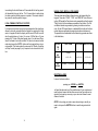
Installer Notes:
Elite 16D Version
16 Zone Controller
6
Arrowhead
Alarm Products Ltd
Operating Guide
Please contact your alarm installer if you require further information.
20
1
Proudly Designed and Manufactured in New Zealand
CONTENTS
OWNERS DETAILS
Page No.
NAME:
INTRODUCTION
3
About your Alarm
3
OPERATING YOUR ALARM
ADDRESS:
4
General Information
Arming the Alarm
Disarming the Alarm
Arming in Stay Mode
Disarming Stay Mode
Bypassing Zones
Manual Panic, Medical & Fire Alarms
Resetting Alarms
4
4
4
5
5
6
7
7
TELEPHONE NUMBER:
INSTALLERS NAME:
PROGRAMMING YOUR ALARM
Getting into Program Mode
Exiting Program Mode
Adding or Deleting User Codes
Changing Telephone Numbers
Programming the Time & Date
8
8
8
8
9
9
SPECIAL CONTROL BUTTON FUNCTIONS
Directly Controlling Outputs from the Keypad
Disable Day (Chime) Mode Alarms
Operating the Access Control Output
10
10
11
12
REMOTE COMMAND CONTROL OPERATION
How Remote Command Control works
Local Command Control of outputs
INSTALLERS CONTACT PH #:
12
12
14
USER FUNCTIONS
15
15
MEMORY DISPLAY MODE
16
Viewing Memory Mode
Current System Alarms
Historical Event Display Chart
OWNERS DETAILS
Code 3
Code 6
Code 9
Code 12
Code 15
PANEL TELEPHONE NUMBERS:
PH # 2
PH # 1
PH # 4
PH # 5
PH # 3
PH # 6
ZONE DESCRIPTIONS:
15
Starting Walk-test Mode
Answer an In-coming Call
ACCESS CODES:
Code 1
Code 2
Code 4
Code 5
Code 7
Code 8
Code 10
Code 11
Code 13
Code 14
16
16
17
Zone # 1
Zone # 3
Zone # 5
Zone # 7
Zone # 9
Zone # 11
Zone # 13
Zone # 15
Zone # 2
Zone # 4
Zone # 6
Zone # 8
Zone # 10
Zone # 12
Zone # 14
Zone # 16
19
2
19
INTRODUCTION
HISTORICAL EVENT DISPLAY CHART-Continued
EVENT
DEVICE
INDICATOR
STATUS
ABOUT YOUR ALARM
KEYPAD PANIC
Panic Alarm at Keypad
LINE
LED’s 1-8
Flashing
Flashing
Thank you for choosing to protect your premises with the Elite 16D
(PW16). In doing so you have invested in the most advanced and
adaptable panel on the market.
KEYPAD FIRE
Fire Alarm at Keypad
LINE
CONTROL
Flashing
Flashing
KEYPAD MEDICAL
Medical Alarm at Keypad
LINE
BYPASS
Flashing
Flashing
ARMED
Area "A" Armed
"A"
On Steady
ARMED
Area "B" Armed
"B"
On Steady
ARMED
Area "C" Armed
“C”
On Steady
STAY MODE ON
Area "A" in Stay Mode
"A"
Flashing
STAY MODE ON
Area "B" in Stay Mode
"B"
Flashing
STAY MODE ON
Area "C" in Stay Mode
“C”
Flashing
TELEPHONE LINE FAIL
Panel Dialler
LINE
On Steady
EXCESSIVE RE-TRIES
Panel Dialler
LINE
LED 1
On Steady
On Steady
FAILURE TO GET A
KISSOFF
Panel Dialler
LINE
LED 2
On Steady
On Steady
WALKTEST MODE
Manual Walk-test
Mode
MAINS
BATTERY
LINE
LED’s 1-16
On Steady
On Steady
On Steady
On Steady
18
3 Separate Alarm Panels: Your Elite 16D can operate as three totally independent alarms. These independent ‘AREAS’ can be controlled from
one global keypad or from multiple keypads assigned to specific areas.
The Elite 16D has many incredible program options and additional accessories that can enhance the standard features of the panel offering simple
“Home Automation” to “Radio control” and “Voice Prompted
Command Control”. Please check with your installer to find out more
about these powerful features.
The Elite 16D can communicate with monitoring stations or call you at
work,on your cell phone or your pager to warn of intruders.
You can phone your home to check or change the status of any output
using the keys on your phone.
Arm or disarm the whole house or just one area, all with your own voice
confirming your selections.
Imagine turning on the spa before leaving work so it is hot when you get in
the door. The under-floor heating has just automatically switched on using
the on board timer and you have just opened the rollerdoor and disarmed
the garage from your cell phone so the white ware repairman can work on
your washer.
The controller will support a 16 LED keypad or the more sophisticated
LCD (liquid Crystal Display) keypad.
It also has a comprehensive alarm event memory that stores all of the
controller activity with the time and date. The event memory is accessible
from both keypads but the time & date information can only be displayed
via the LCD keypad.
3
OPERATING YOUR ALARM
GENERAL INFORMATION
Your PW16 Alarm Controller has been designed with you the user in mind.
Clearly named backlit keys mean you don't have to remember complicated
key combinations to achieve a result. As with everything about the PW16
even key functions can be fine tuned to your specific needs. Please ask
your installer.
ARMING THE ALARM
Arming the alarm will turn on all detectors in the Area or Areas being
Armed. To Arm the alarm press;
<ARM>
Area A,B or C armed LED’s will turn ON or
<CODE><ENTER>
Area A,B or C armed LED’s will turn ON or
<ARM><CODE><ENTER>
Area A,B or C armed LED’s will turn ON.
The panel has three different Arming modes and the methods of Arming
are detailed above. The installer will advise you on how they have configured your particular alarm.
HISTORICAL EVENT DISPLAY CHART
EVENT
DEVICE
INDICATOR
STATUS
ACTIVATION
Zones 1-16
LED's 1-16
On Steady
BYPASS
Zones 1-16
BYPASS
LED's 1-16
On Steady
On Steady
DETECTOR TAMPER
(SHORT CIRCUIT)
Zones 1-8
TAMPER
LED's 1-8
Flashing
On Steady
DETECTOR TAMPER
(OPEN CIRCUIT)
Zones 9-16
TAMPER
LED's 9-16
Flashing
On Steady
CABINET TAMPER
Cabinet or Satellite
Siren
TAMPER
Flashing
WRONG CODE ALARM
Code Tamper at
Keypad #
TAMPER
LED’s 1-8
On Steady
On Steady
CROW KEYPAD TAMPER
SWITCH ACTIVATED
Keypad Tamper Alarm
at Keypad #
TAMPER
LED’s 1-8
On Steady
On Steady
LOW BATTERY
Controller Battery
BATTERY
Flashing
MAINS FAILURE
Controller Mains Supply
MAINS
Flashing
FUSE FAILURE (F1 or F2)
Controller on-board
fuses
MAINS
Flashing
LOW BATTERY-ZONE
Radio Zone
Zone 1-16
BATTERY
LED's 1-16
Flashing
On Steady
LOW BATTERY-PENDANT
Radio Key
User 1-20
BATTERY
LED's
1-16,
17,18,19,20
Flashing
On Steady
ZONE INACTIVITY
TIMEOUT
Zone 1-16
LED’s 1-16
TAMPER
CONTROL
On Steady
Flashing
Flashing
SUPERVISED RADIO
TIMEOUT
Zone 1-16
LED’s 1-16
TAMPER
BYPASS
On Steady
Flashing
Flashing
DURESS ALARM
Duress Alarm
(at Keypad #)
TAMPER
LINE
LED’s 1-8
Flashing
Flashing
On Steady
DISARMING THE ALARM
Disarming the alarm will turn off all detectors in the Area or Areas that
were Armed. To Disarm the alarm press;
<CODE><ENTER>
Area A,B or C armed LED’s will turn OFF.
There is also a special feature that can be set by your installer to allow the
pressing of the <ARM> button during the Exit Delay time to Disarm the
alarm. This feature is to allow a quick disarm if you have forgotten to do
something prior to Arming the alarm. The feature is disabled when the
alarm is fully armed following expiry of the exit delay time.
4
17
MEMORY DISPLAY MODE
VIEW MEMORY MODE
This alarm panel has an event memory which stores the most recent
events, (up to 255), including all alarm events, all system events such as
mains failure etc as well as arming by Area. This event memory is displayed via the standard keypad with the most recent event shown first and
subsequent events following in descending order from newest to oldest.
The "MEMORY" light will flash when there is a new event in memory
which has not been viewed. To stop the "MEMORY" light flashing, simply
press the <MEMORY> button and the events will be flashed back to you
with the most recent event shown first.
Note: To stop the memory display function press “ENTER”. Each event is
separated by a beep tone. The memory light will also stop flashing when
the system is armed.
CURRENT SYSTEM ALARMS
When viewing the memory event buffer at the keypad by pressing the
<MEMORY> button, the first thing that will always be displayed are the
Current System Alarms that are still present. The Current System Alarms
are indicated by the Memory/Mains & Battery LEDS being on plus a zone
LED from 1-8 to indicate the system alarm/s present. If no Zone LED’s are
on at this time, it means that there are no current system alarms. If a zone
LED or LED’s are On then this indicates system alarms that have not yet
cleared. The zone LED’s 1-8 are pre-defined as to what system alarm they
will display. These system alarm indications are shown in the table below.
Following the display of current system alarms the panel will then sequence through the 255 historical memory events starting at the most recent event. The second table shows the alarm events that can be displayed in memory mode and what indicators are used to show them
CURRENT SYSTEM ALARMS
LED #1
Battery Low
LED #5
Radio Pendant Battery Low
LED #2
Mains or 12V Fuse Failure
LED #6
Supervised Detector Failure
LED #3
Telephone Line Failure
LED #7
Zone Inactivity Timeout
LED #4
Radio Detector Battery Low
LED #8
Dialler Kiss-off Failure
16
ARMING IN STAY MODE
Stay mode allows you to Arm a pre-selected part of the building. Stay
mode can be used in a residential application to arm parts of the house
that you will not need to go into at night time or in a commercial application
to allow monitoring of an unattended shop front. The Stay mode alarm can
be in the form of a full alarm or possibly a small buzzer (Chime) to warn of
activity in the stay mode coverage area. To arm Stay mode press;
<STAY>
Area A,B or C armed LED’s will FLASH or
<STAY><CODE><ENTER>
Area A,B or C armed LED’s will FLASH.
The panel has two different Stay arming modes and the methods of Arming are detailed above. The installer will advise you on how they have configured your particular alarm.
Once Stay mode has been Armed, the normal exit delay will apply and if a
zone is triggered the normal entry delays will also apply. If, however you
press the <ENTER> button following Arming of Stay mode, this will cancel
the exit delay so the system is armed immediately and also cancel ALL
entry delay times so all zones will become Instant alarm zones. This allows you to select whether you wish the Stay Mode to Arm with or without
delays every time you arm this mode.
DISARMING STAY MODE
Disarming Stay Mode will turn off all Stay Mode detectors in the Area or
Areas that were Armed. To Disarm Stay Mode press;
<STAY>
Area A,B or C armed LED’s will turn OFF or
<CODE><ENTER>
Area A,B or C armed LED’s will turn OFF.
The single button disarm of stay mode indicated above is a programmable
option so you will need to check with your installer how your system has
been configured.
5
BYPASSING ZONES
USER FUNCTIONS
This key allows you to temporarily by-pass zones of your choice prior to
arming your panel. The bypassed zones will go back to normal the next
time you disarm the panel. A typical example would be if you wanted to let
your pet run around in the garage when your system is armed, you could
choose to bypass that detector (say Zone 1) from the system.
To bypass zone 1, key in the following sequence:
<BYPASS>
Bypass LED will turn ON.
<01>
Zone 1 LED will turn ON.
<ENTER>
Bypass LED will now FLASH.
While in the Bypass mode it is possible to Bypass more than one zone.
The example below details how this is done.
To exclude zones 1,9 & 16, key in the following sequence:
<BYPASS>
Bypass LED will turn ON.
<01,09,16>
Zone LED’s 1,9 & 16 will turn ON.
<ENTER>
Bypass LED will now FLASH.
NOTE: Zones and keypads can be assigned to one or all of the three
possible Areas available in the Elite 16D. If you are trying to
Bypass a zone that is in an Area NOT assigned to your keypad, the
panel will not allow you to bypass that zone.
If you are using an LCD keypad to Bypass zones, the Bypass button
works the same as the LED keypad but the display shows the numbers as
entered e.g. in the example above as you enter in the digits “01”, the display will show “01”, then if you enter “09”, the display will show “01” & “09”
on the display and finally as you enter “16” the display will show all three
numbers on the screen. The LCD keypad will show up to 5 two digit numbers then if you need to bypass more zones it will alternate the display
with the first 5 selections then the next 5, switching between displays at
about a 1 second rate.
6
STARTING WALKTEST MODE
While in CLIENT mode a User with the proper authority can start walk-test
mode. This special mode latches the alarm signals from detectors at the
keypad initiating the test so that one person can trigger every detector
connected to the alarm then return to the keypad to verify operation. On
terminating Walk-test mode the test results are put into the memory buffer
so they can be viewed at a later time.
To start Walk-test mode while in CLIENT mode press;
<PROGRAM> <836> <ENTER>
The keypad buzzer will beep at 1 second intervals
Next trigger every detector connected to the panel then return to the keypad and all of the zones that were triggered will be displayed at the keypad.
To terminate Walk-test mode press;
<ENTER>
The keypad will stop beeping and automatically exit CLIENT mode.
ANSWER AN IN-COMING CALL
From time to time your installer may need to access the alarm from a remote PC to make changes to your programming and for security reasons
they may have configured the alarm so that an authorised person on-site
is required to make the alarm system answer the in-coming call. This option is only available in CLIENT mode.
To answer an In-coming Call press;
<PROGRAM> <835> <ENTER>
Provided the line connected to the alarm was ringing at the time the panel
will now answer the call and allow a remote PC connection.
15
is monitoring the line at all times and 15 seconds after the last key press it
will automatically hang up the line. This 15 second timer is active during
the whole command control process so a period of 15 seconds without a
key press will cause the panel to hang-up.
LOCAL COMMAND CONTROL OF OUTPUTS
If a command control code for outputs is programmed and the output/s are
allowed to be locally controlled from the keypad, then entering the 4 digit
code at a keypad will blank the display and the zone LED’s will now indicate the output status e.g. if output 1 is on zone 1 LED will be on. By now
pressing the “1” button at the panel keypad, output 1 can be turned off provided it is allowed to be locally controlled. To leave local command control
mode simply press the <ENTER> button and the keypad will return to normal operation. This feature works the same way that “Directly Controlling
an Output” works (see page 8) only it requires a code to access the function.
MANUAL PANIC, MEDICAL & FIRE ALARMS
There are three special Manual Alarms that may be triggered from the
keypads. These are a “PANIC” , “FIRE”, and “MEDICAL” alarm. When using the LED keypad the Panic alarm can be generated by either the single
“Panic” button or by the simultaneous operation of two buttons. The Fire
and Medical alarms are generated by pressing two buttons simultaneously. On the LCD keypad there is no dedicated Panic button so the three
manual alarms are generated by pressing two buttons simultaneously.
The special button combinations and the alarms they generate are shown
in the table below;
KEYPAD
TYPE
È
PANIC ALARM
FIRE ALARM
MEDICAL ALARM
<1> & <3>
<4> & <6>
<7> & <9>
<CHIME> & <CONTROL>
<A> & <B>
<B> & <CHIME>
<PANIC>
LED
KEYPAD
LCD
KEYPAD
RESETTING ALARMS
In case of an alarm condition,
pressing your <CODE> then <ENTER>
will reset the alarm and turn off any audible sirens. If your code does not
reset the alarm it means that the alarm occurred in an Area either not assigned to the keypad you are using or your code is not allowed to reset
alarms in that area.
NOTE: If at any stage you make an error when entering a code all you
need to do is press the <ENTER> button to reset the keypad and start
again.
14
7
PROGRAMMING YOUR ALARM
GETTING INTO PROGRAM MODE
There are 2 levels of program mode, CLIENT mode and INSTALLER
mode. Normally the installer will give you access to the CLIENT mode so
you can add, delete, or change the user codes. If you request it your installer can provide you with access to the INSTALLER mode as well.
In CLIENT mode you can program up to 50 individual User Codes that
may be from 1-6 digits in length. Each of the 50 Users can be assigned
NO access, LIMITED access or FULL access to CLIENT mode. The limited access can be taylored by the installer whereas full access allows the
User to display and change all access codes, change the panel time &
date, answer an in-coming call for remote PC access, print the event
buffer to a serial printer and initiate Walk-test mode. All of these things can
be explained in detail by your installer.
To get into CLIENT mode provided the system is NOT armed press;
<PROGRAM> <CODE> <ENTER>
Program LED with turn ON
If you get a single long beep at this point and the Program LED doesn’t
turn on, it means your code cannot access Program mode.
EXITING PROGRAM MODE
To exit out of program mode press;
<PROGRAM> <ENTER>
Program LED will turn Off
ADDING OR DELETING A USER CODE
Once in CLIENT mode, to program a User code you enter the User code
address (a value from 1-50) then the new code. For example to program
User # 3 with a code “2580”, key in the following sequence:
modem tone and then again pause for 5 seconds looking for your access
code. This process will be repeated 4 times before hanging up if no valid
code is received. When entering codes or other information in Command
Control the "#" key acts as a "Clear" button.
When you have entered the required 4 digit access code the panel will reply with the status message associated with the Command Control function you have accessed. For example, lets say we have a code of “2045”
to allow Arming & Disarming of Area A. Once the code “2045” has been
received the panel checks the current status of Area A and replies with the
pre-programmed voice message relating to that status e.g. if Area A is
Armed then the Armed message will be sent, if Disarmed then the Disarmed message will be sent. If only the DTMF board is fitted, the voice
message is substituted with a long beep if Area A is Armed, and three
short beeps if it is disarmed.
Once the status message has informed you of the actual state, you can
use the "*" key to toggle the option on & off or Arm and Disarm, e.g. in our
example above, code “2045” accesses Area "A" arming or disarming.
Assuming the status message we received was "Area A alarm is Armed"
If we press the "*" key, Area "A" will be Disarmed and we would receive a
status message "Area A alarm is Disarmed" (or whatever message is programmed by the installer)
While you are on-line with the panel you can move between menu options
by entering the code of the option you want to control. Assuming there
was a code of “4321” programmed to control outputs. After having used
code “2045” to control the Arm/Disarm status of Area A we first press the
“#” button to reset all previous entries. Then we can enter the digits
“43215” (that is “4321” as the code to control outputs and “5” to select output #5). The current status of output #5 will be given either by the voice
message or the appropriate tone and then the status can be changed with
the “*” button on the remote telephone (Note; For output control you must
enter in the 4 digit code e.g. 4321 followed by the output number you wish
to control, in this case 5).
At any stage, if you enter in an incorrect code you can press the “#” button
on the remote telephone to clear all code entries and then start again.
<PROGRAM> <3> <ENTER> <2580> <ENTER>
(If there is an existing code already at that address it will be flashed back
on the key pad display. Entering the new code will delete the old and the
new code will be flashed back to you).
To turn on the optional Microphone (only available if the Voice Board is
fitted) you must enter in the appropriate code followed by the “*” button. To
turn the Microphone off you simply press the “*” button again.
To end a Command Control session simply hang up the phone. The panel
8
13
OPERATING THE ACCES CONTROL OUTPUT
If the alarm system has been set up to allow control of an electric door
lock, you can activate the door release function as follows;
The panel will give 3 short beeps to indicate correct entry or 1 long tone if
not accepted.
To remove or clear a user code number 1234 from user 3, key in the
following sequence
<CONTROL> or
<CONTROL> <CODE> <ENTER>
The Control LED on the LED keypad will turn on while the lock is active
and turn off as soon as power is removed from the lock.
The Access Control function can either be a single button operation or restricted to requiring a valid User code entry. Both options are shown
above. Please consult your installer as to what option may be programmed.
REMOTE COMMAND CONTROL OPERATION
HOW REMOTE COMMAND CONTROL WORKS
Another powerful feature available from your alarm is Command Control.
This feature is a remote control facility which allows valid users to access
the panel via a standard touch tone telephone and check or change the
Arm/Disarm status of each of the areas, operate each of the eight outputs
or turn on an optional Microphone.
The Command Control feature is only available on panels fitted with a
Voice or DTMF board. The Voice board provides voice prompts to guide
you through Command control operations whereas the DTMF board provides tones (one Long Tone for ON or three short beeps for OFF).
Please talk to your installer to find out if all or any of these options are
available on your alarm.
To perform any of the Command Control features you must first ring the
phone number which the panel is connected to. The panel may be set up
to answer after a specific number of rings of it may be set-up to use a fax
defeat option. Either way, when you ring the phone number and the panel
answers the call, the first thing you will hear over the phone is a burst of
modem tone for two seconds. After this tone has stopped you must enter
the access code which is associated with the Command menu option you
wish to access. Remember, the code you enter will determine which
menu option you access. If you miss the pause, the panel will repeat the
12
<PROGRAM> 3 <ENTER><BYPASS><ENTER>(LED Keypad)
<PROGRAM> 3 <ENTER><CONTROL> then 0 <ENTER>(LCD Keypad)
Address 1 = User # 1, 2 = User# 2 to 50 = User# 50.
(Note: on the LED keypad “0” is indicated by LED “A” and “9” by LED “B”)
CHANGING TELEPHONE NUMBERS
Your panel will accept up to 6 phone numbers with a total of 16 digits.
Your panel can be can be programmed to dial all or any of these
depending on the event which has occurred.
(The six phone numbers are at program addresses 331 through to 336)
While in CLIENT mode, key in the following sequence:
<PROGRAM> <331> <ENTER>
(the address for telephone number 1)
The existing number will be flashed out at the keypad then enter;
<NEW TELEPHONE #> <ENTER>
The new numbers will be flashed back to confirm acceptance.
At any time you can enter in the address for the telephone number just to
view the currently programmed value then press the <PROGRAM> button
to move on to another address.
Address 331 = PH # 1, 332 = PH# 2 to 336 = PH# 6.
Note: on the LED keypad “0” is indicated by LED “A” and “9” by LED “B”
PROGRAMMING THE TIME & DATE
The alarm system has an internal clock that may be used to automatically
Arm or Disarm the alarm or turn Outputs On or Off. It is also used to identify when events occurred in memory via the LCD keypad. Should you
need to change the Time & Date it must be done from CLIENT mode.
9
To change the Time & Date press;
<PROGRAM> <823> <ENTER> <1-7> <ENTER>
Where 1-7 = the current day (1=Sun, 2 = Mon to 7 = Sat)
<PROGRAM> <824> <ENTER> <HHMM> <ENTER>
Where HH = Hour in 24 Hour Format and MM = Minutes
keypad indicating that it has been turned on. Pressing the same number
again will turn the output number being displayed off, indicating the output
is now off.
When finished, press the <ENTER> button to exit the direct output control
mode.
DISABLE DAY (CHIME) MODE ALARMS
<PROGRAM> <825> <ENTER> <1-31> <ENTER>
Where 1-31 = the current date
<PROGRAM> <826> <ENTER> <1-12> <ENTER>
Where 1-12 = the current month
<PROGRAM> <827> <ENTER> <YY> <ENTER>
Where YY = current year, e.g. 02=2002
SPECIAL CONTROL BUTTON FUNCTIONS
The <CONTROL> button on the keypad has a number of uses depending
on the options set by your installer.
It can be used to disable Day-zone alarms (Chime), directly control any of
the outputs from the keypad or operate a door for access control.
The operation of the various <CONTROL> button functions (if enabled by
the installer) are detailed below;
DIRECTLY CONTROLLING an OUTPUT
To directly control outputs from the LED or LCD keypads press;
<CONTROL>
(Note: The LCD Control Button must be held for 2 seconds)
The control LED will turn on at the LED keypad, the LCD display will show
OUTPUTS
__
__
__
__
__
__
__
__
Any detector on your Elite can be programmed to trigger a buzzer or
chime at your keypad/s when movement is detected. These are called Day
(Chime) Zones. They can be programmed into the system by your installer. Your installer can also give you the ability to disable the Day
(Chime) Zone monitoring via the keypad when it is not required.
To Disable the Day (Chime) Zone Monitoring at an LED keypad press;
<CONTROL> <PROGRAM>
The control LED will turn on to indicate the disable function is active
To re-enable the Day (Chime) Zone monitoring press;
<CONTROL> <PROGRAM>
The control LED will turn off to indicate the Day (Chime) zones are active
To Disable the Day (Chime) Zone Monitoring at an LCD keypad press;
<CHIME>
The LCD display will read “CHIME OFF”
The Display will timeout after 20 seconds back to the normal display or
you can press the <ENTER> button to go back to the normal display.
To re-enable the Day (Chime) Zone Monitoring at an LCD keypad press;
<CHIME>
The LCD display will read “CHIME ON”
The Display will timeout after 20 seconds back to the normal display or
you can press the <ENTER> button to go back to the normal display.
Now by pressing any of the buttons from 1-8 (your installer has to allow
the outputs to be directly controlled otherwise you cannot turn them On or
Off at this point), the appropriate output number will be displayed at either
10
11