1
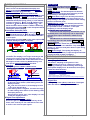
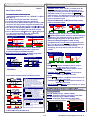
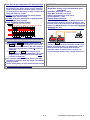
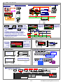
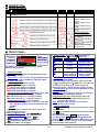
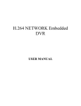
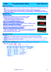
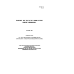
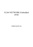
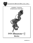
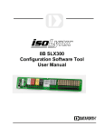
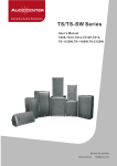
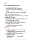
CS2-TM(Pulse Input) TOTALIZER / BATCH / IMMEDIATE VALUE (for Flowmeter or Lengh/RPM) CONTROLLER USER MANUAL ■ DESCRIPTION The CS2-TM(Pulse Input) is innovation totalizer. Adtek builds in high technology with wide input range from 0.01Hz~ 140.00KHz with auto-range function at same unit. There are three setting modes for K factor, 1/K factor and flow speed to match the difference output description of flowmeters. The Totalizer provides high accuracy measurement, display, control and communication (Modbus RTU mode) of Pulse from flowmeter or encoder, approach switch, photo switch for length control. There are two display screen and 3 external control input (DI) in standard and the optional 4 Relay, 1 Analogue, 1 Pulse and RS485 port available. They are also support fantastic control function as like as N, C, R mode for totalizer and batch control. ■ FEATUTRES ● Measuring Pulse AUTO RANGE 0.01Hz~100KHz(optional:140KHz); Contact / NPN / PNP / Voltage Pulse can be switch on rear of meter ● ● ● ● ● ● Dual display screen for 10 digital Totalizer or Batch counter + 4 2/3 Immediate Value(PV) or 6 digital Batch programmable. 4 relay can be individual programmed to relative immediate value, totalizer or batch. Relative to Immediate Value(PV): Functions settable Energized Mode Hi / Lo / Hi(Lo) Hold / Do / Go, Hysteresys‚ Energized Delay, De-energized Delay, Energized latch or Energized by RS485 command. Relative to Totalizer / Batch: N/C/R mode and energized time programmable. 3 external control input can be individual programmed for immediate value(PV) or totalizer / batch. Immediate Value(PV): PV Hold / Reset for Maximum or Minimum Hold / DI / Reset for Relay Energized Latch Totalizer / Batch: Reset, Gate Analogue Output and Pulse Output available in option RS485(Modbus RTU mode), Baud Rate is up to 38400bps Comply to CE standard FUNCTIONS ■ Input & Scaling Input Range The meter has been designed very wide input range from 0.01Hz~100.00KHz(Option: 0.01Hz~140.00KHz) that can cover almost any application for flowmeter. User doesn’t need to specify the input range. Three setting modes for flowmeters There are three types setting for Pulse/Flow-unit(K factor), Flow/Pulse(1/K factor) and Flow rate/Hz to match the difference output description of flowmeters. Engineer needs just to check the mode of flowmeter and setting. The totalizer will calculating the flow rate, and accumulation. 1Pulse/Flow-unit(K factor): The decimal point of K Factor: Setting range from 0.0 to 0.0000. Pulse/Flow-unit(K factor): Setting range from 0.0001 to 9999.9 Flow/Pulse (1/K factor): The decimal point of 1/K Factor: Setting range from 0.0 to 0.0000. Flow/Pulse(1/K factor): Setting range from 0.0001 to 9999.9 Valume/Hz: The decimal point of pipe’s diameter: Setting range from 0.0 to 0.0000. Diameter of pipe: Setting range from 0.0 to 0.0000M The decimal point of flow speed (Lengh/sec): Setting range from 0.0 to 0.0000. Flow Speed: Setting range from 0.0001 to 9999.9M 1 / 27 CS2-TM(Pulse)-Operating Manual 2012-05-10 Auto Range: ■ DISPLAY FUNCTIONS Dual Display screens Down screen can be Immediate Value(PV) and Batch programmable; Up screen can be Totalizer and Batch counter programmable. Maximum Hold or Minimum Hold for PV When the DSPLY function in【Input Group】set to be MAX.H(Max. Hold) or Mini.H(Mini. Hold), The meter will keep display in maximum (or minimum) value of Immediate Value(PV) during power on, until manual reset by front key in 【User Level】, Up/Down Key function or【External Control Input(E.C.I.)】; The Reset functions will be explan in detail in following. Please paste the sticker M.H on the red square LED to identify the status of display. Immediate Value(PV) Hold Three mode selectable between Auto(Auto range)/SEMi(Semi-Auto range)/MANUL(Manual range) Auto(Auto range): The decimal point will be auto changed according to the input frequency so that keep reading in the highest resolution. SEMi(Semi-Auto range): The decimal point will be auto changed according to the input frequency to keep reading in the highest resolution under setting position of decimal point. MANUL(Manual range): The decimal point will be fixed according to the setting of decimal point. So, it’s possible to show “overflow”, if the input frequency is over the display range. Time out at Lowest frequency In the case of low frequency, the totalizer can not to identify that is low frequency and no input until the next pulse input. Sometimes, it takes a long period. CS2-TM builds in a time out function to cut out the reading. There are two modes MAnAL / AUto can be selected. When the External Control input set to be Pv. HLd(PV Hold) function in【ECI Gruop】, The display will be hold, when the E.C.I. is closed until the E.C.I. is to be open. Please paste the sticker PV.H on the green square LED of ECI to identify the status of display. Max. ( Mini.) Hold & Reset PV Hold & Reset Maximum Hold Present Value Reset the Max.(or Mini.) Hold by E.C.I. or Front Key Level Trigger ON Reset Data Hold by E.C.I. PV Hold Present Value ON ON Level ON Trigger Write to display by RS485 command The display can be written by RS485 command. At meantime, the display is no longer according to the input signal. In past, The meter normally receive 4~20mA or 0~10V from AO card or BCD card of PLC. We support a new solution by RS485 writing in so that can be save cost and wiring into PLC. display “0”, when the next pulse doesn’t input during the setting time. Auto(Auto range): The reading will display “0”, when the next pulse doesn’t input during the time that gave by formular of meter’s firmware. ■ READING STABLE FUNCTIONS Average Display update Setting range: 1~99 times; The meter’s sampling is 15cycle/sec. If the AvG(Average) set to be 3, it means the meter is sampling 3 readings, and calculating the average then update display once. At meantime, the display update will be 5 times/sec. Low Cut Setting range from -29999~+29999 counts. Low Cut set to be +0.50 Present Value Low Cut set to be -0.10 PV according to input signal Present Value PV according to input signal Average set to be 3 Sample 1 0.50 Low cut function Low cut function Low Cut is set for 0.50, if the PV is from -0.50~+0.50, that display will be 0. Sample 2 Sample 3 Sample 4 Sample 5 Sample 6 ……. Display Update Value = Display Update Value = (Sample 1 + Sample 2 + Sample 3)/3 (Sample 1 + Sample 2 + Sample 3)/3 -0.10 -0.50 MANUL(Manual): There is a period named ito can be set from 0.0 sec~999.9sec. The reading will Remark: The higher average setting will cause the response time of Relay and Analogue output slower. Low Cut is set for -0.10, if the PV is under (<= -0.10), that display will be -0.10. If the setting value is positive, it means the range of absolute value will be 0; PV≤ Setting value, the display will be 0; Ex:Low Cut is set for 0.10, if the display is from -0.10~+0.10, that will be 0. If the setting value is negative, it means the range of under setting value will be 0; PV≤ -Setting value, the display will be 0; Ex:Low Cut is set for -0.01, if the display is ≤ -0.01, and all the display will be 0. Digital filter Setting range from 0(None)/1~99 times. The digital filter can reduce the magnetic noise in field. Digital Fine Adjustment Setting range from -19999~+29999 ; Users can get Fine Adjustment by front key of the meter, and “Just Key In” the value which user want to show in the current input signals. 2 / 27 CS2-TM(Pulse)-Operating Manual 2012-05-10 ■ RELAY FUNCTIONS Multi-Cross Function selection ■ 3 External Control Inputs(E.C.I.) For Immediate Value(PV) 4 relay can be programmable to relative Totalizer, Batch, Batch Counter and Immediate Value(PV) with individual functions. Relative to Immediate Value(PV) Relay energized mode Hi / Lo / Hi.HLd / Lo.HLd / DO/ Go-1.2 Hi: Relay will energize when PV > Set-Point Lo: Relay will energize when PV < Set-Point Hi.HLd (Lo.HLd): When the PV Higher (or lower) than set-point, the relay will be energized and hold until manual reset by from key in【User Level】or【E.C.I.】. DO: Relay is energized by RS485 command directly, and no longer to compare with set-point of relay Go-1.2: Go function with 【Set-Point 1】and【Set-point 2】. Go relay energized when the condition is set-point 1(Hi) > PV > set-point 2(Lo) Hi / Lo / Go Relay Energized Hi(Lo) Energized Hold & Reset Hi Setting Hi Setting Lo Setting Hi RL Energized Hi.HLd(High Hold) Relay Energized ON ON Lo RL Energized ON Go RL Energized ON ON Reset the relay Hold by ECI or Front Key Level T rigger ON Hysteresis: Settable range from 0~9999 Counts Relay energized delay: Settable range from Inhibit ON De-energized delay time Relay Energized Energized delay time Start Band Start Delay Time Set Point Totalizer ON Auto Reset Totalizer Relay output Time Relay Output Set Point ON Auto Reset Totalizer Relay output Time Relay Output Level Trigger ON Reset Data Hold by E.C.I. ON ON Level ON Trigger DI(Digital Input): The E.C.I can be set to be DI(Digital Input) function, when the meter building in RS485 port. The computer is easier to get a switch status through the meter as like as DI of PLC. Reset for Relay Energized Latch: If relay energized mode was set to be Energized hold, the E.C.I. can be set to be rY.rSt(Reset Relay function). When the PV meets the condition of relay energizing, the relay will be hold until the E.C.I. is closed. Reset for Energy / Batch Energy Energy / Batch Level Trigger Gate by E.C.I. or Front Key Hysteresis Energy / Batch N MODE: When the condition of Set Point is met: 1. the relay will be energized; 2. The totalizer will run as same as usual; until manual reset by front key or by rear terminal, the totalizer will be reseted to “0” and the relay will be de-energized. R MODE: When the condition of Set Point is met: 1. The relay will be energized; until the time is over Relay output time rY.1(2).ot(Relay1(2) output time). 2. The totalizer will run as same as usual; until the time is over Relay output time rY.1(2).ot(Relay1(2) output time),The totalizer will be reset to “0”. C MODE: When the condition of Set Point is met: 1. The relay will be energized; until the time is over Relay output time rY.1.ot or rY.2.ot . 2. The totalizer will be reset to “0”, then counts-up from “0”. ON O N ON ON Edge Trigger Reset by E.C.I. or Front Key O N ON ON Gate ON Gate GAtE: Totalizer and Batch will be stop to Batch Gate bt.GtE: Batch will be stop to count, Totalizer Gate tL.GtE: Totalizer will be stop to count, when E.C.I. Iis close. The 3 mode are very useful idea to control the totalizer and batch. The relay energized condition is according to not only energized level, but also time and reset for totalizer, batch and batch counter. Relay Output Reset the Max.(or Mini.) Hold by E.C.I. or Front Key PV Hold Present Value Gate for Energy / Batch Energy Relative to Totalizer / Batch / Batch Counter N/C/R Mode Manual Reset PV Hold & Reset Maximum Hold Present Value Hi Setting Inhibit Set Point Max. ( Mini.) Hold & Reset Energized / De-energized Delay & Hysteresis Hi Setting Relay Energized Rel.Pv(Relative PV) function. When the E.C.I. is closed, the reading will show the differential value. PV Hold: The E.C.I. can be set to be Pv.HLd(PV Hold) function. The display will be hold when the E.C.I. is closed, until the E.C.I. is to be open. Please refer to the below figure. Reset for Maximum or Minimum Hold: Please refer to the below figure. For Totalizer / Batch) 0.1(second)~9(minutes)59.9(seconds); Relay de-energized delay: Settable range from 0.1(second)~9(minutes)59.9(seconds) Start Delay Relative PV or Tare: The E.C.I. can be set to be when E.C.I. Iis close. count, when E.C.I. Iis close. Reset Reset rESEt: Totalizer and Batch will be reset to “0”, Totalizer Reset tL.rSt: Totalizer will be reset to “0”, when E.C.I. Iis close. when E.C.I. Iis close. Batch Reset bt.rSt: Batch will be reset to “0”, when E.C.I. Iis close. ■ ANALOGUE OUTPUT FUNCTIONS Relative to immediate value(PV), totalizer, batch or batch count programmable. Ao.LS: Setting range: -19999~+29999; Analogue Output Low relative Low Scale Ao.HS: Setting range: -19999~+29999; Analogue Output relative High Scale SCALE Default: Ai.Lo: 0%, Ai.Hi: 100%; Lo.SC: 0.00, Hi.SC: 100.00 Change to Ai.Lo: 0%, Ai.Hi: 75%; Lo.SC: 0.00, Hi.SC: 199.99 199.99 SCALE Setted Scaling: Lo.SC: 0.00, Hi.SC: 199.99; Desired Output: Ao.Lo: 50.00(PV), Ao.Hi: 150.00(PV) 199.99 150.00 100.00 100.00 ON 50.00 Period of Relay on: 0:00.0~9(Minutes):59.9(Second) 0.00 0.00% 3 / 27 INPUT 50.00% 75.00% 100.00% 0.00 0.00% OUTPUT 50.00% 100.00% CS2-TM(Pulse)-Operating Manual 2012-05-10 Fine Zero & Span Adjustment for Analog Output: Users can get Fine Adjustment of analogue output by front key of the meter. Please connect standard meter to the terminal of analogue output. To press the front key(up or down key) of meter to adjust and check the meter the output. Ao.Zro: Fine Zero Adjustment for Analog Output; Setting range: -38011~27524; Ao.Spn: Fine Span Adjustment for Analog Output; Setting range: -38011~27524; ■ RS485 Communication Protocol: ModBus RTU Mode Baud Rate: Setting range:1200/2400/4800/ 9600/ 19200/38400 Data Bits: Selectable 7 or 8 bits Stop Bits: Selectable 1 or 2 bits Parity: Selectable Even / Odd / None Divice Number: 1~255 Remote Display function High Limited for Analog Output SCALE Setted Scaling: Lo.SC: 0.00, Hi.SC: 199.99; Desired Output: Ao.Lo: 50.00(PV), Ao.Hi: 150.00(PV); Ao.LMt: 80.00% 199.99 150.00 Ao.LMt: 80.00%(=130.00) The display can be written by RS485 command. In past, the meter normally receive 4~20mA or 0~10V from AO card or BCD card of PLC. We support a new solution by RS485 writing in so that can be save cost and wiring into PLC. CS2 APPLICATION FOR RS485 WRINTING IN 100.00 RS 485 Modbus RTU Mode (up to 38400bps) RS485 wiring 1.2KM maximum Terminate Resistor: 50.00 0.00 0.00% OUTPUT 50.00% 100.00% RL1 RL2 com ECI ■ Pulse Output Relative to Totalizer, batch or batch counter Pulse dividerPLS.dv: Settable range from 1~9999. PLS.dv set to be 1: It will output 1 pulse, when totalizer increases “1Count”. Ex: It will output 1 pulse, when totalizer from 12345.678 increse to 12345.679, PLS.dv set to be 1000: It will output 1 pulse, when totalizer increases “1000Count”. Ex: It will output 1 pulse, when totalizer from 12345.678 increase to 12346.678. The maximum output is 1000Hz. Please sets lower resolution of totalizer, when the output over 1000Hz. Duty Cycle: 50% Please specify Relay or Open Collect output in order RL1 RL2 com ECI When the diPLY(Display Function) set to be RS485, it means, the PV screen will show the number from RS485 command & data. The data(number) will be same as PV that will compare with set-point, analogue output and ECI functions so that is to control analogue output, relay energized and so on. ■ OEM function is welcome 4 / 27 CS2-TM(Pulse)-Operating Manual 2012-05-10 ■ APPLICATIONS CS2-TM & CS2-PR APPLICATION FOR FLOWNETER / PRESSURE MEASURING Flowmeter Controller - RS485 communication Batch Control RS 485 Modbus RTU Mode (up to 38400bps) Analog Output 0~10V/0(4)~20mA AO AL Pulse AL AL 4 Relay Output for PV: Mode: High or Low Energized / Energized Hold / DO Functions: Start delay / Energized & De-energized delay / Hysteresis 4 Relay Output for Totalizer / Batch: RS 485 R L 1 R L 2 R L 3 RL 4 CI11 CI2 CI3 COM RL2 ECI1 R L3 ECI2 R L4 ▲ ENT/FN R L 1 RL 2 RL3 R L 4 EC1 EC2 EC3 Mode: N / C / R Mode COM RL1 L/min ▼ Display: ECI3 ◄ ENT/FN ▲ Mode: Measuring Value / Maximum Hold / Minimum Hold / Reading value from RS485 command Kg/ ▼ COM 3 External Control Input: ENT/FN ▲ Functions: Relative PV / PV Hold / Reset Max or Mini. Hold / DI / Reset for Relay Energized Hold Application: Thermal Switch / Circuit Breaker / Push Button / …… ▲ L/min ▼ mVdc信號輸出 電流分流器 流量計(Flowmeter) Measuring Input 2 For batch control. Ex. Package Machine for Beer, UP.dSP set to be Bt.Cnt , and dSPLY for down screen set to be bAtCH , Relay 1 energized mode set to be btCH.C , and set-point is 750mL. Relay 2 energized mode set to be totL.C , and set-point is 24. The Batch counter will count 1 and relay 1 energized when batch increase to 750mL. It mens finishing 1 bottle beer. When Batch counter in up screen increase to 24, the relay 2 energized to pack one box. RL1 R L 2 RL3 RL4 ENT/FN Set P o in t Relay status Indication Up screen for Totalizer Operation Key ENT/FN CI2 CI3 Up Screen for Batch Counter Down screen for Batch COM A u to R eset ? ENT/FN CI11 CI2 CI3 Up Screen for Batch Counter Down screen for Batch COM mL ? B a tc h R e la y o u tp u t T im e ON B a tc h 1 2 24 B a tc h Count 1 ■ INSTALLATION RL2 RL3 RL4 ? CI11 CI2 CI3 Control Input status Comm. status COM ? ENT/ Down screen for PV or Batch Engineer Unit L/min ? R L R L R L R L CI CI CO L/min ? FIX HOLDER: 104 mm(L) / W M3 PANEL CUT-OUT: 92+0.2(W) x 44+0.2(H) mm ■ DIMENSIONS 1.0~8.0 mm ■ WIRING DIAGRAM Relay 1 FRONT VIEW RL1 R L 2 RL3 RL4 mL ? R e la y O u tp u t ■ FRONT PANEL RL1 ? CI11 a 48.0 Relay 3 Relay 2 c b c a b c Relay 4 RS 485 Analogue output port a a A c 21 22 23 24 25 26 27 28 29 30 31 32 33 34 100.0 8.0 Terminal blocks: 10A/300Vac, M2.6, M2.6, 1.3~2.0mm2 (16~22AWG) If the pulse output is to be selected, the meter can be selected 3 relay maximum(without Relay 4). Pulse Output 96.0 B 12.0 ECI1 ECI2 ECI3 COM 0V Unit: mm +V 44.0+0.2 +IN PANEL CUT-OUT 11 12 13 14 15 Dimensions: 96mm x 48mm x 120mm Panel Cutout: 93mm x 45mm (advise) Pulse/Freq. SIGNAL INPUT 92.0+0.2 D-S 3 Dip-Switch D-S 1 2 3 4 5 NPN ON PNP ON M.C. ON ON 5VP 12VP ON 24VP ON D-S is on, when it is on down side. 4 5 6 External Control Input 7 8 9 10 AC115V AC230V AC 86~265V FG ADH DC 100~300V ADL DC 20~56V AUX. POWER ■ ORDERING INFORMATION ■ ORDERING INFORMATION Input Relay Output CS2−TM− Signal − − OPTION 2 Analogue Output − OPTION 3 RS 485 Port − OPTION 5 Pulse Output − Aux. Powered − *Optional Customize function is welcome. Please Function contact with our sales window for detail. OPTION 1 CODE C 00 N P V 05 12 24 I/P RANGE Contact NPN PNP Voltage Pulse 5V pulse 12V pulse 24V pulse CODE N R2 R3 R4 RELAY O/P None 2 Relay 3 Relay 4 Relay* * If the pulse output is to be selected, the meter can be selected 3 relay maximum. CODE ANALOG O/P None N V 0(1) ~ 5 V 0 ~ 10 V I 0 ~ 10 mA 0(4)~20 mA 5 / 27 CODE RS485 PORT None N 8 RS 485 CODE PULSE O/P None N Open Collect C R Relay Contact CODE AXU. POWER A AC115/230V OPTION 4 ADH ADL AC 85~265V DC100~300V DC 20~56 V CS2-TM(Pulse)-Operating Manual 2012-05-10 ■ OPERATION: ■ ERORR MASSAGE STEP DESCRIPTION DISPLAY FLASH REMARK BEFORE POWER ON, PLEASE CHECK THE SPECIFICATION AND CONNECTION AGAIN. SELF-DIAGNOSIS AND ERROR CODE: (Please check the input signal) (Please check the input signal) (Please check the input signal) (Please check the input signal) (Please send back to manufactory for repaired) (Please process Calibrating Input Signal) (Please check Calibrating Input Signal) (Please process Calibrating Output Signal) (Please check Calibrating Output Signal) : Display is positive-overflow (Signal is over display range) : Display is negative-overflow (Signal is under display range) : ADC is positive-overflow (Signal is higher than input 120%) : ADC is negative-overflow (Signal is lower than input -120%) / : EEPROM occurs error / : Calibrating Input Signal do not process / : Calibrating Input Signal error / : Calibrating Output Signal do not process / : Calibrating Output Signal error ■ FRONT PANEL: Relay status Indication Up screen for Totalizer Operation Key RL1 R L2 RL3 RL4 ENT/FN CI11 CI2 CI3 Operating Key: 4 keys for Enter(Function) / Shift(Escape) / Up key / Down key Setting Status Function Index Increase Go back to previous Up key number function index Decrease Go to next Down key number function index Go back to this Shift key Shift the setting position function index, and abort the setting Setting From the function Enter/Fun Confirmed and index to get into key save to EEProm setting status Control Input status Comm. status COM L/min Down screen for PV or Batch Engineer Unit CS2-TM has two display screens and I/O status indication for purposes. Numeric Screens Up screen: 0.28”(0.71cm) red high-brightness LED for 10 digital totalizer. Down screen: 0.28”(0.71cm) red high-brightness LED for Immediate Value 4 2/3 digital or Batch 6 digital. I/O Status Indication Relay Energized: 4 square red LED RL1 display when Relay 1 energized; RL2 display when Relay 2 energized; RL3 display when Relay 3 energized; RL4 display when Relay 4 energized; External Control Input Energized: 3 square green LED ECI1 display when E.C.I. 1 close(dry contact) ECI2 display when E.C.I. 2 close(dry contact) ECI3 display when E.C.I. 3 close(dry contact) RS485 Communication: 1 square red LED COM will flash when the meter is receive or send data, and COM flash quickly means the data transient quicker. Stickers: Pass Word: Setting range:0000~9999; User has to key in the right pass word so that get into【Programming Level】. Otherwise, the meter will go back to measuring page. If user forget the password, please contact with the service window. Function Lock: There are 4 levels selectable for lock. None: no lock all. User Level: User level lock. User can get into user Programming Level: Programming level lock. level for checking but setting. User can get into programming level for checking but setting. ALL: All lock. User can get into all level for checking but setting. Front Key Function The Key can be set to be the same function as the setting of ECI1. The Key can be set to be the same function as the setting of ECI2. Ex. The ECI1 set to be Pv.HLd and the function E.1=UP set to be YES in【ECI Group】. When user presses Key, the PV will hold as like as ECI1 close. If the front key function has been set, the terminal input for ECI will be disabling. Each meter has a sticker what are functions and engineer label enclosure. Relay energized mode: H H H i L o L L D O E.C.I. functions mode: PV.H(PV Hold) / Tare / DI / M.RS(Maximum or Minimum Reset) / R.RS(Reset fo Relay Latch) Engineer Label: over 80 types. 6 / 27 CS2-TM(Pulse)-Operating Manual 2012-05-10 ■ OPERATING DIAGRAM: USER LEVEL USER LEVEL 0−8 M.rSt: Reset for Maximum & Minimum storage CS2-tM: Model munber PLS1.0: firmware version Cyclic to first page ▲ ▼ ▲ ▲ ▼ 0−0−1 0−4 0−5 0−0−2 0−9 ▲ 0−1 ▲ ▼ This page will show out, when pulse output was to specify in order. rY4.SP: Relay 4 Set-point setting This page will not show out, when the relay mode was to be set N/R/C mode rY.rSt: Reset for energized latch of Relay Min: PV Minimum storage ▼ ▲ ▼ ▲ This page will show out, when PV is to be set. bAtCH: Batch rY1.SP: Relay 1 Set-point setting ▼ MEASURING PAGE Press 1sec. ▼ model number and firmware version This page will show out, when dSPLY set to be bAtCH . Pv : Present Value(Immedia te Value) ▲ Batch for 1 second can back to Measuring Page ▼ ▲ ▼ Self-diagnosis (LED All bright) Totalizer 0−0−1 Press 0−6 Power on ENT rY2.SP: Relay 2 Set-point setting ▲ ▼ 0−3 ▲ NO rY3.SP: Relay 3 Set-point setting ▼ ENT ▲ ▼ Enter the password to get into Programming Level Press to enter & setting MAX: PV Maximum storage 0−7 1sec. 0−2 Press Correct? PROGRAMMING LEVEL YES Default =1000 Press for 1 second to back Measuring Page ▼ ▲ ENT ENT ▲ ▼ C−1 B−1 B−2 C−2 7 / 27 ▲ ▲ Next Page ECi.1: External Control Input 1 nonE rEL.Pv Pv.HLd M.rSt rY.rSt di GAtE rESET tL.GtE tL.rSt bt.GtE bt.rSt ECi.2: External Control Input 2 nonE rEL.Pv Pv.HLd M.rSt rY.rSt di GAtE rESET tL.GtE tL.rSt bt.GtE bt.rSt ENT ▼ A−2 ▲ ▼ ▲ Next Page rY.Sd: Start delay time for Relay energized 0:00.0~ 9(M):59.9(S) ▼ ▲ The defference mode selected will show up relative parameters F.tYP: Modes description of Flowmeter PLS/F F/PLS d.MUL.v rY.Sb: Start band for Relay energized ▼ ▲ ▼ Next Page Pv.bSE: Time unit of Immediate Value(PV) 1/SEC 1/Min 1/Hour 1/dAY ▼ ▲ ▼ A−1 ENT D−1 GROUP D−2 GROUP ANALOGUE OUTPUT GROUP EXTERNAL CONTROL INPUT GROUP ▲ RELAY ▼ INPUT Ao.SEL: Analogue output relative parameter Totalizer/Batch /PV selection Pv bAtCH totAL Ao.tYP: Analogue Output type v.0~10 v.0-5 v.1-5 A.0-10 A.0-20 A.4-20 Next Page CS2-TM(Pulse)-Operating Manual 2012-05-10 D−3 D−4 D−5 D−7 D−6 C−3 C−4 C−5 C−6 D−8 Ao.LS: Analogue Output relative Low Scale Immediate Value(PV): -19999~+29999 Totalizer/Batch: 0~9999999999 Ao.HS: Analogue Output relative High Scale Immediate Value(PV): -19999~+29999 Totalizer/Batch: 0~9999999999 Ao.Zro: Fine Zero Adjustment for Analog Output Immediate Value(PV): -38011~+27524 Totalizer/Batch: 0~9999999999 Ao.SPn: Fine Span Adjustment for Analog Output Immediate Value(PV): -38011~+27524 Totalizer/Batch: 0~9999999999 Z.S.CLr: Clear Fine Zero / Span Adjustment for Analog Output nonE Ao.Zro Ao.SPn both Ao.LMt: Analog Output High Limit -0.00~110.00% of FS RS485 GROUP ENT Next Page ▲ ▼ ▲ ▼ ▲ ▼ The page will show out, when rY2.Md set to be Hi/Lo mode. rY2.rd: Relay 2 energized delay time 0:00.0~ 9(M):59.9(S) E−1 B−3 B−4−0 B−4 A−3−1−1 A−3−1−2 A−3−2−1 A−3−2−2 B−5 B−6 B−7 B−8−0 B−8 ▲ ▲ B−9 ▲ A−3−3−1 ▲ A−3−3−2 ▲ ▲ ▼ ▲ A−3−3−3 ▲ ▼ ▲ A−3−3−4 ▲ ▲ E.2=dn: E.C.I.2=Down; Down key will be same function as E.C.I.2 set. YES no ▼ ▲ E.1=UP: E.C.I.1=UP; Up key will be same function as E.C.I.1 set. YES no ▼ dEbnc: Debouncing of external control Input 5~255( x 8ms) ▼ ECi.3: External Control Input 3 nonE rEL.Pv Pv.HLd M.rSt rY.rSt di GAtE rESET tL.GtE tL.rSt bt.GtE bt.rSt ▼ ▲ ▼ ▲ A−4 ▲ ▼ ▲ ▼ ▲ ▼ The page will show out, when rY1.Md set to be Hi/Lo mode. rY1.rd: Relay 1 energized delay time 0:00.0~ 9(M):59.9(S) The page will show out, when rY1.Md set to be Hi/Lo mode. rY1.Fd: Relay 1 de-energized delay time 0:00.0~ 9(M):59.9(S) rY2.Md: Relay 2 energized mode oFF Lo Hi Hi.HLd Lo.HLd do btcH.n btcH.r btcH.C totL.n totL.r totL.C The page will show out, when rY2.Md set to be N/R/C mode. rY2.ot: Relay 2 energized time 0:00.0~ 9(M):59.9(S) The page will show out, when rY2.Md set to be Hi/Lo mode. rY2.HY: Relay 2 Hysteresis 0~5000 counts ▼ ▲ rY1.Md: Relay 1 energized mode oFF Lo Hi Hi.HLd Lo.HLd do btcH.n btcH.r btcH.C totL.n totL.r totL.C The page will show out, when rY1.Md set to be N/R/C mode. rY1.ot: Relay 1 energized time 0:00.0~ 9(M):59.9(S) The page will show out, when rY1.Md set to be Hi/Lo mode. rY1.HY: Relay 1 Hysteresis 0~5000 counts ▼ ▲ ▼ ▲ ▼ ▼ ▲ ▼ The page will show out, when d.MUL.v is to be set. vL.dP: Decimal Point of Flow speed (Lengh/sec) 0~0.0000 The page will show out, when d.MUL.v is to be set. vL/ Hz: Valume/Hz, Flow speed setting 0.0000~999.99 SP.dP: Decimal point of set-point for Realy energized 0~0.0000 ▼ ▲ ▼ The page will show out, when d.MUL.v is to be set. diAMt: Diameter of pipe setting 0.0000~999.99M ▼ ▲ ▼ The page will show out, when d.MUL.v is to be set. diA.dP: Decimal Point of diameter of pipe 0~0.0000 ▼ ▲ ▼ The page will show out, when F/PLS is to be set. F/P.dP: Decimal Point of Flow/P (1/K Factor) 0~0.0000 F/PLS: Flow/Pulse (1/K Factor) Setting 0.0000~999.99 ▼ ▲ ▼ PLS/F: P/Flow(unit) (K Factor) Setting 0.0000~999.99 ▼ ▲ ▼ Next Page The page will show out, when PLS/F is to be set. P/F.dP: Decimal Point of P/Flow(unit) (K Factor) 0~0.0000 AdrEs: Device number of the meter 1~255 Next Page 8 / 27 CS2-TM(Pulse)-Operating Manual 2012-05-10 E−2 E−3 B−10 B−11 B−12−0 B−12 B−13 B−14 B−15 B−16−0 A−5 A−6 A−7 ▲ A−8 ▲ A−9 ▲ A−10 ▲ A−11 ▲ ▲ ▲ A−12 ▲ bAUd: Baud rate 1200 2400 4800 9600 19200 38400 PritY: Parity n.Stb.1 n.Stb.2 odd EvEn ▼ ▲ ▲ ▼ The page will show out, when rY2.Md set to be Hi/Lo mode. rY2.Fd: Relay 2 de-energized delay time 0:00.0~ 9(M):59.9(S) rY3.Md: Relay 3 energized mode oFF Lo Hi Hi.HLd Go-1.2 Lo.HLd do btcH.n btcH.r btcH.C totL.n totL.r totL.C The page will show out, when rY3.Md set to be N/R/C mode. rY3.ot: Relay 3 energized time 0:00.0~ 9(M):59.9(S) The page will show out, when rY3.Md set to be Hi/Lo mode. rY3.HY: Relay 3 Hysteresis 0~5000 counts The page will show out, when rY3.Md set to be Hi/Lo mode. rY3.rd: Relay 3 energized delay time 0:00.0~ 9(M):59.9(S) The page will show out, when rY3.Md set to be Hi/Lo mode. rY3.Fd: Relay 3 de-energized delay time 0:00.0~ 9(M):59.9(S) The page will not show out, when pulse output has been specified. rY4.Md: Relay 4 energized mode oFF Lo Hi Hi.HLd Lo.HLd do btcH.n btcH.r btcH.C totL.n totL.r totL.C The page will show out, when rY4.Md set to be N/R/C mode. rY4.ot: Relay 4 energized time 0:00.0~ 9(M):59.9(S) ▼ ▲ ▼ ▼ ▼ Next Page Lo.Cut: Low Cut -29999~+29999 ▼ ▲ dSPLY: Display Function for down screen Pv Mini.H MAX.H RS485 bAtCH ▼ S.CLr: Clear Fine Span Adjustment for Immediate Value(PV) display ▼ Adjustment for Immediate Value(PV) display ▲ ▼ ▲ 100.00 Pv.SPn: Fine Span ▼ ▲ ▼ SiGn: Sign of accumulate up or down PStvE dUAL ▼ ▲ ▼ oFL.Md: overflow mode of totalizer or batch ovFL rCYCL ▼ ▲ ▼ UP.dSP: Up screen displays totalizer or batch Counter noMAL Bt.Cnt ▼ ▲ ▼ ttL.dP: Decimal point of totalizer 0~0.0000 Next Page 9 / 27 CS2-TM(Pulse)-Operating Manual 2012-05-10 B−16 B−17 B−18 A−13 A−14 A−15 ▲ ▲ A−16 ▲ ▼ ▲ ▼ rAnGE: Input range AUto SEMi MAnUL ▼ ▲ ▼ The page will show out, when ito.Md set to be MAnUL . Ito: The time of time out ▼ ▲ ▼ ito.Md: Input Time Out Mode AUto MAnUL The page will show out, when rY4.Md set to be Hi/Lo mode. rY4.HY: Relay 4 Hysteresis 0~5000 counts The page will show out, when rY4.Md set to be Hi/Lo mode. rY4.rd: Relay 4 energized delay time 0:00.0~ 9(M):59.9(S) The page will show out, when rY4.Md set to be Hi/Lo mode. rY4.Fd: Relay 4 de-energized delay time 0:00.0~ 9(M):59.9(S) ▲ ▼ AvG: Average display for immediate Value(PV) A−17 d.Filt: Digital Filter A−18 ▲ ▼ ▲ ▼ ▲ A−20 A−19 ▼ The page will show out, when pulse output specified. PLS.dv: Pulse divider P.CodE: Pass code ▲ ▼ F.LoCK: Function lock nonE USEr EnG ALL ■ OPERATING STEPS: USER LEVEL DESCRIPTION POWER ON PARAMETERS Please check the specification and wiring first. Self-diagnosis (LED All bright) Totalizer Batch model number and firmware version 10 / 27 CS2-TM(Pulse)-Operating Manual 2012-05-10 Measuring Page 0−0−2 0−1 ▲ Please check the setting of Relay energized mode and keep in mind. If the relay mode set to relative immediate value, the energized mode will be Hi or Lo. If the relay mode set to relative totalizer or batch, the energized mode will be N/R/C. rY2.SP: Relay 2 Set-point setting ▲ ▼ 0−2 ▲ bAtCH: Batch rY1.SP: Relay 1 Set-point setting ▼ Please check the setting of Relay energized mode and keep in mind. rY3.SP: Relay 3 Set-point setting ▲ ▼ 0−3 ▲ Pv: Present Value; This page will show out, when dSPLY set not to be bAtCH . ▼ ▲ ▼ 0−4 This page will show out, when dSPLY set to be bAtCH . ▼ 0−0−1 ▼ Press for 1 second can 10 digital Totalizer or batch counter + 4 2/3 back to Measuring Page digital immediate Vale(PV) or 10 digital Totalizer + 6 digital Batch Please check the setting of Relay energized mode and keep in mind. This page will show out, when pulse output was to specify in order. rY3.SP: Relay 3 Set-point setting 0−6 Please check the setting of Relay energized mode and keep in mind. Setting Range: Immediate Value(PV): -19999~+29999 Totalizer/Batch: 0~9999999999 Shift Up Down Enter Setting Range: Immediate Value(PV): -19999~+29999 Totalizer/Batch: 0~9999999999 Shift Up Down Enter Setting Range: Immediate Value(PV): -19999~+29999 Totalizer/Batch: 0~9999999999 Shift Up Down Enter rY.rSt: Reset for energized hold of Relay Slecttable: YES / no Up Down Enter Min: PV Minimum storage; Review only The meter will save the minimum of immediate vale(PV) during power on. MAX: PV Maximum storage) ; ▲ ▼ 0−7 ▲ ▼ Review only The meter will save the maximum of immediate vale(PV) during power on. The maximum can be reset by front key in M.rSt of【User Level】. It will save newest maximum after reset. Slecttable: YES / no The maximum and minimum can be reset Up Down Enter by front key in M.rSt of【User Level】. It will save newest maximum and minimum after reset. Review only CS2-tM: Model number It will be announce in our PLS1.0: Frimware version website when it has been version changed. M.rSt: Maximum & Minimum reset; ▲ ▼ ▲ 0−9 ▼ 0−8 ▲ ▼ 0−5 Setting Range: Immediate Value(PV): -19999~+29999 Totalizer/Batch: 0~9999999999 Shift Up Down Enter 0−0−1 Cyclic to first page ▲ ▼ Press for 1 second can back to Measuring Page in any page. 11 / 27 CS2-TM(Pulse)-Operating Manual 2012-05-10 PROGRAMMING LEVEL DESCRIPTION PARAMETERS MEASURING PAGE ENT If user wants to change the pass code, please go to step A-20 to set. Please remind the new pass code. PASS CODE PAGE ENT Enter the pass code to get into programming level. Correct? NO YES for 1 second to back Measuring Page ▼ ▲ Press ▼ ▼ ▼ ▼ ▲ ▲ ▲ ▲ INPUT GROUP RELAY GROUP EXTERNAL CONTROL INPUT GROUP ANALOGUE OUTPUT GROUP RS485 GROUP PRESS TO ENTER PRESS TO ENTER PRESS TO ENTER PRESS TO ENTER PRESS TO ENTER INPUT GROUP DESCRIPTION INPUT GROUP INDEX ▲ ▼ ▲ A−2 ▼ A−1 ENT FN PARAMETERS In following page, press for 1 second to back INPUT GROUP INDEX. Pv.bSE: Time unit of Immediate Value(PV); Selectable: 1/SEC 1/Min 1/Hour 1/dAY Please refer to the specification and 1/SEC: Flow/Second output of flowmeter, and then set the time 1/Min: Flow/Minute 1/Hour: Flow/Hour base. 1/dAY: Flow/Day Up Down Enter The defference mode selected will show Selectable: PLS/F F/PLS up relative parameters following d.MUL.v PLS/F:Pulse/Flow(K Factor); F.tYP: Flow Rate type; Settable the decimal point There three three types setting for of Pulse/Flow(K Factor) Pulse/Flow-unit(K factor), Flow/Pulse(1/K and Pulse/Flow(K Factor) factor) and Flow rate/Hz to match the F/PLS:Flow/Pulse(1/K Factor); difference output description of Settable the decimal flowmeters. Engineer needs just to point of Flow/Pulse(1/K check the mode of flowmeter and Factor) and setting. The totalizer will calculating the Flow/Pulse(1/K Factor) flow rate, and accumulation. d.MUL.v: πr2 x Flow Speed; Settable the decimal point of diameter of pipe, flow speed and F diameter of pipe, flow speed. Up Down Enter Next P. 12 / 27 CS2-TM(Pulse)-Operating Manual 2012-05-10 ▲ A−3−1−1 A−3−1−2 A−3−2−1 A−3−2−2 ▲ ▲ A−3−3−1 The page will show out, when F.tYP set is to be F/PLS. Selectable: 0 / 0.0 / 0.00 / 0.000 / 0.0000 Up Down Enter The page will show out, when F.tYP set is to be F/PLS. Setting Range: 0.0000~999.99 Shift Up Down Enter F/PLS: Flow/Pulse(1/K Factor); ▼ The page will show out, when F.tYP set is to be d.MUL.v. Selectable: 0 / 0.0 / 0.00 / 0.000 / 0.0000 diA.dP: Decimal Point of Diameter for Up Down Enter pipe; ▲ ▼ A−3−3−2 Setting Range: 0.0000~999.99 Shift Up Down Enter F/P.dP:Decimal Point of Flow/Pulse(1/K factor); ▼ The page will show out, when F.tYP set is to be d.MUL.v. diAMt: Diameter of pipe; ▲ ▼ A−3−3−3 The page will show out, when F.tYP set is to be PLS/F. PLS/F: Pulse/Flow(K factor); ▼ ▲ ▼ A−3−3−4 ▲ ▼ ▲ ▼ A−4 ▲ ▼ The page will show out, when F.tYP set Selectable: is to be PLS/F. 0 / 0.0 / 0.00 / 0.000 / 0.0000 P/F.dP: Decimal Point of Pulse/Flow or K Up Down Enter factor; The page will show out, when F.tYP set is to be d.MUL.v. Selectable: 0 / 0.0 / 0.00 / 0.000 / 0.0000 vL.dP: Decimal Point of Flow Speed; Up Down Enter The page will show out, when F.tYP set to be d.MUL.v. vL/HZ: Volume or Flow Rate/Hz; Volume or Flow Rate/Hz Setting Range: 0.0000~999.99 Shift Up Down Enter SP.dP: Decimal Point of Relay Set-Point Selectable: 0 / 0.0 / 0.00 / 0.000 / 0.0000 Up Down Enter ▲ ▼ ▲ ▼ ▲ A−6 ttL.dP: Decimal Point of Totalizer ▼ A−5 The totalizer has been designed auto range and decimal point moving to keep highest resolution. Therefore, user has to set the decimal point for set-point. A−7 Setting Range: 0.0000~9999.9M Shift Up Down Enter Please don’t set the big difference resolution between totalizer and immediate value(PV) to cause totalizer increasing too slowly. Selectable: 0 / 0.0 / 0.00 / 0.000 / 0.0000 Up Down Enter Seletable: noMAL(Normal): Up screen display totalizer The function is very useful to achieve batch control. Plesae refer to the application of this Bt.Cnt(Batch Counter): Up screen display btach Counter; manual Up Down Enter oFL.Md: Run Mode after overflow for Selectable: ovFL(overflow): Up screen will Totalizer/Batch/Batch count; show ovFL , when it is over-flow. rCYCL(Recycle): Up screen will re-count from 0 , when it is over-flow. Up Down Enter UP.dSP/ttL.Md: Up screen display selection Next P. 13 / 27 CS2-TM(Pulse)-Operating Manual 2012-05-10 100.00 Pv.SPn: Fine Span Adjustment for PV ▲ ▼ A−8 A−9 ▲ ▼ Don’t Care about the function SiGn: Up & down count of Totalizer accouding to + or – of PV display; Selectable: PStvE(Pasitive): Totalizer or Batch will count increase when immediate value(PV) >0. dUAL(Dual): Totalizer or Batch will count increase when immediate value(PV)>0. And, Totalizer or Batch will count decrease when immediate value(PV)<0. Up Down Enter Setting Range: -29999~+29999 Shift Up Down Enter A−11 ▼ ▲ A−12 ▼ ▲ A−13 ▼ ▲ A−14 ▲ ▼ A−10 Users can get Fine Adjustment by front key of the meter, and “Just Key In” the value which user want to show in the current input signals. S.CLr: Clear Fine Span Adjustment for PV display; Selectable: no (No): Do not clear the fine span adjustment. yes(Yes): To clear the fine span adjustment. Up Down Enter ▼ ▲ Selectable: Pv(PV): Down screen shows Immediate Value(PV) The display can be written by RS485 bAtCH(Batch): Down screen command. At meantime, the display is no shows batch longer according to the input signal. In Mini.H:Minimum Hold for past, The meter normally receive Immediate Value(PV) 4~20mA or 0~10V from AO card or BCD MAX.H:Maximum Hold Immediate card of PLC. We support a new solution Value(PV) by RS485 writing in so that can be save RS485(RS485): Remote display from RS485 command of cost and wiring into PLC. master. Up Down Enter Setting Range: ±29999 counts Lo.CUt:Low Cut Shift Up Down Enter If the setting value is positive, it means the range of absolute value will be 0; PV≤ Setting value, the display will be 0. If the setting value is negative, it means the range of under setting value will be 0; PV≤ -Setting value, the display will be 0. Selectable: ito.Md:Input Time Out Mode Auto: The reading will display In the case of low frequency, the “0”, when the next pulse totalizer can not to identify that is low doesn’t input during the frequency and no input until the next time that gave by formular pulse input. Sometimes, it takes a long of meter’s firmware. period. CS2-TM builds in a time out function to MAnUL: The reading will display “0”, when the next pulse cut out the reading(to be “0”). There are doesn’t input during the two modes MAnAL / AUto can be setting time. selected. Up Down Enter The page will show out, when ito.Md set Setting Range: 0.0 sec~999.9sec to be MAnUL. Shift Up Down Enter dSPLY: Display Function for down screen Ito: Input Time Out; The time setting for Input time out. Next P. 14 / 27 CS2-TM(Pulse)-Operating Manual 2012-05-10 A−15 ▲ ▼ rAnGE(Range): Input frequency range Adtek builds in high technology with wide input range from 0.01Hz~ 140.00KHz with auto-range function at same unit. However, we keep three way for the input range selection as Auto range, Semi-Auto range and manual. ▲ A−17 Setting range: The digital filter can reduce the magnetic 0(no function)/1~99 times. Shift Up Down Enter noise in field. Setting Range: 1~9999 The maximum output is PLS.dv set to be 1: It will output 1 1000Hz. Please sets lower pulse, when totalizer increases resolution of totalizer, when “1Count”. Ex: It will output 1 pulse, the output over 1000Hz. when totalizer from 12345.678 increse Duty Cycle: 50% to 12345.679, Please specify Relay or Open PLS.dv set to be 1000: It will output 1 Collect output in order pulse, when totalizer increases Shift Up Down Enter “1000Count”. Ex: It will output 1 pulse, when totalizer from 12345.678 increase to 12346.678. Setting Range: 0000~9999 P.CodE: Pass Code Shift Up Down Enter Please remind and write down the new pass code so that get into programming level. PLS.dv: Pulse divider ▼ ▲ ▼ ▲ A−18 ▲ The meter’s sampling is 15cycle/sec. If the AvG(Average) set to be 3, it means the meter is sampling 3 readings, and calculating the average then update display once. At meantime, the display update will be 5 times/sec. d.FiLt: Digital filter ▼ A−19 When by the RS485 read present value,can only choose MAnUL AvG: Average ▼ A−16 ※ Selectable: Auto(Auto range): The decimal point will be auto changed according to the input frequency so that keep reading in the highest resolution. SEMi(Semi-Auto range): The decimal point will be auto changed according to the input frequency to keep reading in the highest resolution under setting position of decimal point. MAnUL(Manual range): The decimal point will be fixed according to the setting of decimal point. So, it’s possible to show “overflow”, if the input frequency is over the display range. Up Down Enter Setting Range: 1(no function)~99 times Shift Up Down Enter Next P. 15 / 27 CS2-TM(Pulse)-Operating Manual 2012-05-10 ▲ ▼ A−20 F.LoCk: Function Lock There are 4 levels selectable for lock. 16 / 27 Selectable: nonE(None): no lock all. USEr(User Level): User level lock. User can get into user level for checking but setting. EnG(Programming Level): Programming level lock. User can get into programming level for checking but setting. ALL(All Level): User can get into all level for checking but setting. Up Down Enter CS2-TM(Pulse)-Operating Manual 2012-05-10 RELAY GRUOP DESCRIPTION RELAY GROUP INDEX PARAMETERS In following page, press for 1 second to back RELAY GROUP INDEX. rY.Sb: Start band of Relay Output Setting Range: 0~9999 counts Shift Up Down Enter Start Delay Energized / De-energized Delay & Hysteresis Inhibit Hi Setting Start Band ON ▲ rY1.Md: Relay 1 energized mode ▲ ▼ B−3 Relay Energized ON Start Delay Time Hysteresis rY.Sd: Relay Output start delay time ▼ B−2 Relay Energized De-energized delay time Hi Setting Inhibit Energized delay time ▲ ▼ B−1 ENT FN Relative Immediate Value(PV): Hi / Lo / Go Hi / Lo / Go Relay Energized Hi(Lo) Energized Hold & Reset Hi Setting Hi Setting Lo Setting Hi RL Energized Hi.HLd(High Hold) Relay Energized ON ON Lo RL Energized Go RL Energized ON ON Reset the relay Hold by ECI or Front Key ON Level T rigger ON Relative Totalizer / Batch / Batch Counter: N / R / C Mode Set Point Manual Reset Relay Output Set Point Totalizer ON Auto Reset Totalizer Relay output Time Relay Output Set Point ON Auto Reset Totalizer Relay output Time R MODE: When the condition of Set Point is met: 1. The relay will be energized; until the time is over Relay output time rY.1(2).ot(Relay1(2) output time). 2. The totalizer will run as same as usual; until the time is over Relay output time rY.1(2).ot(Relay1(2) output time),The totalizer will be reset to “0”. C MODE: When the condition of Set Point is met: 1. The relay will be energized; until the time is over Relay output time rY.1.ot or rY.2.ot . 2. The totalizer will be reset to “0”, then counts-up from “0”. ON The page will show out, when rY1.Md set to be N/R/C mode. rY1.ot: Relay 1 energized time ▲ ▼ B−4 ▲ ▼ B−4−0 Relay Output N MODE: When the condition of Set Point is met: 1. the relay will be energized; 2. The totalizer will run as same as usual; until manual reset by front key or by rear terminal, the totalizer will be reseted to “0” and the relay will be de-energized. The page will show out, when rY1.Md set to be Hi/Lo mode. Setting Range: 0:00.0~9(M):59.9(S) Shift Up Down Enter Selectable: oFF:Turn off the Relay and relative LED. Lo:Low Level Energized; Relay will energize when PV < Set-Point. Hi:High Level Energized; Relay will energize when PV > Set-Point. Hi.HLd / Lo.HLd:High / Low Level energized latch; When the PV Higher (or lower) than set-point, the relay will be energized and hold until manual reset by from key in 【User Level】or【E.C.I.】. do:Digital Output; Relay is energized by RS485 command directly, and no longer to compare with set-point of relay. btcH.n: Batch control with N mode energized. btCH.r: Batch control with R mode energized btCH.C: Batch control with C mode energized. totL.n: Totalizer control with N mode energized. totL.r: Totalizer control with R mode energized. totL.C: Totalizer control with C mode energized. Up Down Enter Setting Range: 0:00.0~9(M):59.9(S) Shift Up Down Enter Setting Range: 0~5000 counts Shift Up Down Enter ▲ ▼ B−6 ▲ ▼ B−5 rY1.HY: Relay 1 Hysteresis The page will show out, when rY1.Md set Setting Range: 0:00.0~9(M):59.9(S) to be Hi/Lo mode. Shift Up Down rY1.rd: Relay 1 energized delay time Setting Range: The page will show out, when rY1.Md set 0:00.0~9(M):59.9(S) to be Hi/Lo mode. Shift Up Down rY1.Fd: Relay 1 de-energized delay Enter Enter time Next P. 17 / 27 CS2-TM(Pulse)-Operating Manual 2012-05-10 ▲ ▼ B−7 B−8−0 ▲ ▼ ▲ ▼ B−8 rY2.Md: Relay 2 energized mode ….as Relay 1 Energized Mode… Selectable: oFF / Lo / Hi / Lo.HLd / Hi.HLd / do / btcH.n / btCH.r / btCH.C / totL.n / totL.r / totL.C Up Down Enter The page will show out, when rY2.Md set Setting Range: 0:00.0~9(M):59.9(S) to be N/R/C mode. Shift Up Down rY2.ot: Relay 2 energized time Enter The page will show out, when rY2.Md set Setting Range: 0~5000 counts to be Hi/Lo mode. Shift Up Down Enter ▲ ▼ B−10 ▲ ▼ B−9 rY2.HY: Relay 2 Hysteresis The page will show out, when rY2.Md set Setting Range: 0:00.0~9(M):59.9(S) to be Hi/Lo mode. Shift Up Down rY2.rd: Relay 2 energized delay time Enter The page will show out, when rY2.Md set Setting Range: 0:00.0~9(M):59.9(S) to be Hi/Lo mode. Shift Up Down rY2.Fd: Relay 2 de-energized delay Enter time B−11 ▲ B−12−0 ▼ ▲ B−13 ▲ ▲ ▼ B−15 ▲ B−16−0 ▼ ▲ ▲ ▼ B−16 The page will show out, when rY3.Md set Setting Range: 0:00.0~9(M):59.9(S) to be Hi/Lo mode. Shift Up Down rY3.rd: Relay 3 energized delay time Enter The page will show out, when rY3.Md set Setting Range: 0:00.0~9(M):59.9(S) to be Hi/Lo mode. Shift Up Down rY3.Fd: Relay 3 de-energized delay Enter time rY4.Md: Relay 4 energized mode ▼ ….as Relay 1 Energized Mode… Selectable: oFF / Lo / Hi / Lo.HLd / Hi.HLd / do / btcH.n / btCH.r / btCH.C / totL.n / totL.r / totL.C Up Down Enter The page will show out, when rY4.Md set Setting Range: 0:00.0~9(M):59.9(S) to be N/R/C mode. Shift Up Down Enter rY4.ot: Relay 4 energized time The page will show out, when rY4.Md set Setting Range: 0~5000 counts Shift Up Down Enter to be Hi/Lo mode. rY4.HY: Relay 4 Hysteresis ▲ ▼ B−17 The page will show out, when rY3.Md set Setting Range: 0~5000 counts to be Hi/Lo mode. Shift Up Down Enter rY3.HY: Relay 3 Hysteresis ▼ B−14 ▲ ▼ B−12 ▼ ▲ ▼ B−18 ….as Relay 1 Energized Mode… Selectable: oFF / Lo / Hi / Lo.HLd / Hi.HLd / do / btcH.n / btCH.r / btCH.C / totL.n / totL.r / totL.C / Go-1.2 Up Down Enter The page will show out, when rY3.Md set Setting Range: 0:00.0~9(M):59.9(S) to be N/R/C mode. Shift Up Down Enter rY3.ot: Relay 3 energized time rY3.Md: Relay 3 energized mode The page will show out, when rY4.Md set Setting Range: 0:00.0~9(M):59.9(S) to be Hi/Lo mode. Shift Up Down rY4.rd: Relay 4 energized delay time Enter The page will show out, when rY4.Md set Setting Range: 0:00.0~9(M):59.9(S) to be Hi/Lo mode. Shift Up Down rY4.Fd: Relay 4 de-energized delay Enter time 18 / 27 CS2-TM(Pulse)-Operating Manual 2012-05-10 EXTERNAL CONTROL INPUT(E.C.I.) GRUOP (standard function) DESCRIPTION EXTERNAL CONTROL INPUT GROUP INDEX PARAMETERS In following page, press for 1 second to back EXTERNAL CONTROL INPUT GROUP INDEX. ECi.1: External Control Input 1 Selectable none:No function rEL.Pv: (Relative PV) function. When the E.C.I. is closed, the reading will show the differential value(ΔPV). Pv.HLd The E.C.I. can be set to be Pv.HLd(PV Hold) function. The display will be hold when the E.C.I. is closed, until the E.C.I. is to be open. Please refer to the below figure. M.rSt: Reset for max./mini. Hold or Memorize. rY.rSt If relay energized mode was set to be Energized hold, the E.C.I. can be set to be rY.rSt(Reset Relay function). When the PV meets the condition of relay energizing, the relay will be hold until the E.C.I. is closed. di (Digital Input): The E.C.I can be set to be DI(Digital Input) function, when the meter building in RS485 port. The computer is easier to get a switch status through the meter as like as DI of PLC. GAtE(Gate): Totalizer, Batch and Btach Counter will be stop to count, when E.C.I. Iis close. rESEt(Reset for Totalizer & Batch): Totalizer, Batch and Btach Counter will be reset to “0”, when E.C.I. Iis close. tL.GtE(Gate for Totalizer/Batch counter): Totalizer or Batch Counter will be stop to count, when E.C.I. Iis close. tL.rSt(Reset for Totalizer): Totalizer or Batch Counter will be reset to “0”, when E.C.I. Iis close. bt.GtE(Gate for Batch): Batch will be stop to count, when E.C.I. Iis close. bt.rSt(Reset for Batch): Batch will be reset to “0”, when E.C.I. Iis close. Up Down Enter ▲ ▼ C−1 ENT FN Relative to immediate value(PV): Max. ( Mini.) Hold & Reset PV Hold & Reset Maximum Hold Present Value Reset the Max.(or Mini.) Hold by E.C.I. or Front Key PV Hold Present Value Level Trigger ON Reset Data Hold by E.C.I. ON ON Level ON Trigger Relative to Totalizer / Batch / Batch Counter Gate for Energy / Batch Energy Energy / Batch Level Trigger Gate by E.C.I. or Front Key Reset for Energy / Batch Energy Energy / Batch O N ON ON ON Edge Trigger Reset by E.C.I. or Front Key O N ON ON Next P. 19 / 27 CS2-TM(Pulse)-Operating Manual 2012-05-10 C−2 C−3 Selectable: same as ECI1 …other as same as ECI1… Up Down Enter dEbnc: Debouncing of external control Input Setting Range: 5~255( x 8ms) Shift Up Down Enter Selectable: YES : Up Key is to be same The Key can be set to be the same function as ECI1 function as the setting of ECI1. no : Up Key isn’t to be same Ex. The ECI1 set to be Pv.HLd and the function as ECI1 function E.1=UP set to be YES in【ECI Up Down Enter Group】. When user presses Key, the PV will hold as like as ECI1 close. If the front key function has been set, the terminal input for ECI will be disabling. Selectable: E.2=dn(E.C.I.2=Down ) YES : Down Key is to be same The Key can be set to be the same function as ECI2 function as the setting of ECI2. no : Down Key isn’t to be same function as ECI2 Up Down Enter C−5 ▼ ▲ ▼ ▲ E.1=UP(E.C.I.1=UP ) C−6 C−4 ▲ ▼ ECi.3: External Control Input 3 ▲ ▼ Selectable: same as ECI1 …other as same as ECI1… Up Down Enter ▲ ▼ ECi.2: External Control Input 2 ANALOGUE OUTPUT GRUOP DESCRIPTION ANALOGUE OUTPUT GROUP INDEX ▲ ▼ ▲ D−2 ▲ ▼ D−3 ▼ D−1 ENT FN PARAMETERS In following page, press for 1 second to back ANALOGUE OUTPUT GROUP INDEX. Selectable Pv: Present Value bAtCH: Batch totAL: Totalizer / Batch Counter Up Down Enter Selectable: Ao.tYP: Analogue Output type Voltage Output: selection v.0-10(0~10V) / Analogue output type has been fixed in mA or V according to customer ordering. v. 0-5(0~5V) / v.1-5(1~5V) / Current Output: Therefore, the type selection is for A.0-10(0~10mA) / ranges in same type. A.0-20(0~20mA) / A.4-20(4~20mA) Up Down Enter Ao.LS: Analogue Output relative Low Setting Range: Immediate Value(PV): Scale -19999~+29999 Totalizer/Batch: 0~9999999999 Shift Up Down Enter Ao.SEL: Analogue output relative parameter Totalizer/Batch/Batch Counter/Immediate Value(PV) selection 接下頁 20 / 27 CS2-TM(Pulse)-Operating Manual 2012-05-10 ▲ ▼ D−4 D−5 ▲ ▼ 根據 Hi.SC 設定變動 Ao.HS:Analogue Output relative High Setting Range: Immediate Value(PV): Scale -19999~+29999 Totalizer/Batch: 0~9999999999 Shift Up Down Enter Setting Range: -38011~27524 Shift Up Down Enter Ao.Zro: Fine Zero Adjustment for Analog Output D−7 ▲ ▼ Ao.SPn: Fine Span Adjustment for Analog Output Z.S.CLr: Clear Fine Zero / Span Adjustment for Analog Output Setting Range: -38011~27524 Shift Up Down Enter Selectable: nonE: Do not clear Ao.Zro: Clear low adjustment Ao.SPn: Clear high adjustment both: Clear low and high adjustment Up Down Enter Ao.LMt: Analog Output High Limit ▲ ▼ D−8 ▲ ▼ D−6 Users can get Fine Adjustment of analogue output by front key of the meter. Please connect standard meter to the terminal of analogue output. To press the front key(up or down key) of meter to adjust and check the meter the output. SCALE Setted Scaling: Lo.SC: 0.00, Hi.SC: 199.99; Desired Output: Ao.Lo: 50.00(PV), Ao.Hi: 150.00(PV); Ao.LMt: 80.00% 199.99 150.00 Ao.LMt: 80.00%(=130.00) 100.00 50.00 0.00 0.00% OUTPUT 50.00% Setting Range: -0.00~110.00% of FS Shift Up Down 100.00% Enter RS485 GRUOP DESCRIPTION RS485 GROUP INDEX Up Down Enter Selectable: 1200 / 2400 / 4800 / 9600 / 19200 / 38400 Up Down Enter PritY: Parity Selectable: n.Stb.1: None, 1 stop bit n.Stb.2: None, 2 stop bits odd: odd EvEn: Even Up Down Enter ▲ ▼ bAUd: Baud rate ▲ E−2 Shift ▲ ▼ E−3 Adress: Device number of the meter Setting Range: 1~255 ▼ E−1 ENT FN PARAMETERS In following page, press for 1 second to back RS485 GROUP INDEX. 21 / 27 CS2-TM(Pulse)-Operating Manual 2012-05-10 RS485(ModBus RTU Mode) 1. Function 03H (Read Holding Registers) Request Data Frame; EX: Read the data of display value(0000H starts from 1 Word) SLAVE FUNCTION Starting Starting No. of Word No. of Word CRC Address Address Hi Address Lo Hi Lo Lo 01H 03H 00H 00H 00H 01H 84H CRC Hi 0AH Response Data Frame; EX: The response value is ”0” SLAVE FUNCTION Byte Data Data CRC Address count Hi Lo Lo 01H 03H 02H 00H 00H B8H Request Data Frame (EX: Continue to request the data of 10 points) SLAVE FUNCTION Starting Starting No. of Word No. of Word Address Address Hi Address Lo Hi Lo 01H 03H 00H 00H 00H 0AH CRC Hi CDH Response Data Frame SLAVE FUNCTION Address 01H 03H Byte count 14H Data(1) Hi 00H Data(1) Lo 00H … … CRC Hi 44H CRC Lo C5H … Data(10) Data(10) Hi Lo … 01H 00H CRC Lo -- CRC Hi -- 2. Writing Command by Function 06H (Preset Single Register) Request Data Frame SLAVE FUNCTION Starting Starting Address Code Address Hi Address Lo 01H 06H 00H 00H Preset DATA Hi 00H Preset DATA Lo 02H CRC Lo 08H CRC Hi 0BH Response Data Frame SLAVE FUNCTION Starting Starting Address Code Address Hi Address Lo 01H 06H 00H 00H Preset DATA Hi 00H Preset DATA Lo 02H CRC Lo 08H CRC Hi 0BH ■ CS2-TM(Pulse Input) ADDRESS TABLE ** Address number are Hexadecimal User Level Name Address 10000 R R R/W 0007h Range Explain Three Word Area -1999999999~ Totalizer *(High Word) 9999999999 Totalizer *(Mid Word) Totalizer *(Low Word) -1999999999~ Batch *(High Word) 9999999999 Batch *(Mid Word) Batch *(Low Word) -1999999999~ Relay1 Set Point *(High Word) 9999999999 Relay1 Set Point *(Mid Word) TOTAL* 0000h TOTAL* TOTAL* BATCH* 0001h 0002h 0003h BATCH* BATCH* * 0004h 0005h 0006h * 10000 R/W * 0008h Relay1 Set Point *(Low Word) 10000 R/W * 0009h Relay2 Set Point *(High Word) 10000 R/W * 000Ah Relay2 Set Point *(Mid Word) 10000 R/W * 000Bh Relay2 Set Point *(Low Word) 10000 R/W * 000Ch Relay3 Set Point *(High Word) 10000 R/W * 000Dh Relay3 Set Point *(Mid Word) 10000 R/W * 000Eh Relay3 Set Point *(Low Word) 10000 R/W * 000Fh Relay4 Set Point *(High Word) 10000 R/W -1999999999~ 9999999999 -1999999999~ 9999999999 -1999999999~ 22 / 27 Initial Write/Read Note R R R R CS2-TM(Pulse)-Operating Manual 2012-05-10 9999999999 * Name 0010h Address * 0011h * 0012h Range -29999~29999 Relay4 Set Point *(Mid Word) 10000 R/W Explain Relay4 Set Point *(Low Word) Analogue Output Low Scale *(High Word) Initial 10000 0 R/W Write/Read Note R/W * 0013h Analogue Output Low Scale *(Mid Word) 0 R/W * 0014h Analogue Output Low Scale *(Low Word) 0 R/W * 0015h Analogue Output High Scale *(High Word) 19999 R/W * 0016h Analogue Output High Scale *(Mid Word) R/W * 0017h Analogue Output High Scale *(Low Word) R/W Present Value(Immediately) *(High Word) Present Value(Immediately) *(Low Word) * 0018h 0019h 001Ah PV Hold(Immediately) *(High Word) R R R * 001Bh PV Hold(Immediately) *(Low Word) R * 001Ch The Minimum of PV *(High Word) R * 001Dh The Minimum of PV *(Low Word) R * 001Eh The Maximum of PV *(High Word) R * 001Fh The Maximum of PV *(Low Word) R * 0020h * 0021h * 0022h * 0023h * 0024h * 0025h * 0026h * 0027h -29999~99999 Two Word Area PV* PV* RS485* RS485* 0028h 0029h dP 002Ah 002Bh 1~99999 1000 Diameter of pipe line *(High Word) R/W Diameter of pipe line *(Low Word) 1~99999 1000 Velocity per Hz *(High Word) 1000 Flow per pulse *(High Word) -262144~262143 PV Span *(High Word) 0 R/W 0 R/W 00h 00h R/W R/W 00h R/W 00h R Decimal Point of Diameter 0: 00000 1: 0000.0 2: 000.00 3: 00.000 4: 0.0000 Decimal Point of velocity per Hz 0: 00000 1: 0000.0 2: 000.00 3: 00.000 4: 0.0000 03h R/W 03h R/W Explain Decimal Point of Flow per pulse 0: 00000 1: 0000.0 2: 000.00 3: 00.000 4: 0.0000 RELAY STATUS bit0~bit3: relay1~relay4; Initial 03h PV Span *(Low Word) PV will be written in by RS485 *(High Word) PV will be written in by RS485 *(Low Word) One Word Area 0~4 Decimal Point of setting 0: 00000 1: 0000.0 2: 000.00 3: 00.000 4: 0.0000 0~4 Decimal Point of Totalizer 0: 00000 1: 0000.0 2: 000.00 3: 00.000 4: 0.0000 Reserved Reserved Reserved Reserved Dim.dP 002Ch 002Dh 002Eh 002Fh 0030h 0~4 vL.dP 0031h 0~4 Name F.dP Address 0032h Range 0~4 RELAY STATUS 0033h 0~1 R/W R/W Flow per pulse *(Low Word) -19999~99999 R/W R/W Velocity per Hz *(Low Word) 1~99999 R/W 23 / 27 00h Write/Read Note R/W R/W CS2-TM(Pulse)-Operating Manual 2012-05-10 E.C.I. STATUS 0034h SYSTEM STATUS 0035h 0036h 0~1 0~1 0=Relay off 1=Relay on External Control Input STATUS bit0~bit2: E.C.I.1~ E.C.I.3; 0=Un-triged 1=Triged SYSTEM STATUS bit0=1, Input EEP fail; bit1=1, Analogue Input calibration fail; bit2=1, Analogue Input calibration NG; bit3=1, Analogue Output calibration fail; bit4=1, Analogue Output calibration NG Reset Maximum & Minimum Value storage 0:No 1:Yes 00h R 00h R 00h R/W Programming Level 【Input Group】 Name Address Pv.BSE 0037h 0038h 0039h 003Ah RANGE 003Bh ITO.MD 003Ch TB.RST 003Dh 003Fh 0040h 0041h 0042h Range Explain One Word Area 0~4 Time Base of PV(Immediately Value) 0: Second 1: Minute 2: Hour 3: K*Minute 4: K* Hour 0~1 Mode of Totalizer; 0:Normal 1:batch counter Run mode after overflow 0~1 0:Overflow 1:Re-Cycle 0~1 Sign: Totalizer & Batch increase or increase+decrease with +/- PV 0:Positive 1:Dual(Positive and negative) 0~2 Reading of Input Range Mode 0:Auto 1:Semi-Auto 2:Manual Input Time Out Mode 0~1 0: Auto 1: Manual 0~1 The Reset for Totalizer and Batch 0:No 1:Yes 0~4 Display Mode of down screen 0: PV 1: Minimum Hold 2: Maximum Hold 3: RS485 4: Batch -19999~19999 Low Cut(Immediately Value) 1~99 Average display for PV(Immediately Value) 0~99 Digital Filter for PV(Immediately Value) 0043h 1~9999 0044h 0000~9999 0045h 0~3 Pulse devider Pass Code Function Lock 0: none 1: User Level 3: All Initial Write/Read Note 00h R/W 00h R/W 00h R/W 00h R/W 00h R/W 00h R/W 00h R/W 00h R/W 0 5 R/W R/W 0 R/W 1 R/W 1000 R/W 00h R/W 2: Engineer Level 【Relay Group】 Name Name Address 0046h Range 0000~9999 Explain Start Band of input 1 for relay energized 0047h 0000~5999 (0.1second) Start Delay Time of input 1 for relay energized Address 0048h Range 0~11 Explain Relay 1 Energized Mode 0: oFF(no use); 1: Lo(Low Energized); 2: Hi(High Energized) 24 / 27 Initial 0 0 Initial 9 Write/Read Note R/W R/W Write/Read Note R/W CS2-TM(Pulse)-Operating Manual 2012-05-10 0049h 0000~5000 004Ah 004Ch 0000~5999 (0.1second) 0000~5999 (0.1second) 0~11 004Dh 0000~5000 004Eh 0050h 0000~5999 (0.1second) 0000~5999 (0.1second) 0~11 0051h 0000~5000 0052h 0000~5999 (0.1second) 0000~5999 (0.1second) 004Bh 004Fh 0053h Name Address 0054h Range 0~11 3: Lo Hold(Low Energized Hold) 4: High Hold(High Energized Hold) 5: DO(Digital Output) 6: btCH.n(Batch with N Mode) 7: btCH.r(Batch with R Mode) 8: btCH.C(Batch with C Mode) 9: totL.n(Totalizer with N Mode) 10: totL.r(Totalizer with R Mode) 11: totL.C(Totalizer with C Mode) Hysteresis of Relay 1 Energized Delay Time of Relay 1 De-Energized Delay Time of Relay 1 Relay 2 Energized Mode 0: oFF(no use); 1: Lo(Low Energized); 2: Hi(High Energized) 3: Lo Hold(Low Energized Hold) 4: High Hold(High Energized Hold) 5: DO(Digital Output) 6: btCH.n(Batch with N Mode) 7: btCH.r(Batch with R Mode) 8: btCH.C(Batch with C Mode) 9: totL.n(Totalizer with N Mode) 10: totL.r(Totalizer with R Mode) 11: totL.C(Totalizer with C Mode) Hysteresis of Relay 2 Energized Delay Time of Relay 2 De-Energized Delay Time of Relay 2 Relay 3 Energized Mode 0: oFF(no use); 1: Lo(Low Energized); 2: Hi(High Energized) 3: Lo Hold(Low Energized Hold) 4: High Hold(High Energized Hold) 5: DO(Digital Output) 6: btCH.n(Batch with N Mode) 7: btCH.r(Batch with R Mode) 8: btCH.C(Batch with C Mode) 9: totL.n(Totalizer with N Mode) 10: totL.r(Totalizer with R Mode) 11: totL.C(Totalizer with C Mode) Hysteresis of Relay 3 Energized Delay Time of Relay 3 De-Energized Delay Time of Relay 3 Explain Relay 4 Energized Mode 0: oFF(no use); 1: Lo(Low Energized); 2: Hi(High Energized) 25 / 27 0 R/W 0 R/W 0 R/W 6 R/W 0 R/W 0 R/W 0 R/W 0 R/W 0 R/W 0 R/W 0 R/W Initial 0 Write/Read Note R/W CS2-TM(Pulse)-Operating Manual 2012-05-10 0055h 0000~5000 0056h 0000~5999 (0.1second) 0000~5999 (0.1second) 0~1 0057h 0058h 3: Lo Hold(Low Energized Hold) 4: High Hold(High Energized Hold) 5: DO(Digital Output) 6: btCH.n(Batch with N Mode) 7: btCH.r(Batch with R Mode) 8: btCH.C(Batch with C Mode) 9: totL.n(Totalizer with N Mode) 10: totL.r(Totalizer with R Mode) 11: totL.C(Totalizer with C Mode) Hysteresis of Relay 4 Energized Delay Time of Relay 4 De-Energized Delay Time of Relay 4 Reset for Relay Energized Hold 0: No 1: Yes 0 R/W 0 R/W 0 R/W 0 R/W 【External Control Input (ECI) Group】 Name Name Address 005Ah Range 0~12 005Bh 0~12 Address 005Ch Range 0~12 Explain External Control Input 1 0:nonE (None); 1:rEL.PV(Relative PV); 2:PV.HLd(PV Hold); 3: M.rSt(Reset for Maximum & Minimum); 4:rY.rSt(Reset for Relay Hold); 5:di(Digital Input); 7: GAtE(Gate for Totalizer & Batch) 8: rESEt(Reset for Totalizer & Batch) 9: tL.GtE(Gate for Totalizer) 10: tL.rSt(Reset for Totalizer) 11: bt.GtE(Gate for Batch) 12: bt.rSt(Reset for Batch) External Control Input 2 0:nonE (None); 1:rEL.PV(Relative PV); 2:PV.HLd(PV Hold); 3: M.rSt(Reset for Maximum & Minimum); 4:rY.rSt(Reset for Relay Hold); 5:di(Digital Input); 7: GAtE(Gate for Totalizer & Batch) 8: rESEt(Reset for Totalizer & Batch) 9: tL.GtE(Gate for Totalizer) 10: tL.rSt(Reset for Totalizer) 11: bt.GtE(Gate for Batch) 12: bt.rSt(Reset for Batch) Initial 1 Explain External Control Input 3 0:nonE (None); 1:rEL.PV(Relative PV); 2:PV.HLd(PV Hold); 3: M.rSt(Reset for Maximum & Minimum); 4:rY.rSt(Reset for Relay Hold); 5:di(Digital Input); 7: GAtE(Gate for Totalizer & Batch) 8: rESEt(Reset for Totalizer & Batch) 9: tL.GtE(Gate for Totalizer) 10: tL.rSt(Reset for Totalizer) Initial 7 26 / 27 8 Write/Read Note R/W R/W Write/Read Note R/W CS2-TM(Pulse)-Operating Manual 2012-05-10 005Dh 5~255 11: bt.GtE(Gate for Batch) 12: bt.rSt(Reset for Batch) ECI debouncing 5~255 *8mSec 12 R/W 【Analogue Output Group】 Name Address 005Eh 005Fh 0060h 0061h Range 0~5 Explain Analog Output Type 0: 0~10V 1: 0~5V 2:1~5V 3: 0~20mA 4: 4~20mA 5: 0~10mA 0~2 Analog Output Selection 0: PV 1: Batch 2: Totalizer 0~3 The clear of AO_ZERO and AO_SPAN 0: None 1: AO_ZERO 2: AO_SPAN 3: Both 00.00%~110.00% Analogue Output High Limit Initial 4 Write/Read Note R/W 0 R/W 0 R/W 11000 R/W 【RS485 Group】 Name Address 0062h 0063h Range 1~255 0~5 0064h 0~3 Explain RS485 address RS485 baud rate 0:1200 1:2400 2:4800 3:9600 4:19200 5:38400 RS485 parity 0: n-8-1 1: n-8-2, 2: odd, 3: even, 27 / 27 Initial 1 03h 01h Write/Read Note R/W R/W R/W CS2-TM(Pulse)-Operating Manual 2012-05-10