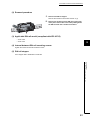
1
SAFETY PRECAUTIONS
(Read these precautions before using this product.)
Before using this product, please read this manual and the relevant manuals carefully and pay full attention
to safety to handle the product correctly.
The precautions given in this manual are concerned with this product only. For the safety precautions of the
programmable controller system, refer to the user's manual for the CPU module used.
In this manual, the safety precautions are classified into two levels: "
WARNING" and "
CAUTION".
WARNING
Indicates that incorrect handling may cause hazardous conditions,
resulting in death or severe injury.
CAUTION
Indicates that incorrect handling may cause hazardous conditions,
resulting in minor or moderate injury or property damage.
Under some circumstances, failure to observe the precautions given under "
CAUTION" may lead to
serious consequences.
Observe the precautions of both levels because they are important for personal and system safety.
Make sure that the end users read this manual and then keep the manual in a safe place for future
reference.
[Design Precautions]
WARNING
● In the case of a communication failure in CC-Link IE Field Network, the status of the error station will
be as follows:
(1) All inputs from remote I/O stations connected to the CC-Link network are turned off.
(2) All outputs from remote I/O stations connected to the CC-Link network are turned off.
Check Data link status (each station) (SW00B0 to SW00B7) and configure an interlock circuit in the
sequence program to ensure that the entire system will operate safely. Incorrect output or malfunction
due to a communication failure may result in an accident.
● Outputs may remain on or off due to a failure of a bridge module. Configure an external circuit for
monitoring output signals that could cause a serious accident.
● Do not use any "use prohibited" signals as remote input or output signals because the "use prohibited"
signals are used for the system. Do not write any data to the "use prohibited" area in the remote
register.
If these operations are performed, correct operation of the module cannot be guaranteed.
1
[Design Precautions]
CAUTION
● Do not install the control lines or communication cables together with the main circuit lines or power
cables. Keep a distance of 100mm or more between them. Failure to do so may result in malfunction
due to noise.
[Installation Precautions]
WARNING
● Shut off the external power supply (all phases) used in the system before mounting or removing a
module. Failure to do so may result in electric shock or cause the module to fail or malfunction.
[Installation Precautions]
CAUTION
● Use the module in an environment that meets the general specifications in this manual. Failure to do
so may result in electric shock, fire, malfunction, or damage to or deterioration of the product.
● Do not directly touch any conductive parts and electronic components of the module. Doing so can
cause malfunction or failure of the module.
● Securely fix the module with a DIN rail.
● Securely connect the cable connectors. Poor contact may cause malfunction.
[Wiring Precautions]
WARNING
● Shut off the external power supply (all phases) used in the system before wiring. Failure to do so may
result in electric shock or cause the module to fail or malfunction.
[Wiring Precautions]
CAUTION
● Tighten any unused terminal screws within the specified torque range. Undertightening can cause
short circuit due to contact with a solderless terminal.
● Use applicable solderless terminals and tighten them within the specified torque range. If any spade
solderless terminal is used, it may be disconnected when a terminal block screw comes loose,
resulting in failure.
● Check the rated voltage and terminal layout before wiring to the module, and connect the cables
correctly. Connecting a power supply with a different voltage rating or incorrect wiring may cause a fire
or failure.
● Tighten the terminal block screws within the specified torque range. Undertightening can cause short
circuit, fire, or malfunction. Overtightening can damage the screw and/or module, resulting in drop,
short circuit, fire, or malfunction.
2
[Wiring Precautions]
CAUTION
● Prevent foreign matter such as dust or wire chips from entering the module. Such foreign matter can
cause a fire, failure, or malfunction.
● Place the cables in a duct or clamp them. If not, dangling cable may swing or inadvertently be pulled,
resulting in damage to the module or cables or malfunction due to poor contact.
● Do not install the control lines or communication cables together with the main circuit lines or power
cables. Keep a distance of 100mm or more between them. Failure to do so may result in malfunction
due to noise.
● When disconnecting the cable from the module, do not pull the cable by the cable part. For the cable
with connector, hold the connector part of the cable. For the cable connected to the terminal block,
loosen the terminal screw. Pulling the cable connected to the module may result in malfunction or
damage to the module or cable.
● When an overcurrent caused by an error of an external device or a failure of the programmable
controller flows for a long time, it may cause smoke and fire. To prevent this, configure an external
safety circuit, such as a fuse.
[Startup and Maintenance Precautions]
WARNING
● Do not touch any terminal while power is on. Doing so will cause electric shock or malfunction.
● Shut off the external power supply (all phases) used in the system before cleaning the module or
retightening the terminal block screws. Failure to do so may result in electric shock.
[Startup and Maintenance Precautions]
CAUTION
● Do not disassemble or modify the module. Doing so may cause failure, malfunction, injury, or a fire.
● Do not drop or apply strong shock to the module. Doing so may damage the module.
● Shut off the external power supply (all phases) used in the system before mounting or removing a
module. Failure to do so may cause the module to fail or malfunction.
● After the first use of the terminal block, the number of connections/disconnections is limited to 50
times (in accordance with IEC 61131-2). Exceeding the limit may cause malfunction.
● Before handling the module, touch a conducting object such as a grounded metal to discharge the
static electricity from the human body. Failure to do so may cause the module to fail or malfunction.
[Disposal Precautions]
CAUTION
● When disposing of this product, treat it as industrial waste.
3
CONDITIONS OF USE FOR THE PRODUCT
(1) Mitsubishi programmable controller ("the PRODUCT") shall be used in conditions;
i) where any problem, fault or failure occurring in the PRODUCT, if any, shall not lead to any major
or serious accident; and
ii) where the backup and fail-safe function are systematically or automatically provided outside of
the PRODUCT for the case of any problem, fault or failure occurring in the PRODUCT.
(2) The PRODUCT has been designed and manufactured for the purpose of being used in general
industries.
MITSUBISHI SHALL HAVE NO RESPONSIBILITY OR LIABILITY (INCLUDING, BUT NOT
LIMITED TO ANY AND ALL RESPONSIBILITY OR LIABILITY BASED ON CONTRACT,
WARRANTY, TORT, PRODUCT LIABILITY) FOR ANY INJURY OR DEATH TO PERSONS OR
LOSS OR DAMAGE TO PROPERTY CAUSED BY the PRODUCT THAT ARE OPERATED OR
USED IN APPLICATION NOT INTENDED OR EXCLUDED BY INSTRUCTIONS, PRECAUTIONS,
OR WARNING CONTAINED IN MITSUBISHI'S USER, INSTRUCTION AND/OR SAFETY
MANUALS, TECHNICAL BULLETINS AND GUIDELINES FOR the PRODUCT.
("Prohibited Application")
Prohibited Applications include, but not limited to, the use of the PRODUCT in;
• Nuclear Power Plants and any other power plants operated by Power companies, and/or any
other cases in which the public could be affected if any problem or fault occurs in the PRODUCT.
• Railway companies or Public service purposes, and/or any other cases in which establishment of
a special quality assurance system is required by the Purchaser or End User.
• Aircraft or Aerospace, Medical applications, Train equipment, transport equipment such as
Elevator and Escalator, Incineration and Fuel devices, Vehicles, Manned transportation,
Equipment for Recreation and Amusement, and Safety devices, handling of Nuclear or
Hazardous Materials or Chemicals, Mining and Drilling, and/or other applications where there is a
significant risk of injury to the public or property.
Notwithstanding the above, restrictions Mitsubishi may in its sole discretion, authorize use of the
PRODUCT in one or more of the Prohibited Applications, provided that the usage of the PRODUCT
is limited only for the specific applications agreed to by Mitsubishi and provided further that no
special quality assurance or fail-safe, redundant or other safety features which exceed the general
specifications of the PRODUCTs are required. For details, please contact the Mitsubishi
representative in your region.
4
INTRODUCTION
Thank you for purchasing the CC-Link IE Field Network – CC-Link bridge module (hereafter abbreviated as bridge
module).
This manual describes the procedures, system configuration, parameter settings, functions, and troubleshooting of the
bridge module.
Before using this product, please read this manual and the relevant manuals carefully and develop familiarity with the
functions and performance of the bridge module to handle the product correctly.
When applying the program examples introduced in this manual to an actual system, ensure the applicability and
confirm that it will not cause system control problems.
Remark
Unless otherwise specified, this manual describes the program examples in which the bridge module has been set to the
station number 1.
For details on station numbers, refer to the following.
User's manual for the master/local module used
5
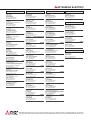
RELEVANT MANUALS
(1) CC-Link IE Field Network (relevant) manuals
When using CC-Link IE Field Network for the first time, refer to CC-Link IE Field Network Master/Local Module
User's Manual first. The following shows the structure of the CC-Link IE Field Network manuals.
Manual name
Description
<Manual number, model code>
MELSEC-Q CC-Link IE Field Network Master/Local Module User's
Overview of CC-Link IE Field Network, and specifications,
Manual
procedures before operation, system configuration, installation,
wiring, settings, functions, programming, and troubleshooting of
<SH-080917ENG, 13JZ47>
the QJ71GF11-T2
MELSEC-L CC-Link IE Field Network Master/Local Module User's
Overview of CC-Link IE Field Network, and specifications,
Manual
procedures before operation, system configuration, installation,
wiring, settings, functions, programming, and troubleshooting of
<SH-080972ENG, 13JZ54>
the LJ71GF11-T2
(2) Operating manual
Manual name
Description
<Manual number, model code>
GX Works2 Version 1 Operating Manual (Common)
System configuration, parameter settings, and online
operations of GX Works2, which are common to Simple projects
<SH-080779ENG, 13JU63>
6
and Structured projects
Memo
7
CONTENTS
CONTENTS
SAFETY PRECAUTIONS . . . . . . . . . . . . . . . . . . . . . . . . . . . . . . . . . . . . . . . . . . . . . . . . . . . . . . . . . . . . . 1
CONDITIONS OF USE FOR THE PRODUCT . . . . . . . . . . . . . . . . . . . . . . . . . . . . . . . . . . . . . . . . . . . . . 4
INTRODUCTION . . . . . . . . . . . . . . . . . . . . . . . . . . . . . . . . . . . . . . . . . . . . . . . . . . . . . . . . . . . . . . . . . . . . 5
RELEVANT MANUALS . . . . . . . . . . . . . . . . . . . . . . . . . . . . . . . . . . . . . . . . . . . . . . . . . . . . . . . . . . . . . . . 6
MANUAL PAGE ORGANIZATION . . . . . . . . . . . . . . . . . . . . . . . . . . . . . . . . . . . . . . . . . . . . . . . . . . . . . . 11
TERMS . . . . . . . . . . . . . . . . . . . . . . . . . . . . . . . . . . . . . . . . . . . . . . . . . . . . . . . . . . . . . . . . . . . . . . . . . . 12
PACKING LIST. . . . . . . . . . . . . . . . . . . . . . . . . . . . . . . . . . . . . . . . . . . . . . . . . . . . . . . . . . . . . . . . . . . . . 14
CHAPTER 1 BRIDGE MODULE
1.1
Application . . . . . . . . . . . . . . . . . . . . . . . . . . . . . . . . . . . . . . . . . . . . . . . . . . . . . . . . . . . . . . . . 15
1.2
Features . . . . . . . . . . . . . . . . . . . . . . . . . . . . . . . . . . . . . . . . . . . . . . . . . . . . . . . . . . . . . . . . . . 15
CHAPTER 2 PART NAMES
17
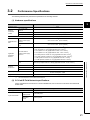
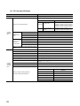
CHAPTER 3 SPECIFICATIONS
20
3.1
General Specifications . . . . . . . . . . . . . . . . . . . . . . . . . . . . . . . . . . . . . . . . . . . . . . . . . . . . . . . 20
3.2
Performance Specifications . . . . . . . . . . . . . . . . . . . . . . . . . . . . . . . . . . . . . . . . . . . . . . . . . . . 21
3.3
Function List . . . . . . . . . . . . . . . . . . . . . . . . . . . . . . . . . . . . . . . . . . . . . . . . . . . . . . . . . . . . . . . 23
3.4
Flow of Data during Communications . . . . . . . . . . . . . . . . . . . . . . . . . . . . . . . . . . . . . . . . . . . . 24
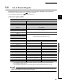
3.5
List of Remote I/O Signals . . . . . . . . . . . . . . . . . . . . . . . . . . . . . . . . . . . . . . . . . . . . . . . . . . . . 26
3.6
List of Remote Register . . . . . . . . . . . . . . . . . . . . . . . . . . . . . . . . . . . . . . . . . . . . . . . . . . . . . . 27
3.7
Example of Link Device Assignment. . . . . . . . . . . . . . . . . . . . . . . . . . . . . . . . . . . . . . . . . . . . . 29
3.8
List of Remote Buffer Memory Areas . . . . . . . . . . . . . . . . . . . . . . . . . . . . . . . . . . . . . . . . . . . . 31
CHAPTER 4 THE PROCEDURE BEFORE OPERATION
32
CHAPTER 5 SYSTEM CONFIGURATON
34
5.1
Network Configuration . . . . . . . . . . . . . . . . . . . . . . . . . . . . . . . . . . . . . . . . . . . . . . . . . . . . . . . 34
5.2
Applicable Systems. . . . . . . . . . . . . . . . . . . . . . . . . . . . . . . . . . . . . . . . . . . . . . . . . . . . . . . . . . 35
5.3
Precautions . . . . . . . . . . . . . . . . . . . . . . . . . . . . . . . . . . . . . . . . . . . . . . . . . . . . . . . . . . . . . . . . 36
CHAPTER 6 INSTALLATION AND WIRING
6.1
6.2
6.3
6.4
37
Station Number Setting . . . . . . . . . . . . . . . . . . . . . . . . . . . . . . . . . . . . . . . . . . . . . . . . . . . . . . . 37
6.1.1
Station number setting of the bridge module . . . . . . . . . . . . . . . . . . . . . . . . . . . . . . . . . . . . . 37
6.1.2
Station number setting of a CC-Link remote station . . . . . . . . . . . . . . . . . . . . . . . . . . . . . . . . 38
Installation Environment and Installation Position. . . . . . . . . . . . . . . . . . . . . . . . . . . . . . . . . . . 39
6.2.1
Installation environment . . . . . . . . . . . . . . . . . . . . . . . . . . . . . . . . . . . . . . . . . . . . . . . . . . . . . 39
6.2.2
Installation position . . . . . . . . . . . . . . . . . . . . . . . . . . . . . . . . . . . . . . . . . . . . . . . . . . . . . . . . . 39
6.2.3
Installation direction . . . . . . . . . . . . . . . . . . . . . . . . . . . . . . . . . . . . . . . . . . . . . . . . . . . . . . . . 40
Installation . . . . . . . . . . . . . . . . . . . . . . . . . . . . . . . . . . . . . . . . . . . . . . . . . . . . . . . . . . . . . . . . . 41
6.3.1
8
15
Mounting a module on a DIN rail . . . . . . . . . . . . . . . . . . . . . . . . . . . . . . . . . . . . . . . . . . . . . . 41
Wiring . . . . . . . . . . . . . . . . . . . . . . . . . . . . . . . . . . . . . . . . . . . . . . . . . . . . . . . . . . . . . . . . . . . . 44
6.4.1
Wiring with a terminal block for module power supply and FG. . . . . . . . . . . . . . . . . . . . . . . . 44
6.4.2
Wiring of an Ethernet cable . . . . . . . . . . . . . . . . . . . . . . . . . . . . . . . . . . . . . . . . . . . . . . . . . . 46
6.4.3
Wiring of a CC-Link dedicated cable . . . . . . . . . . . . . . . . . . . . . . . . . . . . . . . . . . . . . . . . . . . 49
CHAPTER 7 VARIOUS SETTINGS
53
7.1
Parameter Settings for CC-Link IE Field Network . . . . . . . . . . . . . . . . . . . . . . . . . . . . . . . . . . 53
7.2
Parameter Settings for CC-Link . . . . . . . . . . . . . . . . . . . . . . . . . . . . . . . . . . . . . . . . . . . . . . . . 54
CHAPTER 8 PROGRAMMING
59
8.1
Precautions for Programming . . . . . . . . . . . . . . . . . . . . . . . . . . . . . . . . . . . . . . . . . . . . . . . . . . 59
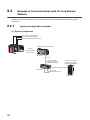
8.2
Example of Communications with CC-Link Remote Stations . . . . . . . . . . . . . . . . . . . . . . . . . . 62
8.2.1
System configuration example . . . . . . . . . . . . . . . . . . . . . . . . . . . . . . . . . . . . . . . . . . . . . . . . 62
8.2.2
Setting of CC-Link IE Field Network. . . . . . . . . . . . . . . . . . . . . . . . . . . . . . . . . . . . . . . . . . . . 64
8.2.3
Setting of CC-Link . . . . . . . . . . . . . . . . . . . . . . . . . . . . . . . . . . . . . . . . . . . . . . . . . . . . . . . . . 66
8.2.4
Program example. . . . . . . . . . . . . . . . . . . . . . . . . . . . . . . . . . . . . . . . . . . . . . . . . . . . . . . . . . 67
CHAPTER 9 TROUBLESHOOTING
69
9.1
Operation Upon Error . . . . . . . . . . . . . . . . . . . . . . . . . . . . . . . . . . . . . . . . . . . . . . . . . . . . . . . . 69
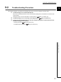
9.2
Troubleshooting Procedure . . . . . . . . . . . . . . . . . . . . . . . . . . . . . . . . . . . . . . . . . . . . . . . . . . . 71
9.3
CC-Link IE Field Network Diagnostics . . . . . . . . . . . . . . . . . . . . . . . . . . . . . . . . . . . . . . . . . . . 72
9.4
How to Check Error Codes and Warning Codes . . . . . . . . . . . . . . . . . . . . . . . . . . . . . . . . . . . 74
9.5
9.6
9.7
9.8
List of Error Codes and Warning Codes . . . . . . . . . . . . . . . . . . . . . . . . . . . . . . . . . . . . . . . . . . 76
9.5.1
Errors that occur in the bridge module . . . . . . . . . . . . . . . . . . . . . . . . . . . . . . . . . . . . . . . . . . 76
9.5.2
Errors that occur in CC-Link IE Field Network . . . . . . . . . . . . . . . . . . . . . . . . . . . . . . . . . . . . 78
9.5.3
Errors that occur in CC-Link. . . . . . . . . . . . . . . . . . . . . . . . . . . . . . . . . . . . . . . . . . . . . . . . . . 79
9.5.4
Other errors . . . . . . . . . . . . . . . . . . . . . . . . . . . . . . . . . . . . . . . . . . . . . . . . . . . . . . . . . . . . . . 81
Checking the LEDs . . . . . . . . . . . . . . . . . . . . . . . . . . . . . . . . . . . . . . . . . . . . . . . . . . . . . . . . . . 82
9.6.1
POWER LED . . . . . . . . . . . . . . . . . . . . . . . . . . . . . . . . . . . . . . . . . . . . . . . . . . . . . . . . . . . . . 82
9.6.2
LEDs of CC-Link IE Field Network . . . . . . . . . . . . . . . . . . . . . . . . . . . . . . . . . . . . . . . . . . . . . 82
9.6.3
CC-Link LEDs . . . . . . . . . . . . . . . . . . . . . . . . . . . . . . . . . . . . . . . . . . . . . . . . . . . . . . . . . . . . 85
Troubleshooting by Symptom . . . . . . . . . . . . . . . . . . . . . . . . . . . . . . . . . . . . . . . . . . . . . . . . . . 87
9.7.1
CC-Link IE Field Network. . . . . . . . . . . . . . . . . . . . . . . . . . . . . . . . . . . . . . . . . . . . . . . . . . . . 87
9.7.2
CC-Link . . . . . . . . . . . . . . . . . . . . . . . . . . . . . . . . . . . . . . . . . . . . . . . . . . . . . . . . . . . . . . . . . 87
9.7.3
Bridge module . . . . . . . . . . . . . . . . . . . . . . . . . . . . . . . . . . . . . . . . . . . . . . . . . . . . . . . . . . . . 91
Unit Test . . . . . . . . . . . . . . . . . . . . . . . . . . . . . . . . . . . . . . . . . . . . . . . . . . . . . . . . . . . . . . . . . . 92
APPENDICES
94
Appendix 1 Details of Remote Registers . . . . . . . . . . . . . . . . . . . . . . . . . . . . . . . . . . . . . . . . . . . . . . 94
Appendix 2 Details of Remote Buffer Memory . . . . . . . . . . . . . . . . . . . . . . . . . . . . . . . . . . . . . . . . . . 98
Appendix 3 Data Link Processing Time . . . . . . . . . . . . . . . . . . . . . . . . . . . . . . . . . . . . . . . . . . . . . . 116
Appendix 3.1
Device transfer time . . . . . . . . . . . . . . . . . . . . . . . . . . . . . . . . . . . . . . . . . 117
Appendix 3.2
Processing time of CC-Link . . . . . . . . . . . . . . . . . . . . . . . . . . . . . . . . . . . . 118
Appendix 3.3
Transmission delay time . . . . . . . . . . . . . . . . . . . . . . . . . . . . . . . . . . . . . . 119
Appendix 4 EMC and Low Voltage Directives . . . . . . . . . . . . . . . . . . . . . . . . . . . . . . . . . . . . . . . . . 123
Appendix 4.1
Measures to comply with the EMC Directive . . . . . . . . . . . . . . . . . . . . . . . . . 123
Appendix 4.2
Requirements to compliance with the Low Voltage Directive . . . . . . . . . . . . . . . 128
9
Appendix 5 Checking the Serial Number and Function Version . . . . . . . . . . . . . . . . . . . . . . . . . . . 129
Appendix 6 External Dimensions . . . . . . . . . . . . . . . . . . . . . . . . . . . . . . . . . . . . . . . . . . . . . . . . . . . 130
INDEX
131
REVISIONS . . . . . . . . . . . . . . . . . . . . . . . . . . . . . . . . . . . . . . . . . . . . . . . . . . . . . . . . . . . . . . . . . . . . . . 132
WARRANTY . . . . . . . . . . . . . . . . . . . . . . . . . . . . . . . . . . . . . . . . . . . . . . . . . . . . . . . . . . . . . . . . . . . . . 133
10
MANUAL PAGE ORGANIZATION
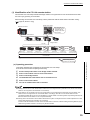
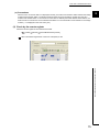
In this manual, pages are organized and the symbols are used as shown below.
The following illustration is for explanation purpose only, and should not be referred to as an actual documentation.
"" is used for window
names and items.
shows operating
procedures.
shows mouse
operations.*1
The chapter of
the current page is shown.
[ ] is used for items in
the menu bar and the
project window.
The section of
the current page is shown.
Ex. shows setting or
operating examples.
shows reference
manuals.
shows notes that
require attention.
shows reference
pages.
shows useful
information.
*1
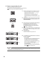
The mouse operation example is provided below.
Menu bar
Ex.
[Online]
[Write to PLC...]
Select [Online] on the menu bar,
and then select [Write to PLC...].
A window selected in the view selection area is displayed.
Ex.
[Parameter]
Project window
[PLC Parameter]
Select [Project] from the view selection
area to open the Project window.
In the Project window, expand [Parameter] and
select [PLC Parameter].
View selection area
11
TERMS
Unless otherwise specified, this manual uses the following terms.
Term
CC-Link
Description
A field network system where data processing for control and information can be simultaneously performed
at high speed
CC-Link IE Field Network
A high-speed and large-capacity open field network that is based on Ethernet (1000BASE-T)
CC-Link dedicated cable
The abbreviation for the Ver.1.10-compatible CC-Link dedicated cable
CC-Link remote station
A generic term for CC-Link remote I/O stations and remote device stations
GX Works2
The product name of the software package for the MELSEC programmable controllers
Intelligent device station
A station that exchanges I/O signals (bit data) and I/O data (word data) with the master station by cyclic
transmission. This station responds to a transient transmission request from another station and also issues
a transient transmission request to another station.
Disconnection
A process of stopping data link if a data link error occurs
Cyclic transmission
A function by which data are periodically exchanged among stations on the same network using link devices
(RX, RY, RWw, and RWr)
Slave station
A generic term for stations other than a master station: local station, remote I/O station, remote device
station, and intelligent device station
Dedicated instruction
An instruction that simplifies programming for using functions of intelligent function modules
Relay station
A station that includes two or more network modules. Data are passed through this station to stations on
other networks.
Data link
A generic term for cyclic transmission and transient transmission
Device
A device (X, Y, M, D, or others) in a CPU module
Transient transmission
A function of communication with another station, which is used when requested by a dedicated instruction
or GX Works2
Buffer memory
A memory in a bridge module, where data (such as setting values and monitoring values) are stored
Return
A process of restarting data link when a station recovers from an error
Bridge module
The abbreviation for the NZ2GF-CCB CC-Link IE Field Network – CC-Link bridge module
Master/local module
A generic term for CC-Link IE Field Network master/local modules
Master station
A station that controls the entire network.
This station can perform cyclic transmission and transient transmission with all stations.
Only one master station can be used in a network.
("Master station" after Chapter 1 in this manual is a CC-Link IE Field Network master station. A master
station on CC-Link is described as "CC-Link master station".)
Reserved station
A station reserved for future use. This station is not actually connected, but counted as a connected station.
Remote I/O station
A station that exchanges I/O signals (bit data) with the master station by cyclic transmission
Remote output (RY)
Bit data output from the master station to a slave station (For some areas in a local station, data are output
in the opposite direction.)
User's manual for the master/local module used
Remote device station
A station that exchanges I/O signals (bit data) and I/O data (word data) with the master station by cyclic
transmission. This station responds to a transient transmission request from another station.
Link device
A device (RX, RY, RWr, or RWw) in a module on CC-Link IE Field Network and CC-Link
Remote input (RX)
Bit data input from a slave station to the master station (For some areas in a local station, data are output in
the opposite direction.)
User's manual for the master/local module used
Remote buffer memory
Buffer memory in a remote device station
Remote register (RWr)
Word data input from a slave station to the master station (For some areas in a local station, data are output
in the opposite direction.)
Remote register (RWw)
Word data output from the master station to a slave station (For some areas in a local station, data are
output in the opposite direction.)
User's manual for the master/local module used
User's manual for the master/local module used
Link scan (link scan time)
12
Time required for all stations in a system to transmit data. The link scan time depends on data volume and
the number of transient transmission requests.
Term
Description
Link special relay (SB)
Bit data that indicates the module operating status and data link status of CC-Link IE Field Network and CCLink
Link special register (SW)
Word data that indicates the module operating status and data link status of CC-Link IE Field Network and
CC-Link
Local station
A station that performs cyclic transmission and transient transmission with the master station and other local
stations.
The station is controlled by programs in the CPU module or other equivalent modules on the station.
13
PACKING LIST
The following items are included in the package of this product. Before use, check that all the items are included.
NZ2GF-CCB
Bridge module
Safety Guidelines
A set of terminating resistors for CC-Link
Terminating resistor 110 1/2W
(brown-brown-brown, gold)
14
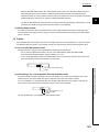
2
Notes about
the terminating resistors
CHAPTER 1 BRIDGE MODULE
CHAPTER 1
BRIDGE MODULE
1
This chapter describes the application and features of the bridge module.
1.1
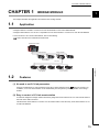
Application
A bridge module is a module to connect a CC-Link remote station to CC-Link IE Field Network.
A bridge module allows a CC-Link Ver.1-compatible CC-Link remote station to connect to CC-Link IE Field Network.
For the functions of CC-Link IE Field Network, refer to the following.
User's manual for the master/local module used
Master/local module
CC-Link IE Field Network
Bridge module
CC-Link IE Field Network
slave stations
CC-Link
1.2
1.1 Application
CC-Link remote
I/O stations
CC-Link remote
device stations
Features
(1) No need to set CC-Link parameters
A bridge module allows CC-Link parameters to be set by switch operation alone. (
Page 54, Section 7.2)
In addition, a CC-Link remote station can be added easily into the system by switch operation on the bridge
module.
(2) Easy to control a CC-Link remote station
Link devices assigned to bridge modules are directly assigned to the link devices of a CC-Link remote station in
the order of the station numbers.
This allows the master station to control a CC-Link remote station in the same way as the slave stations on CCLink IE Field Network.
15
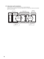
(3) Independent cyclic transmission
Cyclic transmission of CC-Link is independent from CC-Link IE Field Network.
In addition, the cyclic transmission of CC-Link IE Field Network is not affected even when the communication
status of CC-Link changes.
Master station
CPU module
Data
in CPU
Bridge module
Master/local module
Cyclic
transmission
data in RX/RY and
RWr/RWw on
the CC-Link IE Field
Network side
Link scan time of
CC-Link IE Field
Network
16
CC-Link
remote station
Cyclic
transmission
data in RX/RY and
RWr/RWw on the
CC-Link side
Link scan time of
CC-Link
CHAPTER 2 PART NAMES
CHAPTER 2
PART NAMES
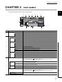
2
This chapter describes the part names of a bridge module.
11)
1)
5)
2)
6)
7)
4)
3)
8)
No.
10)
Name
POWER LED (green)
1)
Indicates the power supply status of the bridge module.
Power supply on
OFF
Power supply off
RUN LED (green)
Indicates the status of CC-Link IE Field Network.
Indicates the operating status of the bridge module.
ON
Operating normally
OFF
A serious error has occurred.
MODE LED (green)
2)
Description
ON
CC-Link IE Field Network LED
Indicates the mode of the bridge module.
ON
In the online mode
Flashing
In the unit test mode
OFF
Unit test completed
D LINK LED (green)
ON
9)
Indicates the data link status.
Performing data link (cyclic transmission in progress)
Flashing
Performing data link (cyclic transmission stopped)
OFF
Not performing data link (disconnected)
ERR. LED (red)
Indicates the error status of CC-Link IE Field Network of the bridge module.
ON
A moderate error or serious error has occurred.
Flashing
A warning has occurred.
OFF
Operating normally
PORT1 connector for connecting CC-Link IE Field Network. (RJ45 connector)
P1
Connect an Ethernet cable. (
Page 46, Section 6.4.2)
There are no restrictions on the connecting order of the "P1" connector and "P2" connector.
L ER LED
(red)
3)
LINK LED
(green)
ON
• The module has received abnormal data.
• The module is performing loopback.
OFF
• The module has received normal data.
• The module has not performed loopback.
ON
Linkup in progress.
OFF
Linkdown in progress.
PORT2 connector for connecting CC-Link IE Field Network. (RJ45 connector)
P2
Connect an Ethernet cable. (
Page 46, Section 6.4.2)
There are no restrictions on the connecting order of the "P1" connector and "P2" connector.
L ER LED (red)
LINK LED (green)
(Same as the LEDs of the "P1" connector)
17
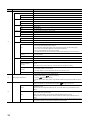
No.
Name
CC-Link LED
Indicates the status of CC-Link.
RUN LED (green)
Indicates the operating status of the bridge module.
ON
Operating normally
OFF
A hardware failure or watchdog timer error has occurred.
L RUN LED (green)
ON
OFF
SD LED (green)
Indicates the data link status.
Performing data link
Not performing data link
Indicates whether the module is sending data.
ON
Sending data
OFF
Not sending data
RD LED (green)
ON
OFF
MST LED (green)
4)
Description
Indicates whether the module is receiving data.
Receiving data
Not receiving data
Indicates whether the bridge module is operating as a CC-Link master station.
ON
Operating as a CC-Link master station.
Flashing
Line test or unit test is being executed.
ERR. LED (red)
Indicates the error status of CC-Link of the bridge module.
ON
Any of the following errors has occurred.
• An error has been detected in all the stations.
• The transmission speed/mode setting switch of the bridge module is out of the setting range.
• Two or more CC-Link master stations are connected on the same line.
• The CC-Link parameters have not been set correctly.
• The cable is disconnected. Or the transmission path has been affected by noise or other factors.
Flashing
A faulty station has been detected in the data link. Or the same station number is used for multiple CCLink remote stations.
OFF
Operating normally
L ERR LED (red)
Indicates the data link error of CC-Link of the bridge module.
ON
A data link error has occurred at the own station.
Flashing at regular
intervals
The setting of the transmission speed/mode setting switch was changed when the power of the module
was on.
(Note that the change of the switch may not be detected when all stations are faulty.)
Flashing at irregular
intervals
The communications are unstable due to the following reasons.
• A terminating resistor is not connected.
• The bridge module or CC-Link dedicated cable has been affected by noise.
OFF
Operating normally
A rotary switch used for the following setting and test.
• Station number setting (
5)
• Unit test (
Page 92, Section 9.8)
To set the station number setting switch, use a flathead screwdriver having a tipped width of 3.5mm or
less.
Startup mode switch
Sets how to read the CC-Link parameters at the startup. (
Page 54, Section 7.2)
AUTO
Starts up CC-Link by the automatic CC-Link startup, and starts the data refresh after the module is
powered on or reset.
When the switch is changed from PRM to AUTO, CC-Link also starts up by the automatic CC-Link
startup.
SET
Generates CC-Link parameters from the station information of the connected CC-Link remote station
and stores the data in the flash ROM.
Writing to the flash ROM is not executed if a parameter-related error has occurred.
When the switch is changed from SET to AUTO, the data refresh starts by the automatic CC-Link
startup.
PRM
Reads the CC-Link parameters from the flash ROM to start up CC-Link and starts the data refresh when
the module is powered on or the switch is changed from AUTO to PRM.
6)
18
Page 37, Section 6.1)
Station number setting switch
CHAPTER 2 PART NAMES
No.
Name
Description
Sets the transmission speed and mode of CC-Link. (Default: 0)
Set the same value of the transmission speed for all stations.
Mode
Online
7)
Transmission speed/mode setting switch
Line test (
Page 58, Section 7.2 (3))
Setting not allowed
Transmission speed
setting
Switch number
Transmission speed
156kbps
0
Transmission speed
625kbps
1
Transmission speed
2.5Mbps
2
Transmission speed
5Mbps
3
Transmission speed
10Mbps
4
Transmission speed
156kbps
5
Transmission speed
625kbps
6
Transmission speed
2.5Mbps
7
Transmission speed
5Mbps
8
Transmission speed
10Mbps
9
-
A to F
Terminal block for module power supply
and FG
A terminal block to connect the module power supply (24VDC) and FG.
9)
Terminal block for CC-Link
For connecting the Ver.1.10-compatible CC-Link dedicated cable. (
Page 49, Section 6.4.3)
The SLD terminal and FG terminal are connected inside the module.
The module can be replaced without disconnecting the signal line connected to the terminal block
because the terminal block has the two-piece structure.
Before connecting or removing the terminal block, power off the module.
10)
DIN rail hook
A hook for mounting a module on a DIN rail.
11)
RESET switch
Resets the hardware and initializes the module when the station number setting of CC-Link IE Field
Network or the transmission speed or mode setting of CC-Link is changed.
8)
19
2
CHAPTER 3
SPECIFICATIONS
This chapter describes the specifications of the bridge module.
3.1
General Specifications
The following table lists the general specifications of the bridge module.
Item
Specifications
Operating
ambient
temperature
0 to 55°C
Storage ambient
temperature
-25 to 75°C
Operating
ambient humidity
5 to 95%RH, non-condensing
Storage ambient
humidity
Compliant with
JIS B 3502 and
IEC 61131-2
Vibration
resistance
Under
intermittent
vibration
Under continuous
vibration
Shock resistance
Frequency
Constant
acceleration
Half amplitude
5 to 8.4Hz
-
3.5mm
8.4 to 150Hz
9.8m/s2
-
5 to 8.4Hz
-
1.75mm
8.4 to 150Hz
4.9m/s2
-
Number of
sweeps
10 times each in
X, Y, and Z
directions
-
Compliant with JIS B 3502 and IEC 61131-2 (147m/s2, three times each in X, Y, and Z directions)
Operating
atmosphere
No corrosive gases
Operating
0 to 2000m
altitude*1
Installation
location
Inside a control panel
Overvoltage
II or less
category*2
Pollution
2 or less
degree*3
Equipment class
*1
Class I
Do not use or store the bridge module under pressure higher than the atmospheric pressure of altitude 0m. Doing so may
cause malfunction. When using the bridge module under pressure, please consult your local Mitsubishi representative.
This indicates the section of the power supply to which the equipment is assumed to be connected between the public
electrical power distribution network and the machinery within premises.
Category II applies to equipment for which electrical power is supplied from fixed facilities. The surge voltage withstand
level for the equipment with the rated voltage of 300V or less is 2500V.
This index indicates the degree to which conductive material is generated in terms of the environment in which the
equipment is used.
Pollution degree 2 is when only non-conductive pollution occurs. A temporary conductivity caused by condensing must
be expected occasionally.
*2
*3
To make the bridge module comply with the EMC Directive, refer to "EMC and Low Voltage Directives" in this manual.
(
20
Page 123, Appendix 4)
CHAPTER 3 SPECIFICATIONS
3.2
Performance Specifications
The following table lists the performance specifications of the bridge module.
(1) Hardware specifications
Item
Protection code
IP2X
CC-Link IE Field
Network
External
connection
system
RJ45 connector
Module power supply
Terminal block for module power supply and FG
CC-Link
Terminal block for CC-Link (two-piece, M3 screw)
Applicable DIN rail
Applicable wire
size
3
Specifications
TH35-7.5Fe, TH35-7.5Al (compliant with IEC 60715)
Terminal block for
module power supply
and FG
Core: 0.5 to 1.5mm2 (20 to 16 AWG)
Terminal block for CCLink
Core: 0.3 to 1.5mm2 (22 to 16 AWG)
TE 0.5-10 (Nichifu Co. Ltd.) [Applicable wire size: 0.5mm2]
TE 0.75-10 (Nichifu Co. Ltd.) [Applicable wire size: 0.75mm2]
Terminal block for
module power supply
Applicable
solderless
terminal
and FG*1
TE 1.0-10 (Nichifu Co. Ltd.) [Applicable wire size: 0.9 to 1.0mm2]
TE 1.5-10 (Nichifu Co. Ltd.) [Applicable wire size: 1.25 to 1.5mm2]
AI 0.5-10WH (Phoenix Contact Co. Ltd.) [Applicable wire size: 0.5mm2]
AI 0.75-10GY (Phoenix Contact Co. Ltd.) [Applicable wire size: 0.75mm2]
AI 1-10RD (Phoenix Contact Co. Ltd.) [Applicable wire size: 1.0mm2]
AI 1.5-10BK (Phoenix Contact Co. Ltd.) [Applicable wire size: 1.5mm2]
External
dimensions
3.2 Performance Specifications
Terminal block for CCLink
RAV1.25-3 (compliant with JIS C 2805) [Applicable wire size: 0.3 to 1.25mm2]
H
69.5mm
W
160mm
D
68mm
24VDC (20.4 to 28.8VDC)
Current consumption: 0.29A
External power supply
Weight
0.38kg
*1
Do not connect two or more wires to the terminal.
(2) CC-Link IE Field Network specifications
For the specifications of the entire CC-Link IE Field Network, refer to the user's manual for the master/local
module used.
Item
Specifications
Station type
Cyclic transmission
Intelligent device station
Number of
RX/RY points
Up to 2048 points
Number of
RWr/RWw
points
Up to 272 points
21
(3) CC-Link specifications
Item
Compatible CC-Link version
Specifications
Ver.1.10
Up to 64 modules (However, the following conditions must be satisfied.)
Item
Number of connected modules
Condition 2
Control
specifications
Maximum
number of link
points
Number of link
points per
remote station
Communication
specifications
(16 x A) + (54 x B)
2304
Remote input (RX)
2048 points
Remote output (RY)
2048 points
Remote register (RWw)
256 points (256 words)
Remote register (RWr)
256 points (256 words)
Remote input (RX)
32 points
Remote output (RY)
32 points
Remote register (RWw)
4 points (4 words)
Remote register (RWr)
4 points (4 words)
A: Number of remote I/O stations 64
B: Number of remote device stations 42
Maximum number of occupied stations per remote
station
4 stations (Ver.1.10)
Transmission speed
Selectable among 156kbps/625kbps/2.5Mbps/5Mbps/10Mbps
Communication method
Broadcast polling method
Synchronization method
Frame synchronization method
Encoding method
NRZI method
Network topology
Bus topology (RS-485)
Transmission format
HDLC compliant
Error control system
CRC (X16 + X12 + X5 + 1)
Connection cable
Ver.1.10-compatible CC-Link dedicated cable
Station-to-station distance
20cm or more
Varies according to the transmission speed
Maximum station-to-station distance
(Maximum transmission distance)
22
Number of modules
{(1 x a) + (2 x b) + (3 x c) a: Number of modules occupying 1 station
+ (4 x d)} 64
b: Number of modules occupying 2 stations
Condition 1
c: Number of modules occupying 3 stations
d: Number of modules occupying 4 stations
Transmission speed
Maximum station-to-station
distance
156kbps
1200m
625kbps
900m
2.5Mbps
400m
5Mbps
160m
10Mbps
100m
CHAPTER 3 SPECIFICATIONS
3.3
Function List
The following table lists the functions of the bridge module.
(1) Functions of CC-Link IE Field Network
Function
Description
CC-Link IE Field Network
diagnostic function
Checks for an network error from GX Works2
connected to the master station using the CC-Link IE
Field Network diagnostic function.
Page 72, Section 9.3
Module error collection function
Checks the error history of the bridge module from GX
Works2 connected to the master station using the CCLink IE Field Network diagnostic function.
Page 74, Section 9.4 (1)
Remote resetting function*1
Resets the bridge module from the master station.
Page 73, Section 9.3 (2)
*1
3
Reference
When the bridge module is reset with the remote resetting function, the CC-Link communication also stops.
(2) CC-Link functions
Function
Slave station cutoff function
Description
Reference
Disconnects the CC-Link remote station where data link
cannot be performed due to power-off or other factors,
and continues data link in normal CC-Link remote
stations.
This function prevents the entire system from going
down caused by faulty one station.
-
Automatic CC-Link startup
function
Performs CC-Link data link simply by powering on the
module.
Slave station information saving
function
Saves the slave station information performing data link
by the automatic CC-Link startup.
Temporary error invalid station
setting function
Excludes the CC-Link where an error has occurred
during data link from being detected as a faulty station.
This function is used when the CC-Link remote station
is replaced during data link for maintenance or other
purposes.
CC-Link data link stop/restart
Stops or restarts CC-Link data link using the remote
buffer memory. This function is used when data link is
Page 107, Appendix 2 (6) (b)
stopped temporarily for maintenance or other purposes.
Line test function
Checks whether a CC-Link dedicated cable is
connected correctly and the module is ready to perform
data link with the CC-Link remote station.
3.3 Function List
Automatic return function
Restarts data link when the CC-Link remote station
disconnected from data link due to power-off or other
factors returns to normal. This function shortens the
time to recover from an error.
Page 54, Section 7.2
Page 106, Appendix 2 (6) (a)
Page 54, Section 7.2
(3) Hardware functions
Function
Unit test function
Description
Checks the hardware inside the bridge module.
Reference
Page 92, Section 9.8
23
3.4
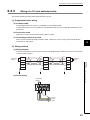
Flow of Data during Communications
The bridge module communicates with a master station and a CC-Link remote station using link devices
(RX/RY/RWr/RWw).
This section describes the flow of the link devices between the bridge module and the master station or a CC-Link
remote station.
Master/local module
CC-Link IE Field Network
Bridge module
CC-Link
remote I/O station
CC-Link
remote device station
CC-Link
remote I/O station
CC-Link
remote device station
CC-Link IE Field Network
slave station
CC-Link
CPU module
1000H
X
CC-Link
IE Field Network
slave station
Master/local module
0000H
RX
Bridge module
0000H RX
0000H
RX
0000H
RX
(1)1.
RX
(1)1.
3FFFH
1000H
Y
0000H
07FFH
07FFH
RY
0000H RY
0000H
RY
0000H
3FFFH
07FFH
RY
0000H RWr
RY
07FFH
Data such as
the operating
status of the
bridge module
0000H RWr
0000H RWr
(2)3.
(2)3.
Link
scan
W
RY
(2)2.
(2)1.
0000H
RX
(1)2.
(1)3.
Link
scan
0000H RWr
RWr
(3)3.
(3)2.
1FFFH
1000H
010FH
0000H RWw
0000H RWw
0000H RWw
(3)1.
00FFH
Data such as
the settings of
the bridge
module
0000H RWw
RWw
(4)1.
(4)2.
(4)3.
1FFFH
Master station
010FH
Station No.1
CC-Link IE Field Network
24
Station No.2
00FFH
CC-Link master station
Station No.1
CC-Link
Station No.2
CHAPTER 3 SPECIFICATIONS
(1) Remote input (RX)
1.
The data in the RX of the CC-Link remote station is stored in the RX of the bridge module by the
link scan of CC-Link.
2.
3.
The bridge module transfers the data from CC-Link to CC-Link IE Field Network.
The data in the RX of the bridge module is stored in the RX of the master station by the link scan of
3
CC-Link IE Field Network.
(2) Remote output (RY)
1.
The data in the RY of the master station is stored in the RY of the bridge module by the link scan of
CC-Link IE Field Network.
2.
3.
The bridge module transfers the data from CC-Link IE Field Network to CC-Link.
The data in the RY of the bridge module is stored in the RY of the CC-Link remote station by the
link scan of CC-Link.
(3) Remote register (RWr)
1.
Data in the RWr of the CC-Link remote device station is stored in the RWr of the bridge module by
the link scan of CC-Link.
2.
3.
The bridge module transfers the data from CC-Link to CC-Link IE Field Network.
The data in the RWr of the bridge module is stored in the RWr of the master station by the link scan
of CC-Link IE Field Network.
(4) Remote register (RWw)
The data in the RWw of the master station is stored in the RWw of the bridge module by the link
scan of CC-Link IE Field Network.
2.
3.
The bridge module transfers the data from CC-Link IE Field Network to CC-Link.
The data in the RWw of the bridge module is stored in the RWw of the CC-Link remote device
station by the link scan of CC-Link.
25
3.4 Flow of Data during Communications
1.
3.5
List of Remote I/O Signals
The following table lists the remote I/O signal (RX/RY) assignment of the bridge module.
For an assignment example, refer to
Page 29, Section 3.7.
(1) Remote input (RX)
Bridge module to master station (RX)
Address
Description
RX n+1H
RX1 of CC-Link
RX1 of the station number 1
RX1F of the station number 1
RX n+20H
RX20 of CC-Link
RX0 of the station number 2
RX1F of the station number 2
RX0 of the station number m
···
RX k+0H of CC-Link
···
RX n+k+0H
···
···
RX3F of CC-Link
···
RX n+3FH
···
···
RX1F of CC-Link
···
RX n+1FH
···
···
RX0 of the station number 1
···
RX0 of CC-Link
···
RX n+0H
RX n+k+1FH
RX k+1FH of CC-Link
RX1F of the station number m
n: The start address assigned to the bridge module by the station number setting in CC-Link IE Field Network
m: The last station number in CC-Link
k: The start address assigned to the CC-Link remote input of the last connected station number in CC-Link
(2) Remote output (RY)
Master station to bridge module (RY)
Address
Description
RY1 of CC-Link
RY1 of the station number 1
RY1F of the station number 1
RY n+20H
RY20 of CC-Link
RY0 of the station number 2
RY1F of the station number 2
RY0 of the station number m
···
RY k+0H of CC-Link
···
RY n+k+0H
···
···
RY3F of CC-Link
···
RY n+3FH
···
···
RY1F of CC-Link
···
RY n+1FH
···
···
RY0 of the station number 1
···
RY0 of CC-Link
RY n+1H
···
RY n+0H
RY n+k+1FH
RY k+1FH of CC-Link
RY1F of the station number m
n: The start address assigned to the bridge module by the station number setting in CC-Link IE Field Network
m: The last station number in CC-Link
k: The start address assigned to the CC-Link remote input of the last connected station number in CC-Link
26
CHAPTER 3 SPECIFICATIONS
3.6
List of Remote Register
The following table lists the functions and assignment of the remote register (RWr/RWw) of the bridge module.
For details on the remote register, refer to
For an assignment example, refer to
Page 94, Appendix 1 .
Page 29, Section 3.7.
3
(1) Remote register (RWr)
Bridge module to master station (RWr)
Address
Description
RWr n+0H
Bridge module operating status
RWr n+1H
Error code
RWr n+2H
Warning code
RWr n+3H
Use prohibited
RWr n+4H
CC-Link operating status
RWr n+5H
RWr n+6H to RWr n+7H
Use prohibited
RWr n+8H
RWr n+9H
RWr n+AH
Data link status of other stations on CC-Link
RWr n+BH
RWr n+CH to RWr n+FH
Use prohibited
RWr1 of CC-Link
RWr1 of the station number 1
RWr n+12H
RWr2 of CC-Link
RWr2 of the station number 1
RWr n+13H
RWr3 of CC-Link
RWr3 of the station number 1
RWr n+14H
RWr4 of CC-Link
RWr0 of the station number 2
RWr n+15H
RWr5 of CC-Link
RWr1 of the station number 2
RWr n+16H
RWr6 of CC-Link
RWr2 of the station number 2
RWr n+17H
RWr7 of CC-Link
RWr3 of the station number 2
···
RWr n+11H
···
RWr0 of the station number 1
···
RWr0 of CC-Link
RWr n+k+10H
RWr k+0H of CC-Link
RWr0 of the station number m
RWr n+k+11H
RWr k+1H of CC-Link
RWr1 of the station number m
RWr n+k+12H
RWr k+2H of CC-Link
RWr2 of the station number m
RWr n+k+13H
RWr k+3H of CC-Link
RWr3 of the station number m
3.6 List of Remote Register
RWr n+10H
n: The start address assigned to the bridge module by the station number setting in CC-Link IE Field Network
m: The last station number in CC-Link
k: The start address assigned to the CC-Link remote input of the last connected station number in CC-Link
Do not read or write the data from/to any "Use prohibited" remote registers. If the data is read or written from/to any of the
registers, correct operation of the module cannot be guaranteed.
27
(2) Remote register (RWw)
Master station to bridge module (RWw)
Address
Description
RWw n+0H
Bridge module setting
RWw n+1H to RWw n+FH
Use prohibited
RWw n+11H
RWw1 of CC-Link
RWw1 of the station number 1
RWw n+12H
RWw2 of CC-Link
RWw2 of the station number 1
RWw n+13H
RWw3 of CC-Link
RWw3 of the station number 1
RWw n+14H
RWw4 of CC-Link
RWw0 of the station number 2
RWw n+15H
RWw5 of CC-Link
RWw1 of the station number 2
RWw n+16H
RWw6 of CC-Link
RWw2 of the station number 2
RWw n+17H
RWw7 of CC-Link
RWw3 of the station number 2
···
RWw0 of the station number 1
···
RWw0 of CC-Link
···
RWw n+10H
RWw n+k+10H
RWw k+0H of CC-Link
RWw0 of the station number m
RWw n+k+11H
RWw k+1H of CC-Link
RWw1 of the station number m
RWw n+k+12H
RWw k+2H of CC-Link
RWw2 of the station number m
RWw n+k+13H
RWw k+3H of CC-Link
RWw3 of the station number m
n: The start address assigned to the bridge module by the station number setting in CC-Link IE Field Network
m: The last station number in CC-Link
k: The start address assigned to the CC-Link remote input of the last connected station number in CC-Link
Do not read or write the data from/to any "Use prohibited" remote registers. If the data is read or written from/to any of the
registers, correct operation of the module cannot be guaranteed.
28
CHAPTER 3 SPECIFICATIONS
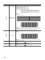
3.7
Example of Link Device Assignment
The following table lists an example of the assignment of remote I/O signals and remote registers.
Ex. Example of assignment in the following system configuration
3
Refresh parameter
Link side
Device
name
Number of
points
CPU side
Start
Device
name
Last
Number of
points
Start
Last
RX
128
0H
7FH
X
128
1000H
107FH
RY
128
0H
7FH
Y
128
1000H
107FH
RWw
32
0H
1FH
W
32
1000H
101FH
RWr
32
0H
1FH
W
32
0H
1FH
Power supply module (Q62P)
CPU module (Q10UDHCPU)
Master/local module (QJ71GF11-T2)
Bridge module (NZ2GF-CCB)
CC-Link
IE Field Network
(Network No.1)
3.7 Example of Link Device Assignment
00 to 1F
Station No.1
CC-Link
Remote I/O station
(1 station occupied)
(AJ65SBTB1-32DT2)
Remote device station
(3 stations occupied)
(AJ65VBTCU-68ADVN)
Station No.1
RY10 lamp
RX0 pressing button
Station No.2
29
When the setting is configured with the assignment in the system, the start numbers of the link devices of
each module are as follows.
CPU module
Master/local
module
Bridge module
Remote I/O station
Remote device
station
X1000
RX0
RX0
RX0
-
X1020
RX20
RX20
-
RX0
Y1000
RY0
RY0
RY0
-
Y1020
RY20
RY20
-
RY0
W0
RWr0
W10
Rwr10
RWr10
W14
RWr14
RWr14
W1000
*1
*2
RWr0
*1
RWw0
RWw0
*1
-
-
RWr0
-
-
W1010
RWw10
RWw10
-*2
W1014
RWw14
RWw14
-
RWw0
The first 16 points of the link device are used as the area for the bridge module.
This device is an unused area because a remote I/O station does not use a remote register.
CC-Link IE Field Network
CC-Link
CPU module
Master/local module
Bridge module
(station No.1)
Remote I/O station
(station No.1)
(1 station occupied)
Remote device station
(station No.2)
(3 stations occupied)
Device X
X1000 to X101F
Remote input RX
RX00 to RX1F
Remote input RX
RX00 to RX1F
Remote input RX
RX00 to RX1F
Remote input RX
X1020 to X107F
RX20 to RX7F
RX20 to RX7F
Device Y
Y1000 to Y101F
Remote output RY
RY00 to RY1F
Remote output RY
RY00 to RY1F
Y1020 to Y107F
RY20 to RY7F
RY20 to RY7F
Device W
Remote register RWr
Remote register RWr
W0 to WF
RWr0 to RWrF
RWr0 to RWrF
W10 to W13
RWr10 to RWr13
RWr10 to RWr13
W14 to W1F
RWr14 to RWr1F
RWr14 to RWr1F
Device W
Remote register RWw
Remote register RWw
W1000 to W100F
30
*2
RWw0 to RWwF
RWw0 to RWwF
W1010 to W1013
RWw10 to RWw13
RWw10 to RWw13
W1014 to W101F
RWw14 to RWw1F
RWw14 to RWw1F
RX00 to RX5F
Remote output RY
RY00 to RY1F
Remote output RY
RY00 to RY5F
Remote register RWr
Data such as the
operating status of
the bridge module
RWr0 to RWrB
Remote register RWw
Data such as
the settings of
the bridge module
RWw0 to RWwB
CHAPTER 3 SPECIFICATIONS
3.8
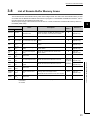
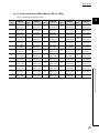
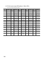
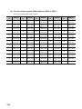
List of Remote Buffer Memory Areas
This section lists the remote buffer memory areas of the bridge module. The data in the remote buffer memory is read
and written with the REMFR and REMTO instructions of a program. For the REMFR and REMTO instructions, refer to
the user's manual for the master/local module used.
When the power supply of the module is turned off then on or reset, the data in the remote buffer memory returns to
the default (initial value).
Address
Name
Decimal
Hexadecimal
0 to 127
0 to 7FH
CC-Link parameter
information area
128 to
223
80H to DFH
System area
224 to
351
E0H to 15FH
352 to
479
Description
Read/
Write*1
Reference
Stores the information (parameter) on the bridge
module to perform the data link with the CC-Link
remote I/O station and remote device station.
R
-
-
CC-Link remote input (RX)
Stores the input status from the CC-Link remote
station.
R
Page 99,
Appendix 2 (2)
160H to
1DFH
CC-Link remote output
(RY)
Stores the output status of the CC-Link remote
station.
W
Page 100,
Appendix 2 (3)
480 to
735
1E0H to
2DFH
CC-Link remote register
(RWw)
Stores the transmitted data to the CC-Link
remote station.
W
Page 101,
Appendix 2 (4)
736 to
991
2E0H to
3DFH
CC-Link remote register
(RWr)
Stores the received data from the CC-Link
remote station.
R
Page 102,
Appendix 2 (5)
992 to
1503
3E0H to
5DFH
System area
1504 to
1535
5E0H to
5FFH
CC-Link link special relay
Stores the status of the data link of CC-Link.
1536 to
2047
600H to
7FFH
CC-Link link special
register
Stores the status of the data link of CC-Link.
2048 to
32767
800H to
7FFFH
System area
32768 to
33023
8000H to
80FFH
Module monitor/control
area
33024 to
35327
8100H to
89FFH
System area
R/W (only
the first 32
points can
be written)
-
-
Stores the remote READY, an error code, and a
warning code of the bridge module.
The areas are also used for a error clear request.
R/W
-
-
Page 98,
Appendix 2 (1)
-
Page 103,
Appendix 2 (6)
Page 108,
Appendix 2 (7)
Page 114,
Appendix 2 (8)
-
Shows whether the data can be read or written from/to the program.
R: Readable
W: Writable
31
3.8 List of Remote Buffer Memory Areas
*1
-
3
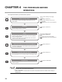
CHAPTER 4
THE PROCEDURE BEFORE
OPERATION
This chapter describes the procedure before operation.
Checkbox
Station number setting
Set the station numbers of the bridge module and the CC-Link
remote station.
Installation
Station number setting for the bridge
module
Page 37, Section 6.1
Station number setting for the CC-Link
remote station
Manual for the CC-Link remote station
Page 41, Section 6.3
Install the bridge module on a DIN rail.
Wiring
Connect a power supply, Ethernet cable, and CC-Link dedicated
cable to the bridge module.
Connect a power supply, CC-Link dedicated cable, and external
device to the CC-Link remote station.
Parameter setting for CC-Link IE Field Network
Wiring for the bridge module
Page 44, Section 6.4
Wiring for the CC-Link remote station
Manual for the CC-Link remote station
Page 53, Section 7.1
Connect the master station to GX Works2 to set the parameters of
CC-Link IE Field Network.
Parameter setting for CC-Link
Page 54, Section 7.2
Set the parameters of CC-Link with the switch of the bridge module.
Programming
Page 59, CHAPTER 8
Create a program.
To change the system, follow the procedure described below.
• Power off the system.
• Delete or add the CC-Link remote station and perform the procedure above from "Station number setting" to
"Programming".
32
CHAPTER 4 THE PROCEDURE BEFORE OPERATION
Memo
4
33
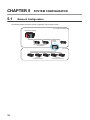
CHAPTER 5
5.1
SYSTEM CONFIGURATON
Network Configuration
The following diagram shows the network configuration using a bridge module.
CC-Link IE Field Network
Master/local module
Bridge
module
CC-Link IE Field Network
slave stations
CC-Link
CC-Link
remote I/O stations
34
CC-Link
remote device stations
CHAPTER 5 SYSTEM CONFIGURATON
5.2
Applicable Systems
(1) Applicable master station
Master stations that can be used are listed on the website of CC-Link Partner Association (CLPA).
Refer to the following.
http://www.cc-link.org/
Remark
Check the specifications of the master stations of each manufacturer before use.
5
(2) Applicable CC-Link module
The connectable stations are as follows:
• CC-Link Ver.1-compatible remote I/O station
• CC-Link Ver.1-compatible remote device station
The stations other than listed above cannot be connected.
(3) Ethernet cable
For the specifications of the Ethernet cable, refer to the following.
User's manual for the master/local module used
(4) CC-Link dedicated cable
Use a Ver.1.10-compatible CC-Link dedicated cable.
cable are used.
For the specifications of a Ver.1.10-compatible CC-Link dedicated cable and contact information, refer to the
following website.
http://www.cc-link.org/
Remark
Refer to "CC-Link Cable Wiring Manual" issued by CC-Link Partner Association.
(5) Supported software package
GX Works2 is required for setting and diagnosing a bridge module.
Software
Version
GX Works2
Version 1.98C or later
35
5.2 Applicable Systems
Performance of CC-Link cannot be guaranteed when cables other than a Ver.1.10-compatible CC-Link dedicated
5.3
Precautions
This section describes the precautions for the system configuration.
(1) CC-Link diagnostics
The CC-Link remote station connected to a bridge module cannot be diagnosed.
To check the status of CC-Link, use the remote buffer memory of the bridge module.
To acquire the remote buffer memory of the bridge module, a sequence program for accessing the remote buffer memory of
the bridge module is required.
36
CHAPTER 6 INSTALLATION AND WIRING
CHAPTER 6
INSTALLATION AND WIRING
This chapter describes the installation and wiring of the bridge module.
6.1
6.1.1
Station Number Setting
Station number setting of the bridge module
(1) Setting method
Set the station number with the rotary switch on the front of the module. The setting value of the station number
becomes effective when the module is powered on. Thus, set the station number while the module is powered
off.
• The hundreds and tens places of the station number are set with x10.
• The ones place of the station number is set with x1.
6
Ex. To set the station number to 115, set the switch as shown below.
Set the station number from 1 to 120. When a value outside the range of 1 to 120 is set, an error occurs and the
D LINK LED on the CC-Link IE Field Network side will not turn on.
37
6.1 Station Number Setting
6.1.1 Station number setting of the bridge module
(2) Setting range
6.1.2
Station number setting of a CC-Link remote station
(1) Setting method
For details on the station number setting of a CC-Link remote station, refer to the manual for each module.
(2) Detection of a station number in use error
A station number in use error of a bridge module is detected for a station number other than a start station
number.
If a station number in use error is detected, the ERR.LED on the CC-Link side flashes and the status is stored in
Station number in use status (address: 698H to 69BH).
Even if there is an error, data link is performed with normal stations.
After correcting the station number setting, turn off then on or reset the power supply of the bridge module to turn
off the ERR.LED on the CC-Link side and clear the data stored in Station number in use status (address: 698H to
69BH).
Remote device station (station No.1)
(4 stations occupied)
Station Station Station Station
No.1
No.2
No.3
No.4
The same
station No.
Remote device station (station No.4)
(2 stations occupied)
Station Station
No.4
No.5
If the start station numbers are the same, a station number in use error is not detected.
Check if the station number of the station with a data link error is used for another station with Other stations data
link status (address: 680H to 683H).
Ex. Between a remote device station (station number 1 with 4 stations occupied) and a remote device station
(station number 1 with 2 stations occupied)
A station number in use error is not detected in the following case.
Correct station numbers
of the remote device station
Remote device station
Station Station Station Station
No.1
No.2
No.3
No.4
The same start
station No.
Remote device station
Station Station
No.1
No.2
Incorrect station numbers
of the remote device station
38
Station Station
No.5
No.6
CHAPTER 6 INSTALLATION AND WIRING
6.2
6.2.1
Installation Environment and Installation Position
Installation environment
(1) Installation location
Do not install the bridge module to the place where:
• Ambient temperature is outside the range of 0 to 55°C;
• Ambient humidity is outside the range of 5 to 95% RH;
• Condensation occurs due to rapid temperature change;
• Corrosive gas or combustible gas is present;
• Conductive powder such as dust and iron powder, oil mist, salinity, or organic solvent is filled;
• The bridge module is exposed to direct sunlight;
• A strong electric field or strong magnetic field is generated; and
• The bridge module is subject to vibration and shock.
6
(2) Installation surface
Install the bridge module on a flat surface. When the installation surface is uneven, excessive force is applied to
the printed-circuit board, causing a failure.
6.2.2
Installation position
When installing the bridge module in a control panel, provide clearance of 60mm or longer between the module and
the sides of the control panel or neighboring modules to ensure good ventilation and to facilitate a module change.
6.2 Installation Environment and Installation Position
6.2.1 Installation environment
60mm
or longer
60mm
or longer
60mm
or longer
60mm
or longer
39
6.2.3
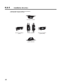
Installation direction
A bridge module can be installed in six directions.
Use a DIN rail to install the module.
Downward installation
DIN rail
Horizontal installation
(basic)
Vertical installation
Upward installation
40
Horizontal installation
(upside down)
CHAPTER 6 INSTALLATION AND WIRING
6.3
Installation
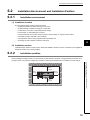
6.3.1
Mounting a module on a DIN rail
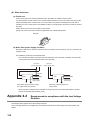
An example of the use of the DIN rail stopper is described in the following procedure. Fix the module according to the
manual of the DIN rail stopper used.
(1) Mounting procedure
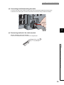
This section describes how to mount the bridge module on a DIN rail.
1.
2.
Push in the DIN rail hook of the module until it
clicks.
3.
Loosen the screw on the DIN rail stopper.
4.
Hitch the bottom hook of the DIN rail stopper to the
bottom of the DIN rail.
Hitch the hook according to the orientation of the arrow
on the front of the stopper.
6
6.3 Installation
6.3.1 Mounting a module on a DIN rail
Hook
Hitch the upper hook of the module to the top of the
DIN rail.
Hook
Hitch the hook to
bottom of the DIN rail
41
Hitch the hook to
top of the DIN rail
5.
Hitch the upper hook of the DIN rail stopper to the
top of the DIN rail.
6.
Slide the DIN rail stopper up to the left edge of the
module.
7.
Hold the DIN rail stopper in the orientation opposite
to the arrow inscribed on the stopper and tighten
the screw with a driver.
8.
Install the DIN rail stopper on the right side of the
module in the same procedure.
Install the stopper upside down on the right side.
DIN rail
stopper
DIN rail
stopper
DIN rail
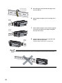
stopper
Do not slide the module from the edge of the DIN rail. Doing so may damage the metal part located on the back of the
module.
42
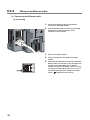
CHAPTER 6 INSTALLATION AND WIRING
(2) Removal procedure
1.
Remove the DIN rail stopper.
Remove the module in the reverse manner of (1).
2.
Remove the module from the DIN rail by pulling the
lower part of the module closer while pushing down
the DIN rail hook with a slotted screwdriver.
(3) Applicable DIN rail model (compliant with IEC 60715)
• TH35-7.5Fe
• TH35-7.5Al
6
(4) Interval between DIN rail mounting screws
Tighten the screws at intervals of 200mm or less.
(5) DIN rail stopper
Use a stopper that is attachable to a DIN rail.
6.3 Installation
6.3.1 Mounting a module on a DIN rail
43
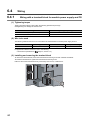
6.4
6.4.1
Wiring
Wiring with a terminal block for module power supply and FG
(1) Tightening torque
Tighten the terminal block screws within the following specified torque range.
Overtightening can damage the module case.
Screw type
Tightening torque range
Terminal block mounting screw (M2.5 screw)
0.2 to 0.3N·m
Terminal screw (M2.5 screw)
0.5 to 0.6N·m
(2) Wire to be used
The following table lists the wire to be connected to the terminal block for module power supply and FG.
Diameter
Type
Material
Temperature rating
20 to 16 AWG
Stranded
Copper
75°C or more
For applicable solderless terminals, refer to the following.
• Performance Specifications (
Page 21, Section 3.2 )
(3) Installing and removing the terminal block
To remove the terminal block, loosen the terminal block mounting screw with a slotted screwdriver.
To install the terminal block, tighten the terminal block mounting screw.
Failure to secure the terminal block may cause drop, short-circuit, or malfunction.
44
CHAPTER 6 INSTALLATION AND WIRING
(4) Connecting and disconnecting the cable
To connect the cable, insert it with the cable fixing screw loosened and tighten the terminal screw.
To disconnect the cable, pull it out with the terminal screw loosened using a slotted screwdriver.
6
(5) Processing method of the cable terminal
Strip the cable about 10mm from the edge.
To use a bar solderless terminal, connect it to the stripped part.
ble
Ca
ou
0m
m
6.4 Wiring
6.4.1 Wiring with a terminal block for module power supply and FG
Ar
1
nd
45
6.4.2
Wiring of an Ethernet cable
(1) Connecting the Ethernet cable
(a) Connecting
1.
Power off the bridge module and the devices
connected to the bridge module.
2.
Push the Ethernet cable connector into the bridge
module until it clicks. Pay attention to the
orientation of the connector.
3.
4.
Power on the bridge module.
5.
Check that the LINK LED on the port into which the
Ethernet cable is connected is on. It may take a few
seconds for the LINK LED to turn on after the
module is powered on. Normally, it turns on in a few
seconds. If the LINK LED does not turn on, refer to
the troubleshooting section and take a corrective
Power on the devices connected to the bridge
module.
action. (
46
Page 84, Section 9.6.2 (7))
CHAPTER 6 INSTALLATION AND WIRING
● PORT1 and PORT2 connectors need not to be distinguished. When only one connector is used in the star topology,
either PORT1 or PORT2 can be used.
Either one can be used.
● When two connectors are used in the line topology or ring topology, an Ethernet cable can be connected to the PORT1
and PORT2 connectors in any combination. For example, a cable can be connected between PORT1s or between
PORT1 and PORT2.
Connection between
PORT1s or PORT2s
Connection between
PORT1 and PORT2
6
1.
2.
Power off the module.
Unplug the Ethernet cable while pinching the latch
of the cable.
47
6.4 Wiring
6.4.2 Wiring of an Ethernet cable
(b) Disconnecting
(2) Precautions
This section describes precautions on the wiring for CC-Link IE Field Network.
(a) Laying Ethernet cables
• Place the Ethernet cable in a duct or fix the cable by clamping it. If not, dangling cable may swing or
inadvertently be pulled, resulting in damage to the module or cables or malfunction due to poor contact.
• Do not touch the core of the connector of the cable or the module, and protect it from dirt and dust. If any oil
from hands or any dirt or dust sticks to the core, it can increase transmission loss, causing data link to fail.
• Check the following:
• Is any Ethernet cable disconnected?
• Is any Ethernet cable shorted?
• Are the connectors securely connected?
(b) Broken cable latch of the Ethernet cable
Do not use an Ethernet cable with broken latches. Doing so may cause the cable disconnection or malfunction.
(c) Connecting and disconnecting the Ethernet cable
Hold the connector part when connecting and disconnecting the Ethernet cable. Pulling the cable with
connected to the module may result in damage to the module or cable or malfunction due to poor contact.
(d) Connectors without Ethernet cables connected
To prevent dust from entering the module, attach the included connector cover.
(e) Maximum station-to-station distance of the Ethernet cable (maximum cable length)
The maximum station-to-station distance is 100m. However, the distance may become shorter depending on
the operating environment of the cable. For details, contact the manufacturer of the cable used.
(f) Bend radius of the Ethernet cable
There are restrictions on the bend radius of the Ethernet cable. Check the bend radius in the specifications of
the Ethernet cable used.
48
CHAPTER 6 INSTALLATION AND WIRING
6.4.3
Wiring of a CC-Link dedicated cable
This section describes the wiring of the terminal block for CC-Link.
(1) Preparation before wiring
(a) Available cable
For the bridge module, use a Ver.1.10-compatible CC-Link dedicated cable.
If cables other than a Ver.1.10-compatible CC-Link dedicated cable are used, normal data transmission is not
guaranteed.
(b) Connection order
Cables do not need to be connected in order of station number.
(c) Terminating resistor to be used
Always connect included terminating resistors (110W, 1/2W (brown, brown, brown)) to the modules at both
ends of the CC-Link system.
6
(2) Wiring method
(a) Wiring diagram
There are no restrictions on the connection location of the bridge module. (Cables do not need to be connected
in order of station number.)
Terminating
resistor
DA
DB
(Blue)
(White)
(White)
(Yellow)
(Yellow)
SLD
CC-Link dedicated cable
DA
DB
DG
SLD
(Blue)
(Blue)
(White)
(White)
(Yellow)
(Yellow)
CC-Link dedicated cable
FG
FG
DA
DB
Terminating
resistor
6.4 Wiring
6.4.3 Wiring of a CC-Link dedicated cable
DG
(Blue)
DG
SLD
FG
(b) Actual wiring
Terminating
resistor
(Yellow)
(White)
(Blue)
49
● Connect a terminating resistor between DA and DB.
● Connect the shielded wire of a CC-Link dedicated cable to SLD of each module and ground both ends via FG with a
ground resistance of 100 or less. SLD and FG are connected inside the module.
● Star topology can not be used. However, T-branch connection can be used. (
Page 51, Section 6.4.3 (5))
(3) Terminal block for CC-Link
(a) Solderless terminal
For wiring, use the applicable solderless terminal and wire specified in the following table and attach them in an
applicable tightening torque. Use UL-listed solderless terminals. For processing, use a tool recommended by
manufacturers of solderless terminals.
Sleeved solderless terminals cannot be used.
Solderless terminal
Wire
Model
Applicable tightening
torque
Diameter
Type
Material
Temperature
rating
1.25-3
0.42 to 0.58N·m
22 to 16 AWG
Stranded
Copper
60°C or more
(b) Screw and tightening torque
Tighten the terminal block screws within the following specified torque.
Overtightening can damage the module case.
Screw type
Tightening torque
Terminal block screw (M3 screw)
0.43 to 0.57N·m
Terminal block mounting screw (M3.5 screw)
0.68 to 0.92N·m
● Prevent oil from adhering on the terminals and screws. Failure to do so may damage the screws.
● When inserting two solderless terminals, insert them back-to-back. Otherwise the screw cannot be tightened and it may
damage the screw.
● Tighten the terminal screws with an appropriate driver. Otherwise it may damage the screw.
(4) Wiring check
After wiring the master station, the bridge module, and the CC-Link remote station, check that the CC-Link
remote station is turned on/off by turning on/off the device of the master station.
50
CHAPTER 6 INSTALLATION AND WIRING
(5) T-branch connection
This section describes the method to configure the T-branch connection of the CC-Link system.
(a) T-branch system configuration
The following figure shows the system configuration for the T-branch connection.
(T-branch terminal
block/connector)
(Main line)
Remote I/O station/
remote device station
Bridge
module
Terminating resistor
(DA-DB)
(Branch line)
Remote I/O station/
remote device station
(Branch line)
Remote I/O station/
remote device station
Remote I/O station/
remote device station
Remote I/O station/
remote device station
(Branch
line)
(Branch
line)
Terminating resistor
(DA-DB)
Remote I/O station/
remote device station
6
Remote I/O station/
remote device station
Remote I/O station/
remote device station
Remote I/O station/
remote device station
Remote I/O station/
remote device station
Remote I/O station/
remote device station
Up to six stations can be connected.
Up to six stations can be connected.
6.4 Wiring
6.4.3 Wiring of a CC-Link dedicated cable
The number of branch lines depends on the length of each branch line and
the total length of all the branch lines.
51
(b) Communication specifications list of T-branch connection
The following table lists the communication specifications for the T-branch connection.
For the communication specifications not listed in the following table, refer to the performance specifications.
(
Page 21, Section 3.2)
Item
Specifications
Transmission speed
Maximum length of the main
line
156kbps
100m
500m
Maximum length of the branch
line
10M/5M/2.5Mbps cannot be used.
Cable length between the terminating resistors.
The cable length of T-branch (length of the branch
line) is not included.
8m
Overall branch line length
Total cable length per branch
50m
Maximum number of modules
on the branch line
Connection cable
Remarks
625kbps
200m
Total length of all branch cables
Total number of connected modules is in
accordance with the CC-Link specifications.
6 modules/branch
Ver.1.10-compatible CC-Link dedicated cable
Ver.1.10-compatible CC-Link dedicated cables
made by different manufacturers can be used in
combination.
• Terminal block
Commercially available terminal block
• Connector
T-branch terminal
block/connector
FA sensor connector NECA4202
(IEC947-5-2) or equivalent is recommended.
Avoid peeling the sheath of the cable on the main
line side whenever possible.
(NECA: Nippon Electric Control Equipment
Industries Association Standards)
Ver.1.10-compatible CC-Link dedicated cable (Terminating resistors of 110 are used.)
Maximum length of the main
line, length between two Tbranch lines, and station-tostation distance
Transmission
speed
Maximum
length of
the main
line
625kbps
100m
156kbps
500m
Length
between two
T-branch
lines
Distance between remote
I/O stations or remote device stations
No limitation
30cm or more
Maximum length of the main line (the branch line length excluded)
The length between two T-branch lines
Terminating
resistor
Bridge
module
R
R
R
R
Terminating
resistor
R
R
R
R
R
R
R
(Branch line length: 8m or shorter)
52
R
R
R
R
R
R
(Branch line length: 8m or shorter)
R
: Represents a remote I/O station or remote device station
CHAPTER 7 VARIOUS SETTINGS
CHAPTER 7
VARIOUS SETTINGS
This chapter describes the various setting methods of the bridge module.
7.1
Parameter Settings for CC-Link IE Field Network
To use the bridge module, set the number of points and assignment of the link device in the CPU module of the master
station.
This manual describes the settings of the bridge module. For the settings of network and refresh parameters, refer to
the user's manual for the master/local module used.
(1) Setting procedure
1.
Display the "CC IE Field Network Configuration Setting" window.
• When the master/local module is the QJ71GF11-T2
Project window
[Parameter]
[Network Parameter]
[Ethernet/CC IE/MELSECNET]
button
7
• When the master/local module is the LJ71GF11-T2
Project window
[Parameter]
[Network Parameter]
[Ethernet/CC IE Field]
7.1 Parameter Settings for CC-Link IE Field Network
2.
button
Enter the setting for the bridge module.
Enter the following values for the setting of the bridge module.
Setting item
Description
Station number
Set the station number for the bridge module.
Station type
Select "Intelligent Device Station".
RX/RY setting
Number
of points
32 points x last station number on the CC-Link side (including the number of occupied
stations)
RWr/RWw setting
Number
of points
4 points x last station number on the CC-Link side (including the number of occupied
stations) + 16 points
3.
Click the
button.
53
7.2
Parameter Settings for CC-Link
This section describes the settings for CC-Link.
Follow the procedures below to set CC-Link.
CC-Link remote station detection
Page 55, Section 7.2 (1)
Execute the automatic CC-Link startup so that the bridge module
detects the CC-Link remote station.
Parameter saving
Page 56, Section 7.2 (2)
Save the information of the CC-Link remote station as parameters into
the bridge module. Then restart CC-Link.
Communication status checking
Execute a line test in CC-Link to check the communication status.
54
Page 58, Section 7.2 (3)
CHAPTER 7 VARIOUS SETTINGS
(1) Identification of a CC-Link remote station
The automatic CC-Link startup enables the bridge module to recognize the CC-Link remote stations and start
CC-Link only by powering on the module.
After executing the automatic CC-Link startup, set the parameters with the slave station information saving.
(
Page 56, Section 7.2 (2))
Startup mode switch
Master/local module
The automatic CCLink startup can be
executed with the
startup mode switch
set to AUTO.
CC-Link IE Field Network
CC-Link IE Field Network slave stations
Bridge module
CC-Link
7
Station No.1
Station No.2
Station No.3
Station No.4
Station No.5
Station No.6
remote I/O station remote I/O station remote device station remote I/O station remote device station remote I/O station
Station
Connected station
not connected
Connected stations
Station No.64
remote I/O station
Stations not connected
The number of connected stations: 64
7.2 Parameter Settings for CC-Link
Default setting with the
automatic CC-Link startup
(a) Operating procedure
This section describes the procedures for the automatic CC-Link startup.
Execute this function after completing all the wiring.
1.
2.
3.
4.
5.
6.
Set the startup mode switch of the bridge module to AUTO.
Power on the module of the CC-Link remote station.
Power on the bridge module.
The RUN LED and L RUN LED on the CC-Link side turn on.
Power on the master station.
CC-Link is started and the data is refreshed.
● Always power on the CC-Link remote station module first. If the bridge module is powered on first, the CC-Link remote
station is not recognized in the automatic CC-Link startup.
● If the station is not connected to the CC-Link remote station or not recognized upon automatic CC-Link startup, such
station number is recognized as an unconnected station. Accordingly, when 64 CC-Link remote stations are not
connected, the ERR.LED on the CC-Link side flashes. To check whether a connecting station is performing data link, use
Data link status of other stations on CC-Link (RWr8 to RWrB).
● Always perform the line test to all the stations whenever the system is changed due to the module replacement or other
reasons after performing the automatic CC-Link startup.
If a station with the start station number used for another station is returned, a station already performing data link (only a
station having a station number in use error) may be disconnected.
55
(b) Precautions
• If the automatic CC-Link startup is executed in the following conditions of the CC-Link remote station, the
bridge module cannot recognize the CC-Link remote station, resulting in a data link failure.
Item
Description
Transmission
speed mismatch
The transmission speed set for the bridge module
is different from that for the CC-Link remote
station.
Error in number
of connected
modules
The total number of CC-Link remote stations or
connected modules is outside of the specifications
range.
Station number in
use error
The same station number is used for multiple CCLink remote stations.
Action
Set the transmission speed of the bridge module
and the CC-Link remote station properly.
(
Page 17, CHAPTER 2)
Adjust the number of CC-Link remote stations and
connected modules within the range of the
specifications.
(
Page 22, Section 3.2 (3))
Set the appropriate station number for the CC-Link
remote station.
• Check the cable for disconnection, short circuit,
incorrect wiring, poor contact, and usage not
meeting the specifications (transmission
Cable error
The CC-Link dedicated cable has an error.
distance, station-to-station distance, coexistence
of different types of cables, and FG connection).
• Check if a transmission cable other than a CCLink dedicated cable is used.
• Temporary error invalid stations cannot be used with data link established through the automatic CC-Link
startup. Start CC-Link with the slave station information saving function.
(2) Saving parameters
The information of a slave station performing data link through the automatic CC-Link startup is stored in the flash
ROM inside a bridge module using the slave station information saving function.
If the startup mode switch of a bridge module is set to PRM with the slave station information saved, the
parameters are set based on the saved data. Then CC-Link is started, and data link is performed.
(a) Operating procedure
The following is a procedure for saving slave station information.
1.
2.
Start CC-Link using the automatic CC-Link startup function. (
3.
The bridge module is reset and data link is started by executing the automatic CC-Link startup
again.
4.
5.
Set the startup mode switch of the bridge module to PRM.
6.
7.
The RUN LED and L RUN LED on the CC-Link side turn on.
Page 55, Section 7.2 (1) (a))
Hold the startup mode switch in the SET position until the CC-Link RUN LED of the bridge module
turns off (about five seconds).
Slave station information is saved in the flash ROM inside the bridge module.
The bridge module is reset and the parameters are set based on the saved slave station
information.
CC-Link is started.
If the startup mode switch of the bridge module is set to PRM when the power supply of the module is
turned off then on, the parameters are set based on the saved slave station information and CC-Link is
started.
● When the slave station information saving function is executed, the remote station having the largest station number
among connected stations is recognized as the last station.
The unconnected stations having a smaller station number than the last station are set as reserved stations in the
parameter when the slave station information is saved.
56
CHAPTER 7 VARIOUS SETTINGS
(b) Parameters
The network parameters of CC-Link are set as listed below.
Item
Description
Setting value
Mode
Set the mode for the bridge module.
Remote Net (Ver.1 Mode)
Total Module Connected
Set the number of CC-Link remote stations
connected.
Based on the actual connection
Retry Count
Set the number of retries to be performed upon a
communication error.
3 times
Automatic Reconnection
Station Count
Set the number of CC-Link remote stations that can
be returned to the network with one link scan from
the disconnection due to a communication error or
other factors.
1 station
PLC Down Select
Specify whether to stop or continue data link when
a stop error occurs in the CPU module of the
master station.
Stop
Data Link Faulty Station
Setting
Specify whether to clear or hold the input data from
the data link faulty station.
Clear the input data
Case of CPU STOP Setting
Specify whether to refresh or compulsorily clear the
data output (transmitted) to the CC-Link remote
stations when the CPU module of the master
station is stopped.
Refresh
7
Only when CC-Link is started using the slave station information saving function, a temporary error invalid station can be set
using the remote buffer memory. (
Page 106, Appendix 2 (6) (a))
7.2 Parameter Settings for CC-Link
57
(3) Check of communication (line test)
This section describes the line test of CC-Link.
For the line test of CC-Link IE Field Network, refer to the following.
User's manual for the master/local module used
1.
Check the following before executing the line test.
• Check that the startup mode switch of the bridge
module is set to AUTO or PRM.
• Check that all the CC-Link remote stations are
connected using CC-Link dedicated cables.
• Check that the module is connected with the master
station.
2.
Set the station number setting switch of the bridge
module according to the network parameter of CCLink IE Field Network.
3.
Set the transmission speed/mode setting switch of
the bridge module to the range of 5 to 9.
When setting the switch to 5 to 9, set the same
transmission speed as that of the system operation.
(
Page 17, CHAPTER 2)
4.
Turn the power supply off then on in the order of the
CC-Link remote station, the bridge module, and the
master station.
5.
The line test starts.
The MST LED flashes during the line test.
6.
The L RUN LED or the MST LED turns on when the
line test is completed.
• Test completed
The L RUN LED turns on and the MST LED flashes.
The station number which performs data link
successfully with the CC-Link remote station is
stored in Line test 1 result (address: 6B4H to 6B7H).
Test in execution
: On
: Flashing
: Off
Normal completion
: On
: Flashing
: Off
Abnormal end
: On
: Flashing
: Off
• Test not completed (all stations failed)
The MST LED turns on and the ERR. LED on the
CC-Link side flashes.
The error code is stored in Line test result (address:
6B8H). (
Page 76, Section 9.5)
To obtain Line test 1 result (address: 6B4H to 6B7H) or Line test result (address: 6B8H), a sequence program for accessing
the remote buffer memory of the bridge module is required.
58
CHAPTER 8 PROGRAMMING
CHAPTER 8
PROGRAMMING
This chapter describes the programming of the bridge module.
The program of the bridge module is written to the CPU module of the master station.
8.1
Precautions for Programming
(1) Cyclic transmission program
For a cyclic transmission program, interlock the link special relay (SB) and the link special register (SW) of the
master/local module with the remote register (RWr) of the bridge module.
• Data link status (own station) (SB0049)
• Data link status (each station) (SW00B0 to SW00B7)
• CC-Link operating status (RWr4 to RWr5) (
Page 96, Appendix 1 (4))
• Data link status of other stations on CC-Link (RWr8 to RWrB) (
Page 97, Appendix 1 (5))
For the link special relay (SB) and link special register (SW) of CC-Link IE Field Network, refer to the following.
User's manual for the master/local module used
8
8.1 Precautions for Programming
59
(a) Interlock program example
This section describes an interlock program example when the link devices are set as follows.
Link device RWr
in which the remote buffer memory is
CPU device assigned with the refresh
parameter
stored
CC-Link side
RWr4
W4
RWr8 to RWrB
W8 to WB
The following table lists the devices used by a user in the program example.
Device
Description
SB0049
Data link status of the own station on the CC-Link IE Field Network side
SW00B0.0
Data link status of each station on the CC-Link IE Field Network side (station number 1)
W4.0
CC-Link error
W4.1
Data link status of the own station on the CC-Link side
W4.F
CC-Link ready
W8.0
Data link status of other stations on the CC-Link side (station number 1)
Ex. Interlock example
Program of communications with the station No.1 (bridge module) on CC-Link IE Field
Program of communications with the station No.1 on CC-Link
60
CHAPTER 8 PROGRAMMING
(2) Transient transmission program
For a transient transmission program, interlock the link special relay (SB) with the link special register (SW) of the
master/local module.
• Baton pass status (own station) (SB0047)
• Baton pass status (each station) (SW00A0 to SW00A7)
For the link special relay (SB) and link special register (SW) of CC-Link IE Field Network, refer to the following.
User's manual for the master/local module used
(a) Interlock program example
The following table lists the devices that are used by a user in the program example.
Device
Description
SB0047
Baton pass status of the own station on the CC-Link IE Field Network side
SW00A0.0
Baton pass status of each station on the CC-Link IE Field Network side (station number 1)
Ex. Interlock example
Startup contact
Dedicated instruction for the station No.1
8
8.1 Precautions for Programming
61
8.2
Example of Communications with CC-Link Remote
Stations
This section describes an example of communications with CC-Link remote stations using the following system
configuration.
8.2.1
System configuration example
(1) System configuration
Power supply module (Q62P)
CPU module (Q10UDHCPU)
Master/local module (QJ71GF11-T2)
Bridge module (NZ2GF-CCB)
CC-Link
IE Field Network
(Network No.1)
00 to 1F
Station No.1
CC-Link
Remote I/O station
(1 station occupied)
(AJ65SBTB1-32DT2)
Remote device station
(3 stations occupied)
(AJ65VBTCU-68ADVN)
Station No.1
RY10 lamp
RX0 pressing button
Station No.2
62
CHAPTER 8 PROGRAMMING
(2) Link device assignment
CC-Link IE Field Network
CC-Link
CPU module
Master/local module
Bridge module
(station No.1)
Remote I/O station
(station No.1)
(1 station occupied)
Remote device station
(station No.2)
(3 stations occupied)
Device X
X1000 to X101F
Remote input RX
RX00 to RX1F
Remote input RX
RX00 to RX1F
Remote input RX
RX00 to RX1F
Remote input RX
X1020 to X107F
RX20 to RX7F
RX20 to RX7F
Device Y
Y1000 to Y101F
Remote output RY
RY00 to RY1F
Remote output RY
RY00 to RY1F
Y1020 to Y107F
RY20 to RY7F
RY20 to RY7F
Device W
Remote register RWr
Remote register RWr
W0 to WF
RWr0 to RWrF
RWr0 to RWrF
W10 to W13
RWr10 to RWr13
RWr10 to RWr13
W14 to W1F
RWr14 to RWr1F
RWr14 to RWr1F
Device W
Remote register RWw
Remote register RWw
W1000 to W100F
RWw0 to RWwF
RWw0 to RWwF
W1010 to W1013
RWw10 to RWw13
RWw10 to RWw13
W1014 to W101F
RWw14 to RWw1F
RWw14 to RWw1F
RX00 to RX5F
Remote output RY
RY00 to RY1F
Remote output RY
RY00 to RY5F
Remote register RWr
Data such as the
operating status of
the bridge module
RWr0 to RWrB
Remote register RWw
Data such as
the settings of
the bridge module
8
RWw0 to RWwB
8.2 Example of Communications with CC-Link Remote Stations
8.2.1 System configuration example
63
8.2.2
Setting of CC-Link IE Field Network
Connect GX Works2 to the master station and set parameters for CC-Link IE Field Network.
1.
Create a project of GX Works2.
Select "QCPU (Q mode)" for "PLC Series" and select "Q10UDH" for "PLC Type".
[Project]
2.
[New]
Display the network parameter setting window and configure the setting as follows.
Project window
[Parameter]
[Ethernet/CC IE/MELSECNET]
64
[Network Parameter]
CHAPTER 8 PROGRAMMING
3.
Display the CC IE Field Network configuration setting window and configure the setting as follows.
button
4.
Display the refresh parameter setting window and configure the setting as follows.
button
8
Write the set parameters to the CPU module of the master station and reset or power off then on
the CPU module.
[Online]
[Write to PLC]
RESET
or Power OFF
ON
Use the default values for parameters other than those shown in the program example above. For parameters, refer to the
following.
User's manual for the master/local module used
65
8.2 Example of Communications with CC-Link Remote Stations
8.2.2 Setting of CC-Link IE Field Network
5.
8.2.3
Setting of CC-Link
To start CC-Link, use the automatic CC-Link startup function and the slave station information saving function.
1.
2.
Power on the module of the CC-Link remote station.
3.
4.
Power on the bridge module.
Set the startup mode switch of the bridge module to AUTO.
Hold the startup mode switch in the SET position (for about five seconds) until the CC-Link RUN
LED of the bridge module turns off.
5.
66
Set the startup mode switch of the bridge module to PRM.
CHAPTER 8 PROGRAMMING
8.2.4
Program example
This section describes a program example. Write a program to the CPU module of the master station.
(1) Devices used in the program
(a) Link special relay (SB) and link special register (SW)
Device
SB0049
Description
Data link status of the own station
on the CC-Link IE Field Network side
Device
SW00B0.0
Description
Data link status of each station on the CCLink IE Field Network side (station number 1)
(b) Devices used by a user
Device
X1000
X1020
Description
X0 input signal from the CC-Link side (station number 1)
Remote input RX0 (CH1 A/D conversion completed flag) on the CC-Link side
(station number 2)
X1038
Remote input RX18 (Initial data processing request flag) on the CC-Link side (station number 2)
X1039
Remote input RX19 (Initial data setting completion flag) on the CC-Link side (station number 2)
X103A
Remote input RX1A (Error flag) on the CC-Link side (station number 2)
X103B
Remote input RX1B (Remote READY) on the CC-Link side (station number 2)
Y1010
Y10 output signal to the CC-Link side (station number 1)
Y1038
Remote input RX1B (Remote READY) on the CC-Link side (station number 2)
Y1039
Remote output RY19 (Initial data setting request flag) on the CC-Link side (station number 2)
Y103A
Remote output RY1A (Error reset request flag) on the CC-Link side (station number 2)
N0
Nesting on the CC-Link IE Field Network side
N1
Nesting on the CC-Link side (station number 1)
Nesting on the CC-Link side (station number 2)
M0
Communication condition satisfied flag on the CC-Link IE Field Network side
M1
Communication condition satisfied flag on the CC-Link side (station number 1)
M2
Communication condition satisfied flag on the CC-Link side (station number 2)
M100
Initial settings change flag on the CC-Link side (station number 2)
M101
Error clear flag on the CC-Link side (station number 2)
W4.0
CC-Link error
W4.1
Data link status of the own station on the CC-Link side
W4.F
CC-Link ready
W8.0
Data link status of other stations on the CC-Link side (station number 1)
W8.1
Data link status of other stations on the CC-Link side (station number 2)
W14
Remote register RWr0 (CH1 Digital output value) on the CC-Link side (station number 2)
W1C
Remote register RWr8 (Error code) on the CC-Link side (station number 2)
W1014
W1015
W1017
W1019
Remote register RWw0 (A/D conversion enable/disable setting) on the CC-Link side
(station number 2)
Remote register RWw1 (CH1 to CH4 Input range setting) on the CC-Link side
(station number 2)
Remote register RWw3 (Averaging processing specification) on the CC-Link side
(station number 2)
Remote register RWw5 (CH2 Time average/count average setting) on the CC-Link
side (station number 2)
D500
CH1 Digital output value storage
D508
Error code storage
67
8.2 Example of Communications with CC-Link Remote Stations
8.2.4 Program example
N2
8
(2) Program example
Data link normal in the bridge module
Data link normal in the station No.1
on CC-Link
Lamp on
Data link normal in the station No.2
on CC-Link
A/D conversion enable/disable
specification (RWw0)
Input range setting (RWw1)
Average processing specification
(RWw3)
CH2 Time average/count average
setting (RWw5)
Initial data processing completion
flag (RY18) on
Initial data setting request flag
(RY19) on
A/D conversion enable/disable
specification (RWw0)
Input range setting (RWw1)
Initial data setting request flag
(RY19) on
Initial data processing completion
flag (RY18) off
Initial data setting request flag
(RY19) off
Read CH1 Digital output value
(RWr0).
Read Error code (RWr8).
Error reset request flag (RY1A) on
Error reset request flag (RY1A) off
If the bridge module does not respond to the master station for several link scans, such station is judged as a cyclic
transmission faulty station. Then the bit of the corresponding station turns on in Data link status (each station) (SW00B0 to
SW00B7).
68
CHAPTER 9 TROUBLESHOOTING
CHAPTER 9
9.1
TROUBLESHOOTING
9
Operation Upon Error
This section describes the status of a link device if a communication error occurs in the master station or the CC-Link
remote station during data link.
(1) When the status of the CPU module of the master station becomes STOP due
to an error (with data link continued)
Module
Remote input (RX)
Remote output (RY)
Remote register
(RWw)
Remote register
(RWr)
CPU module of the master station
Continue
Depends on the GX
Works2
setting
Continue
Hold
Bridge module
Continue
Clear
Continue
Hold
CC-Link remote I/O station
Continue
Clear
-
-
CC-Link remote device station
Continue
Clear
Continue
Continue
(2) When data link on CC-Link IE Field Network stops
Remote input (RX)
Remote output (RY)
Remote register
(RWw)
Remote register
(RWr)
CPU module of the master station
Depends on the GX
Works2
setting
Not output
Continue
Hold
Bridge module
Depends on the GX
Works2
setting
Not output
Continue
Hold
Depends on the
external signal
All points turn off.
-
-
*1
All points turn off.
*1
*1
CC-Link remote I/O station
CC-Link remote device station
*1
9.1 Operation Upon Error
Module
Error status defined by the CC-Link remote device station
(3) When the bridge module stops due to an error
Module
Remote input (RX)
Remote output (RY)
Remote register
(RWw)
Remote register
(RWr)
CPU module of the master station
• The receiving area for
the remote I/O station
having a
communication error
is cleared.
• The areas for remote
I/O stations having no
communication error
are continued.
Continue
The areas for remote I/O
stations having no
communication error are
continued.
The areas for remote I/O
stations having no
communication error are
continued.
Bridge module
CC-Link remote I/O station
CC-Link remote device station
-
-
-
-
Depends on the
external signal
All points turn off.
-
-
Continue
Continue
Continue
Continue
69
(4) When a communication error (such as power-off) occurs in a CC-Link remote
I/O station
Remote output (RY)
Remote register
(RWw)
Remote register
(RWr)
Continue
The areas for remote I/O
stations having no
communication error are
continued.
The areas for remote I/O
stations having no
communication error are
continued.
• The receiving area for
the remote I/O station
having a
communication error
is cleared.
• The areas for remote
I/O stations having no
communication error
are continued.
Continue
The areas for remote I/O
stations having no
communication error are
continued.
The areas for remote I/O
stations having no
communication error are
continued.
Depends on the
external signal
All points turn off.
-
-
Continue
Continue
Continue
Continue
Module
Remote input (RX)
CPU module of the master station
• The receiving area for
the remote I/O station
having a
communication error
is cleared.
• The areas for remote
I/O stations having no
communication error
are continued.
Bridge module
CC-Link remote I/O station
CC-Link remote device station
(5) When a communication error (such as power-off) occurs in a CC-Link remote
device station
Continue
• The receiving area for
the remote device
station having a
communication error
is held.
• The areas for remote
device stations
having no
communication error
are continued.
Continue
• The receiving area for
the remote device
station having a
communication error
is held.
• The areas for remote
device stations
having no
communication error
are continued.
CPU module of the master station
• The receiving area for
the remote device
station having a
communication error
is cleared.
• The areas for remote
device stations
having no
communication error
are continued.
Bridge module
• The receiving area for
a remote device
station having a
communication error
is cleared.
• The areas for remote
device stations
having no
communication error
are continued.
Continue
Continue*2
Continue*2
-
-
*1
*1
*1
*1
CC-Link remote device station
*1
*2
70
Remote register
(RWr)
Remote input (RX)
CC-Link remote I/O station
Remote output (RY)
Remote register
(RWw)
Module
Continue
Error status defined by the CC-Link remote device station
Continued regardless of the communication status of the CC-Link remote device station
CHAPTER 9 TROUBLESHOOTING
9.2
Troubleshooting Procedure
9
This section describes a procedure from identifying the cause of an error to taking a corrective action.
1.
Troubleshooting for CC-Link IE Field Network
Errors can be checked with the CC-Link IE Field Network diagnostics of GX Works2 connected to the
master station.
Identify the cause of an error and take a corrective action. (
2.
3.
Troubleshooting for errors occurring in the bridge module (
Page 72, Section 9.3)
Page 74, Section 9.4)
If data link cannot be performed even after the troubleshooting above is performed, follow the
troubleshooting procedures below.
• Checking the LEDs (
Page 82, Section 9.6)
• Troubleshooting by Symptom (
Page 87, Section 9.7)
9.2 Troubleshooting Procedure
71
9.3
CC-Link IE Field Network Diagnostics
With this function, whether a network error has occurred can be checked on GX Works2 connected to the master
station.
(1) How to use
1.
2.
Connect GX Works2 to the master station.
Start the CC IE Field Network diagnostics from the menu of GX Works2.
[Diagnostics]
[CC-Link IE Field Diagnostics]
1
3
2
4
5
Diagnostics item
1
Display of the network map
and error status
2
Display of the status of the
selected station and error
details
5
72
Reference
The status of CC-Link IE Field Network can be checked.
If an error or warning occurs in the bridge module, an icon appears.
The communication status of the station selected in "Networks Status" can be
checked.
The LEDs in the upper row of the module diagram shows LEDs on the CC-Link IE
Field Network side and those in the lower row are LEDs on the CC-Link side.
Communication Test
The route and establishment of transient communications from the connected
station to the destination station can be checked.
IP Communication Test
This function cannot be used for the bridge module.
Cable Test
The cable connection status between the tested station and the device
connected to the port of the tested station can be checked.
Link Start/Stop
Data link can be started or stopped.
3
4
Description
User's manual for the
master/local module
used
Network Event History
The history of various events that occurred on the network can be checked.
Reserved Station Function
Enable
A reservation for a station can be temporarily cancelled, and the cancellation
can be disabled. In addition, the station numbers of stations set as reserved
stations can be checked on a list.
Enable/Disable Ignore
Station Errors
A temporary error invalid station can be set or canceled. In addition, the
station numbers of stations set as (temporary) error invalid stations can be
checked on a list.
System Error History
The history of errors that occurred in the bridge module can be checked.
Page 74, Section 9.4
Remote Operation
The selected station can be reset through the remote operation.
Page 73, Section 9.3
(2)
CHAPTER 9 TROUBLESHOOTING
9
(2) Remote operation
Remotely reset the bridge module from GX Works2 connected to the master station.
1.
Select a slave station to be reset and click the
2.
Clicking the
3.
Click the
button.
button on the following window starts the remote reset operation.
9.3 CC-Link IE Field Network Diagnostics
button on the following window.
When using the remote reset function, use a master/local module with a serial number (first five digits) of 14102 or later as
the master station.
73
9.4
How to Check Error Codes and Warning Codes
Error codes and warning codes can be checked by any of the following methods:
• Check by the CC-Link IE Field Network diagnostics (
Page 74, Section 9.4 (1))
• Check by the remote register (error code (RWr1) and warning code (RWr2)) (
Page 75, Section 9.4 (2))
(1) Check by the CC-Link IE Field Network diagnostics
Check the error codes and warning codes by the CC-Link IE Field Network diagnostics.
[Diagnostics]
[CC IE Field Diagnostics]
1.
Double-click the icon of the bridge module
displayed in "Network Status" to display the "Error
History" window.
2.
The error history appears. Check the error details
and corrective action, and perform the
troubleshooting.
● Up to 40 error histories are saved in the bridge module. When the number of histories exceeds 40, the old error is deleted
in chronological order.
● If the same error has occurred continuously, only the error that has occurred first is stored to the error history.
● The occurrence date of the error that has occurred during the initial processing or before data link on CC-Link IE Field
Network starts is recorded in the module error history as "0000/00/0000:00:00". An error recorded as
"0000/00/0000:00:00" is not displayed on the error history list in the order of the actual date of the error occurrence.
74
CHAPTER 9 TROUBLESHOOTING
(a) Precautions
When an error occurrence date is not displayed normally, check the communication status between the bridge
module and the master station. The bridge module acquires the clock information regularly from the CPU
module of the master station. If an error has occurred with no data link performed with the master station, the
date of the error occurrence is not recorded because there is no clock information to be referred to in the bridge
module. ("-" is displayed on the error history list.)
9
(2) Check by the remote register
Check the remote register of the master/local module.
[Online]
[Monitor]
[Device/Buffer Memory Batch]
Ex. When the refresh target device of the error code (RWr1) is W1
9.4 How to Check Error Codes and Warning Codes
75
9.5
List of Error Codes and Warning Codes
This section describes error codes and warning codes.
9.5.1
Errors that occur in the bridge module
(1) Error codes
Error
code
(hexadecimal)
Classification
Error description
Action
0001H
0002H
0003H
0004H
Bridge module failure
Major error
Take noise reduction measures and reset the master station and the bridge
module.
If the same error occurs again, the hardware of the bridge module is in failure.
Please consult your local Mitsubishi representative.
0006H
CC-Link H/W error
0007H
Data write error
0101H
Data read error
Reset the bridge module.
If the same error occurs again, the hardware of the bridge module is in failure.
Please consult your local Mitsubishi representative.
0104H
Date data out of range
An error may have occurred due to noise or the hardware may be in failure. If the
same error occurs again even after measures have been taken against noise,
please consult your local Mitsubishi representative.
0107H
Station number switch
out of range
Set a station number within the setting range.
Data write error
Write the parameters again.
If the same error occurs again, the hardware of the bridge module is in failure.
Please consult your local Mitsubishi representative.
0109H
Data read error
Reset the bridge module.
If the same error occurs again, the hardware of the bridge module is in failure.
Please consult your local Mitsubishi representative.
0511H
Parameter not set
Set the startup mode switch to AUTO and set the switch to SET while the CC-Link
system is operating normally. Then set CC-Link parameters.
0512H
Invalid parameter
Check if the same station numbers are used at the same time or the connected
CC-Link remote station supports only CC-Link Ver.2.
0108H
76
Moderate
error
CHAPTER 9 TROUBLESHOOTING
9
(2) Warning codes
Error
code
(hexadecimal)
Classification
Error description
Data read error
(error history)
0201H
Minor error
Action
• The error is automatically corrected immediately after it has occurred. However,
the history of errors that have occurred before this error is lost.
• Take noise reduction measures such as using a shielded cable for connection.
• If the same error occurs again, the module may be in failure. Please consult
your local Mitsubishi representative.
0203H
Station number switch
changing error
Reset the switch to the station number that was set when the module was
powered on.
0204H
Momentary power failure
occurrence
Check the power supply to the bridge module.
9.5 List of Error Codes and Warning Codes
9.5.1 Errors that occur in the bridge module
77
9.5.2
Errors that occur in CC-Link IE Field Network
(1) Error codes
Error
code
(hexa-
Classification
Error description
Action
decimal)
D010H
Parameter error
(RX size over)
Correct the points assigned to the RX devices.
D011H
Parameter error
(RY size over)
Correct the points assigned to the RY devices.
D012H
Parameter error
(RWw size over)
Correct the points assigned to the RWw devices.
D013H
Parameter error
(RWr size over)
Correct the points assigned to the RWr devices.
Station type mismatch
Change the station type of the module to the intelligent device station in the
network configuration setting of the master station (submaster station).
D0E0H
Moderate
error
D0E1H
Own station reserved
• In the network configuration settings of the master station (submaster station),
cancel the reserved station setting.
• Change the station number of the module to a station number that is not
reserved.
D0E2H
Station No. already in use
(own station)
• Set a unique station number.
• After taking the corrective action above, power off then on or reset all the
stations where a station number in use error was detected.
D0E3H
Own station No. out of
range
D529H
Communication error 1
D52BH
Major error
Communication error 2
Add the station information of the module to the network configuration setting of
the master station (submaster station).
• A malfunction due to noise may have occurred. Take noise reduction measures
after checking the length of wires or cables and the grounding of the devices.
• Execute a unit test for the module. If the same error occurs again, the hardware
of the bridge module may be in failure. Please consult your local Mitsubishi
representative.
(2) Warning codes
Error
code
(hexa-
Classification
Error description
Action
decimal)
D0AAH
Transient divided
reception error
Set the transient data size within the range that can be handled by the module.
Then send the transient data that is not divided.
D217H
Transient data
request error
Correct the request command at the request source, and retry the operation.
Minor error
D2A0H
Receive buffer full
D2A3H
Transient data length
error
78
• Check the network status with the CC-Link IE Field Network diagnostics of the
programming tool and correct the error.
• When the target station or relay station is overloaded and cannot receive
transient data, send the data to the station after a while.
Correct the number of data (frame length) at the request source, and retry the
operation.
CHAPTER 9 TROUBLESHOOTING
9.5.3
Error
code
(hexadecimal)
Errors that occur in CC-Link
Error description
9
Error cause (detailed)
Action
Link error
A line error has occurred.
Check the line.
B116H
Packet error
A line error has occurred.
Check the line.
B301H
Processing request
error during link stop
A line test request was issued during link stop.
Execute a line test while data link is being
performed.
B302H
Specified station
number setting error
The destination station number of the temporary
error invalid request or temporary error invalid
canceling request has exceeded the maximum
station number that can communicate.
Specify a station number smaller than or equal
to the maximum station number.
B303H
No station number
setting error
Although the temporary error invalid request or
temporary error invalid canceling request was
issued, the target station number has not been
set.
Set the station number.
(Address: 603H and 604H to 607H)
B304H
Detection of a faulty
station in a line test
When a line test was executed, an error has
been detected in a CC-Link remote station.
Check that the CC-Link remote station has been
started, and that the cables are not
disconnected.
B306H
Specified station
number setting error
A station number other than the start station
number has been specified in the temporary
error invalid request or temporary error invalid
canceling request.
Specify the start station number.
B307H
Data link error in all
stations
When one of the following requests is issued, a
data link error has occurred in all stations.
• Data link restart (address: 5E0H.b0)
• Data link stop (address: 5E0H.b2)
Make sure that the data link returns to normal
then issue the request again.
B308H
Station number setting
error
(installation status)
A slave station number is outside of 1 to 64.
Set the number within 1 to 64.
B309H
Station number already
in use error
The station number of the connected module is
already in use (including the station numbers of
occupied stations and excluding the start station
number).
Check the station number of the corresponding
modules.
The station type differs between the connected
modules and parameter settings.
Ex.
B30AH
Mismatch between the
connected module
status and parameter
setting
B30BH
Mismatch between the
connected module
status and parameter
setting
The network parameter setting does not match
with the connected module status.
Match them.
B30DH
Initial status
A request, such as the temporary error invalid
station specification, line test request, or data
link stop/restart request, was issued before data
link is started.
Start the data link then issue the request.
B30FH
Temporary error invalid
station specification
error
A temporary error invalid station was specified
while data link was being performed upon
automatic CC-Link startup.
Do not use the temporary error invalid station
setting in the automatic CC-Link startup.
B310H
Data link restart
error
Data link restart (address: 5E0H.b0) was
executed to the station that was performing data
link.
Execute Data link restart (address: 5E0H.b0) to
the stations where data link has stopped using
Data link stop (address: 5E0H.b2).
Connected Parameter
setting
module
Remote
Remote I/O
device
Remote I/O
Intelligent
Remote
device
device
Start CC-Link with the automatic CC-Link
startup and save the parameters again.
79
9.5 List of Error Codes and Warning Codes
9.5.3 Errors that occur in CC-Link
B115H
Error
code
(hexadecimal)
Error description
Error cause (detailed)
Action
B311H
Data link stop
error
Data link stop (address: 5E0H.b2) was executed
to the station where data link had been stopped.
Execute Data link stop (address: 5E0H.b2) to
the station performing data link.
B31AH
Data link in progress
An instruction for clearing a multiple master
stations error was executed after data link has
been started.
Do not execute the instruction during data link.
B31BH
Transmission speed
test execution error
The transmission speed test was executed
during data link.
Turn on Data link stop (address: 5E0H.b2) then
Transmission speed test request (address:
5E0H.b11).
Flash ROM failure
Parameters saved in the flash ROM are
damaged.
BA19H
Corresponding station
error
The target station of the line test cannot be
communicated.
Check the cables and the target station.
BA1BH
Error in all stations
A communication failure has occurred in all
stations during execution of the line test.
Check the cables.
BBC5H
Multiple master
stations error
Multiple CC-Link master stations exist on the
same line.
Or noise has been detected on the line at
power-on.
Use only one CC-Link master station on the
same line.
B384H
B385H
B386H
B387H
• Start CC-Link with the automatic CC-Link
startup and save the parameters again.
• If the same error occurs again, the hardware
of the bridge module may be in failure. Please
consult your local Mitsubishi representative.
B388H
80
CHAPTER 9 TROUBLESHOOTING
9.5.4
Other errors
9
For details on errors detected in other modules, refer to the following.
Error code
(hexadecimal)
Error description
Reference
4000H to 4FFFH
Error detected in a CPU module
User's Manual (Hardware Design, Maintenance, and Inspection) for
the CPU module used
7000H to 7FFFH
Error detected in a module such as a
serial communication module
Serial Communication Module User's Manual and other relevant
manuals
C000H to CFFFH
Error detected in an Ethernet
interface module
E000H to EFFFH
Error detected in CC-Link IE
Controller Network
F000H to FFFFH
Error detected in the MELSECNET/H
and MELSECNET/10 network system
•
•
•
User's manual for the Ethernet interface module used
QnUCPU User's Manual (Communication via Built-in Ethernet Port)
MELSEC-L CPU Module User's Manual (Built-in Ethernet Function)
CC-Link IE Controller Network Reference Manual
Reference manual for the MELSECNET/H and MELSECNET/10
network system
9.5 List of Error Codes and Warning Codes
9.5.4 Other errors
81
9.6
Checking the LEDs
This section describes how to troubleshoot the system with the LEDs. Perform troubleshooting with the LEDs when
communication is disabled even after the CC-Link IE Field Network diagnostics has been carried out.
9.6.1
POWER LED
(1) When the POWER LED does not turn on
Check item
9.6.2
Corrective action
Is any LED other than the POWER LED on?
If any LED other than the POWER LED turns on, the
possible cause is a hardware failure. Please consult your
local Mitsubishi representative.
Is the module power supply (24VDC) wired?
Wire the module power supply (24VDC).
Is the module power supply (24VDC) turned on?
Turn on the module power supply (24VDC).
Is the voltage of the module power supply (24VDC) within
the specified range?
Set the voltage value within the range of performance
specifications.
LEDs of CC-Link IE Field Network
(1) When the RUN LED does not turn on
Check item
Does the voltage of the module power supplied externally
reach the voltage of the performance specifications?
Has any hardware failure or watchdog timer error occurred?
Is the startup mode switch still in the SET position?
Corrective action
If the RUN LED does not turn on even after the module
power supply is tuned off then on, the possible cause is a
hardware failure.
Please consult your local Mitsubishi representative.
Reset the startup mode switch from SET to the normal
position.
(2) When the MODE LED flashes
Check item
Is the bridge module under the unit test?
Corrective action
When the bridge module is under the unit test, completion of
the unit test turns on the D LINK LED on the CC-Link IE Field
Network side. Take a corrective action according to the result
of the unit test.
(
Page 92, Section 9.8)
(3) When the MODE LED turns off
Check item
Has any hardware failure occurred?
82
Corrective action
If the MODE LED does not turn on even after the module
power supply is turned off then on, the possible cause is a
hardware failure. Please consult your local Mitsubishi
representative.
CHAPTER 9 TROUBLESHOOTING
9
(4) When the D LINK LED flashes
Check item
Corrective action
Does the bridge module station number match the station
number of the bridge module specified in the network
configuration settings of the master station?
Match the bridge module station number and the station
number specified in the network configuration settings of the
master station.
Is the station type an intelligent device station?
Change the station type of the module to an intelligent device
station in the network configuration settings of the master
station.
Is the station type a reserved station?
Change the setting of reserved/ignored error station to other
than the reserved station in the network configuration
settings of the master station.
Has data link been found stopped through the CC-Link IE
Field Network diagnostics?
Check the link status through the CC-Link IE Field Network
diagnostics and start link if it is stopped.
Is the station number setting switch set to other than 1 to
120?
The setting range for the station number setting switch is 1 to
120. Set the number between 1 to 120.
(5) When the D LINK LED turns off
Check item
Corrective action
Are 1000BASE-T-compliant Ethernet cables used?
Replace the cable with a 1000BASE-T-compliant Ethernet
cable. (
User's manual for the master/local module
used)
Is the distance between stations connected to each other
with an Ethernet cable 100m or less?
Change the length of the Ethernet cable between stations to
100m or less.
Does the cabling condition (bend radius) meet the
specifications?
Refer to the manual for the Ethernet cable used, and correct
the bend radius.
Is any Ethernet cable disconnected?
Replace the Ethernet cable.
Do other stations connected to the bridge module operate
normally?
Check that other stations have been powered on.
Does the switching hub operate normally?
Is the station number of the bridge module same as that of
another station?
• Check that a 1000BASE-T-compliant switching hub is
used. (
User's manual for the master/local module
used)
• Check that the switching hub has been powered on.
The same station number is used for two or more stations.
Change the setting so that all the stations have their unique
numbers.
83
9.6 Checking the LEDs
9.6.2 LEDs of CC-Link IE Field Network
Does the own station on the network operate normally?
Connect GX Works2 to the master station, and check that
the master station is performing data link with the CC-Link IE
Field Network diagnostics. (
User's manual for the
master/local module used)
(6) When the L ER LED turns on
Check item
Corrective action
Are Ethernet cables normal?
• Check that 1000BASE-T-compliant Ethernet cables are
used. (
User's manual for the master/local module
used)
• Check that the station-to-station distance is 100m or less.
• Check if the Ethernet cables are not disconnected.
Does the switching hub in the system normally operate?
• Check that a 1000BASE-T-compliant switching hub is
used. (
User's manual for the master/local module
used)
• Check that the switching hub has been powered on.
Do other stations connected to the bridge module operate
normally?
Check that other stations have been powered on.
Is the mode of the master station set to other than online?
Change the mode of the master station to online.
Is there any noise affecting the system?
Check the wiring condition of the Ethernet cables.
Is the loopback function enabled for the master station?
When the loopback function is enabled, check that the ring
topology has been correctly configured for the port where the
L ER LED is on. (
User's manual for the master/local
module used)
(7) When the LINK LED turns off
Check item
Corrective action
Are Ethernet cables normal?
• Check that 1000BASE-T-compliant Ethernet cables are
used. (
User's manual for the master/local module
used)
• Check that the station-to-station distance is 100m or less.
• Check if the Ethernet cables are not disconnected.
Do the switching hub and other stations in the system
normally operate?
• Check that a 1000BASE-T-compliant switching hub is
used.
• Check that the switching hub and other stations are turned
on.
(8) When the ERR. LED turns on or flashes
Check item
84
Corrective action
Was the station number setting switch changed while the
module was turned on?
Reset the station number setting switch to the previous
setting.
Has any error occurred?
Identify the cause of the error using GX Works2 and take a
corrective action. (
Page 72, Section 9.3)
CHAPTER 9 TROUBLESHOOTING
9.6.3
CC-Link LEDs
9
(1) When the RUN LED does not turn on
Check item
Corrective action
Has any hardware failure or watchdog timer error occurred?
If the RUN LED does not turn on even after the module
power supply is turned off then on, the possible cause is a
hardware failure.
Please consult your local Mitsubishi representative.
Is the startup mode switch still in the SET position (key
resetting)?
Reset the startup mode switch from SET to the normal
position.
(2) When the L RUN LED does not turn on
Check item
Corrective action
Is the mode on the CC-Link IE Field Network side of the
bridge module online?
Change the mode on the CC-Link IE Field Network side of
the bridge module to online.
Is the mode on the CC-Link side of the bridge module
online?
Change the mode on the CC-Link side of the bridge module
to online.
Has any error occurred in the CPU module of the master
station?
If an error has occurred in the CPU module of the master
station, remove the cause of the CPU module error.
(
User' s manual for the CPU module used)
(3) When the SD/RD LED does not turn on
Check item
Corrective action
If an error has occurred in the CPU module of the master
station, remove the cause of the CPU module error.
(
User' s manual for the CPU module used)
Is the mode of the CC-Link remote station online?
Change the mode of the CC-Link remote station to online.
Is the CC-Link dedicated cable normal?
• Check the cable for disconnection, short circuit, incorrect
wiring, poor contact, and usage not meeting the
specifications (transmission distance, station-to-station
distance, coexistence of different types of cables, and FG
connection).
• Check if a transmission cable other than a CC-Link
dedicated cable is used.
(4) When the MST LED flashes or turns off
Check item
Corrective action
Is the bridge module under the unit test?
When the bridge module is under the unit test, completion of
the unit test turns on the D LINK LED on the CC-Link IE Field
Network side. Take a corrective action according to the result
of the unit test. (
Page 92, Section 9.8)
Is the bridge module under the CC-Link line test?
When the bridge module is under the CC-Link line test, completion of the CC-Link line test turns on the L RUN LED or
the MST LED on the CC-Link side. Take a corrective action
according to the result of the line test. (
Page 58,
Section 7.2 (3))
85
9.6 Checking the LEDs
9.6.3 CC-Link LEDs
Has any error occurred in the CPU module of the master
station?
(5) When the ERR. LED turns on or flashes
Check item
Corrective action
Is the transmission speed/mode setting switch set within the
setting range?
Set the transmission speed/mode setting switch within the
setting range.
Are there multiple CC-Link master stations on the same line?
Change the configuration so that only one CC-Link master
station is connected on one line.
Is the CC-Link cable normal?
• Check the cable for disconnection, short circuit, incorrect
wiring, poor contact, and usage not meeting the
specifications (transmission distance, station-to-station
distance, coexistence of different types of cables, and FG
connection).
• Check if a transmission cable other than a CC-Link
dedicated cable is used.
• Check that a terminating resistor is connected.
Is there any noise affecting the system?
Check the wiring condition.
Is the same station number used for multiple CC-Link
stations?
Set a unique station number for each CC-Link remote
station.
If the ERR. LED still turns on or flashes even after the above items have been checked, connect GX Works2 to
the master station. Then identify the cause of the error using the CC-Link IE Field Network diagnostics, and take
a corrective action. (
Page 72, Section 9.3)
(6) When the L ERR. LED turns on or flashes
Check item
Is the CC-Link cable normal?
86
Corrective action
• Check the cable for disconnection, short circuit, incorrect
wiring, poor contact, and usage not meeting the
specifications (transmission distance, station-to-station
distance, coexistence of different types of cables, and FG
connection).
• Check if a transmission cable other than a CC-Link
dedicated cable is used.
• Check that a terminating resistor is connected.
Is there any noise affecting the system?
Check the wiring condition.
Has the setting for the transmission speed/mode setting
switch been changed while the module is on?
After setting the transmission speed/mode setting switch,
turn on the module.
CHAPTER 9 TROUBLESHOOTING
9.7
9.7.1
Troubleshooting by Symptom
9
CC-Link IE Field Network
For details on the troubleshooting for each symptom observed on CC-Link IE Field Network, refer to the user's manual
for the master/local module used.
9.7.2
CC-Link
(1) Trouble caused due to disconnection of a slave station when a CC-Link system
has been newly built or the existing system has been changed
Trouble
description
Item to check
Point to check
Check method
Corrective action
Check the setting for the
transmission speed of each
station.
Set the transmission speed
correctly.
Mode
Is the mode of the bridge
module other than online?
Check the mode setting of the
bridge module.
Change the mode of the
bridge module to online.
Check if there are any failures,
such as cable disconnection
between the bridge module
and slave stations.
Connect the cable correctly.
Is a terminating resistor
connected?
Check that terminating
resistors are connected to the
farthest ends of the CC-Link
system.
Connect terminating resistors
to the farthest ends of the CCLink system.
Link start
Is the CPU module of the
master station in the RESET
position?
Check if the RESET switch of
the CPU module of the master
station is in the RESET
position.
Disable the RESET status.
Bridge module
check
Has any error occurred in the
bridge module?
Check the error codes of the
bridge module.
Correct the error of the bridge
module. (
Page 74,
Section 9.4)
Is the transmission cable
located near the power cable?
Wire the transmission cable
and the power cable as far as
possible from each other. (It is
recommended that they be
wired with a distance of
100mm or more between
them.)
Is the FG separated from the
power-cable GND?
Separate the FG from the
power-cable GND.
Decrease the transmission
speed and check the
frequency of noise occurrence.
Take a measure against noise.
Decrease the transmission
speed.
Replace the bridge module and
check if it operates normally.
Repair the bridge module or
replace it.
Cables and other
devices
The entire
system cannot
be data-linked.
Noise
Bridge module
failure
• Check the cable and other
tools for disconnection,
short circuit, incorrect
wiring, poor contact, and
usage not meeting the
specifications (transmission
distance, station-to-station
distance, coexistence of
different types of cables,
and FG connection).
• Check if a transmission
cable other than a CC-Link
dedicated cable is used.
Is there any noise on the
transmission cable?
Is the bridge module broken?
(To be continued on the next page)
87
9.7 Troubleshooting by Symptom
9.7.1 CC-Link IE Field Network
Transmission speed
Is the transmission speed out of
the setting range or is the
transmission speed of the bridge
module is different from that of
CC-Link remote stations?
Trouble
description
Item to check
Check method
Corrective action
Station number
Is the station number of the
faulty station wrong?
Check the setting for the
station number of the faulty
station.
Set the station number
correctly.
Transmission speed
Is the transmission speed of
the faulty station wrong?
Check the setting for the
transmission speed of the
faulty station.
Adjust the transmission speed
to a specified one.
Online status
(Slave station)
Check if the faulty station is in
the online status.
Check the status of the faulty
station.
Change the status of the faulty
station to online.
• Check the cable and other
tools for disconnection, short
circuit, incorrect wiring, poor
contact, and usage not meeting
the specifications (transmission
distance, station-to-station
distance, coexistence of
different types of cables, and
FG connection).
• Check if a transmission
cable other than a CC-Link
dedicated cable is used.
Check if the SD LED and the
RD LED of the faulty station
are flashing.
Connect the cable correctly.
When multiple faulty stations
exist successively up to the
end of the transmission path,
check the cable of the stations
close to the bridge module
(multiple stations).
Connect the cable correctly.
Are the faulty stations on?
Turn on the power supply.
Is the supply voltage within a
specified range?
Adjust the supply voltage so that
it is within the specified range.
Is the transmission cable
located near the power cable?
Wire the transmission cable
and the power cable as far as
possible from each other. (It is
recommended that they be
wired with a distance of
100mm or more between
them.)
Is the FG separated from the
power-cable GND?
Separate the FG from the
power-cable GND.
Decrease the transmission
speed and check the
frequency of noise occurrence.
Take measures against noise.
Decrease the transmission
speed.
Cables and other
devices
Some stations
cannot be
data-linked.
Supplied power (for
communication)
Noise
The entire
system cannot
be data-linked
occasionally.
Point to check
Check if the power is
disconnected or the voltage is
out of a specified range.
Is there any noise on the
transmission cable?
Slave station failure
Is any slave station broken?
Does the system operate
normally after the faulty slave
station has been replaced?
Repair or replace the faulty
slave station.
Cables and other
devices
Check if there is any
cable/connector poor contact
or usage not meeting the
specifications.
Check the cable between the
bridge module and the CCLink remote stations.
Connect the cable correctly.
Supplied power (for
communication)
Check if the power is
disconnected or the voltage is
out of the specified range.
Check the power supply of the
bridge module and those of all
slave stations.
Adjust the supply voltage so
that it is within the specified
range.
Is the transmission cable
located near the power cable?
Wire the transmission cable and
the power cable as far as
possible from each other. (It is
recommended that they be
wired with a distance of 100mm
or more between them.)
Is the FG separated from the
power-cable GND?
Separate the FG from the
power-cable GND.
Decrease the transmission
speed and check the
frequency of noise occurrence.
Take measures against noise.
Decrease the transmission
speed.
Noise
Is there any noise on the
transmission cable?
Bridge module
failure
Is the bridge module broken?
Replace the bridge module
and check that it operates
normally.
Repair or replace the bridge
module.
Link stop
Has the data link stop
instruction been executed
wrongly?
Is Data link stop (address:
5E0H.b2) on?
Do not turn on Data link stop
(address: 5E0H.b2). Do not
use a device that has read
Data link stop (address:
5E0H.b2) multiple times.
(To be continued on the next page)
88
CHAPTER 9 TROUBLESHOOTING
Trouble
description
Item to check
Cables and other
devices
Supplied power (for
communication)
Point to check
• Check the cable and other
tools for disconnection,
short circuit, incorrect
wiring, poor contact, and
usage not meeting the
specifications (transmission
distance, station-to-station
distance, coexistence of
different types of cables,
and FG connection).
• Check if a transmission
cable other than a CC-Link
dedicated cable is used.
Check if the power is
disconnected or the voltage is
out of the specified range.
Some stations
cannot be
data-linked
occasionally.
Noise
Is there any noise on the
transmission cable?
Check method
9
Corrective action
Check the cable used for the
faulty station.
When multiple faulty stations
exist successively up to the
end of the transmission path,
check the cable of the stations
close to the bridge module
(multiple stations).
Connect the cable correctly.
Check the power supply of the
faulty station.
Adjust the supply voltage so
that it is within the specified
range.
Is the transmission cable
located near the power cable?
Wire the transmission cable
and the power cable as far as
possible from each other. (It is
recommended that they be
wired with a distance of
100mm or more between
them.)
Is the FG separated from the
power-cable GND?
Separate the FG from the
power-cable GND.
Decrease the transmission
speed and check the
frequency of noise
occurrence.
Take measures against noise.
Decrease the transmission
speed.
Have the stations been started
up in correct order?
Start up the faulty stations in
different order, and check the
system.
Start the faulty stations in the
order according to the manual
for each station.
Slave station failure
Is any slave station broken?
Does the system operate
normally after the faulty slave
station has been replaced?
Repair or replace the faulty
slave station.
To turn on/off Data link stop (address: 5E0H.b2), a sequence program for accessing the remote buffer memory of the bridge
module is required.
89
9.7 Troubleshooting by Symptom
9.7.2 CC-Link
Start-up
(2) Trouble caused due to disconnection of a slave station in a CC-Link system
that has actually operated
Trouble
description
The entire
system cannot
be data-linked.
Item to check
Point to check
Check method
Corrective action
Bridge module
check
Has any error occurred in the
bridge module?
Check the error code of the
bridge module.
Correct the error of the bridge
module. (
Page 74,
Section 9.4)
Supplied power (for
communication)
Check if the voltage is too low.
Check the power supply of the
bridge module and those of all
the slave stations.
Adjust the supply voltage so
that it is within the specified
range.
Cables and other
devices
Check if there are any failures,
such as cable disconnection,
short circuit, and poor contact.
Check if there are any failures,
such as disconnection of
cables between the bridge
module and slave stations.
Connect the cable correctly.
Is the transmission cable
located near the power cable?
Wire the transmission cable
and the power cable as far as
possible from each other. (It is
recommended that they be
wired with a distance of
100mm or more between
them.)
Is the FG separated from the
power-cable GND?
Separate the FG from the
power-cable GND.
Decrease the transmission
speed and check the
frequency of noise
occurrence.
Take measures against noise.
Decrease the transmission
speed.
Noise
Is there any noise on the
transmission cable?
Bridge module
failure
Is the bridge module broken?
Replace the bridge module and
check that it operates normally.
Repair or replace the bridge
module.
Link stop
Has the data link stop
instruction been executed
wrongly?
Is Data link stop (address:
5E0H.b2) on?
Do not turn on Data link stop
(address: 5E0H.b2). Do not
use a device that has read
Data link stop (address:
5E0H.b2) multiple times.
Supplied power (for
communication)
Check if the voltage is too low.
Check the power supply of the
faulty station.
Adjust the supply voltage so
that it is within the specified
range.
Check the connection cable
Cables and other
devices
Check if there is any
cable/connector poor contact
or usage not meeting the
specifications.
Some stations
cannot be
data-linked
occasionally.
Noise
Slave station failure
Is there any noise on the
transmission cable?
Is any slave station broken?
used for the faulty station.
When multiple faulty stations
exit successively up to the end
of the transmission path,
check the cable of the stations
close to the bridge module.
Connect the cable correctly.
Is the transmission cable
located near the power cable?
Wire the transmission cable
and the power cable as far as
possible from each other. (It is
recommended that they be
wired with a distance of
100mm or more between
them.)
Is the FG separated from the
power-cable GND?
Separate the FG from the
power-cable GND.
Decrease the transmission
speed and check the
frequency of noise
occurrence.
Take measures against noise.
Decrease the transmission
speed.
Does the system operate
normally after the faulty slave
station has been replaced?
Repair or replace the faulty
slave station.
To turn on/off Data link stop (address: 5E0H.b2), a sequence program for accessing the remote buffer memory of the bridge
module is required.
90
CHAPTER 9 TROUBLESHOOTING
9.7.3
Trouble
description
Bridge module
Item to check
Corrective action
Turn on Data link stop
(address: 5E0H.b2).
Has any error occurred?
Check the Data link stop result
(address: 645H).
Take a corrective action
according to the error code.
Is Data link restart (address:
5E0H.b0) turned on?
Check the program.
Turn on Data link restart
(Address: 5E0H.b0).
Has any error occurred?
Check the Data link restart
result (address: 641H).
Take a corrective action
according to the error code.
Check if relevant stations are
disconnected.
Check the cable condition
visually or by carrying out the
line test using the
programming tool.
Check the cables of and the
settings for relevant stations
and start the data link
normally.
Check if the station
has been set as an
error invalid station.
Check if the station has been
set as an error invalid station.
Check Temporary error invalid
status (address: 67CH to
67FH).
Set Temporary error invalid
station specification (address:
604H to 607H) and turn on
Temporary error invalid setting cancel request (address:
5E0H.b5).
Check if the same
station number is
used for multiple
stations.
Check if the same station
number is used for multiple
stations.
Check the station number
setting.
Set the station number
correctly.
Check the switch setting of the
faulty station.
Adjust the transmission speed
setting to that of the bridge
module.
Check that the cable is wired
correctly.
Wire the cable correctly.
Check that the shield of the
cable is grounded.
Ground the shield.
Check that terminating
resistors are connected to the
farthest ends of the CC-Link
system.
Connect terminating resistors
to the farthest ends of the CCLink system.
Data link restart
Check if faulty
stations can be
identified using Other
stations data link
status (address:
680H to 683H).
Check whether
normal
communications can
be performed when
the transmission
speed is decreased
to 156kbps.
Check if faulty stations can be
identified using Other stations
data link status (address: 680H
to 683H).
Check whether normal
communications can be
performed when the
transmission speed is
decreased to 156kbps.
To turn on/off Data link restart (address: 5E0H.b0), a sequence program for accessing the remote buffer memory of the
bridge module is required.
91
9.7 Troubleshooting by Symptom
9.7.3 Bridge module
Check the program.
Data link
cannot be
stopped or
restarted.
Faulty stations
are generated
at some
transmission
speeds.
Check method
Is Data link stop (address:
5E0H.b2) turned on?
Data link stop
A faulty station
cannot be
detected.
Point to check
9
9.8
Unit Test
Carry out the unit test to check if there is any hardware failure in the bridge module.
1.
2.
Power off the module.
3.
Connect the included terminating resistor between
the terminals (DA and DB).
4.
Set the station number setting switches of the
bridge module as follows.
Connect the PORT1 and PORT2 connectors of the
bridge module with an Ethernet cable.
Ethernet cable
DA
DG
DB
NC
SLD
NC
FG1
Terminating
resistor
• x10: TEST
• x1: 0
5.
Check the following before turning on the module.
• Check the voltage input from the power supply.
• Check that the startup mode switch of the bridge
module has been set to AUTO or PRM.
6.
7.
CC-Link IE Field Network
side
Test in execution
: On
: Flashing
: Off
92
Power on the module.
The unit test on the CC-Link IE Field Network side
starts.
The MODE LED flashes during the unit test.
CHAPTER 9 TROUBLESHOOTING
8.
Normal completion
: On
: Flashing
The MODE LED turns off when the unit test is
completed.
• When the unit test is completed normally:
9
The ERR. LED on the CC-Link IE Field Network side
: Off
stays off and does not turn on.
• When ended abnormally:
Abnormal end
: On
The ERR. LED on the CC-Link IE Field Network side
: Flashing
turns on. (The D LINK LED on the CC-Link IE Field
Network side turns on, flashes, or turns off.)
If the unit test has been ended abnormally, replace the
: Off
Ethernet cable with a new one and carry out the test
again. If the test fails again, the possible cause of the
failure is the hardware. Please consult your local
Mitsubishi representative.
9.
CC-Link side
The unit test on the CC-Link side starts. The MST
LED flashes during the test.
Test in execution
: On
: Flashing
: Off
10. The MST LED turns on or off when the unit test is
Normal completion
: On
: Flashing
: Off
completed.
• When the unit test is completed normally:
The MST LED stays off and does not turn on.
• When ended abnormally:
The MST LED turns on and the ERR. LED on the
: Flashing
CC-Link side flashes.
If the test has been ended abnormally, check that the
: Off
terminating resistor included with the bridge module is
: On
connected between DA and DB. If the test fails again
with the terminating resistor connected between them,
the possible cause of the failure is the hardware.
Please consult your local Mitsubishi representative.
93
9.8 Unit Test
Abnormal end
APPENDICES
Appendix 1
Details of Remote Registers
This section describes the details of remote registers for the master/local module.
The assignment of each device number is for when the start numbers of the remote registers of the bridge module are
RWr0 and RWw0.
(1) Bridge module operating status (RWr0)
In Bridge module operating status (RWr0), information in Module monitor area (read) of the module
monitor/control area (address: 8000H) is stored.
Device
RWr0
Description
b0 to b9
Use prohibited
b10
Error status flag
b11
Remote READY
b12
Warning status flag
b13 to b15
Use prohibited
(a) Error flag (RWr0.b10)
If a moderate or major error (excluding a watchdog timer error) occurs, Error status flag (RWr0.b10) turns on.
When Error clear request flag (RWw0.b10) is turned on after the cause of the error is removed, Error code
(RWr1) becomes 0 and Error status flag (RWr0.b10) turns off.
Executed in the bridge module
Executed by the program
A moderate or major
error has occurred.
Error code (RWr1)
0000H
(Error code)
0000H
ON
Error status flag (RWr0.b10)
OFF
ON
Error clear request flag
(RWw0.b10)
OFF
ON
Remote READY
(RWr0.b11)
94
ON
OFF
APPENDICES
(b) Remote READY (RWr0.b11)
This signal is used as an interlock condition when the master station reads/writes data.
After the bridge module is turned on, Remote READY (RWr0.b11) turns on.
If a moderate or major error (excluding a watchdog timer error) occurs, Remote READY (RWr0.b11) turns off.
(c) Warning status flag (RWr0.b12)
A
If a minor error occurs, Warning status flag (RWr0.b12) turns on.
When the cause of the error is removed, Warning code (RWr2) becomes 0 and Warning status flag (RWr0.b12)
turns off.
Executed in the bridge module
A minor error
has occurred.
Warning code
(RWr2)
Warning status flag
(RWr0.b12)
The minor error
has been removed.
(Warning code)
0000H
0000H
ON
OFF
OFF
ON
Remote READY
(RWr0.b11)
(2) Error code (RWr1)
In Error code (RWr1), information in Error code (address: 8001H) of the module monitor/control area is stored.
For details on the error code, refer to
Page 76, Section 9.5.
In Warning code (RWr2), information in Warning code (address: 8002H) of the module monitor/control area is
stored.
For details on the warning code, refer to
Page 76, Section 9.5.
95
Appendix 1 Details of Remote Registers
(3) Warning code (RWr2)
(4) CC-Link operating status (RWr4 and RWr5)
In CC-Link operating status (RWr4 and RWr5), the following information is stored.
Device
RWr4
Description
Details
b0
CC-Link error
This signal shows the normal/abnormal status of CC-Link.
OFF: The module is normal.
ON: The module is abnormal.
b1
Own station data link
status
This signal shows the data link status of the own station.
OFF: Data link stopped
ON: Data link in operation
b2
Use prohibited
b3
Other stations data link
status
b4 to b14
Use prohibited
This signal shows the data link statuses of other stations (CC-Link remote
stations). A signal status that is the same as Other stations data link status
(address: 5E8H.b0) of the remote buffer memory is stored.
OFF: All the stations are normal.
ON: Some stations are faulty. (The statuses of faulty stations are stored in
Other stations data link status (address: 680H to 683H).)
This signal shows whether CC-Link can operate.
When CC-Link becomes operable, the signal turns on automatically.
It turns off under one of the following conditions:
• the switches of CC-Link are set incorrectly
• CC-Link error signal (RWr4.b0) turns on
Module power on
b15
CC-Link ready
CC-Link ready
(RWr4.b15)
CC-Link error
(RWr4.b0)
RWr5
b0 to b15
Use prohibited
-
It takes a maximum of six seconds for Other stations data link status (RWr4.b3) to turn on after some slave stations become
faulty.
The time it takes until the signal turns on differs, depending on the adopted system configuration or the status of a faulty
station.
When using Other stations data link status (RWr4.b3) on a program, consider the time until the signal turns on.
96
APPENDICES
(5) Data link status of other stations on CC-Link (RWr8 to RWrB)
In Data link status of other stations on CC-Link (RWr8 to RWrB), information in Other stations data link status
(address: 680H to 683H) of the remote buffer memory is stored.
0: Normal
1: Data link error
b15 b14 b13 b12 b11 b10
b9
b8
b7
b6
b5
b4
b3
b2
b1
RWr8
16
15
14
13
12
11
10
9
8
7
6
5
4
3
2
1
RWr9
32
31
30
29
28
27
26
25
24
23
22
21
20
19
18
17
RWrA
48
47
46
45
44
43
42
41
40
39
38
37
36
35
34
33
RWrB
64
63
62
61
60
59
58
57
56
55
54
53
52
51
50
49
A
b0
The numbers 1 to 64 in the table are station numbers.
(6) Bridge module setting (RWw0)
Bridge module setting (RWw0) is stored in Module control area (write) (address: 8080H) of the module
monitor/control area.
Description*1
Device
b0
b1
b2
b3
b4
b5
Use prohibited
b6
Appendix 1 Details of Remote Registers
RWw0
b7
b8
b9
b10
Error clear request flag*1
b11
b12
b13
Use prohibited
b14
b15
*1 For details, refer to
Page 94, Appendix 1 (1) (a).
97
Appendix 2
Details of Remote Buffer Memory
This section describes the remote buffer memory of the bridge module.
(1) CC-Link parameter information area (address: 0 to 7FH)
Do not write any data to the parameter information areas. Writing data may cause an error.
Address
Name
Description
Hexadecimal
Decimal
0H
0
Use prohibited
1H
1
Total number of connected
stations
The number of slave stations connected to the bridge module is
stored (including reserved stations).
Default value: 64 (stations)
Storage range: 1 to 64 (stations)
2H
2
Number of retries
The number of retries to a communication faulty station is stored.
Stored value: 3 (times)
3H
3
Number of automatic return
stations
The number of slave stations that can return to the data link with one
link scan is stored.
Stored value: 1 (station)
4H
4
Use prohibited
-
5H
5
Use prohibited
-
6H
6
CPU down operation
specification
The specified status of Data link status when the master station
programmable controller CPU has an error is stored.
Stored value: 0 (stop)
7H
7
Scan mode setting
The specified status of the synchronization or asynchronization of the
link scan with the sequence scan is stored.
Stored value: 0 (asynchronized)
8H
8
Delay time setting
Delay time is stored.
Stored value: 0
9H to 13H
9 to 19
Use prohibited
14H to 17H
20 to 23
Error invalid station
specification
18H to 1FH
24 to 31
Use prohibited
-
The specified status of an error invalid station is stored.
Stored value: 0 (no setting)
The station types of connected slave stations and the setting status of
the number of occupied stations are stored.
Default value: 0101H (Ver.1-compatible remote I/O station, 1 station
occupied, station number 1) to 0140H (Ver.1-compatible remote I/O
station, 1 station occupied, station number 64)
20H (1st station)
to
5FH (64th
station)
32 (1st station)
to
95 (64th station)
b15 to
Station information
b12 b11 to
Station type
b8 b7
The number of
occupied stations
to
1 to 64
(01H to 40H)
1H: 1 station occupied
2H: 2 stations occupied
3H: 3 stations occupied
4H: 4 stations occupied
0H: Ver.1-compatible remote I/O station
1H: Ver.1-compatible remote device station
60H to 7FH
98
96 to 127
Use prohibited/reserved
b0
Station number
-
APPENDICES
(2) CC-Link remote input (RX) (address: E0H to 15FH)
The CC-Link remote input (RX) is stored.
Address
Station
No.
Address
Station
No.
Address
Station
No.
Address
Station
No.
Address
1
E0H to E1H
(224 to 225)
14
FAH to FBH
(250 to 251)
27
114H to 115H
(276 to 277)
40
12EH to 12FH
(302 to 303)
53
148H to 149H
(328 to 329)
2
E2H to E3H
(226 to 227)
15
FCH to FDH
(252 to 253)
28
116H to 117H
(278 to 279)
41
130H to 131H
(304 to 305)
54
14AH to 14BH
(330 to 331)
3
E4H to E5H
(228 to 229)
16
FEH to FFH
(254 to 255)
29
118H to 119H
(280 to 281)
42
132H to 133H
(306 to 307)
55
14CH to 14DH
(332 to 333)
4
E6H to E7H
(230 to 231)
17
100H to 101H
(256 to 257)
30
11AH to 11BH
(282 to 283)
43
134H to 135H
(308 to 309)
56
14EH to 14FH
(334 to 335)
5
E8H to E9H
(232 to 233)
18
102H to 103H
(258 to 259)
31
11CH to 11DH
(284 to 285)
44
136H to 137H
(310 to 311)
57
150H to 151H
(336 to 337)
6
EAH to EBH
(234 to 235)
19
104H to 105H
(260 to 261)
32
11EH to 11FH
(286 to 287)
45
138H to 139H
(312 to 313)
58
152H to 153H
(338 to 339)
7
ECH to EDH
(236 to 237)
20
106H to 107H
(262 to 263)
33
120H to 121H
(288 to 289)
46
13AH to 13BH
(314 to 315)
59
154H to 155H
(340 to 341)
8
EEH to EFH
(238 to 239)
21
108H to 109H
(264 to 265)
34
122H to 123H
(290 to 291)
47
13CH to 13DH
(316 to 317)
60
156H to 157H
(342 to 343)
9
F0H to F1H
(240 to 241)
22
10AH to 10BH
(266 to 267)
35
124H to 125H
(292 to 293)
48
13EH to 13FH
(318 to 319)
61
158H to 159H
(344 to 345)
10
F2H to F3H
(242 to 243)
23
10CH to 10DH
(268 to 269)
36
126H to 127H
(294 to 295)
49
140H to 141H
(320 to 321)
62
15AH to 15BH
(346 to 347)
11
F4H to F5H
(244 to 245)
24
10EH to 10FH
(270 to 271)
37
128H to 129H
(296 to 297)
50
142H to 143H
(322 to 323)
63
15CH to 15DH
(348 to 349)
12
F6H to F7H
(246 to 247)
25
110H to 111H
(272 to 273)
38
12AH to 12BH
(298 to 299)
51
144H to 145H
(324 to 325)
64
15EH to 15FH
(350 to 351)
13
F8H to F9H
(248 to 249)
26
112H to 113H
(274 to 275)
39
12CH to 12DH
(300 to 301)
52
146H to 147H
(326 to 327)
-
-
99
A
Appendix 2 Details of Remote Buffer Memory
Station
No.
(3) CC-Link remote output (RY) (address: 160H to 1DFH)
The CC-Link remote output (RY) is stored.
Station
No.
Address
Station
No.
Address
Station
No.
Address
Station
No.
Address
Station
No.
Address
1
160H to 161H
(352 to 353)
14
17AH to 17BH
(378 to 379)
27
194H to 195H
(404 to 405)
40
1AEH to 1AFH
(430 to 431)
53
1C8H to 1C9H
(456 to 457)
2
162H to 163H
(354 to 355)
15
17CH to 17DH
(380 to 381)
28
196H to 197H
(406 to 407)
41
1B0H to 1B1H
(432 to 433)
54
1CAH to 1CBH
(458 to 459)
3
164H to 165H
(356 to 357)
16
17EH to 17FH
(382 to 383)
29
198H to 199H
(408 to 409)
42
1B2H to 1B3H
(434 to 435)
55
1CCH to 1CDH
(460 to 461)
4
166H to 167H
(358 to 359)
17
180H to 181H
(384 to 385)
30
19AH to 19BH
(410 to 411)
43
1B4H to 1B5H
(436 to 437)
56
1CEH to 1CFH
(462 to 463)
5
168H to 169H
(360 to 361)
18
182H to 183H
(386 to 387)
31
19CH to 19DH
(412 to 413)
44
1B6H to 1B7H
(438 to 439)
57
1D0H to 1D1H
(464 to 465)
6
16AH to 16BH
(362 to 363)
19
184H to 185H
(388 to 389)
32
19EH to 19FH
(414 to 415)
45
1B8H to 1B9H
(440 to 441)
58
1D2H to 1D3H
(466 to 467)
7
16CH to 16DH
(364 to 365)
20
186H to 187H
(390 to 391)
33
1A0H to 1A1H
(416 to 417)
46
1BAH to 1BBH
(442 to 443)
59
1D4H to 1D5H
(468 to 469)
8
16EH to 16FH
(366 to 367)
21
188H to 189H
(392 to 393)
34
1A2H to 1A3H
(418 to 419)
47
1BCH to 1BDH
(444 to 445)
60
1D6H to 1D7H
(470 to 471)
9
170H to 171H
(368 to 369)
22
18AH to 18BH
(394 to 395)
35
1A4H to 1A5H
(420 to 421)
48
1BEH to 1BFH
(446 to 447)
61
1D8H to 1D9H
(472 to 473)
10
172H to 173H
(370 to 371)
23
18CH to 18DH
(396 to 397)
36
1A6H to 1A7H
(422 to 423)
49
1C0H to 1C1H
(448 to 449)
62
1DAH to 1DBH
(474 to 475)
11
174H to 175H
(372 to 373)
24
18EH to 18FH
(398 to 399)
37
1A8H to 1A9H
(424 to 425)
50
1C2H to 1C3H
(450 to 451)
63
1DCH to 1DDH
(476 to 477)
12
176H to 177H
(374 to 375)
25
190H to 191H
(400 to 401)
38
1AAH to 1ABH
(426 to 427)
51
1C4H to 1C5H
(452 to 453)
64
1DEH to 1DFH
(478 to 479)
13
178H to 179H
(376 to 377)
26
192H to 193H
(402 to 403)
39
1ACH to
1ADH
(428 to 429)
52
1C6H to 1C7H
(454 to 455)
-
-
100
APPENDICES
(4) CC-Link remote register (RWw) (address: 1E0H to 2DFH)
The CC-Link remote register (RWw) is stored.
Address
Station
No.
Address
Station
No.
Address
Station
No.
Address
Station
No.
Address
1
1E0H to 1E3H
(480 to 483)
14
214H to 217H
(532 to 535)
27
248H to 24BH
(584 to 587)
40
27CH to 27FH
(636 to 639)
53
2B0H to 2B3H
(688 to 691)
2
1E4H to 1E7H
(484 to 487)
15
218H to 21BH
(536 to 539)
28
24CH to 24FH
(588 to 591)
41
280H to 283H
(640 to 643)
54
2B4H to 2B7H
(692 to 695)
3
1E8H to 1EBH
(488 to 491)
16
21CH to 21FH
(540 to 543)
29
250H to 253H
(592 to 595)
42
284H to 287H
(644 to 647)
55
2B8H to 2BBH
(696 to 699)
4
1ECH to 1EFH
(492 to 495)
17
220H to 223H
(544 to 547)
30
254H to 257H
(596 to 599)
43
288H to 28BH
(648 to 651)
56
2BCH to 2BFH
(700 to 703)
5
1F0H to 1F3H
(496 to 499)
18
224H to 227H
(548 to 551)
31
258H to 25BH
(600 to 603)
44
28CH to 28FH
(652 to 655)
57
2C0H to 2C3H
(704 to 707)
6
1F4H to 1F7H
(500 to 503)
19
228H to 22BH
(552 to 555)
32
25CH to 25FH
(604 to 607)
45
290H to 293H
(656 to 659)
58
2C4H to 2C7H
(708 to 711)
7
1F8H to 1FBH
(504 to 507)
20
22CH to 22FH
(556 to 559)
33
260H to 263H
(608 to 611)
46
294H to 297H
(660 to 663)
59
2C8H to 2CBH
(712 to 715)
8
1FCH to 1FFH
(508 to 511)
21
230H to 233H
(560 to 563)
34
264H to 267H
(612 to 615)
47
298H to 29BH
(664 to 667)
60
2CCH to 2CFH
(716 to 719)
9
200H to 203H
(512 to 515)
22
234H to 237H
(564 to 567)
35
268H to 26BH
(616 to 619)
48
29CH to 29FH
(668 to 671)
61
2D0H to 2D3H
(720 to 723)
10
204H to 207H
(516 to 519)
23
238H to 23BH
(568 to 571)
36
26CH to 26FH
(620 to 623)
49
2A0H to 2A3H
(672 to 675)
62
2D4H to 2D7H
(724 to 727)
11
208H to 20BH
(520 to 523)
24
23CH to 23FH
(572 to 575)
37
270H to 273H
(624 to 627)
50
2A4H to 2A7H
(676 to 679)
63
2D8H to 2DBH
(728 to 731)
12
20CH to 20FH
(524 to 527)
25
240H to 243H
(576 to 579)
38
274H to 277H
(628 to 631)
51
2A8H to 2ABH
(680 to 683)
64
2DCH to 2DFH
(732 to 735)
13
210H to 213H
(528 to 531)
26
244H to 247H
(580 to 583)
39
278H to 27BH
(632 to 635)
52
2ACH to 2AFH
(684 to 687)
-
-
101
A
Appendix 2 Details of Remote Buffer Memory
Station
No.
(5) CC-Link remote register (RWr) (address: 2E0H to 3DFH)
The CC-Link remote register (RWr) is stored.
Station
No.
Address
Station
No.
Address
Station
No.
Address
Station
No.
Address
Station
No.
Address
1
2E0H to 2E3H
(736 to 739)
14
314H to 317H
(788 to 791)
27
348H to 34BH
(840 to 843)
40
37CH to 37FH
(892 to 895)
53
3B0H to 3B3H
(944 to 947)
2
2E4H to 2E7H
(740 to 743)
15
318H to 31BH
(792 to 795)
28
34CH to 34FH
(844 to 847)
41
380H to 383H
(896 to 899)
54
3B4H to 3B7H
(948 to 951)
3
2E8H to 2EBH
(744 to 747)
16
31CH to 31FH
(796 to 799)
29
350H to 353H
(848 to 851)
42
384H to 387H
(900 to 903)
55
3B8H to 3BBH
(952 to 955)
4
2ECH to 2EFH
(748 to 751)
17
320H to 323H
(800 to 803)
30
354H to 357H
(852 to 855)
43
388H to 38BH
(904 to 907)
56
3BCH to 3BFH
(956 to 959)
5
2F0H to 2F3H
(752 to 755)
18
324H to 327H
(804 to 807)
31
358H to 35BH
(856 to 859)
44
38CH to 38FH
(908 to 911)
57
3C0H to 3C3H
(960 to 963)
6
2F4H to 2F7H
(756 to 759)
19
328H to 32BH
(808 to 811)
32
35CH to 35FH
(860 to 863)
45
390H to 393H
(912 to 915)
58
3C4H to 3C7H
(964 to 967)
7
2F8H to 2FBH
(760 to 763)
20
32CH to 32FH
(812 to 815)
33
360H to 363H
(864 to 867)
46
394H to 397H
(916 to 919)
59
3C8H to 3CBH
(968 to 971)
8
2FCH to 2FFH
(764 to 767)
21
330H to 333H
(816 to 819)
34
364H to 367H
(868 to 871)
47
398H to 39BH
(920 to 923)
60
3CCH to 3CFH
(972 to 975)
9
300H to 303H
(768 to 771)
22
334H to 337H
(820 to 823)
35
368H to 36BH
(872 to 875)
48
39CH to 39FH
(924 to 927)
61
3D0H to 3D3H
(976 to 979)
10
304H to 307H
(772 to 775)
23
338H to 33BH
(824 to 827)
36
36CH to 36FH
(876 to 879)
49
3A0H to 3A3H
(928 to 931)
62
3D4H to 3D7H
(980 to 983)
11
308H to 30BH
(776 to 779)
24
33CH to 33FH
(828 to 831)
37
370H to 373H
(880 to 883)
50
3A4H to 3A7H
(932 to 935)
63
3D8H to 3DBH
(984 to 987)
12
30CH to 30FH
(780 to 783)
25
340H to 343H
(832 to 835)
38
374H to 377H
(884 to 887)
51
3A8H to 3ABH
(936 to 939)
64
3DCH to 3DFH
(988 to 991)
13
310H to 313H
(784 to 787)
26
344H to 347H
(836 to 839)
39
378H to 37BH
(888 to 891)
52
3ACH to 3AFH
(940 to 943)
-
-
102
APPENDICES
(6) CC-Link link special relay (address: 5E0H to 5FFH)
The operating status of CC-Link can be checked with bit information.
5E0H to 5E1H are turned on/off by the program and 5E2H to 5FFH are turned on/off automatically.
Address
5E0H.b0
Name
Data link restart
Restart the data link that has been stopped with Data link stop (address: 5E0H.b2).
OFF: Not instructed
Data link stop
Stop the data link of the own station.
Note that if this relay is instructed to the bridge module, the entire system will stop.
OFF: Not instructed
ON:
5E0H.b2
ON:
5E0H.b4
Temporary error
invalid setting cancel
request
Cancel the temporary error invalid station setting configured for the stations specified with
Multiple temporary error invalid station specification (address: 603H) or Temporary error
invalid station specification (address: 604H to 607H).
OFF: Not requested
Line test request
5E4H.b0
5E4H.b1
5E4H.b4
5E4H.b5
5E4H.b8
5E4H.b9
5E4H.b10
5E4H.b11
Transmission speed
test request
Data link restart
acceptance
Data link restart
completion
Data link stop
acceptance
Data link stop
completion
Requested
Requested
Read the parameter setting information of the actual system configuration (CC-Link Ver.1compatible remote station only).
OFF: Not requested
ON:
Requested
Execute a transmission speed test.
OFF: Not requested
ON:
Appendix 2 Details of Remote Buffer Memory
5E0H.b11
Parameter
information
read request
Requested
Execute a line test to the station specified with Line test station setting (address: 608H).
OFF: Not requested
ON:
5E0H.b9
Instructed
Temporary error
invalid request
ON:
5E0H.b8
Instructed
Determine the stations specified with Multiple temporary error invalid station specification
(address: 603H) or Temporary error invalid station specification (address: 604H to 607H) as a
temporary error invalid station.
OFF: Not requested
ON:
5E0H.b5
A
Description
Requested
Whether the data link restart instruction has been accepted is stored.
OFF: Not accepted
ON:
Accepted
Whether the data link restart instruction has been completed is stored.
OFF: Not completed
ON:
Started
Whether the data link stop instruction has been accepted is stored.
OFF: Not accepted
ON:
Accepted
Whether the data link stop instruction has been completed is stored.
OFF: Not completed
ON:
Stopped
Temporary error
invalid acceptance
status
Whether the temporary error invalid instruction has been accepted is stored.
OFF: Not executed
Temporary error
invalid setting
completion status
Whether the temporary error invalid instruction has been completed is stored.
OFF: Not executed
Temporary error
invalid setting cancel
acceptance status
Whether the temporary error invalid cancel instruction has been accepted is stored.
OFF: Not executed
Temporary error
invalid setting cancel
completion status
Whether the temporary error invalid cancel instruction has been completed is stored.
OFF: Not executed
ON:
ON:
ON:
ON:
Accepted
A temporary error invalid station determined/specified station number invalid
Accepted
Temporary error invalid station setting canceled
103
Address
Name
5E4H.b12
Line test acceptance
status
5E4H.b13
5E4H.b14
5E4H.b15
5E5H.b0
5E6H.b0
Line test completion
status
Description
Whether a line test request has been accepted is stored.
OFF: Not executed
ON:
Whether a line test has been completed is stored.
OFF: Not executed
ON:
5E6H.b10
5E6H.b13
Completed
Parameter
information
read acceptance
status
Whether a parameter information read request has been accepted is stored.
OFF: Not executed
Parameter
information
read completion
status
Whether parameter information has been read is stored.
OFF: Not read
Offline test
status
Own station mode
ON:
ON:
Input data status of
data link faulty station
(own station)
Switch setting status
ON:
Read
In process
The setting status of the transmission speed/mode setting switch on the own station is stored.
OFF: Online
Mode other than online
The setting status of the data link faulty station setting of the own station is stored.
OFF: Clear
ON:
Hold
Whether the switch has been correctly set is stored.
OFF: Correct
ON:
Parameter setting
status
Accepted
Whether an offline test is being executed is stored.
OFF: Not executed
ON:
5E6H.b5
Accepted
Setting incorrect (An error code is stored in Switch setting status (address: 66AH).)
Whether the parameters have been correctly set is stored.
OFF: Correct
ON:
Setting incorrect (An error code is stored in Parameter status (own station) (address:
668H).)
5E6H.b14
5E6H.b15
5E7H.b2
5E7H.b3
Own station
operation status
Station-based block
cyclic data assurance
setting status
Scan mode setting
information
CPU down operation
specification status
Whether data link with other stations is being performed is stored.
OFF: In process
ON:
Not performed
Whether the block guarantee of cyclic data per station has been set to the own station is
stored.
OFF: Not set
ON:
Set
The setting status of the scan mode is stored.
OFF: Asynchronous mode
ON:
Synchronous mode
The parameter setting status of the operation specification when CPU is down is stored.
OFF: Stopped
ON:
Continued
Whether a temporary error invalid station has been set is stored.
OFF: Not set
5E7H.b6
Temporary error
invalid station setting
information
ON:
Set (The set station number is stored in Temporary error invalid status (address: 67CH
to 67FH).)
There may be difference of several sequence scans between Temporary error invalid status
(address: 67CH to 67FH) and its updated status, depending on the device transfer time and
link scan time of the bridge module.
5E7H.b8
Own station switch
change detection
5E7H.b12
Slave station
refresh/compulsory
clear specification
status in the
programmable
controller CPU STOP
mode
Whether the setting of setting switches of the own station during data link has been changed
is detected.
OFF: No change
ON:
104
Changed
The parameter setting status of the slave station refresh/compulsory clear setting in case of
programmable controller CPU STOP is stored.
OFF: Refreshed
ON:
Forcibly cleared
APPENDICES
Address
Name
Description
The status of communication with CC-Link remote stations is stored.
OFF: All the stations are normal.
5E8H.b0
Other stations data
link status
ON:
Some stations are faulty. (The information on faulty stations is stored in Other stations
data link status (address: 680H to 683H).)
It takes a maximum of six seconds for Other stations data link status (address: 5E8H.b0) to
turn on after a CC-Link remote station connected to the bridge module becomes faulty.
A
Whether a watchdog timer error has occurred in other stations is stored.
OFF: No error
5E8H.b1
Watchdog timer error
status (another
station)
ON:
Error (The error information is stored in Watchdog timer error occurrence status
(another station) (address: 684H to 687H).)
There may be difference of several sequence scans between Watchdog timer error
occurrence status (another station) (address: 684H to 687H) and its updated status depending
on the device transfer time and link scan time of the bridge module.
Whether a fuse blown error has occurred in other stations is stored.
OFF: No error
ON:
5E8H.b2
Error (The error information is stored in Blown fuse status of another station (address:
688H to 68BH).)
Blown fuse status of
another station
There may be difference of several sequence scans between Blown fuse status of another
station (address: 688H to 68BH) and its updated status depending on the device transfer time
and link scan time of the bridge module.
Whether the setting of setting switches of other stations during data link has been changed is
detected.
OFF: No change
5E8H.b3
Other stations switch
change status
ON:
Changed (The information is stored in Other stations switch change status (address:
68CH to 68FH).)
There may be difference of several sequence scans between Other stations switch change
status (address: 68CH to 68FH) and its updated status depending on the device transfer time
and link scan time of the bridge module.
5F8H.b6
Transmission speed
test acceptance
status
Transmission speed
test completion status
Whether Transmission speed test request (address: 5E0H.b11) has been accepted is stored.
OFF: No request accepted
ON:
Request accepted
Whether the transmission speed test has been completed is stored.
OFF: Test not carried out
ON:
Test completed
105
Appendix 2 Details of Remote Buffer Memory
5F8H.b5
(a) Temporary error invalid station setting
A temporary error invalid station can be set only when CC-Link is started with the slave station information
saving function.
When a CC-Link remote station is set as a temporary error invalid station, the CC-Link remote station is not
detected as a faulty station even if a data link error occurs.
This function is used for maintenance, such as replacement of CC-Link remote stations during data link.
● If an error occurs in all the CC-Link remote stations set as a temporary error invalid station, the ERR. LED on the CC-Link
side turns on.
● All the cyclic transmission data of a station set as a temporary error invalid station is refreshed. If a station set as a
temporary error invalid station becomes faulty, data input in the station is held and its output is turned off.
Set a temporary error invalid station with remote buffer memory.
The following table lists the remote buffer memory areas used for the temporary error invalid station setting and
cancel.
Item
106
Address of a remote buffer memory area to be
used
Temporary error invalid station specification
• Temporary error invalid request (5E0H.b4)
• Temporary error invalid acceptance status (5E4H.b8)
• Temporary error invalid setting completion status
(5E4H.b9)
• Temporary error invalid station setting information
(5E7H.b6)
• Multiple temporary error invalid station specification (603H)
• Temporary error invalid station specification (604H to
607H)
• Temporary error invalid station specification result (649H)
• Temporary error invalid status (67CH to 67FH)
Temporary error invalid station specification cancel
• Temporary error invalid setting cancel request (5E0H.b5)
• Temporary error invalid setting cancel acceptance status
(5E4H.b10)
• Temporary error invalid setting cancel completion status
(5E4H.b11)
• Temporary error invalid station setting information
(5E7H.b6)
• Multiple temporary error invalid station specification (603H)
• Temporary error invalid station specification (604H to
607H)
• Temporary error invalid station specification cancel result
(64BH)
• Temporary error invalid status (67CH to 67FH)
APPENDICES
(b) CC-Link data link stop/restart
CC-Link data link of the own station can be stopped or restarted using a programming tool or the remote buffer
memory. This function can be used to stop data link temporarily or for other maintenance purposes.
A
CC-Link data link can be stopped or restarted with remote buffer memory.
The following table lists the remote buffer memory areas used for CC-Link data link stop/restart.
Item
Address of a remote buffer memory area to be used
Data link stop
• Data link stop (5E0H.b2)
• Data link stop acceptance (5E4H.b4)
• Data link stop completion (5E4H.b5)
• Data link stop result (645H)
Data link restart
• Data link restart (5E0H.b0)
• Data link restart acceptance (5E4H.b0)
• Data link restart completion (5E4H.b1)
• Data link restart result (641H)
Appendix 2 Details of Remote Buffer Memory
107
(7) CC-Link link special register (address: 600H to 7FFH)
The CC-Link operating status can be checked with word information.
600H to 61FH are stored by the program and 620H to 7FFH are stored automatically.
Address
603H
Name
Multiple temporary
error invalid station
specification
Description
Select whether to specify multiple temporary error invalid stations.
00: Multiple stations set in Temporary error invalid station specification (address: 604H to
607H) specified
01 to 64: A single station specified from 1 to 64 (The number represents the station number to
be set as a temporary error invalid station.)
Specify a temporary error invalid station.
0: Temporary error invalid station not specified
1: Temporary error invalid station specified
604H
605H
606H
607H
Temporary error
invalid station
specification
604H
b15
16
b14
15
b13
14
b12
13
to
to
b3
4
b2
3
b1
2
b0
1
605H
32
31
30
29
to
20
19
18
17
606H
48
47
46
45
to
36
35
34
33
607H
64
63
62
61
to
52
51
50
49
The numbers 1 to 64 in the table are station numbers.
The stations need not be set by the number of occupied stations.
Error invalid stations, reserved stations, station with the last station number, and stations later
than that are excepted.
108
608H
Line test station
setting
Set a station number where the line test is executed.
00: Entire system (executed to all stations)
01 to 64: Target station number
641H
Data link
restart result
Whether the data link restart instruction using Data link restart (address: 5E0H.b0) has been
normally completed is stored.
0: Normal completion
Values other than 0: Error code (
Page 76, Section 9.5)
645H
Data link stop result
Whether the data link stop instruction using Data link stop (address: 5E0H.b2) has been
normally completed is stored.
0: Normal completion
Values other than 0: Error code (
Page 76, Section 9.5)
649H
Temporary error
invalid station
specification result
Whether the temporary error invalid station specification has been normally completed is
stored.
0: Normal completion
Values other than 0: Error code (
Page 76, Section 9.5)
64BH
Temporary error
invalid station
specification cancel
result
Whether the temporary error invalid station setting has been normally canceled is stored.
0: Normal completion
Values other than 0: Error code (
Page 76, Section 9.5)
64DH
Line test result
The result of a line test is stored.
0: Normal completion
Values other than 0: Error code (
64FH
Parameter
information read
request result
The result of a parameter information read request is stored.
0: Normal
Values other than 0: Error code (
Page 76, Section 9.5)
652H
Automatic CC-Link
startup execution
result
The result of system configuration check when a station has been added to a system and the
system has started using the automatic CC-Link startup is stored.
0: Normal
Values other than 0: Error code (
Page 76, Section 9.5)
Page 76, Section 9.5)
APPENDICES
Address
Name
Description
The details of the LED indication status of the module is stored.
0: Off
1: On
b15 b14 b13 b12
658H
to
b0
A
Detailed LED
indication status
MST
ERR.
RUN
Transmission speed setting status is stored.
0: Not set
1: Set
b15
659H
to
b8 b7 b6 b5 b4 b3 b2
Transmission speed
setting
to b0
10M
5M
2.5M
625K
156K
Mode setting status
Mode setting status is stored.
0: Online
3: Line test 1
6: Hardware test
664H
No. of retries
information
The set number of retries upon an error response is stored.
1 to 7 (times)
665H
No. of automatic
return stations
The set number of automatic return stations in one link scan is stored.
1 to 10 (stations)
666H
Delay timer
information
The set delay time is stored.
667H
Parameter
information
The parameter setting used is stored.
0H: Slave station information saving startup
DH: Automatic CC-Link startup
668H
Parameter status
(own station)
Whether the parameters have been correctly set is stored.
0: Correct
Values other than 0: Error code (
Page 76, Section 9.5)
Whether unique station numbers have been assigned for modules and whether parameter
settings match with connected module status are stored.
0: Normal
Values other than 0: Error code (
Page 76, Section 9.5)
669H
Mounted status
Error details are stored in Station number in use status (address: 698H to 69BH) and
Actual installation/parameter consistency status (address: 69CH to 69FH).
This item is checked, and the result is stored only upon link start.
66AH
Switch setting status
66DH
Maximum link
scan time
66EH
Current link
scan time
66FH
Minimum link
scan time
670H
Total number of
stations
Whether the switch has been correctly set is stored.
0: Correct
Values other than 0: Error code (
Page 76, Section 9.5)
The maximum link scan time is stored (unit: 1ms).
The maximum value while the power supply of the module is on is stored.
The current link scan time is stored (unit: 1ms).
The minimum link scan time is stored (unit: 1ms).
The minimum value while the power supply of the module is on is stored.
The last station number set using the parameter is stored.
1 to 64 (stations)
109
Appendix 2 Details of Remote Buffer Memory
660H
Address
Name
Description
671H
Maximum station
number among the
station numbers of
communicating
stations
The maximum station number during data link (station number set using the station number
switches) is stored.
1 to 64 (stations)
Reserved stations are excepted.
672H
Number of connected
modules
The number of modules performing data link is stored.
Reserved stations are excepted.
Whether a station is in the temporary error invalid status is stored.
0: Normal
1: Temporary error invalid status
67CH
67DH
67EH
67FH
Temporary error
invalid status
67CH
b15
16
b14
15
b13
14
b12
13
to
to
b3
4
b2
3
b1
2
b0
1
67DH
32
31
30
29
to
20
19
18
17
67EH
48
47
46
45
to
36
35
34
33
67FH
64
63
62
61
to
52
51
50
49
The numbers 1 to 64 in the table are station numbers.
• The bits for the station number of the start station and the number of occupied stations are
turned on.
• Error invalid stations, reserved stations, station with the last station number, and stations
later than that are excepted.
The data link status of each station is stored.
0: Normal
1: Data link error
680H
681H
682H
683H
Other stations data
link status
680H
b15
16
b14
15
b13
14
b12
13
to
to
b3
4
b2
3
b1
2
b0
1
681H
32
31
30
29
to
20
19
18
17
682H
48
47
46
45
to
36
35
34
33
683H
64
63
62
61
to
52
51
50
49
The numbers 1 to 64 in the table are station numbers.
• The bits for the station number of the start station and the number of occupied stations are
turned on.
• It takes a maximum of six seconds for this register to turn on after a CC-Link remote station
connected to the bridge module becomes faulty. The time until this register turns on differs
depending on the system configuration and error status.
• Temporary error invalid stations, error invalid stations, reserved stations, station with the
last station number, and stations later than that are excepted.
Whether a watchdog timer error has occurred is stored.
0: No watchdog timer error
1: Watchdog timer error
684H
685H
686H
687H
Watchdog timer
error occurrence
status (another
station)
684H
b15
16
b14
15
b13
14
b12
13
to
to
b3
4
b2
3
b1
2
b0
1
685H
32
31
30
29
to
20
19
18
17
686H
48
47
46
45
to
36
35
34
33
687H
64
63
62
61
to
52
51
50
49
The numbers 1 to 64 in the table are station numbers.
• The bits for the station number of the start station and the number of occupied stations are
turned on.
• Reserved stations, station with the last station number, and stations later than that are
excepted.
110
APPENDICES
Address
Name
Description
Whether a fuse blown error has occurred is stored.
0: Normal
1: Error
688H
689H
68AH
68BH
Blown fuse status of
another station
688H
b15
16
b14
15
b13
14
b12
13
to
to
b3
4
b2
3
b1
2
b0
1
689H
32
31
30
29
to
20
19
18
17
68AH
48
47
46
45
to
36
35
34
33
68BH
64
63
62
61
to
52
51
50
49
A
The numbers 1 to 64 in the table are station numbers.
• The bits for the station number of the start station and the number of occupied stations are
turned on.
• Reserved stations, station with the last station number, and stations later than that are
excepted.
Whether the setting of switches of other stations during data link has been changed is stored.
0: No change
1: Changed
68CH
68DH
68EH
68FH
Other stations switch
change status
68CH
b15
16
b14
15
b13
14
b12
13
to
to
b3
4
b2
3
b1
2
b0
1
68DH
32
31
30
29
to
20
19
18
17
68EH
48
47
46
45
to
36
35
34
33
68FH
64
63
62
61
to
52
51
50
49
The numbers 1 to 64 in the table are station numbers.
• The bits for the station number of the start station and the number of occupied stations are
turned on.
• Reserved stations, station with the last station number, and stations later than that are
excepted.
690H
Line status
Line status is stored.
0: Normal
1: Data link disabled (disconnected)
698H
699H
69AH
69BH
Station number in use
status
698H
b15
16
b14
15
b13
14
b12
13
to
to
b3
4
b2
3
b1
2
b0
1
699H
32
31
30
29
to
20
19
18
17
69AH
48
47
46
45
to
36
35
34
33
69BH
64
63
62
61
to
52
51
50
49
The numbers 1 to 64 in the table are station numbers.
• Reserved stations, station with the last station number, and stations later than that are
excepted.
• Only the bit corresponding to the start station number turns on. This item is checked, and
the result is stored only upon data link start and the update of a parameter.
• For a CC-Link remote station with the transmission speed auto-tracking setting, whether the
station number is already used for other stations may not be detected.
111
Appendix 2 Details of Remote Buffer Memory
Whether station numbers are unique when the start station numbers of modules are different
is stored.
0: Normal
1: Station number in use (start station number only)
Address
Name
Description
Whether the connected module status matches with parameter settings is stored.
A mismatch error will occur in the following cases.
1) The station types do not match.*1
2) The number of occupied stations do not match.
3) The expanded cyclic settings do not match.*1
4) The CC-Link compatible versions do not match.
*1 When the number of connected modules is smaller than or equal to the
number of modules set using the parameter, a mismatch error will not
occur. (When a remote device station is actually connected and an
intelligent device station has been set using the parameter, for example, a
mismatch error will not occur.)
0: Normal
1: Mismatch error
Example of a mismatch error
69CH
69DH
69EH
69FH
Actual
installation/parameter
consistency status
Installation
Parameter
Remote device station
Remote I/O station
Intelligent device station
Remote I/O station
Intelligent device station
Remote device station
69CH
b15
16
b14
15
b13
14
b12
13
to
to
b3
4
b2
3
b1
2
b0
1
69DH
32
31
30
29
to
20
19
18
17
69EH
48
47
46
45
to
36
35
34
33
69FH
64
63
62
61
to
52
51
50
49
The numbers 1 to 64 in the table are station numbers.
• Reserved stations, station with the last station number, and stations later than that are
excepted.
• Only the bit corresponding to the start station number turns on. This item is checked, and
the result is stored only upon data link start and the update of a parameter.
The result of the line test 1 is stored.
0: Normal
1: Error
6B4H
6B5H
6B6H
6B7H
Line test 1 result
6B4H
b15
16
b14
15
b13
14
b12
13
to
to
b3
4
b2
3
b1
2
b0
1
6B5H
32
31
30
29
to
20
19
18
17
6B6H
48
47
46
45
to
36
35
34
33
6B7H
64
63
62
61
to
52
51
50
49
The numbers 1 to 64 in the table are station numbers.
The bits for the station number of the start station and the number of occupied stations are
turned on.
6B8H
783H
112
Line test result
Transmission speed
test result
The result of a line test is stored.
0: Normal
Values other than 0: Error code (
Page 76, Section 9.5)
The result of a transmission speed test is stored.
0: Normal
Values other than 0: Error code (
Page 76, Section 9.5)
APPENDICES
Address
Name
Description
The result of the transmission speed test for each station is stored.
0: Normal (same transmission speed as the bridge module) or no response from the module
1: Error (different transmission speed from the bridge module)
784H
785H
786H
787H
Transmission speed
test result for each
station
784H
b15
16
b14
15
b13
14
b12
13
to
to
b3
4
b2
3
b1
2
b0
1
785H
32
31
30
29
to
20
19
18
17
786H
48
47
46
45
to
36
35
34
33
787H
64
63
62
61
to
52
51
50
49
A
The numbers 1 to 64 in the table are station numbers.
The bits for the station number of the start station and the number of occupied stations are
turned on.
Appendix 2 Details of Remote Buffer Memory
113
(8) Module monitor/control area (address: 8000H to 80FFH)
Communication
direction
Bridge module to
master station
Address
Description
Default value
8000H
Module monitor area
(read)
0100H
8001H
Error code
0000H
8002H
Warning code
0000H
8003H
to
Use prohibited
-
Module control area (write)
-
Use prohibited
-
807FH
8080H
Master station to
bridge module
8081H
to
80FFH
Do not read/write data from/to use prohibited remote buffer memory areas.
Doing so does not guarantee the functions of the bridge module.
(a) Module monitor/control area (address: 8000H and 8080H)
Module monitor area (read) (address: 8000H)
Module control area (write) (address: 8080H)
b0 to b9
Use prohibited
b0 to b9
Use prohibited
b10
Error status flag
b10
Error clear request flag
b11 to b15
Use prohibited
b11
Remote READY
b12
Warning flag
b13 to b15
Use prohibited
The status of Module monitor area (address: 8000H) is transferred to Bridge module operating status (RWr0) of
the remote register.
The status of Module control area (address: 8080H) is transferred to Bridge module setting (RWw0) of the
remote register.
For details on the remote register, refer to
Page 94, Appendix 1.
Do not read/write data from/to use prohibited remote buffer memory areas.
Doing so does not guarantee the functions of the bridge module.
114
APPENDICES
(b) Error code (address: 8001H)
When a moderate or major error occurs (excluding a watchdog timer error), its error code is stored.
When Error clear request flag (address: 8080H.b10) is turned on after the cause of the error is removed, the
error code is cleared.
Errors that occurred in the past can be checked with the error history.
For the details on the error history, refer to
A
Page 74, Section 9.4.
The status of Error code (address: 8001H) is transferred to Error code (RWr1) of the remote register.
(c) Warning code (address: 8002H)
When a minor error occurs, its warning code is stored.
When the cause of the minor error is removed, Warning code (address: 8002H) is cleared.
Warnings that occurred in the past can be checked with the error history.
For the details on the error history, refer to
Page 74, Section 9.4.
The status of Warning code (address: 8002H) is transferred to Warning code (RWr2) of the remote register.
Appendix 2 Details of Remote Buffer Memory
115
Appendix 3
Data Link Processing Time
The processing time when a bridge module is used is as follows.
(1) Transmission delay time
The transmission delay time is the total of the following periods of time.
1 Sequence scan (
User's manual for the CPU module used)
2
Link refresh time of CC-Link IE Field Network
3
(
User's manual for the master/local module used)
Link scan time of CC-Link IE Field Network
(
User's manual for the master/local module used)
4
Device transfer time (
5
Link scan time of CC-Link (
6
Processing time of a CC-Link remote station (
Page 117, Appendix 3.1)
Page 118, Appendix 3.2)
CPU module
Master/local module
Device
Link device
Manual for the CC-Link remote station used)
CC-Link
remote station
Bridge module
Link device
Link device
External
device
3)
2)
Link refresh
time of
CC-Link
IE Field
Network
1)
4)
Data
transfer
time
between
devices
CC-Link
IE Field
Network
Master
station
Slave station
CC-Link IE Field Network
116
6)
Processing
time in the
remote station
Link
scan
Link
scan
Sequence
scan
5)
CC-Link
CC-Link
master station
Remote
station
CC-Link
APPENDICES
Appendix 3.1
Device transfer time
This section describes the time it takes for data to be transferred between CC-Link IE Field Network and CC-Link.
A
(1) Calculation formula
T: Time for data transfer from CC-Link IE Field Network to CC-Link
R: Time for data transfer from CC-Link to CC-Link IE Field Network
Data transfer time
LSf:
Value in normal operation
Maximum value
T
LSc x n3[ms]
LSf + LSc x n3[ms]
R
TRb[ms]
LSf + TRb[ms]
Link scan time of CC-Link IE Field Network
LSc:
Link scan time of CC-Link
n3:
Value obtained by rounding up the decimal places of (TRb ÷ LSc)
TRb:
Data processing time of the bridge module = 3ms
Appendix 3 Data Link Processing Time
Appendix 3.1 Device transfer time
117
Appendix 3.2
Processing time of CC-Link
This section describes the link scan time of CC-Link.
(1) Calculation formula
LSc = BT x {27 + (NI x 4.8) + (NW x 9.6) + (N x 30) + (ni x 4.8) + (nw x 9.6)} + ST + RT + F[s]
BT: Constant (transmission speed)
Transmission
speed
156kbps
625kbps
2.5Mbps
5Mbps
10Mbps
BT
51.2
12.8
3.2
1.6
0.8
NI:
Last station number of A and B (The number of occupied stations is included and reserved stations are excluded.
The number needs to be a multiple of 8.)
A: Last station number of remote I/O stations
B: Last station number of remote device stations (including the number of occupied stations)
NW:
Last station number of remote device stations (The number of occupied stations is included and reserved stations are
excluded. The number needs to be a multiple of 8.)
Last
station
number
1 to 8
9 to 16
17 to 24
25 to 32
33 to 40
41 to 48
49 to 56
57 to 64
NI, NW
8
16
24
32
40
48
56
64
N:
Number of connected stations (excluding reserved stations)
ni:
a + b (excluding reserved stations)
nw:
b
a: Total number of occupied remote I/O stations
b: Total number of occupied remote device stations
ST:
Constant
(The constant is the larger of the following two values: (1) and (2). However, when B is equal to 0, ignore the value of
(2).)
(1) 800 + (A x 15)
(2) 900 + (B x 50)
RT:
Retry processing time (Only the time for the link scan that has found data-linked slave stations to be faulty is added.)
+ x (number of stations in which a communication error has been detected - 1)
F:
118
:
Retry processing time for the first station
BT x {(200 + R) x Retry count set value + 178.5}
R: 13.2 + (NI x 4.8) + (NW x 9.6)
:
Retry processing time for the second and succeeding stations
BT x {(200 + P) x Retry count set value + 178.5}
P: 10.8
Return processing time (This is added only when there are communication faulty stations.)
BT x {243.1 + 210.8 x (number of automatic return stations - 1)} + ST
APPENDICES
Appendix 3.3
Transmission delay time
This section describes transmission delay time between the CPU module of the master station and a remote station of
CC-Link when a bridge module is used.
A
(1) Between the master station and a CC-Link remote I/O station
(a) From a CC-Link remote I/O station to the master station (RX) (input)
The following shows the time it takes for a CPU module device of the master station to turn on (off) after a
signal is input to a CC-Link remote I/O station.
[Calculation formula]
The symbols in the table mean the following.
SM:
Sequence scan time of the master station (including the link refresh time of the receiving side)
LSf:
Link scan time of CC-Link IE Field Network
n1:
Value obtained by rounding up the decimal places of (SM ÷ LSf)
R:
Time for data transfer from CC-Link to CC-Link IE Field Network
LSc:
Link scan time of CC-Link
Rio:
Processing time of a CC-Link remote I/O station (
Manual for the CC-Link remote I/O station used)
• CC-Link IE Field Network station-based block data assurance is available.
Calculated
value
Asynchronous mode
Synchronous mode
Normal value
(SM x 1) + (LSf x n1) + R + (LSc x 1) + Rio
(SM x 1) + (LSf x 1) + R + (LSc x 1) + Rio
Maximum value
(SM x 1) + {LSf x (n1 + 1)} + R + (LSc x 2) + Rio
(SM x 1) + (LSf x 2) + R + (LSc x 2) + Rio
• CC-Link IE Field Network station-based block data assurance is not available.
Asynchronous mode
Appendix 3 Data Link Processing Time
Appendix 3.3 Transmission delay time
Calculated
value
Synchronous mode
Normal value
(SM x 1) + (LSf x 1) + R + (LSc x 1) + Rio
(SM x 1) + (LSf x 1) + R + (LSc x 1) + Rio
Maximum value
(SM x 1) + (LSf x 2) + R + (LSc x 2) + Rio
(SM x 1) + (LSf x 2) + R + (LSc x 2) + Rio
For CC-Link, station-based block data assurance is disabled and the asynchronous mode is used.
119
(b) From the master station (RY) to a CC-Link remote I/O station (output)
The following shows the time it takes for the output of a CC-Link remote I/O station to turn on (off) after a CPU
module device of the master station turns on (off).
[Calculation formula]
The symbols in the table mean the following.
SM:
Sequence scan time of the master station (including the link refresh time of the sending side)
LSf:
Link scan time of CC-Link IE Field Network
n2:
Value obtained by rounding up the decimal places of (LSf ÷ SM)
T:
Time for data transfer from CC-Link to CC-Link IE Field Network
LSc:
Link scan time of CC-Link
Rio:
Processing time of a CC-Link remote I/O station (
Manual for the CC-Link remote I/O station used)
• CC-Link IE Field Network station-based block data assurance is available.
Calculated
value
Asynchronous mode
Synchronous mode
Normal value
(SM x n2) + (LSf x 1) + T + (LSc x 1) + Rio
(SM x 1) + (LSf x 1) + T + (LSc x 1) + Rio
Maximum value
(SM x n2) + (LSf x 2) + T + (LSc x 2) + Rio
(SM x n2) + (LSf x 1) + T + (LSc x 2) + Rio
• CC-Link IE Field Network station-based block data assurance is not available.
Calculated
value
Asynchronous mode
Synchronous mode
Normal value
(SM x 1) + (LSf x 1) + T + (LSc x 1) + Rio
(SM x 1) + (LSf x 1) + T + (LSc x 1) + Rio
Maximum value
(SM x 2) + (LSf x 2) + T + (LSc x 2) + Rio
(SM x n2) + (LSf x 1) + T + (LSc x 2) + Rio
For CC-Link, station-based block data assurance is disabled and the asynchronous mode is used.
120
APPENDICES
(2) Between the master station and a CC-Link remote device station
(a) From a CC-Link remote device station to the master station (RX/RWr) (input)
The following shows the time it takes for a CPU module device of the master station to turn on (off) after a
signal is input to a CC-Link remote device station or the time it takes until the data of a CPU module device is
changed.
[Calculation formula]
The symbols in the table mean the following.
SM:
Sequence scan time of the master station (including the link refresh time of the receiving side)
LSf:
Link scan time of CC-Link IE Field Network
n1:
Value obtained by rounding up the decimal places of (SM ÷ LSf)
R:
Time for data transfer from CC-Link to CC-Link IE Field Network
LSc:
Link scan time of CC-Link
Rd:
Processing time of a CC-Link remote device station
(
Manual for the CC-Link remote device station used)
A
• CC-Link IE Field Network station-based block data assurance is available.
Calculated
value
Asynchronous mode
Synchronous mode
Normal value
(SM x 1) + (LSf x n1) + R + (LSc x 1) + Rd
(SM x 1) + (LSf x 1) + R + (LSc x 1) + Rd
Maximum value
(SM x 1) + {LSf x (n1 + 1)} + R + (LSc x 2) + Rd
(SM x 1) + (LSf x 2) + R + (LSc x 2) + Rd
• CC-Link IE Field Network station-based block data assurance is not available.
Calculated
value
Asynchronous mode
Synchronous mode
(SM x 1) + (LSf x 1) + R + (LSc x 1) + Rd
(SM x 1) + (LSf x 1) + R + (LSc x 1) + Rd
Maximum value
(SM x 1) + (LSf x 2) + R + (LSc x 2) + Rd
(SM x 1) + (LSf x 2) + R + (LSc x 2) + Rd
Appendix 3 Data Link Processing Time
Appendix 3.3 Transmission delay time
Normal value
For CC-Link, station-based block data assurance is disabled and the asynchronous mode is used.
121
(b) From the master station (RY/RWw) to a CC-Link remote device station (output)
The following shows the time it takes for a CC-Link remote device station to turn on (off) after a CPU module
device of the master station turns on (off) or the time it takes until the data of a CC-Link remote device station is
changed after the data is set on a CPU module device.
[Calculation formula]
The symbols in the table mean the following.
SM:
Sequence scan time of the master station (including the link refresh time of the sending side)
LSf:
Link scan time of CC-Link IE Field Network
n2:
Value obtained by rounding up the decimal places of (LSf ÷ SM)
T:
Time for data transfer from CC-Link to CC-Link IE Field Network
LSc:
Link scan time of CC-Link
Rd:
Processing time of a CC-Link remote device station
(
Manual for the CC-Link remote device station used)
• CC-Link IE Field Network station-based block data assurance is available.
Calculated
value
Asynchronous mode
Synchronous mode
Normal value
(SM x n2) + (LSf x 1) + T + (LSc x 1) + Rd
(SM x 1) + (LSf x 1) + T + (LSc x 1) + Rd
Maximum value
(SM x n2) + (LSf x 2) + T + (LSc x 2) + Rd
(SM x n2) + (LSf x 1) + T + (LSc x 2) + Rd
• CC-Link IE Field Network station-based block data assurance is not available.
Calculated
value
Asynchronous mode
Synchronous mode
Normal value
(SM x 1) + (LSf x 1) + T + (LSc x 1) + Rd
(SM x 1) + (LSf x 1) + T + (LSc x 1) + Rd
Maximum value
(SM x 2) + (LSf x 2) + T + (LSc x 2) + Rd
(SM x n2) + (LSf x 1) + T + (LSc x 2) + Rd
For CC-Link, station-based block data assurance is disabled and the asynchronous mode is used.
122
APPENDICES
Appendix 4
EMC and Low Voltage Directives
Compliance with the EMC Directive, which is one of the EU directives, has been mandatory for the products sold within
EU member states since 1996 as well as compliance with the Low Voltage Directive since 1997.
A
To prove the compliance, manufactures must issue an EC Declaration of Conformity and the products must bear a CE
marking.
(1) Sales representative in EU member states
The authorized representative in EU member states will be:
Company name: Mitsubishi Electric Europe BV
Address: Gothaer Strasse 8,40880 Ratingen,Germany
Appendix 4.1
Measures to comply with the EMC Directive
The EMC Directive sets two requirements for compliance: emission (conducted and radiated electromagnetic energy
emitted by a product) and immunity (the ability of a product to not be influenced by externally generated
electromagnetic energy).
This section summarizes the precautions for machinery constructed with the bridge module to comply with the EMC
Directive.
These precautions are based on the requirements of the EMC Directive and the harmonized standards. However, they
do not guarantee that the entire machinery constructed according to the descriptions complies with the EMC Directive.
The manufacturer of the machinery must determine the testing method for compliance and declare conformity to the
EMC Directive.
(a) Emission requirements
Standard
Test item
CISPR16-2-3
Radiated
emission*2
EN61131-2: 2007
CISPR16-2-1,
CISPR16-1-2
Conducted emission*2
*1
*2
Test description
The electromagnetic wave which the
product emits to the external space is
measured.
The noise level which the product
emits to the power line is measured.
Value specified in standard
• 30 to 230MHz, QP: 40dBµV/m
(measured at 10m distance)*1
• 230 to 1000MHz, QP: 47dBµV/m
(measured at 10m distance)
• 0.15 to 0.5MHz, QP: 79dB, Mean: 66dB
*1
• 0.5 to 30MHz, QP: 73dB, Mean: 60dB
QP: Quasi-Peak value, Mean: Average value
The bridge module is an open type device (a device designed to be housed in other equipment) and must be installed
inside a conductive control panel. The tests were conducted with the programmable controller installed in a control
panel.
123
Appendix 4 EMC and Low Voltage Directives
Appendix 4.1 Measures to comply with the EMC Directive
(1) EMC Directive related standards
(b) Immunity requirements
Standard
Test item
Test description
EN61000-4-2
Electrostatic discharge
immunity*1
Value specified in standard
An electrostatic discharge is applied
• 8kV Air discharge
to the enclosure of the equipment.
• 4kV Contact discharge
EN61000-4-3
80% AM modulation @1kHz
Radiated, radio-frequency,
An electric field is radiated to the
• 80 to 1000MHz: 10Vm
electromagnetic field
product.
• 1.4 to 2.0GHz: 3Vm
immunity
*1
• 2.0 to 2.7GHz: 1Vm
• AC/DC power, I/O power, and AC I/O
EN61000-4-4
Burst noise is applied to power lines
Fast transient burst
and signal lines.
immunity*1
(unshielded) lines: 2kV
• DC I/O, analog, and communication
lines: 1kV
• AC power, AC I/O power, and AC I/O
EN61131-2: 2007
(unshielded) lines: 2kV CM, 1kV DM
EN61000-4-5
Lightning surge is applied to power
Surge immunity*1
lines and signal lines.
• DC power and DC I/O power lines:
0.5kV CM, 0.5kV DM
• DC I/O, AC I/O (shielded), analog*2,
and communication lines: 1kV CM
EN61000-4-6
Conducted RF immunity
*1
EN61000-4-8
Power-frequency magnetic
field immunity
*1
EN61000-4-11
Voltage dips and interruption
immunity*1
*1
*2
High-frequency noise is applied to
0.15 to 80MHz, 80% AM modulation
power lines and signal lines.
@1kHz, 10Vrms
The product is immersed in the
magnetic field of an induction coil.
50/60Hz, 30A/m
• 0%, 0.5 period, starting at zerocrossing
Power voltage is momentarily
• 0%, 250/300 period (50/60Hz)
interrupted.
• 40%, 10/12 period (50/60Hz)
• 70%, 25/30 period (50/60Hz)
The bridge module is an open type device (a device designed to be housed in other equipment) and must be installed
inside a conductive control panel.
The accuracy of an analog-digital converter module may temporary vary within ±10%.
(2) Installation in a control panel
The bridge module is an open type device and must be installed inside a control panel.*1
This ensures safety as well as effective shielding of the bridge module-emitted electromagnetic noise.
*1
Modules on the remote station in each network must be also installed inside the control panel. However, the waterproof
type remote station can be installed outside the control panel.
(a) Control panel
• Use a conductive control panel.
• Mask off the area used for grounding when securing the top or bottom plate to the control panel using
bolts.
• To ensure electrical contact between the inner plate and the control panel, mask off the bolt installation
areas of an inner plate so that conductivity can be ensured in the largest possible area.
• Ground the control panel with a thick ground cable so that low impedance can be ensured even at high
frequencies.
124
APPENDICES
• Keep the diameter of the holes on the control panel to 10cm or less. If the diameter is larger than 10cm,
electromagnetic wave may be emitted. In addition, because electromagnetic wave leaks through a
clearance between the control panel and its door, reduce the clearance as much as possible. Use of EMI
gaskets (sealing the clearance) can suppress undesired radiated emissions.
The tests by Mitsubishi were conducted using a control panel having the damping characteristics of 37dB
A
(maximum) and 30dB (average) (measured at 3m distance, 30 to 300MHz).
(b) Wiring power cables
Provide a ground point to the control panel near the power supply module. Ground the FG (frame ground)
terminal of the power supply module to the ground point with the thickest and shortest ground cable possible
(30cm or shorter).
(3) Cables
Use a shielded cable for the cable connected to the bridge module and may be extended out of the control panel.
If a shielded cable is not used or not grounded correctly, the noise immunity will not meet the required value.
(a) CC-Link IE Field Network cable
The precautions for using CC-Link IE Field Network cables are described below.
• For CC-Link IE Field Network module, use CC-Link IE Field Network cables (SC-E5EW-SM,
manufactured by Mitsubishi Electric System & Service Co., Ltd.).
• A CC-Link IE Field Network cable is a shielded cable. Remove a part of the shield as shown below and
ground the largest possible exposed section to the ground.
(b) Grounding a Ver.1.10-compatible CC-Link dedicated cable
Ground the shield of a cable connected to the CC-Link module or any of the CC-Link stations which is the
farthest from the input power inside the control panel within 30cm from the module or station.
Ver.1.10-compatible CC-Link dedicated cable is a shielded cable. Strip a part of the jacket of the cable as
shown below and ground the exposed shield to the ground as much as possible.
Ver.1.10-compatible CC-Link
dedicated cable
Shield
Use the specified Ver.1.10-compatible CC-Link dedicated cable.
125
Appendix 4 EMC and Low Voltage Directives
Appendix 4.1 Measures to comply with the EMC Directive
CC-Link IE Field Network cable
Shield
Use the FG terminals of the CC-Link module and CC-Link stations as shown below to connect to the FG line
inside the control panel.
Remote module
(Blue)
(Blue)
DA
(White)
(White)
DB
(Yellow)
(Yellow)
DG
Master module
(Blue)
DA
Terminating
(White)
resistor
DB
(Yellow)
DG
SLD
FG
Ver.1.10-compatible
CC-Link dedicated
cable
SLD
FG
Local module
(Blue)
DA
Terminating
(White)
resistor
DB
(Yellow)
DG
Ver.1.10-compatible
CC-Link dedicated
cable
SLD
FG
(c) Grounding cables with a cable clamp
Use a shielded cable for external wiring and ground the shield of the shielded cable to the control panel with
the AD75CK cable clamp (Mitsubishi). (Ground the shield within 20 to 30cm from the module.)
Inside the control panel
Module
20 to 30cm
AD75CK
For details on the AD75CK, refer to the following.
AD75CK-type Cable Clamping Instruction Manual
(4) External power supply
Use a CE-marked external power supply and ground the FG terminal.
(External power supply used for the tests conducted by Mitsubishi: TDK-Lambda DLP-120-24-1, IDEC
PS5RSF24)
126
APPENDICES
(5) CC-Link module
• To ground the Ver.1.10-compatible CC-Link dedicated cable, refer to Page 123, Appendix 4.1 (1) (b).
• Each power line connecting to the external power supply terminal or module power supply terminal must be
30m or less.
A
• Install a noise filter to the external power supply. Use the noise filter having an attenuation characteristic,
MA1206 (TDKLambda) or equivalent. Note that a noise filter is not required if the module is used in Zone A
defined in EN61131-2.
• Keep the length of signal cables connected to the analog input terminals of the following modules to 30m or
less. Wire cables connected to the external power supply and module power supply terminal in the control
panel where the module is installed.
• AJ65BT-64RD3
• AJ65BT-64RD4
• AJ65BT-68TD
• For the cable connected to the power supply terminal of the AJ65SBT-RPS, AJ65SBT-RPG or AJ65BT68TD, attach a ferrite core with attenuation characteristic equivalent to that of the ZCAT3035-1330 from TDK
Corporation. Twist the cable around the ferrite core by one as shown below.
• To supply the module power supply terminal of the AJ65BTB2-16R/16DR, AJ65SBTB2N8A/8R/8S/16A/16R/16S with power using the AC/DC power supply, follow as shown below.
• Install the AC/DC power supply in the control panel where the module is installed.
(The AC/DC power supply used for the tests conducted by Mitsubishi: TDK-Lambda Corporation: DLP120-24-1)
• For the cable connected to the AC input terminal and DC output terminals of the AC/DC power supply, attach
a ferrite core. Twist the cable around the ferrite core by one as shown below.
(Ferrite core used for the tests conducted by Mitsubishi: NEC TOKIN Corporation: ESD-SR-250)
127
Appendix 4 EMC and Low Voltage Directives
Appendix 4.1 Measures to comply with the EMC Directive
• Use a CE-marked AC/DC power supply and ground the FG terminals.
(6) Other measures
(a) Ferrite core
Ferrite core is effective for reducing radiated noise in the 30MHz to 100MHz frequency band.
It is recommended to install a ferrite core if a shield cable extended out of the control panel does not provide
sufficient shielding effects. Install a ferrite core to the cable in the position immediately before the cable is
extended out of the control panel. If the installation position is not appropriate, the ferrite core will not produce
any effect.
Install a ferrite core to each power cable as shown below.
(Ferrite core used for the tests conducted by Mitsubishi: NEC TOKIN ESD-SR-250)
Example
(b) Noise filter (power supply line filter)
Noise filter is effective for reducing conducted noise in the 10MHz or less frequency. (Use of a noise filter can
suppress noise.)
The installation precautions are described below.
• Do not bundle the cables on the input side and output side of the noise filter. If bundled, the output side
noise will be induced into the filtered cable on the input side.
Input side
(power supply side)
Input side
(power supply side)
Induction
Filter
Filter
Output side
(device side)
Noise will be induced when the input
and output cables are bundled.
Output side
(device side)
Separately install the input and
output cables.
• Ground the ground terminal of the noise filter to the ground point of the control panel with the shortest
ground wire possible (approximately 10cm).
Appendix 4.2
Requirements to compliance with the Low Voltage
Directive
The bridge module operates at the rated voltage of 24VDC.
The Low Voltage Directive is not applied to the modules that operate at the rated voltage of less than 50VAC and
75VDC.
128
APPENDICES
Appendix 5
Checking the Serial Number and Function
Version
A
The serial number and function version of the bridge module can be checked on the rating plate.
MODEL
MAC address
Serial No.
Function version
SERIAL 141210000000000-A
MADE IN JAPAN
See
instruction manual.
Relevant regulation standards
Appendix 5 Checking the Serial Number and Function Version
129
External Dimensions
68
9.2
160
4.5
65
Appendix 6
(Unit: mm)
130
INDEX
Link device. . . . . . . . . . . .
LINK LED . . . . . . . . . . . .
Link scan . . . . . . . . . . . . .
Link scan time . . . . . . . . .
Link special register (SW) .
Link special relay (SB). . . .
Local station. . . . . . . . . . .
Low Voltage Directive . . . .
A
Automatic CC-Link startup function . . . . . . . . . . . . . 55
B
Bridge module . . . . . . . . . . . . . . . . . . . . . . . . . . . 12
C
CC-Link . . . . . . . . . . . . . . . . . . . . . . . . . . . . . . . . 12
CC-Link dedicated cable . . . . . . . . . . . . . . . . . . . . 12
CC-Link IE Field Network . . . . . . . . . . . . . . . . . . . . 12
CC-Link IE Field Network LED . . . . . . . . . . . . . . . . 17
D LINK LED . . . . . . . . . . . . . . . . . . . . . . . . . . . 17
ERR. LED . . . . . . . . . . . . . . . . . . . . . . . . . . . . . 17
MODE LED . . . . . . . . . . . . . . . . . . . . . . . . . . . . 17
RUN LED . . . . . . . . . . . . . . . . . . . . . . . . . . . . . 17
CC-Link LED . . . . . . . . . . . . . . . . . . . . . . . . . . . . 18
ERR. LED . . . . . . . . . . . . . . . . . . . . . . . . . . . . . 18
L ERR LED . . . . . . . . . . . . . . . . . . . . . . . . . . . . 18
L RUN LED . . . . . . . . . . . . . . . . . . . . . . . . . . . . 18
MST LED . . . . . . . . . . . . . . . . . . . . . . . . . . . . . 18
RD LED . . . . . . . . . . . . . . . . . . . . . . . . . . . . . . 18
RUN LED . . . . . . . . . . . . . . . . . . . . . . . . . . . . . 18
SD LED . . . . . . . . . . . . . . . . . . . . . . . . . . . . . . 18
CC-Link remote station . . . . . . . . . . . . . . . . . . . . . 12
CE marking . . . . . . . . . . . . . . . . . . . . . . . . . . . . 123
Cyclic transmission . . . . . . . . . . . . . . . . . . . . . . . . 12
N
Noise filter . . . . . . . . . . . . . . . . . . . . . . . . . . . . . 128
P
P1 . . . . . . . . . . . . . . . . . . . . . . . . . . . . . . . . . . . . 17
P2 . . . . . . . . . . . . . . . . . . . . . . . . . . . . . . . . . . . . 17
POWER LED . . . . . . . . . . . . . . . . . . . . . . . . . . . . 17
Relay station . . . . . . . .
Remote buffer memory .
Remote device station . .
Remote I/O station . . . .
Remote input (RX) . . . .
Remote output (RY) . . .
Remote register (RWr) .
Remote register (RWw) .
Reserved station . . . . .
Return . . . . . . . . . . . . .
Emission . . . . . . . . . . . . . . . . . . . . . . . . . . . . . . 123
. . . . . . . . . . . . . . . . . . . . 12
. . . . . . . . . . . . . . . . . . . . 12
. . . . . . . . . . . . . . . . . . . . 12
. . . . . . . . . . . . . . . . . . . . 12
. . . . . . . . . . . . . . . . . . . . 12
. . . . . . . . . . . . . . . . . . . . 12
. . . . . . . . . . . . . . . . 12,102
. . . . . . . . . . . . . . . . 12,101
. . . . . . . . . . . . . . . . . . . . 12
. . . . . . . . . . . . . . . . . . . . 12
Slave station . . . . . . . . . . . . . . . . . . . . .
Slave station information saving function . .
Standard
Low Voltage Directive . . . . . . . . . . . . .
System Error History . . . . . . . . . . . . . . . .
F
Ferrite core. . . . . . . . . . . . . . . . . . . . . . . . . . . . . 128
GX Works2. . . . . . . . . . . . . . . . . . . . . . . . . . . . . . 12
7
8
R
S
G
I
Master station . . . . . . . . . . . . . . . . . . . . . . . . . . . 12
Master/local module . . . . . . . . . . . . . . . . . . . . . . . 12
. . . . . . . . . . . . . . . . . . . . . . 12
. . . . . . . . . . . . . . . . . . . . . . 12
. . . . . . . . . . . . . . . . . . . . . . 12
. . . . . . . . . . . . . . . . . . . . . . 12
E
2
M
D
Data link . . . . . . . . .
Dedicated instruction .
Device . . . . . . . . . . .
Disconnection . . . . . .
. . . . . . . . . . . . . . . . . . 12
. . . . . . . . . . . . . . . . . . 17
. . . . . . . . . . . . . . . . . . 12
. . . . . . . . . . . . . . . . . . 12
. . . . . . . . . . . . . . . . . . 13
. . . . . . . . . . . . . . . . . . 13
. . . . . . . . . . . . . . . . . . 13
. . . . . . . . . . . . . 123,128
. . . . . . . 12
. . . . . . . 56
. . . . . . 123
. . . . . . . 72
T
Transient transmission . . . . . . . . . . . . . . . . . . . . . 12
I
Immunity . . . . . . . . . . . . . . . . . . . . . . . . . . . . . . 124
Intelligent device station. . . . . . . . . . . . . . . . . . . . . 12
L
L ER LED . . . . . . . . . . . . . . . . . . . . . . . . . . . . . . . 17
Line test . . . . . . . . . . . . . . . . . . . . . . . . . . . . . . . . 58
131
REVISIONS
*The manual number is given on the bottom left of the back cover.
Print date
*Manual number
February 2013
SH(NA)-081121ENG-A
Revision
First edition
Japanese manual version SH-081122-A
This manual confers no industrial property rights or any rights of any other kind, nor does it confer any patent licenses. Mitsubishi Electric
Corporation cannot be held responsible for any problems involving industrial property rights which may occur as a result of using the
contents noted in this manual.
© 2013 MITSUBISHI ELECTRIC CORPORATION
132
WARRANTY
Please confirm the following product warranty details before using this product.
1. Gratis Warranty Term and Gratis Warranty Range
If any faults or defects (hereinafter "Failure") found to be the responsibility of Mitsubishi occurs during use of the
product within the gratis warranty term, the product shall be repaired at no cost via the sales representative or
Mitsubishi Service Company.
However, if repairs are required onsite at domestic or overseas location, expenses to send an engineer will be
solely at the customer's discretion. Mitsubishi shall not be held responsible for any re-commissioning,
maintenance, or testing on-site that involves replacement of the failed module.
[Gratis Warranty Term]
The gratis warranty term of the product shall be for one year after the date of purchase or delivery to a designated
place.
Note that after manufacture and shipment from Mitsubishi, the maximum distribution period shall be six (6) months,
and the longest gratis warranty term after manufacturing shall be eighteen (18) months. The gratis warranty term of
repair parts shall not exceed the gratis warranty term before repairs.
[Gratis Warranty Range]
(1) The range shall be limited to normal use within the usage state, usage methods and usage environment, etc.,
which follow the conditions and precautions, etc., given in the instruction manual, user's manual and caution
labels on the product.
(2) Even within the gratis warranty term, repairs shall be charged for in the following cases.
1. Failure occurring from inappropriate storage or handling, carelessness or negligence by the user. Failure
caused by the user's hardware or software design.
2. Failure caused by unapproved modifications, etc., to the product by the user.
3. When the Mitsubishi product is assembled into a user's device, Failure that could have been avoided if
functions or structures, judged as necessary in the legal safety measures the user's device is subject to or
as necessary by industry standards, had been provided.
4. Failure that could have been avoided if consumable parts (battery, backlight, fuse, etc.) designated in the
instruction manual had been correctly serviced or replaced.
5. Failure caused by external irresistible forces such as fires or abnormal voltages, and Failure caused by
force majeure such as earthquakes, lightning, wind and water damage.
6. Failure caused by reasons unpredictable by scientific technology standards at time of shipment from
Mitsubishi.
7. Any other failure found not to be the responsibility of Mitsubishi or that admitted not to be so by the user.
2. Onerous repair term after discontinuation of production
(1) Mitsubishi shall accept onerous product repairs for seven (7) years after production of the product is
discontinued.
Discontinuation of production shall be notified with Mitsubishi Technical Bulletins, etc.
(2) Product supply (including repair parts) is not available after production is discontinued.
3. Overseas service
Overseas, repairs shall be accepted by Mitsubishi's local overseas FA Center. Note that the repair conditions at
each FA Center may differ.
4. Exclusion of loss in opportunity and secondary loss from warranty liability
Regardless of the gratis warranty term, Mitsubishi shall not be liable for compensation of damages caused by any
cause found not to be the responsibility of Mitsubishi, loss in opportunity, lost profits incurred to the user by Failures
of Mitsubishi products, special damages and secondary damages whether foreseeable or not, compensation for
accidents, and compensation for damages to products other than Mitsubishi products, replacement by the user,
maintenance of on-site equipment, start-up test run and other tasks.
5. Changes in product specifications
The specifications given in the catalogs, manuals or technical documents are subject to change without prior notice.
133
Microsoft, Windows, Windows NT, and Windows Vista are registered trademarks of Microsoft Corporation in the United
States and other countries.
Pentium is a trademark of Intel Corporation in the United States and other countries.
Ethernet is a trademark of Xerox Corporation.
All other company names and product names used in this manual are trademarks or
registered trademarks of their respective companies.
134
SH(NA)-081121ENG-A
MITSUBISHI ELECTRIC
HEADQUARTERS
EUROPEAN REPRESENTATIVES
EUROPEAN REPRESENTATIVES
MITSUBISHI ELECTRIC EUROPE B.V.
EUROPE
German Branch
Gothaer Straße 8
D-40880 Ratingen
Phone: +49 (0)2102 / 486-0
Fax: +49 (0)2102 / 486-1120
MITSUBISHIELECTRICEUROPEB.V.-org.sl. CZECH REP.
Czech Branch
Avenir Business Park, Radlická 714/113a
CZ-158 00 Praha 5
Phone: +420 - 251 551 470
Fax: +420 - 251-551-471
MITSUBISHI ELECTRIC EUROPE B.V.
FRANCE
French Branch
25, Boulevard des Bouvets
F-92741 Nanterre Cedex
Phone: +33 (0)1 / 55 68 55 68
Fax: +33 (0)1 / 55 68 57 57
MITSUBISHI ELECTRIC EUROPE B.V.
IRELAND
Irish Branch
Westgate Business Park, Ballymount
IRL-Dublin 24
Phone: +353 (0)1 4198800
Fax: +353 (0)1 4198890
MITSUBISHI ELECTRIC EUROPE B.V.
ITALY
Italian Branch
Viale Colleoni 7
I-20864 Agrate Brianza (MB)
Phone: +39 039 / 60 53 1
Fax: +39 039 / 60 53 312
MITSUBISHI ELECTRIC EUROPE B.V.
POLAND
Poland Branch
Krakowska 50
PL-32-083 Balice
Phone: +48 (0)12 / 630 47 00
Fax: +48 (0)12 / 630 47 01
MITSUBISHI ELECTRIC EUROPE B.V.
RUSSIA
52, bld. 3 Kosmodamianskaya nab 8 floor
RU-115054 Мoscow
Phone: +7 495 721-2070
Fax: +7 495 721-2071
MITSUBISHI ELECTRIC EUROPE B.V.
SPAIN
Spanish Branch
Carretera de Rubí 76-80
E-08190 Sant Cugat del Vallés (Barcelona)
Phone: 902 131121 // +34 935653131
Fax: +34 935891579
MITSUBISHI ELECTRIC EUROPE B.V.
UK
UK Branch
Travellers Lane
UK-Hatfield, Herts. AL10 8XB
Phone: +44 (0)1707 / 27 61 00
Fax: +44 (0)1707 / 27 86 95
MITSUBISHI ELECTRIC CORPORATION
JAPAN
Office Tower “Z” 14 F
8-12,1 chome, Harumi Chuo-Ku
Tokyo 104-6212
Phone: +81 3 622 160 60
Fax: +81 3 622 160 75
MITSUBISHI ELECTRIC AUTOMATION, Inc.
USA
500 Corporate Woods Parkway
Vernon Hills, IL 60061
Phone: +1 847 478 21 00
Fax: +1 847 478 22 53
GEVA
AUSTRIA
Wiener Straße 89
AT-2500 Baden
Phone: +43 (0)2252 / 85 55 20
Fax: +43 (0)2252 / 488 60
TECHNIKON
BELARUS
Oktyabrskaya 19, Off. 705
BY-220030 Minsk
Phone: +375 (0)17 / 210 46 26
Fax: +375 (0)17 / 210 46 26
ESCO DRIVES & AUTOMATION
BELGIUM
Culliganlaan 3
BE-1831 Diegem
Phone: +32 (0)2 / 717 64 30
Fax: +32 (0)2 / 717 64 31
Koning & Hartman b.v.
BELGIUM
Woluwelaan 31
BE-1800 Vilvoorde
Phone: +32 (0)2 / 257 02 40
Fax: +32 (0)2 / 257 02 49
INEA RBT d.o.o.
BOSNIA AND HERZEGOVINA
Aleja Lipa 56
BA-71000 Sarajevo
Phone: +387 (0)33 / 921 164
Fax: +387 (0)33/ 524 539
AKHNATON
BULGARIA
4, Andrei Ljapchev Blvd., PO Box 21
BG-1756 Sofia
Phone: +359 (0)2 / 817 6000
Fax: +359 (0)2 / 97 44 06 1
INEA RBT d.o.o.
CROATIA
Losinjska 4 a
HR-10000 Zagreb
Phone: +385 (0)1 / 36 940 - 01/ -02/ -03
Fax: +385 (0)1 / 36 940 - 03
AutoCont C.S. s.r.o.
CZECH REPUBLIC
Technologická 374/6
CZ-708 00 Ostrava-Pustkovec
Phone: +420 595 691 150
Fax: +420 595 691 199
Beijer Electronics A/S
DENMARK
Lykkegårdsvej 17
DK-4000 Roskilde
Phone: +45 (0)46/ 75 76 66
Fax: +45 (0)46 / 75 56 26
Beijer Electronics Eesti OÜ
ESTONIA
Pärnu mnt.160i
EE-11317 Tallinn
Phone: +372 (0)6 / 51 81 40
Fax: +372 (0)6 / 51 81 49
Beijer Electronics OY
FINLAND
Peltoie 37
FIN-28400 Ulvila
Phone: +358 (0)207 / 463 540
Fax: +358 (0)207 / 463 541
UTECO
GREECE
5, Mavrogenous Str.
GR-18542 Piraeus
Phone: +30 211 / 1206 900
Fax: +30 211 / 1206 999
MELTRADE Kft.
HUNGARY
Fertő utca 14.
HU-1107 Budapest
Phone: +36 (0)1 / 431-9726
Fax: +36 (0)1 / 431-9727
Beijer Electronics SIA
LATVIA
Ritausmas iela 23
LV-1058 Riga
Phone: +371 (0)784 / 2280
Fax: +371 (0)784 / 2281
Beijer Electronics UAB
LITHUANIA
Savanoriu Pr. 187
LT-02300 Vilnius
Phone: +370 (0)5 / 232 3101
Fax: +370 (0)5 / 232 2980
ALFATRADE Ltd.
MALTA
99, Paola Hill
Malta- Paola PLA 1702
Phone: +356 (0)21 / 697 816
Fax: +356 (0)21 / 697 817
INTEHSIS srl
MOLDOVA
bld. Traian 23/1
MD-2060 Kishinev
Phone: +373 (0)22 / 66 4242
Fax: +373 (0)22 / 66 4280
HIFLEX AUTOM.TECHNIEK B.V.
NETHERLANDS
Wolweverstraat 22
NL-2984 CD Ridderkerk
Phone: +31 (0)180 – 46 60 04
Fax: +31 (0)180 – 44 23 55
Koning & Hartman b.v.
NETHERLANDS
Haarlerbergweg 21-23
NL-1101 CH Amsterdam
Phone: +31 (0)20 / 587 76 00
Fax: +31 (0)20 / 587 76 05
Beijer Electronics AS
NORWAY
Postboks 487
NO-3002 Drammen
Phone: +47 (0)32 / 24 30 00
Fax: +47 (0)32 / 84 85 77
Fonseca S.A.
PORTUGAL
R. João Francisco do Casal 87/89
PT - 3801-997 Aveiro, Esgueira
Phone: +351 (0)234 / 303 900
Fax: +351 (0)234 / 303 910
Sirius Trading & Services srl
ROMANIA
Aleea Lacul Morii Nr. 3
RO-060841 Bucuresti, Sector 6
Phone: +40 (0)21 / 430 40 06
Fax: +40 (0)21 / 430 40 02
INEA RBT d.o.o.
SERBIA
Izletnicka 10
SER-113000 Smederevo
Phone: +381 (0)26 / 615 401
Fax: +381 (0)26 / 615 401
SIMAP s.r.o.
SLOVAKIA
Jána Derku 1671
SK-911 01 Trencín
Phone: +421 (0)32 743 04 72
Fax: +421 (0)32 743 75 20
PROCONT, spol. s r.o. Prešov
SLOVAKIA
Kúpelná 1/A
SK-080 01 Prešov
Phone: +421 (0)51 7580 611
Fax: +421 (0)51 7580 650
INEA RBT d.o.o.
SLOVENIA
Stegne 11
SI-1000 Ljubljana
Phone: +386 (0)1 / 513 8116
Fax: +386 (0)1 / 513 8170
Beijer Electronics AB
SWEDEN
Box 426
SE-20124 Malmö
Phone: +46 (0)40 / 35 86 00
Fax: +46 (0)40 / 93 23 01
Omni Ray AG
SWITZERLAND
Im Schörli 5
CH-8600 Dübendorf
Phone: +41 (0)44 / 802 28 80
Fax: +41 (0)44 / 802 28 28
GTS
TURKEY
Bayraktar Bulvari Nutuk Sok. No:5
TR-34775 Yukarı Dudullu-Ümraniye-İSTANBUL
Phone: +90 (0)216 526 39 90
Fax: +90 (0)216 526 3995
CSC Automation Ltd.
UKRAINE
4-B, M. Raskovoyi St.
UA-02660 Kiev
Phone: +380 (0)44 / 494 33 55
Fax: +380 (0)44 / 494-33-66
EURASIAN REPRESENTATIVES
TOO Kazpromavtomatika
Ul. Zhambyla 28
KAZ-100017 Karaganda
Phone: +7 7212 / 50 10 00
Fax: +7 7212 / 50 11 50
KAZAKHSTAN
MIDDLE EAST REPRESENTATIVES
I.C. SYSTEMS LTD.
EGYPT
23 Al-Saad-Al-Alee St.
EG-Sarayat, Maadi, Cairo
Phone: +20 (0) 2 / 235 98 548
Fax: +20 (0) 2 / 235 96 625
ILAN & GAVISH Ltd.
ISRAEL
24 Shenkar St., Kiryat Arie
IL-49001 Petah-Tiqva
Phone: +972 (0)3 / 922 18 24
Fax: +972 (0)3 / 924 0761
GIRIT CELADON LTD
ISRAEL
12 H'aomanut Street
IL-42505 Netanya
Phone: +972 (0)9 / 863 39 80
Fax: +972 (0)9 / 885 24 30
CEG INTERNATIONAL
LEBANON
Cebaco Center/Block A Autostrade DORA
Lebanon - Beirut
Phone: +961 (0)1 / 240 430
Fax: +961 (0)1 / 240 438
AFRICAN REPRESENTATIVE
CBI Ltd.
Private Bag 2016
ZA-1600 Isando
Phone: + 27 (0)11 / 977 0770
Fax: + 27 (0)11 / 977 0761
SOUTH AFRICA
Mitsubishi Electric Europe B.V. /// FA - European Business Group /// Gothaer Straße 8 /// D-40880 Ratingen /// Germany
Tel.: +49(0)2102-4860 /// Fax: +49(0)2102-4861120 /// [email protected] /// www.mitsubishi-automation.com