1
CC-Link IE Field Network Ethernet Adapter Module
User's Manual
-NZ2GF-ETB
SAFETY PRECAUTIONS
(Read these precautions before using this product.)
Before using this product, please read this manual and the relevant manuals carefully and pay full attention
to safety to handle the product correctly.
In this manual, the safety precautions are classified into two levels: "
WARNING" and "
CAUTION".
WARNING
Indicates that incorrect handling may cause hazardous conditions,
resulting in death or severe injury.
CAUTION
Indicates that incorrect handling may cause hazardous conditions,
resulting in minor or moderate injury or property damage.
Under some circumstances, failure to observe the precautions given under "
CAUTION" may lead to
serious consequences.
Observe the precautions of both levels because they are important for personal and system safety.
Make sure that the end users read this manual and then keep the manual in a safe place for future
reference.
[Design Precautions]
WARNING
● Configure safety circuits external to the Ethernet adapter module to ensure that the entire system
operates safely even when a fault occurs in the external power supply or the Ethernet adapter
module. Failure to do so may result in an accident due to an incorrect output or malfunction.
The Ethernet adapter module will stop its operation if it detects an error such as a watchdog timer
error by the self-diagnostic function.
● When changing data from a peripheral device connected to the Ethernet adapter module during
operation, configure an interlock circuit in the program of another station to ensure that the entire
system will always operate safely.
For other controls to a running programmable controller on another station (such as program
modification or operating status change) or the operating status change of the Ethernet adapter
module, read relevant manuals carefully and ensure the safety before the operation. Especially, in the
case of a control from an external device to a remote programmable controller on another station,
immediate action cannot be taken for a problem on the programmable controller due to a
communication failure. To prevent this, configure an interlock circuit on the program on another
station, and determine corrective actions to be taken between the external device and the
programmable controller in case of a communication failure.
● Do not write any data to the "system area" and "write-protect area" (R) of the buffer memory in the
Ethernet adapter module. Doing so may cause malfunction of the Ethernet adapter module.
1
[Design Precautions]
CAUTION
● Do not install the communication cables together with the main circuit lines or power cables. Keep a
distance of 100mm or more between them. Failure to do so may result in malfunction due to noise.
[Installation Precautions]
CAUTION
● Use the Ethernet adapter module in an environment that meets the general specifications in this
manual. Failure to do so may result in electric shock, fire, malfunction, or damage to or deterioration of
the product.
● Do not directly touch any conductive parts and electric components of the Ethernet adapter module.
Doing so can cause malfunction or failure of the Ethernet adapter module.
[Wiring Precautions]
WARNING
● Shut off the external power supply (all phases) used in the system before wiring. Failure to do so may
result in electric shock or cause the Ethernet adapter module to fail or malfunction.
● After wiring, attach the included terminal cover to the module before turning it on for operation. Failure
to do so may result in electric shock.
[Wiring Precautions]
CAUTION
● Individually ground the FG and LG terminals of the programmable controller with a ground resistance
of 100 or less. Failure to so may result in electric shock or malfunction.
● Use applicable solderless terminals and tighten them within the specified torque range. If any spade
solderless terminal is used, it may be disconnected when a terminal block screw comes loose,
resulting in failure.
● Check the rated voltage and terminal layout before wiring to the Ethernet adapter module, and
connect the cables correctly. Connecting a power supply with a different voltage rating or incorrect
wiring may cause a fire or failure.
● Securely connect the connector to the Ethernet adapter module.
● Do not install the communication cables together with the main circuit lines or power cables. Failure to
do so may result in malfunction due to noise.
● Place the cables connected to the Ethernet adapter module in a duct or clamp them. If not, dangling
cable may swing or inadvertently be pulled, resulting in damage to the Ethernet adapter module or
cables or malfunction due to poor contact.
2
[Wiring Precautions]
CAUTION
● Tighten the terminal block screw within the specified torque range. Undertightening can cause short
circuit, fire or malfunction. Overtightening can damage the screw and/or Ethernet adapter module,
resulting in drop, short circuit, or malfunction.
● When disconnecting the cable from the Ethernet adapter module, do not pull the cable by the cable
part. For the cable with connector, hold the connector part of the cable. Pulling the cable connected to
the Ethernet adapter module may result in malfunction or damage to the module or cable.
● Prevent foreign matter such as dust or wire chips from entering the Ethernet adapter module. Such
foreign matter can cause a fire, failure, or malfunction.
● A protective film is attached to the top of the Ethernet adapter module to prevent foreign matter, such
as wire chips, from entering the module during wiring. Do not remove the film during wiring. Remove it
for heat dissipation before system operation.
● The Ethernet adapter module must be installed in a control panel. Connect the main power supply
through a relay terminal block. Wiring and replacement of the Ethernet adapter module must be
performed by qualified maintenance personnel with knowledge of protection against electric shock.
For wiring methods, refer to "Wiring" in this manual.
[Startup and Maintenance Precautions]
WARNING
● Do not touch any terminal while power is on. Doing so will cause electric shock or malfunction.
● Shut off the external power supply for the system in all phases before cleaning the module or
retightening the terminal block screw. Failure to do so may result in electric shock.
[Startup and Maintenance Precautions]
CAUTION
● Before performing online operations (especially, program modification, forced output, and operating
status change) for the running Ethernet adapter module or programmable controller module on
another station from the peripheral device connected, read relevant manuals carefully and ensure the
safety. Improper operation may damage machines or cause accidents.
● Do not disassemble or modify the Ethernet adapter module. Doing so may cause failure, malfunction,
injury, or a fire.
● Use any radio communication device such as a cellular phone or PHS (Personal Handy-phone
System) more than 25cm away in all directions from the Ethernet adapter module. Failure to do so
may cause malfunction.
● Tighten the terminal block screw within the specified torque range. Undertightening can cause drop of
the component or wire, short circuit, or malfunction. Overtightening can damage the screw and/or
module, resulting in drop, short circuit, or malfunction.
● Before handling the Ethernet adapter module, touch a conducting object such as a grounded metal to
discharge the static electricity from the human body. Failure to do so may cause the Ethernet adapter
module to fail or malfunction.
3
[Disposal Precautions]
CAUTION
● When disposing of this product, treat it as industrial waste.
4
CONDITIONS OF USE FOR THE PRODUCT
(1) Mitsubishi programmable controller ("the PRODUCT") shall be used in conditions;
i) where any problem, fault or failure occurring in the PRODUCT, if any, shall not lead to any major
or serious accident; and
ii) where the backup and fail-safe function are systematically or automatically provided outside of
the PRODUCT for the case of any problem, fault or failure occurring in the PRODUCT.
(2) The PRODUCT has been designed and manufactured for the purpose of being used in general
industries.
MITSUBISHI SHALL HAVE NO RESPONSIBILITY OR LIABILITY (INCLUDING, BUT NOT
LIMITED TO ANY AND ALL RESPONSIBILITY OR LIABILITY BASED ON CONTRACT,
WARRANTY, TORT, PRODUCT LIABILITY) FOR ANY INJURY OR DEATH TO PERSONS OR
LOSS OR DAMAGE TO PROPERTY CAUSED BY the PRODUCT THAT ARE OPERATED OR
USED IN APPLICATION NOT INTENDED OR EXCLUDED BY INSTRUCTIONS, PRECAUTIONS,
OR WARNING CONTAINED IN MITSUBISHI'S USER, INSTRUCTION AND/OR SAFETY
MANUALS, TECHNICAL BULLETINS AND GUIDELINES FOR the PRODUCT.
("Prohibited Application")
Prohibited Applications include, but not limited to, the use of the PRODUCT in;
• Nuclear Power Plants and any other power plants operated by Power companies, and/or any
other cases in which the public could be affected if any problem or fault occurs in the PRODUCT.
• Railway companies or Public service purposes, and/or any other cases in which establishment of
a special quality assurance system is required by the Purchaser or End User.
• Aircraft or Aerospace, Medical applications, Train equipment, transport equipment such as
Elevator and Escalator, Incineration and Fuel devices, Vehicles, Manned transportation,
Equipment for Recreation and Amusement, and Safety devices, handling of Nuclear or
Hazardous Materials or Chemicals, Mining and Drilling, and/or other applications where there is a
significant risk of injury to the public or property.
Notwithstanding the above, restrictions Mitsubishi may in its sole discretion, authorize use of the
PRODUCT in one or more of the Prohibited Applications, provided that the usage of the PRODUCT
is limited only for the specific applications agreed to by Mitsubishi and provided further that no
special quality assurance or fail-safe, redundant or other safety features which exceed the general
specifications of the PRODUCTs are required. For details, please contact the Mitsubishi
representative in your region.
5
INTRODUCTION
Thank you for purchasing the CC-Link IE Field Network Ethernet adapter module (hereinafter abbreviated as the
Ethernet adapter module).
This manual describes the operating procedure, system configuration, parameter setting, functions, and
troubleshooting of the Ethernet adapter module.
Before using this product, please read this manual and the relevant manuals carefully and develop familiarity with the
functions and performance of the Ethernet adapter module to handle it correctly.
When applying the program examples introduced in this manual to the actual system, ensure the applicability and
confirm that it will not cause system control problems.
Please make sure that the end users read this manual.
6
RELEVANT MANUALS
(1) CC-Link IE Field Network related manual
When using CC-Link IE Field Network for the first time, refer to the CC-Link IE Field Network Master/Local
Module User's Manual. The following shows the system of CC-Link IE Field Network manuals.
Manual name
Description
<manual number, model code>
MELSEC-Q CC-Link IE Field Network Master/Local Module
User's Manual
<SH-080917ENG, 13JZ47>
MELSEC-L CC-Link IE Field Network Master/Local Module User’s
Manual
<SH-080972ENG, 13JZ54>
MELSEC-QS CC-Link IE Field Network Master/Local Module
User's Manual
<SH-080969ENG, 13JZ53>
Overview of CC-Link IE Field Network, and specifications, procedures
before operation, system configuration, installation, wiring, settings,
functions, programming, and troubleshooting of the MELSEC-Q series
master/local module
Overview of CC-Link IE Field Network, and specifications, procedures
before operation, system configuration, installation, wiring, settings,
functions, programming, and troubleshooting of the MELSEC-L series
master/local module
Overview of CC-Link IE Field Network, and specifications, procedures
before operation, system configuration, installation, wiring, settings,
functions, programming, and troubleshooting of the MELSEC-QS
series master/local module
CC-Link IE Field Network Interface Board User's Manual (For
Specifications, procedures before operation, system configuration,
SW1DNC-CCIEF-B)
settings, functions, programming, and troubleshooting of the CC-Link
<SH-080980ENG, 13JZ58>
IE Field Network interface board
(2) Ethernet related manual
For communications using SLMP, refer to the following manual.
Manual name
<manual number, model code>
SLMP Reference Manual
Description
The protocol (SLMP) used for data reading or writing from an external
<SH-080956ENG, 13JV23>
device to the Ethernet adapter module
7
CONTENTS
CONTENTS
SAFETY PRECAUTIONS . . . . . . . . . . . . . . . . . . . . . . . . . . . . . . . . . . . . . . . . . . . . . . . . . . . . . . . . . . . . . 1
CONDITIONS OF USE FOR THE PRODUCT . . . . . . . . . . . . . . . . . . . . . . . . . . . . . . . . . . . . . . . . . . . . . 5
INTRODUCTION . . . . . . . . . . . . . . . . . . . . . . . . . . . . . . . . . . . . . . . . . . . . . . . . . . . . . . . . . . . . . . . . . . . . 6
RELEVANT MANUALS . . . . . . . . . . . . . . . . . . . . . . . . . . . . . . . . . . . . . . . . . . . . . . . . . . . . . . . . . . . . . . . 7
MANUAL PAGE ORGANIZATION . . . . . . . . . . . . . . . . . . . . . . . . . . . . . . . . . . . . . . . . . . . . . . . . . . . . . . 12
TERMS . . . . . . . . . . . . . . . . . . . . . . . . . . . . . . . . . . . . . . . . . . . . . . . . . . . . . . . . . . . . . . . . . . . . . . . . . . 13
PACKING LIST . . . . . . . . . . . . . . . . . . . . . . . . . . . . . . . . . . . . . . . . . . . . . . . . . . . . . . . . . . . . . . . . . . . . 15
CHAPTER 1 ETHERNET ADAPTER MODULE
16
CHAPTER 2 PART NAMES
22
2.1
Power Supply Part . . . . . . . . . . . . . . . . . . . . . . . . . . . . . . . . . . . . . . . . . . . . . . . . . . . . . . . . . . 23
2.2
CC-Link IE Field Network Part . . . . . . . . . . . . . . . . . . . . . . . . . . . . . . . . . . . . . . . . . . . . . . . . . 24
2.3
Ethernet Part. . . . . . . . . . . . . . . . . . . . . . . . . . . . . . . . . . . . . . . . . . . . . . . . . . . . . . . . . . . . . . . 28
CHAPTER 3 SPECIFICATIONS
3.1
General Specifications . . . . . . . . . . . . . . . . . . . . . . . . . . . . . . . . . . . . . . . . . . . . . . . . . . . . . . . 29
3.2
Performance Specifications . . . . . . . . . . . . . . . . . . . . . . . . . . . . . . . . . . . . . . . . . . . . . . . . . . . 30
3.2.1
Performance specifications of each part . . . . . . . . . . . . . . . . . . . . . . . . . . . . . . . . . . . . . . . . 31
3.3
List of the Functions . . . . . . . . . . . . . . . . . . . . . . . . . . . . . . . . . . . . . . . . . . . . . . . . . . . . . . . . . 36
3.4
Buffer Memory List . . . . . . . . . . . . . . . . . . . . . . . . . . . . . . . . . . . . . . . . . . . . . . . . . . . . . . . . . . 37
3.5
SLMP . . . . . . . . . . . . . . . . . . . . . . . . . . . . . . . . . . . . . . . . . . . . . . . . . . . . . . . . . . . . . . . . . . . . 43
3.5.1
Available command list . . . . . . . . . . . . . . . . . . . . . . . . . . . . . . . . . . . . . . . . . . . . . . . . . . . . . 43
3.5.2
Ranges of accessible devices and buffer memory. . . . . . . . . . . . . . . . . . . . . . . . . . . . . . . . . 44
CHAPTER 4 PROCEDURE BEFORE THE OPERATION
4.1
45
Start-Up Procedure . . . . . . . . . . . . . . . . . . . . . . . . . . . . . . . . . . . . . . . . . . . . . . . . . . . . . . . . . . 45
CHAPTER 5 SYSTEM CONFIGURATION
47
5.1
Network Configuration . . . . . . . . . . . . . . . . . . . . . . . . . . . . . . . . . . . . . . . . . . . . . . . . . . . . . . . 47
5.2
Network Components . . . . . . . . . . . . . . . . . . . . . . . . . . . . . . . . . . . . . . . . . . . . . . . . . . . . . . . . 48
5.3
5.2.1
CC-Link IE Field Network. . . . . . . . . . . . . . . . . . . . . . . . . . . . . . . . . . . . . . . . . . . . . . . . . . . . 48
5.2.2
Ethernet . . . . . . . . . . . . . . . . . . . . . . . . . . . . . . . . . . . . . . . . . . . . . . . . . . . . . . . . . . . . . . . . . 48
Applicable Systems . . . . . . . . . . . . . . . . . . . . . . . . . . . . . . . . . . . . . . . . . . . . . . . . . . . . . . . . . 50
5.3.1
Configuration tool . . . . . . . . . . . . . . . . . . . . . . . . . . . . . . . . . . . . . . . . . . . . . . . . . . . . . . . . . . 50
5.3.2
Software package . . . . . . . . . . . . . . . . . . . . . . . . . . . . . . . . . . . . . . . . . . . . . . . . . . . . . . . . . 51
CHAPTER 6 INSTALLATION AND WIRING
6.1
6.2
6.3
8
29
52
Installation Environment . . . . . . . . . . . . . . . . . . . . . . . . . . . . . . . . . . . . . . . . . . . . . . . . . . . . . . 52
Installation. . . . . . . . . . . . . . . . . . . . . . . . . . . . . . . . . . . . . . . . . . . . . . . . . . . . . . . . . . . . . . . . . 52
6.2.1
Installation precautions . . . . . . . . . . . . . . . . . . . . . . . . . . . . . . . . . . . . . . . . . . . . . . . . . . . . . 52
6.2.2
Mounting the module to a control panel . . . . . . . . . . . . . . . . . . . . . . . . . . . . . . . . . . . . . . . . . 53
6.2.3
Mounting the modules on a DIN rail. . . . . . . . . . . . . . . . . . . . . . . . . . . . . . . . . . . . . . . . . . . . 54
Testing the Module Before Wiring. . . . . . . . . . . . . . . . . . . . . . . . . . . . . . . . . . . . . . . . . . . . . . . 57
6.4
Wiring . . . . . . . . . . . . . . . . . . . . . . . . . . . . . . . . . . . . . . . . . . . . . . . . . . . . . . . . . . . . . . . . . . . . 59
6.4.1
Wiring of the power supply part . . . . . . . . . . . . . . . . . . . . . . . . . . . . . . . . . . . . . . . . . . . . . . . 59
6.4.2
Ethernet cable wiring . . . . . . . . . . . . . . . . . . . . . . . . . . . . . . . . . . . . . . . . . . . . . . . . . . . . . . . 61
6.4.3
Grounding . . . . . . . . . . . . . . . . . . . . . . . . . . . . . . . . . . . . . . . . . . . . . . . . . . . . . . . . . . . . . . . 64
6.4.4
Precautions . . . . . . . . . . . . . . . . . . . . . . . . . . . . . . . . . . . . . . . . . . . . . . . . . . . . . . . . . . . . . . 65
CHAPTER 7 COMMUNICATION OF THE ETHERNET ADAPTER MODULE
7.1
7.2
7.3
7.4
66
SLMP Communication and Cyclic Transmission . . . . . . . . . . . . . . . . . . . . . . . . . . . . . . . . . . . 66
7.1.1
System configuration . . . . . . . . . . . . . . . . . . . . . . . . . . . . . . . . . . . . . . . . . . . . . . . . . . . . . . . 66
7.1.2
Communication details. . . . . . . . . . . . . . . . . . . . . . . . . . . . . . . . . . . . . . . . . . . . . . . . . . . . . . 67
7.1.3
Network setting on the configuration computer . . . . . . . . . . . . . . . . . . . . . . . . . . . . . . . . . . . 69
7.1.4
Connection to CC-Link IE Field Network . . . . . . . . . . . . . . . . . . . . . . . . . . . . . . . . . . . . . . . . 71
7.1.5
Connection to the Ethernet . . . . . . . . . . . . . . . . . . . . . . . . . . . . . . . . . . . . . . . . . . . . . . . . . . 76
Communication Using the On-demand Function . . . . . . . . . . . . . . . . . . . . . . . . . . . . . . . . . . . 89
7.2.1
System configuration . . . . . . . . . . . . . . . . . . . . . . . . . . . . . . . . . . . . . . . . . . . . . . . . . . . . . . . 89
7.2.2
Specifications of send data using the on-demand function . . . . . . . . . . . . . . . . . . . . . . . . . . 89
7.2.3
Applicable range of on-demand data . . . . . . . . . . . . . . . . . . . . . . . . . . . . . . . . . . . . . . . . . . . 90
7.2.4
How to send on-demand data . . . . . . . . . . . . . . . . . . . . . . . . . . . . . . . . . . . . . . . . . . . . . . . . 91
7.2.5
Buffer memories used for the on-demand function . . . . . . . . . . . . . . . . . . . . . . . . . . . . . . . . 92
7.2.6
On-demand data format . . . . . . . . . . . . . . . . . . . . . . . . . . . . . . . . . . . . . . . . . . . . . . . . . . . . . 98
7.2.7
Example of on-demand data sending . . . . . . . . . . . . . . . . . . . . . . . . . . . . . . . . . . . . . . . . . 101
IP Communications over CC-Link IE Field Network (IP Packet Transfer Function) . . . . . . . . 105
7.3.1
Deciding the IP address . . . . . . . . . . . . . . . . . . . . . . . . . . . . . . . . . . . . . . . . . . . . . . . . . . . . 106
7.3.2
System configuration . . . . . . . . . . . . . . . . . . . . . . . . . . . . . . . . . . . . . . . . . . . . . . . . . . . . . . 108
7.3.3
Network setting of the configuration computer. . . . . . . . . . . . . . . . . . . . . . . . . . . . . . . . . . . 108
7.3.4
Connection to CC-Link IE Field Network . . . . . . . . . . . . . . . . . . . . . . . . . . . . . . . . . . . . . . . 109
7.3.5
Connection to Ethernet . . . . . . . . . . . . . . . . . . . . . . . . . . . . . . . . . . . . . . . . . . . . . . . . . . . . 118
7.3.6
Checking communications (IP communication test) . . . . . . . . . . . . . . . . . . . . . . . . . . . . . . 121
7.3.7
Setting to access a different network address . . . . . . . . . . . . . . . . . . . . . . . . . . . . . . . . . . . 124
MELSOFT Connection . . . . . . . . . . . . . . . . . . . . . . . . . . . . . . . . . . . . . . . . . . . . . . . . . . . . . . 127
7.4.1
Connection through a hub . . . . . . . . . . . . . . . . . . . . . . . . . . . . . . . . . . . . . . . . . . . . . . . . . . 130
7.4.2
Direct connection (simple connection) . . . . . . . . . . . . . . . . . . . . . . . . . . . . . . . . . . . . . . . . . 134
CHAPTER 8 MAINTENANCE AND INSPECTION
137
8.1
Daily Inspection . . . . . . . . . . . . . . . . . . . . . . . . . . . . . . . . . . . . . . . . . . . . . . . . . . . . . . . . . . . 137
8.2
Periodic Inspection . . . . . . . . . . . . . . . . . . . . . . . . . . . . . . . . . . . . . . . . . . . . . . . . . . . . . . . . . 138
CHAPTER 9 TROUBLESHOOTING
9.1
9.2
9.3
139
Troubleshooting Procedure . . . . . . . . . . . . . . . . . . . . . . . . . . . . . . . . . . . . . . . . . . . . . . . . . . 139
Checking the Error Code . . . . . . . . . . . . . . . . . . . . . . . . . . . . . . . . . . . . . . . . . . . . . . . . . . . . 141
9.2.1
Error history of CC-Link IE Field Network diagnostics . . . . . . . . . . . . . . . . . . . . . . . . . . . . . 141
9.2.2
Ethernet Adapter Diagnostics . . . . . . . . . . . . . . . . . . . . . . . . . . . . . . . . . . . . . . . . . . . . . . . 143
Checking the LEDs . . . . . . . . . . . . . . . . . . . . . . . . . . . . . . . . . . . . . . . . . . . . . . . . . . . . . . . . . 144
9.3.1
The LED on the power supply part. . . . . . . . . . . . . . . . . . . . . . . . . . . . . . . . . . . . . . . . . . . . 144
9.3.2
The LEDs on the CC-Link IE Field Network part . . . . . . . . . . . . . . . . . . . . . . . . . . . . . . . . . 145
9
9.3.3
9.4
9.5
The LEDs on the Ethernet part . . . . . . . . . . . . . . . . . . . . . . . . . . . . . . . . . . . . . . . . . . . . . . 149
Troubleshooting by Symptom . . . . . . . . . . . . . . . . . . . . . . . . . . . . . . . . . . . . . . . . . . . . . . . . .151
9.4.1
Cyclic transmission cannot be performed . . . . . . . . . . . . . . . . . . . . . . . . . . . . . . . . . . . . . . 151
9.4.2
Transient transmission cannot be performed . . . . . . . . . . . . . . . . . . . . . . . . . . . . . . . . . . . . 151
9.4.3
Configuration tool does not start, or communication is not available . . . . . . . . . . . . . . . . . . 152
9.4.4
Configuration tool is not displayed in English. . . . . . . . . . . . . . . . . . . . . . . . . . . . . . . . . . . . 152
9.4.5
New function or improved function cannot be used . . . . . . . . . . . . . . . . . . . . . . . . . . . . . . . 153
9.4.6
Communication using SLMP cannot be performed . . . . . . . . . . . . . . . . . . . . . . . . . . . . . . . 154
9.4.7
Communications cannot be performed using the IP packet transfer function . . . . . . . . . . . 155
Error Code List . . . . . . . . . . . . . . . . . . . . . . . . . . . . . . . . . . . . . . . . . . . . . . . . . . . . . . . . . . . . 157
CHAPTER 10 CONFIGURATION TOOL
10.1
175
Starting Procedure . . . . . . . . . . . . . . . . . . . . . . . . . . . . . . . . . . . . . . . . . . . . . . . . . . . . . . . . . 175
10.1.1 Preparation before starting the tool . . . . . . . . . . . . . . . . . . . . . . . . . . . . . . . . . . . . . . . . . . . 175
10.1.2 Starting up the configuration tool . . . . . . . . . . . . . . . . . . . . . . . . . . . . . . . . . . . . . . . . . . . . . 179
10.2
Window Structure . . . . . . . . . . . . . . . . . . . . . . . . . . . . . . . . . . . . . . . . . . . . . . . . . . . . . . . . . . 182
10.2.1 Main window structure . . . . . . . . . . . . . . . . . . . . . . . . . . . . . . . . . . . . . . . . . . . . . . . . . . . . . 182
10.2.2 Menu bar elements . . . . . . . . . . . . . . . . . . . . . . . . . . . . . . . . . . . . . . . . . . . . . . . . . . . . . . . 183
10.2.3 Toolbar elements . . . . . . . . . . . . . . . . . . . . . . . . . . . . . . . . . . . . . . . . . . . . . . . . . . . . . . . . . 183
10.3
Parameters . . . . . . . . . . . . . . . . . . . . . . . . . . . . . . . . . . . . . . . . . . . . . . . . . . . . . . . . . . . . . . . 184
10.3.1 System setting . . . . . . . . . . . . . . . . . . . . . . . . . . . . . . . . . . . . . . . . . . . . . . . . . . . . . . . . . . . 185
10.3.2 CC-Link IE Field Network. . . . . . . . . . . . . . . . . . . . . . . . . . . . . . . . . . . . . . . . . . . . . . . . . . . 186
10.3.3 Ethernet setting . . . . . . . . . . . . . . . . . . . . . . . . . . . . . . . . . . . . . . . . . . . . . . . . . . . . . . . . . . 189
10.3.4 Precautions . . . . . . . . . . . . . . . . . . . . . . . . . . . . . . . . . . . . . . . . . . . . . . . . . . . . . . . . . . . . . 193
10.4
Destination Setting . . . . . . . . . . . . . . . . . . . . . . . . . . . . . . . . . . . . . . . . . . . . . . . . . . . . . . . . . 194
10.5
Parameter Writing/Reading . . . . . . . . . . . . . . . . . . . . . . . . . . . . . . . . . . . . . . . . . . . . . . . . . . 195
10.5.1 Parameter writing . . . . . . . . . . . . . . . . . . . . . . . . . . . . . . . . . . . . . . . . . . . . . . . . . . . . . . . . . 195
10.5.2 Parameter reading . . . . . . . . . . . . . . . . . . . . . . . . . . . . . . . . . . . . . . . . . . . . . . . . . . . . . . . . 195
10.6
Device/Buffer Memory Batch Monitor . . . . . . . . . . . . . . . . . . . . . . . . . . . . . . . . . . . . . . . . . . . 196
10.7
Ethernet Adapter Diagnostics . . . . . . . . . . . . . . . . . . . . . . . . . . . . . . . . . . . . . . . . . . . . . . . . . 198
APPENDICES
200
Appendix 1 Buffer Memory Details. . . . . . . . . . . . . . . . . . . . . . . . . . . . . . . . . . . . . . . . . . . . . . . . . . 200
Appendix 1.1
Module operation area . . . . . . . . . . . . . . . . . . . . . . . . . . . . . . . . . . . . . . . 201
Appendix 1.2
Own station information . . . . . . . . . . . . . . . . . . . . . . . . . . . . . . . . . . . . . . . 202
Appendix 1.3
Ethernet port operation area . . . . . . . . . . . . . . . . . . . . . . . . . . . . . . . . . . . . 203
Appendix 1.4
Ethernet port error log area . . . . . . . . . . . . . . . . . . . . . . . . . . . . . . . . . . . . 209
Appendix 1.5
Ethernet port line status. . . . . . . . . . . . . . . . . . . . . . . . . . . . . . . . . . . . . . . 210
Appendix 1.6
Ethernet port connection status data area . . . . . . . . . . . . . . . . . . . . . . . . . . . 211
Appendix 1.7
On-demand function data sending area . . . . . . . . . . . . . . . . . . . . . . . . . . . . 211
Appendix 2 Link Special Relay (SB) List . . . . . . . . . . . . . . . . . . . . . . . . . . . . . . . . . . . . . . . . . . . . . 212
Appendix 3 Link Special Register (SW) List. . . . . . . . . . . . . . . . . . . . . . . . . . . . . . . . . . . . . . . . . . . 213
Appendix 4 Special Relay (SM) List . . . . . . . . . . . . . . . . . . . . . . . . . . . . . . . . . . . . . . . . . . . . . . . . . 215
Appendix 5 Special Register (SD) List . . . . . . . . . . . . . . . . . . . . . . . . . . . . . . . . . . . . . . . . . . . . . . . 217
Appendix 6 Resetting Parameters to Factory Default Values . . . . . . . . . . . . . . . . . . . . . . . . . . . . . 222
10
Appendix 7 Access Codes and an Attribute Code . . . . . . . . . . . . . . . . . . . . . . . . . . . . . . . . . . . . . . 223
Appendix 8 EMC and Low Voltage Directives . . . . . . . . . . . . . . . . . . . . . . . . . . . . . . . . . . . . . . . . . 224
Appendix 8.1
Measures to comply with the EMC Directive . . . . . . . . . . . . . . . . . . . . . . . . . 224
Appendix 8.2
Measures to comply with the Low Voltage Directive . . . . . . . . . . . . . . . . . . . . 229
Appendix 9 Processing Time . . . . . . . . . . . . . . . . . . . . . . . . . . . . . . . . . . . . . . . . . . . . . . . . . . . . . . 230
Appendix 9.1
Transmission from the external device to the Ethernet adapter module . . . . . . . . 230
Appendix 9.2
Transmission from the external device to a CPU module through the Ethernet
adapter module . . . . . . . . . . . . . . . . . . . . . . . . . . . . . . . . . . . . . . . . . . . . 231
Appendix 10 New Function and Improved Function . . . . . . . . . . . . . . . . . . . . . . . . . . . . . . . . . . . . . 233
Appendix 11 Checking the Serial Number and Function Version . . . . . . . . . . . . . . . . . . . . . . . . . . . 234
Appendix 12 External Dimensions . . . . . . . . . . . . . . . . . . . . . . . . . . . . . . . . . . . . . . . . . . . . . . . . . . . 236
INDEX
237
REVISIONS . . . . . . . . . . . . . . . . . . . . . . . . . . . . . . . . . . . . . . . . . . . . . . . . . . . . . . . . . . . . . . . . . . . . . . 240
WARRANTY . . . . . . . . . . . . . . . . . . . . . . . . . . . . . . . . . . . . . . . . . . . . . . . . . . . . . . . . . . . . . . . . . . . . . 241
11
MANUAL PAGE ORGANIZATION
In this manual, pages are organized and symbols are used as shown below.
The following page illustration is for explanation purpose only, and is different from the actual pages.
"" is used for
screen names and items.
The chapter of
the current page is shown.
shows operating
procedures.
shows mouse
operations.*1
[ ] is used for items
in the menu bar and
the project window.
The section of
the current page is shown.
Ex. shows setting or
operating examples.
shows reference
manuals.
shows notes that
requires attention.
shows
reference pages.
shows useful
information.
*1
The mouse operation example is provided below.
Menu bar
Ex.
[Online]
[Write to PLC...]
Select [Online] on the menu bar,
and then select [Write to PLC...].
A window selected in the view selection area is displayed.
Ex.
[Parameter]
Project window
[PLC Parameter]
Select [Project] from the view selection
area to open the Project window.
In the Project window, expand [Parameter] and
select [PLC Parameter].
View selection area
12
TERMS
Unless otherwise specified, this manual uses the following terms.
Term
Description
CC-Link IE Field Network
A high-speed and large-capacity open field network that is based on Ethernet (1000BASE-T)
Master/local module
A generic term for the CC-Link IE Field Network master/local modules: QJ71GF11-T2, QS0J71GF11-T2,
and LJ71GF11-T2
Ethernet adapter module
The abbreviation for the NZ2GF-ETB CC-Link IE Field Network Ethernet adapter module.
Network module
A generic term for the following modules:
• Module on CC-Link IE Field Network
• CC-Link IE Controller Network module
• Ethernet interface module
• MELSECNET/H module
• MELSECNET/10 module
External device
A generic term for devices that send SLMP request messages to an Ethernet adapter module
Configuration tool
A software package built in an Ethernet adapter module
GX Works2
The product name of the software package for the MELSEC programmable controllers
Master station
A station that controls the entire network.
This station can perform cyclic transmission and transient transmission with all stations.
Only one master station can be used in a network.
Local station
A station that performs cyclic transmission and transient transmission with the master station and other local
stations. The station is controlled by programs in the CPU module or other equivalent modules on the
station.
Remote I/O station
A station that exchanges I/O signals (bit data) with the master station by cyclic transmission
Remote device station
A station that exchanges I/O signals (bit data) and I/O data (word data) with the master station by cyclic
transmission.
This station responds to a transient transmission request from another station.
Intelligent device station
A station that exchanges I/O signals (bit data) and I/O data (word data) with the master station by cyclic
transmission. This station responds to a transient transmission request from another station and also issues
a transient transmission request to another station.
Slave station
A generic term for stations other than a master station: local station, remote I/O station, remote device
station, and intelligent device station
Reserved station
A station reserved for future use. This station is not actually connected, but counted as a connected station.
Relay station
A station that includes two or more network modules. Data are passed through this station to stations on
other networks
Cyclic transmission
A function by which data are periodically exchanged among stations on the same network using link devices
(RX, RY, RWw, and RWr)
Transient transmission
A function of communication with another station, which is used when requested by a dedicated instruction
or GX Works2
Data link
A generic term for cyclic transmission and transient transmission
Routing
A process of selecting paths for communication with other networks.
CC-Link IE Field Network requires communication paths to be preset using routing parameters to
communicate with stations on different networks.
An Ethernet adapter module does not require routing parameters. Communications with other networks are
performed according to the routing parameters set to the master station.
SLMP
The abbreviation for Seamless Message Protocol.
This protocol is used to access an SLMP-compatible device or a programmable controller connected to an
SLMP-compatible device from an external device.
Request message
An SLMP message sent from an external device to an Ethernet adapter module
Response message
An SLMP message sent from an Ethernet adapter module to an external device
Dedicated instruction
An instruction that simplifies programming for using functions of intelligent function modules
Return
A process of restarting data link when a station recovers from an error
Disconnection
A process of stopping data link if a data link error occurs
Device
A device (X, Y, W, or others) in an Ethernet adapter module
Link device
A device (RX, RY, RWr, or RWw) in a module on CC-Link IE Field Network
13
Term
Remote input (RX)
Description
Bit data input from a slave station to the master station (For some areas in a local station, data are input in
the opposite direction.)
User's manual for the master/local module used
Remote output (RY)
Bit data output from the master station to a slave station (For some areas in a local station, data are output
in the opposite direction.)
Remote register (RWr)
Word data input from a slave station to the master station (For some areas in a local station, data are input
in the opposite direction.)
Remote register (RWw)
Word data output from the master station to a slave station (For some areas in a local station, data are
output in the opposite direction.)
SB (link special relay)
Bit data that indicates the operating status and data link status of a module on CC-Link IE Field Network
User's manual for the master/local module used
User's manual for the master/local module used
User's manual for the master/local module used
SW (link special register)
Word data that indicates the operating status and data link status of a module on CC-Link IE Field Network
Parameter memory
A flash ROM in an Ethernet adapter module, where the parameters of the Ethernet adapter module are
stored
Buffer memory
A memory in an Ethernet adapter module, where data (such as Ethernet port information, setting values,
and monitoring values) are stored
RIRD
The abbreviation for JP.RIRD and GP.RIRD.
This dedicated instruction is used in programs of the master/local module.
RIWT
The abbreviation for JP.RIWT and GP.RIWT.
This dedicated instruction is used in programs of the master/local module.
14
PACKING LIST
The following items are included in the package of this product. Before use, check that all the items are included.
NZ2GF-ETB
Ethernet adapter module
Safety Guidelines (IB-0800463)
15
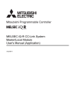
CHAPTER 1
ETHERNET ADAPTER MODULE
The Ethernet adapter module connects external devices on the Ethernet network to CC-Link IE Field Network.
For details on CC-Link IE Field Network, refer to the following.
User's manual for the master/local module used
CC-Link
IE Field Network
Ethernet adapter module
Switching hub
Ethernet
Configuration
tool
16
Barcode
reader
GOT
CHAPTER 1 ETHERNET ADAPTER MODULE
1
(1) Communication using SLMP
(a) Data of the programmable controller device can be read/written
Device data can be read or written from an external device to a module on the network where the Ethernet
adapter module is connected. Data reading and writing is also available to the devices of the Ethernet adapter
module. For details on SLMP, refer to the following.
SLMP Reference Manual
Ethernet adapter module
CC-Link
IE Field Network
Device reading
or
writing
SLMP
Switching hub
(b) The on-demand function enables data to be sent from the programmable controller
(
Page 89, Section 7.2)
Issuing a send request from the CPU module to the Ethernet adapter module allows data to be sent to the
external device.
Events such as link start instruction and read instruction can be notified to an external device.
In addition, data can be simultaneously sent to all the external devices on Ethernet where the Ethernet adapter
module is also connected (broadcast communications).
Master station (station No. 0)
Ethernet adapter module (station No. 1)
CC-Link IE Field Network
(network No. 1)
External device
Ethernet
On-demand data transmission
17
(2) Connection of MC protocol devices
The message format of SLMP is the same as that of the QnA compatible 3E or 4E frame format of the MC
protocol. Therefore, external devices that support the MC protocol can be connected to CC-Link IE Field Network.
(3) Communications using the specified IP address over CC-Link IE Field Network
(IP packet transfer function) (
Page 105, Section 7.3)
With this function, communications using the specified IP address can be performed over CC-Link IE Field
Network. For example, a personal computer can communicate with the FTP server. Two networks of CC-Link IE
Field Network and Ethernet are not required, resulting in reduced wiring cost.
Conventional way
CC-Link IE Field Network
Ethernet
When the IP packet transfer function is used
Two networks were required.
CC-Link IE Field Network
Ethernet communications (IP packet transfer)
Only CC-Link IE Field Network is
required to perform communications.
The IP packet transfer function allows an IP packet to be transferred from an external device to a request destination. An
Ethernet adapter module cannot be used as a request source or a request destination.
18
CHAPTER 1 ETHERNET ADAPTER MODULE
1
(4) Connection to MELSOFT products or GOTs
The Ethernet adapter module can be also connected to MELSOFT products or GOTs.
Switching hub
MELSOFT
product
(5) Cyclic transmission (
GOT
Page 33, Section 3.2.1 (2))
Data can be periodically exchanged with the master station through link devices (RX, RY, RWr, and RWw).
Master station
Ethernet adapter module
CPU
module
Master/local
module
Ethernet
adapter module
X
RX
RX
Y
RY
RY
RWw
RWw
RWr
RWr
W
19
(6) Transient transmission
Transient transmission allows direct access from a master or local station to the devices or buffer memory of the
Ethernet adapter module.
Requests from the master or local station to the Ethernet adapter module are made with dedicated instructions.
(
User's manual for the master/local module used)
Master station
CPU module
Command
Master/local
module
Ethernet
adapter module
REMFR
Device
Buffer memory
1234H
1234H
(7) Parameter setting (
Page 184, Section 10.3)
Parameters can be set in the configuration tool incorporated in the Ethernet adapter module. Therefore, there is
no need to create any configuration programs. The configuration tool will be started from a Web browser.
20
CHAPTER 1 ETHERNET ADAPTER MODULE
1
(8) Diagnostics
(a) CC-Link IE Field Network diagnostics
By connecting GX Works2 to a master/local module, the condition of the entire CC-Link IE Field Network can
be viewed on the CC-Link IE Field Network diagnostics dialog box. (
User's manual for the master/local
module used)
The status of the entire CC-Link IE Field
Network can be monitored.
(b) Ethernet adapter diagnostics
In the Ethernet Adapter Diagnostics dialog box, the condition, such as an error occurred in communication with
an external device, can be checked. (
Page 198, Section 10.7)
21
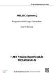
CHAPTER 2
PART NAMES
This chapter describes the Ethernet adapter module parts and their names.
1)
2)
3)
5)
4)
No.
1)
Name
Power supply part
Description
Power is supplied to the Ethernet adapter module through this part. (24VDC)
(
Page 23, Section 2.1)
The Ethernet adapter module is connected to CC-Link IE Field Network at this part.
• The communication status of CC-Link IE Field Network is indicated with the LEDs.
2)
CC-Link IE Field Network part
(
Page 24, Section 2.2 (1))
• The switch on this part is used for controlling the operation of the Ethernet adapter module.
(
Page 26, Section 2.2 (2))
The Ethernet adapter module is connected to the Ethernet at this part.
3)
Ethernet part
The communication status of the Ethernet is indicated with the LEDs. (
2.3)
4)
Serial number display
The serial number on the rating plate is indicated.
5)
DIN rail hook
This hook is used to mount the module to a DIN rail.
22
Page 28, Section
CHAPTER 2 PART NAMES
2.1
Power Supply Part
Respective names of the Ethernet adapter module's power supply part are shown below.
2
1)
2)
3)
4)
No.
Name
POWER LED
1)
Part
Indicates the operating status of the power supply part.
Normally operating.
Off
No power input, power failure, or hardware failure
2)
FG terminal
A ground terminal connected to the shield pattern on the printed circuit board (M3.5 screw)
3)
LG terminal
A terminal grounded to a power filter (M3.5 screw)
4)
Power input
terminal
Terminals for power input. (M3.5 screws)
For the specifications of the power supply to be connected, refer to "Performance specifications of each part."
(
Page 31, Section 3.2.1 (1))
23
2.1 Power Supply Part
On (green)
2.2
CC-Link IE Field Network Part
Respective names of the Ethernet adapter module's CC-Link IE Field Network part are shown below.
(1)
(2)
(3)
(1) LEDs
Name
RUN LED
Description
Indicates the operating status.
On
Normally operating. (RUN status)
Normally operating. (STOP status)
• The Ethernet adapter module's switch is set to STOP. (Data transfer among the Ethernet adapter module
devices is stopped.)
Flashing
• The master station is in the STOP status. (Data transfer among the Ethernet adapter module devices is
continued.)
• A remote STOP request is being received.
• The Ethernet adapter module stopped due to an error (except a watchdog timer error).
Off
A hardware failure or a watchdog timer error has occurred.
On
Online mode
Flashing
Test mode
MODE LED
Indicates the mode.
Off
D LINK LED
On
Data link in operation (cyclic transmission in progress)
Flashing
Data link in operation (cyclic transmission stopped)
Off
Data link not in operation (disconnected) or the module is in offline mode.
On
Data being sent
Off
No data being sent
On
Data being received
Off
No data being received
SD LED
Indicates the data sending status on CC-Link IE Field Network.
RD LED
24
Offline mode
Indicates the data link status of CC-Link IE Field Network.
Indicates the data receiving status on CC-Link IE Field Network.
CHAPTER 2 PART NAMES
Name
Description
Indicates the error status of the Ethernet adapter module.
ERR. LED
The error details can be checked by the CC-Link IE Field Network diagnostics. (
Page 141, Section 9.2.1)
One of the following errors occurred in the Ethernet adapter module.
2
• Multiple modules with the same station number exist on CC-Link IE Field Network.
On
• Network parameters for CC-Link IE Field Network is corrupted. Or, there is an error in the reserved station
setting, the number of connected stations, or the network number setting.
• There is an error in the network parameter settings for the Ethernet adapter module.
Off
Normally operating.
Indicates the error status of the received data and the line. When this LED is on, check the L ER LED for "P1" or
"P2" to see on which port the error was detected.
L ERR. LED
The error details can be checked by the CC-Link IE Field Network diagnostics. (
Page 141, Section 9.2.1)
This LED automatically turns off when the module has received normal data and loopback is completed.
• The Ethernet adapter module has received abnormal data.
On
• The Ethernet adapter module is performing loopback (only the Ethernet adapter module with a serial number
(first five digits) of "12102" or later).
• The Ethernet adapter module has received normal data.
Off
• The Ethernet adapter module does not perform loopback (only the Ethernet adapter module with a serial number
(first five digits) of "12102" or later).
STATION NO.
Indicates the station number of the Ethernet adapter module.
Indicates the station number.
Ex. Station No.15
1
2
On
4
8
10
2.2 CC-Link IE Field Network Part
100
1
10 + 5 = 15
Off
The station number has not been set.
Remark
● LED indication during line test execution
While a line test is being performed from the master station, the following LEDs are flashing.
• MODE LED
• D LINK LED
• ×100 LED
: On
: Flashing
Flashing
For execution of the line test, refer to the following.
User's manual for the master/local module used
25
(2) Switch
With this switch, the operation of the Ethernet adapter module can be controlled.
Name
Description
The Ethernet adapter module can be reset by the following method.
Set the switch with your fingertip. Using a tool such as a screwdriver may damage the switch.
1.
Shift the switch to RESET/TEST for one
second or longer.
Switch
: Flashing
Flashes several times
and then turns off
Hold the switch and do not release it.
2.
Confirm that the ERR. LED flashes
several times and then turns off.
RESET/TEST
3.
Switch
Set the switch back to the STOP
position.
The switch will automatically return to the
STOP position when released.
You can also switch the Ethernet adapter module to the test mode and reset the parameters to default values.
For switching to the test mode, refer to "Testing the Module Before Wiring." (
Page 57, Section 6.3)
For resetting the parameters to default values, refer to "Resetting Parameters to Factory Default Values."
(
Page 222, Appendix 6)
Transfer between the link devices (cyclic data from the master station) and the devices of the Ethernet adapter
module is stopped. (Transfer is stopped while cyclic transmission with the master station is continued.)
This transfer stop can prevent the data exchanged between an external device and the Ethernet adapter module
from being sent to the master and local stations. The STOP switch is used for a purpose, such as debugging
between the Ethernet adapter module and external devices.
Ex. Debugging communication data with an external device using the STOP switch
STOP*1
(1)
Set the switch to "STOP."
(2)
Data transfer between the link devices and devices of the Ethernet adapter module is stopped, and the
Ethernet adapter module is separated from the master station control.
(3)
Check if communications are normally performed between the Ethernet adapter module and an external
device. Because transfer is stopped, data exchanged between the Ethernet adapter module and the external
device will not be sent to the master and local stations.
(4)
After checking the above, write the parameters to the Ethernet adapter module and start the system
operation.
Cyclic transmission starts between the Ethernet adapter module and the master station. (Data communication
RUN
between the Ethernet adapter module and external devices is performed regardless of the switch status.)
*1
26
Even if the switch is set to "STOP", the Ethernet adapter module is shown to be in the cyclic transmission status at the
master station.
CHAPTER 2 PART NAMES
(3) Connectors
Name
Description
The PORT1 connector for connecting to CC-Link IE Field Network. (RJ45 connector)
P1
Connect an Ethernet cable to this. (
2
Page 61, Section 6.4.2)
There are no restrictions on the connection order of the cables for the "P1" and "P2" connectors.
• The Ethernet adapter module has received abnormal data.
On
• The Ethernet adapter module is performing loopback (only the Ethernet adapter module with a serial number
(first five digits) of "12102" or later).
L ER
LED
• The Ethernet adapter module has received normal data.
Off
• The Ethernet adapter module does not perform loopback (only the Ethernet adapter module with a serial number
(first five digits) of "12102" or later).
LINK
On
LED
Off
Linkup in progress
Linkdown in progress
The PORT2 connector for connecting to CC-Link IE Field Network. (RJ45 connector)
P2
Connect an Ethernet cable to this. (
Page 61, Section 6.4.2)
There are no restrictions on the connection order of the cables for the "P1" and "P2" connectors.
L ER LED
LINK LED
(Same as the "P1" connector)
2.2 CC-Link IE Field Network Part
27
2.3
Ethernet Part
This section describes the names of the Ethernet adapter module's Ethernet part.
1)
*1
2)
*1
No.
Do not remove this sticker since it is used for maintenance.
Name
INIT. LED
1)
Indicates the initial processing status.
On
Initial processing completed.
Off
Initial processing not completed.
COM.ERR. LED
On
Off
Ethernet port
2)
LINK/
SPEED
SD/RD
28
Description
On
Indicates the Ethernet communication status.
An error occurred in Ethernet communication.
Normal Ethernet communication
Connector for Ethernet connection. (RJ45 connector)
Connects an Ethernet cable. (
Page 61, Section 6.4.2)
• Green: Linkup in progress at 1Gbps
• Orange: Linkup in progress at 100Mbps
Off
Linkdown in progress
On
Data being sent or received in Ethernet communication
Off
No data transfer in Ethernet communication
CHAPTER 3 SPECIFICATIONS
CHAPTER 3
SPECIFICATIONS
This chapter describes the specifications of the Ethernet adapter module.
3.1
General Specifications
Item
3
Specification
Operating ambient
0 to 55°C
temperature
Storage ambient
-25 to 75°C
temperature
Operating ambient
humidity
5 to 95%RH, non-condensing
Storage ambient
humidity
Constant
Frequency
Compliant with
Vibration resistance
JIS B 3502 and
IEC 61131-2
Under
intermittent
vibration
Under
continuous
vibration
Sweep count
10 times each in
5 to 8.4Hz
3.5mm
8.4 to 150Hz
9.8m/s2
5 to 8.4Hz
1.75mm
8.4 to 150Hz
4.9m/s2
X, Y, and Z
directions
3.1 General Specifications
Operating atmosphere
No corrosive gases
Operating altitude*1
0 to 2000m
Installation location
Inside a control panel
Overvoltage category
*2
II or lower
degree*3
2 or lower
Equipment class
*1
Half amplitude
Compliant with JIS B 3502 and IEC 61131-2 (147m/s2, 3 times each in X, Y, and Z directions)
Shock resistance
Pollution
acceleration
Class I
Do not use or store the Ethernet adapter module under pressure equivalent to the atmospheric pressure of an elevation
of 0m or higher. Doing so may cause malfunction. When applying pressure to the module, please consult your local
Mitsubishi representative.
This indicates the section of the power supply to which the equipment is assumed to be connected between the public
power distribution network and the machinery within premises.
Category II applies to equipment for which electric power is supplied from fixed facilities. The surge voltage withstand
level for up to the rated voltage of 300V is 2500V.
This index indicates the degree to which conductive material is generated in terms of the environment in which the
equipment is used.
At pollution level 2, only non-conductive pollution occurs. A temporary conductivity caused by condensing must be
expected occasionally.
*2
*3
For compliance with the EMC directive, refer to "EMC and Low Voltage Directives" in this manual.
(
Page 224, Appendix 8)
29
3.2
Performance Specifications
The following describes the performance specifications of the Ethernet adapter module.
Item
Specification
X
Y
8192 points, 1KB
(X0 to X1FFF are assigned to RX0 to RX1FFF.)
8192 points, 1KB
(Y0 to Y1FFF are assigned to RY0 to RY1FFF.)
8192 points, 16KB
Number of device points
W
(1024 points of W0 to W3FF are assigned to RWw0 to RWw3FF.
1024 points of W1000 to W13FF are assigned to RWr0 to RWr3FF.)
SB
8192 points, 1KB
SW
8192 points, 16KB
SM
2048 points, 256 bytes
SD
2048 points, 4KB
Number of writes to the parameter memory
Up to 100000 times
Year, month, date, hour, minute, and second (with automatic leap year detection)
When connected to a network, the clock is periodically synchronized with the clock in the
Clock function (for display of data such as the
date and time at which an error occurred)
CPU module on the master station via the network. (Initial value: 2000/1/1 00:00:00)
If the Ethernet adapter module is powered off and then on, the clock will restart at the time
the power was turned off. (The clock does not run while the power is off.)
Therefore, the date and time of an error that occurred during initial processing may be
different from the actual date and time.)
Internal current consumption (24VDC)
External dimensions
Weight
30
0.6A
H
90mm
W
135mm
D
109mm
0.7kg
CHAPTER 3 SPECIFICATIONS
3.2.1
Performance specifications of each part
The performance specifications of each part of the Ethernet adapter module are described below.
Power supply
part
CC-Link IE Field
Network part
Ethernet
part
3
(1) Power supply part
Item
Input voltage
(
Page 32, Section 3.2.1 (1) (a))
Current consumption
Inrush current
Page 32, Section 3.2.1 (1) (b))
Allowable momentary power failure time
(
Page 32, Section 3.2.1 (1) (c))
Withstand voltage
Insulation resistance
24VDC (-35% to +30%)
0.6A
100A, 1ms or less
10ms or less
510V AC/min (Altitude: 0 to 2,000m)
Between inputs/LG and outputs/FG
10M or higher by 500VDC insulation resistance tester
(Between inputs/LG and outputs/FG, inputs and LG, outputs and FG)
• By noise simulator of 500Vp-p noise voltage, 1µs noise width, and 25 to 60 Hz noise
Noise immunity
frequency
• Noise voltage IEC 61000-4-4, 2kV
Operation status indicator
LEDs (Normal: On (green), Error: Off)
Fuse
Built-in (not replaceable)
Terminal screw size
M3.5
Applicable wire size
0.75 to 2 mm2
Applicable solderless terminal
Applicable tightening torque
RAV1.25-3.5, RAV2-3.5, 0.8mm or less in thickness
Two solderless terminals can be connected to one terminal.
0.66 to 0.89N•m
31
3.2 Performance Specifications
3.2.1 Performance specifications of each part
(
Specification
(a) Input voltage
Input voltage is a voltage at which the power supply part operates normally. If it is outside the specified range,
the Ethernet adapter module may detect an error and stop its operation.
(b) Inrush current
Inrush current is a large current that instantaneously flows into a circuit immediately after power is applied.
Reapplying input power after power-off may cause an inrush current that exceeds the specified value. Allow 5
seconds or more before reapplying input power.
Also, select appropriate fuses or breakers for external circuits, considering the possibility of meltdown, sensing
property, and other items shown in this section.
(c) Allowable momentary power failure time
If a momentary power failure occurs, the system detects an input voltage failure and stops its operation.
Allowable momentary power failure time is the period of time that the system can continue its operation after
power is restored.
If a momentary stop exceeding the allowable momentary power failure time occurs, the operation will be
continued by the load of the power supply part, or will be initially started. When the operation is continued, the
operational behavior is the same as that for the momentary stop within the allowable momentary power failure
time.
32
CHAPTER 3 SPECIFICATIONS
(2) CC-Link IE Field Network part
Item
Specification
RWw
8192 points, 16KB
Maximum link points per
RWr
8192 points, 16KB
network
RX
16384 points, 2KB
RY
16384 points, 2KB
RWw
1024 points, 2KB
Maximum link points per
RWr
1024 points, 2KB
station
RX
2048 points, 256 bytes
RY
2048 points, 256 bytes
Station type
Intelligent device station
Station No.
1 to 120
Network No.
1 to 239
Communication method
Token passing method
Communication speed
1Gbps
Transmission path
3
Line or star topology (Coexistence of line topology and star topology is possible.), ring
topology
An Ethernet cable that meets the 1000BASE-T standard:
Connection cable
Category 5e or higher, (Double shielded/STP) Straight cable
(
Maximum station-to-station distance
Page 48, Section 5.2.1)
Up to 100m (compliant with ANSI/TIA/EIA-568-B (Category 5e)) (
Page 65, Section
6.4.4 (7))
Line topology: 12000m (when connecting 1 master station and 120 slave stations)
Star topology: Depends on the system configuration
Number of cascade connections
Up to 20
3.2 Performance Specifications
3.2.1 Performance specifications of each part
Overall cable distance
Ring topology: 12100m (when connecting 1 master station and 120 slave stations)
33
(3) Ethernet part
Item
Specification
For users
32
Number of
For auto-open
1
connections
For MELSOFT
connection
3 (TCP connection: 1*1, UDP connection: 1, Direct connection: 1)
1025 to 4999, 5011 to 65534 (0401H to 1387H, 1393H to FFFEH)
Own Station Port No.
Number of simultaneously connectable
modules
Communication speed
Up to 32
1Gbps or 100Mbps
Communication mode
Full- or Half-duplex
Transmission system
Base band
An Ethernet cable that meets the 1000BASE-T standard:
Category 5e or higher, (Double shielded/STP) Straight cable
For 1Gbps
(
Connection cable
Page 48, Section 5.2.2 (1))
An Ethernet cable that meets the 100BASE-TX standard:
For 100Mbps
*2
Category 5 or higher, (STP) Straight cable
(
Maximum distance between switching hub
and node
Number of cascade connections
Page 48, Section 5.2.2 (1))
Up to 100m
Up to 20
*1
To use two or more TCP connections for a MELSOFT Connection, user connections can be assigned to MELSOFT
*2
Page 191, Section 10.3.3 (1))
Connection. (
Use of double shielded cables is recommended in a high noise environment.
● When connected to a switching hub, the Ethernet adapter module detects and sets 1000BASE-T or 100BASE-TX and
full-or half- duplex communication mode according to the switching hub. When the connected switching hub does not
support the auto-negotiation function, set the switching hub to the half-duplex communication mode.
● The operation of the following connections is not guaranteed. Check the operation at the user's discretion before use.
• Connections using the Internet (public line)
(Internet connection services by Internet service providers or telecommunications carriers)
• Connections using firewall devices
• Connections using broadband routers
34
CHAPTER 3 SPECIFICATIONS
(a) Communication specifications for TCP connection
• Number of resends and resend interval
If the Ethernet adapter module sent a message to an external device and after that did not receive an ACK
from the external device, it will resend the message at the intervals shown below.
Item
Number of resends
Specification
Up to 3 times
Up to 64 seconds (Varies depending on the line status.)
If the resend fails, the amount of time is doubled. (The maximum value is 64
3
seconds.)
Resend interval
Ex. When the interval for the first resend is 20 seconds;
1st: 20s, 2nd: 40s, 3rd: 64s
If the Ethernet adapter module fails to receive an ACK response from the external device even when it
resends data as many times as the number of resends, it regards that there is no external device, causing
disconnection.
When the connection is disconnected, send a connection establishment request from the external device,
reestablish a connection, and resend a request message.
• Alive check by KeepAlive
The Ethernet adapter module performs alive check by KeepAlive.
The Ethernet adapter module sends an alive check message in 5 seconds after receiving the last
message from an external device. If no response is returned from the external device for 5 seconds, the
module resends the alive check message. The module resends the message for 7 times at intervals of 5
seconds.
If no response is received for 45 seconds from the last message reception from the external device, the
connection again.
When the external device does not support the TCP KeepAlive function, the connection may be closed.
• Connection establishment request
When a connection establishment request is sent from an external device to the port of the Ethernet
adapter module, where a connection has been already established, the Ethernet adapter module will not
respond. Therefore, if no response is returned even after a connection establishment request is sent to the
Ethernet adapter module, check if the specified port number is correct.
35
3.2 Performance Specifications
3.2.1 Performance specifications of each part
Ethernet adapter module will close the connection. Allow 45 seconds or longer before opening the same
3.3
List of the Functions
This section lists the functions of the Ethernet adapter module.
(1) Communications with an external device
Function
Description
Refer to
Device data can be read or written from an external device to a
Communications from
module on the network where the Ethernet adapter module is
an external device
connected. Data also can be read or written from/to the Ethernet
Page 66, Section 7.1
adapter module.
Issuing a send request from the CPU module to the Ethernet
Communications
using SLMP
adapter module allows data to be sent to the external device.
Communications from
Events such as link start instruction and read instruction can be
a CPU module
notified to an external device.
(on-demand function)
In addition, data can be simultaneously sent to all the external
Page 89, Section 7.2
devices on Ethernet where the Ethernet adapter module is also
connected (broadcast communications).
With this function, communications using the specified IP address
can be performed over CC-Link IE Field Network. For example, a
Communication using the specified IP
personal computer connected to the Ethernet part can
address over CC-Link IE Field Network
communicate with another personal computer connected to a Built-
(IP packet transfer function)
in Ethernet port QCPU.
Page 105, Section 7.3
Two networks of CC-Link IE Field Network and Ethernet are not
required, resulting in reduced wiring cost.
Connection to MELSOFT products or
The Ethernet adapter module can be also connected to MELSOFT
GOTs
products or GOTs.
(2) CC-Link IE Field Network communications
Function
Cyclic transmission
Description
Data can be periodically exchanged with the master station through
link devices (RX, RY, RWr, and RWw).
Refer to
Page 66, Section 7.1
The devices or buffer memory of the Ethernet adapter module can
Transient transmission
be directly accessed from the master or local station.
Requests from the master or local station to the Ethernet adapter
module are made with dedicated instructions.
(3) Other functions
Function
Device/buffer memory batch monitor
Description
The values in the devices and buffer memory of the Ethernet
adapter module can be monitored.
Refer to
Page 196, Section 10.6
Information such as the latest error that occurred in the Ethernet
Ethernet adapter diagnostics
adapter module and the status of the communications with an
external device can be checked.
36
Page 198, Section 10.7
CHAPTER 3 SPECIFICATIONS
3.4
Buffer Memory List
The buffer memory is used for exchanging data between the Ethernet adapter module and a master/local module or an
external device.
The contents of the buffer memory return to the default state (initial values) when the system is powered off or reset.
Address
(Decimal
Name
(Hexadecimal))
0
(1H)
Module operation area
19
Own station information
(13H)
(PORT1 and PORT2)
20 to 21
(16H to 19H)
29
(1DH)
Own station information
30 to 31
(Ethernet port)
(1EH to 1FH)
(24H)
37
(25H)
38
Own station information
(26H)
(Parameters)
39 to 47
48
(31H to 2FFH)
Read
Own station MAC address
Read
System area
Own station IP address
0
0
Mode
0
Read
Network No.
0
Read
Station No.
0
Read
Ethernet port operation area
(300H)
(area for initial processing)
Page 202,
Appendix 1.2 (1)
Page 202,
Appendix 1.2 (2)
Page 202,
Appendix 1.2 (2)
Page 202,
Appendix 1.2 (3)
0001H
Read
Page 202,
Appendix 1.2 (3)
System area
768
Appendix 1.2 (1)
Function check area*1
(30H)
49 to 767
0
System area
(27H to 2FH)
Page 202,
System area
36
Page 201,
Own station subnet mask
(20H to 21H)
(22H to 23H)
Read
Read
32 to 33
Appendix 1.1 (2)
Initial processing error code
0
Read
Page 203,
Appendix 1.3 (1)
37
3.4 Buffer Memory List
(1AH to 1CH)
34 to 35
System area
26 to 28
Appendix 1.1 (1)
Appendix 1.1 (3)
System area
Own station IP address
(14H to 15H)
Page 201,
Own station MAC address
(10H to 12H)
Refer to
Page 201,
0
System area
16 to 18
22 to 25
Read
Ethernet port LED information
(2H)
(3H to FH)
Station No. LED information
3
Read/Write
Read
2
3 to 15
value
Module LED information
(0H)
1
Initial
Address
(Decimal
Name
(Hexadecimal))
769 to 783
(301H to 30FH)
(310H)
785
(311H)
(312H)
787
(313H)
788
(314H)
(Connection information area
792
(318H)
793
(319H)
794 to 795
(31AH to 31BH)
796 to 799
(31CH to 31FH)
(Connection information area
1297
(511H)
1299
1300
(514H)
Ethernet port operation area
1301
(Auto-open UDP port area)
1305
(519H)
1306 to 1307
(51AH to 51BH)
38
1
Own Station Port No.
0
TCP connection system
0
Read
Connection status
0
System area
Latest error code
0
Read
Destination port No.
0
Read
Destination IP address
0
Read
System area
Page 203,
Appendix 1.3 (2)
Page 203,
Appendix 1.3 (2)
Open system
3
Protocol
1
Page 203,
Appendix 1.3 (2)
Page 204,
Same as Connection information area No.1
Own Station Port No.
(513H)
(518H)
Communication data code
Communication data code
(512H)
1304
0
Appendix 1.3 (3)
Read
1298
(516H to 517H)
Protocol
No.2 to No.32)
(510H)
1302 to 1303
1
Ethernet port operation area
1296
(515H)
Open system
No.1)
(316H to 317H)
(320H to 50FH)
Refer to
Ethernet port operation area
790 to 791
800 to 1295
Read/Write
Read
786
(315H)
value
System area
784
789
Initial
0
Page 204,
Appendix 1.3 (4)
1388H
System area
Connection status
0
Read
System area
Latest error code
0
Destination port No.
0
Destination IP address
0
Read
Page 204,
Appendix 1.3 (4)
Page 204,
Appendix 1.3 (4)
CHAPTER 3 SPECIFICATIONS
Address
(Decimal
Name
(Hexadecimal))
1308 to 1311
(51CH to 51FH)
1312
(520H)
(522H)
1315
Protocol
1
Communication data code
0
Own Station Port No.
(523H)
1316
(524H)
Ethernet port operation area
1317
(MELSOFT application
(525H)
communication port (UDP/IP)
1318 to 1319
area for the system)
(526H to 527H)
1320
(528H)
1321
(529H)
1322 to 1323
(52AH to 52BH)
3
Read
1329
(531H)
1330
(532H)
System area
Connection status
0
Read
System area
Latest error code
0
Destination port No.
0
Destination IP address
0
Read
Open system
0
Protocol
0
Communication data code
0
Own Station Port No.
(533H)
1332
Ethernet port operation area
(534H)
(MELSOFT application
1333
communication port (TCP/IP)
(535H)
area for the system)
1334 to 1335
(536H to 537H)
1336
(538H)
1337
(539H)
1338 to 1339
(53AH to 53BH)
System area
Page 205,
Appendix 1.3 (5)
Page 205,
Appendix 1.3 (5)
Read
1331
Appendix 1.3 (5)
138AH
TCP connection system
0
Connection status
0
System area
Latest error code
0
Destination port No.
0
Destination IP address
0
Read
3.4 Buffer Memory List
(530H)
Page 205,
1389H
System area
1328
(53CH to 53FH)
Refer to
System area
1314
1340 to 1343
Read/Write
(521H)
(52CH to 52FH)
value
System area
1313
1324 to 1327
Initial
Page 206,
Appendix 1.3 (6)
Page 206,
Appendix 1.3 (6)
39
Address
(Decimal
Name
(Hexadecimal))
1344
(540H)
1345
(541H)
1347
(545H)
Ethernet port operation area
port)
(546H to 547H)
1352
(548H)
1353
(549H)
1354 to 1355
(54AH to 54BH)
(54CH to 54FH)
(550H)
1361
(551H)
1363
(555H)
Ethernet port operation area
configuration tool)
(556H to 557H)
1368
(558H)
1369
(559H)
1370 to 1371
(55AH to 55BH)
(55CH to 800H)
40
Connection status
0
Read
System area
Latest error code
0
Destination port No.
0
Destination IP address
0
Read
System area
Page 207,
Appendix 1.3 (7)
Page 207,
Appendix 1.3 (7)
Page 207,
Appendix 1.3 (7)
Open system
3
Protocol
1
0
Page 208,
Appendix 1.3 (8)
1392H
System area
Connection status
0
Read
System area
Latest error code
0
Destination port No.
0
Destination IP address
0
(Connection port for the
1366 to 1367
1372 to 2048
Own Station Port No.
(553H)
Refer to
1390H
System area
Communication data code
(552H)
1365
0
Read
1362
(554H)
1
System area
1360
1364
Protocol
Read/Write
(Direct MELSOFT connection
1350 to 1351
1356 to 1359
3
Own Station Port No.
(543H)
1349
Open system
Communication data code
(542H)
(544H)
value
Read
1346
1348
Initial
Read
Page 208,
Appendix 1.3 (8)
Page 208,
Appendix 1.3 (8)
CHAPTER 3 SPECIFICATIONS
Address
(Decimal
Name
(Hexadecimal))
2049
(801H)
2050
Error count
(803H to 80FH)
2065
(811H)
2066
(812H)
(813H)
2068
(814H)
2069
Ethernet port error log area
(815H)
(Error log No.1)
2070 to 2071
(816H to 817H)
2072 to 2075
(818H to 81BH)
2077
(81DH)
2078 to 2079
(81EH to 81FH)
2080 to 3087
Ethernet port error log area
(820H to C0FH)
(Error log No.2 to No.64)
(D00H)
3329 to 5375
(D01H to 14FFH)
Ethernet port connection status
(1500H to 1501H)
data area
5378 to 5631
(1502H to 15FFH)
Error code
0
Connection No.
0
Open system
0
Protocol
0
Own Station Port No.
0
Destination port No.
0
Destination IP address
0
Date and time
0
Command code
0
Subcommand code
0
System area
System area
Page 209,
Appendix 1.4 (3)
Page 209,
Appendix 1.4 (3)
Page 210,
Same as error log No.1
Appendix 1.4 (4)
Communication status
0
Read
Page 210,
Appendix 1.5 (1)
System area
5376 to 5377
3
System area
Ethernet port line status
Page 209,
Open completion signal
0
Read
Page 211,
Appendix 1.6 (1)
41
3.4 Buffer Memory List
(81CH)
Appendix 1.4 (1)
Appendix 1.4 (2)
Read
2076
3328
0
Read
2067
Refer to
Page 209,
0
System area
(810H)
(C10H to CFFH)
Read/Write
Read
Error log write pointer
2064
3088 to 3327
value
Ethernet port error log area
(802H)
2051 to 2063
Initial
Address
(Decimal
Name
(Hexadecimal))
5632
(1600H)
5633
(1601H)
5634
On-demand function data
(1602H)
value
Read/Write
Send request flag
0
Read/Write
Send completed flag
0
Read
Completion code
0
Read
Control data
0
Read/Write
Send data
0
Read/Write
System area
sending area
5635 to 5643
(1603H to 160BH)
(channel 1)*1
5644 to 6603
(160CH to 19CBH)
6604 to 6655
(19CCH to 19FFH)
On-demand function data
6656 to 9727
(1A00H to 25FFH)
9728 to 29697
(2600H to 7401H)
*1
sending area
Page 92,
Section 7.2.5 (1)
Page 92,
Section 7.2.5 (2)
Page 92,
Section 7.2.5 (3)
Page 93,
Section 7.2.5 (4)
Section 7.2.5
(channels 2 to 4)*1
System area
Check the corresponding serial No. and software version. (
Refer to
Page 92,
Same as channel 1
Do not write data to "System area".
Doing so may cause the Ethernet adapter module to malfunction.
42
Initial
Page 233, Appendix 10)
CHAPTER 3 SPECIFICATIONS
3.5
SLMP
The Ethernet adapter module's devices can be read or written with command messages in the predefined format from
an external device. For details on SLMP, refer to the following.
SLMP Reference Manual
3.5.1
3
Available command list
The following table lists the commands that can be executed from an external device to the Ethernet adapter module.
The part in the Subcommand column varies depending on the specified device. (
Item
Type
Operation
Command
Subcommand
001
Read
0401
000
Write
Read Random
1401
0403
Reads values in 1-point units from bit devices (consecutive device
numbers).
• Reads values in 16-point units from bit devices (consecutive device
numbers).
• Reads values in 1-word units from word devices (consecutive device
numbers).
Writes values to bit devices (consecutive device numbers) in 1-point units.
000
• Writes values to bit devices (consecutive device numbers) in 16-point
units.
• Writes values to word devices (consecutive device numbers) in 1-word
units.
001
Writes values in 1-point units to bit devices by specifying the device
numbers. Discrete device numbers can be used.
1402
• Specifies a device number in 16- or 32-point units to write a value to a bit
device. Discrete device numbers can be used for specification.
• Specifies a device number in word units to write a value to a word
device. Discrete device numbers can be used for specification.
Entry Monitor Device
0801
000
Registers a device to be read by Execute Monitor (command: 0802).
Execute Monitor
0802
0000
Reads the value of the device registered by Entry Monitor Device
(command: 0801).
Read Block
0406
000
Specifies n points (1 point: 16 bits) of word or bit devices as one block, and
reads multiple blocks of data. Discrete device numbers can be used for
specification.
Write Block
1406
000
Specifies n points (1 point: 16 bits) of word or bit devices as one block, and
writes multiple blocks of data. Discrete device numbers can be used.
Discrete device numbers can be used for specification.
Read
0613
0000
Reads buffer memory data of the Ethernet adapter module.
Write
1613
0000
Writes data to the buffer memory of the Ethernet adapter module.
Remote Run
1001
0000
Executes remote RUN to the Ethernet adapter module.
Remote Stop
1002
0000
Executes remote STOP to the Ethernet adapter module.
Remote Reset
1006
0000
Executes remote RESET to the Ethernet adapter module.
Read Type Name
0101
0000
Reads the model name and code of the Ethernet adapter module.
Clear Error
1617
0000
Turns off the COM.ERR. LED on the Ethernet adapter module.
Ondemand
2101
0000
Issues a send request from the CPU module to the Ethernet adapter
module and sends data to the external device.
Remote
Control
43
3.5 SLMP
3.5.1 Available command list
000
Specifies a device number to read the device value. Discrete device
numbers can be used.
• Reads bit devices in 16- or 32-point units.
• Reads word devices in 1- or 2-word units.
000
Memory
Description
001
Device
Write Random
SLMP Reference Manual)
3.5.2
Ranges of accessible devices and buffer memory
Within the following device and buffer memory ranges, external devices can access the Ethernet adapter module.
(1) Devices
Device
Input
Output
Device No. range
X
0000 to 1FFF
Unit
Hexadecimal
Y
0000 to 1FFF
Hexadecimal
Link special relay
SB
0000 to 1FFF
Hexadecimal
Link special register
SW
0000 to 1FFF
Hexadecimal
Special relay
SM
0000 to 2047
Decimal
Special register
SD
0000 to 2047
Decimal
Link register
W
0000 to 1FFF
Hexadecimal
(2) Buffer memory
For the access ranges and read and write availabilities, refer to "Buffer Memory List". (
3.4)
44
Page 37, Section
CHAPTER 4 PROCEDURE BEFORE THE OPERATION
CHAPTER 4
PROCEDURE BEFORE THE
OPERATION
This chapter describes the procedure to be taken before operating the Ethernet adapter module.
4.1
Start-Up Procedure
4
The following shows how to start up the system where the Ethernet adapter module is used.
Check box
Setting on the master station
Set network parameters on the master station.
User's manual for the master/local
module used
Installation
Page 52, Section 6.1,
Mount the module to the DIN rail, and wire the power supply part.
Page 52, Section 6.2,
Page 59, Section 6.4.1
4.1 Start-Up Procedure
Unit test
Page 57, Section 6.3
Check the Ethernet adapter module for hardware failure.
Ethernet cable connection
Page 61, Section 6.4.2
Connect Ethernet cables to the Ethernet adapter module.
Parameter setting
Set parameters for connection to CC-Link IE Field Network and
Ethernet.
Page 175, Section 10.1,
Page 184, Section 10.3,
Page 195, Section 10.5
To the next page
45
Check box
Data link start
Page 26, Section 2.2 (2)
Shift the switch on the Ethernet adapter module to RUN.
CC-Link IE Field Network diagnostics
Check whether communication can be normally performed using the
CC-Link IE Field Network diagnostics on the master station.
Communication with an external device
User's manual for the master/
local module used
Page 141, Section 9.2.1
Page 79, Section 7.1.5 (2)
Send SLMP using an external device.*1 *2
Ethernet diagnostics
Page 198, Section 10.7
Check whether communication can be normally performed using the
Ethernet adapter diagnostics.
*1
Using the on-demand function enables data to be sent from the Ethernet adapter module to an external device.
*2
IP communications can be performed between external devices over CC-Link IE Field Network. (
Section 7.3)
(
46
Page 89, Section 7.2)
Page 105,
CHAPTER 5 SYSTEM CONFIGURATION
CHAPTER 5
SYSTEM CONFIGURATION
This chapter describes a configuration of the system containing the Ethernet adapter module.
For the overall CC-Link IE Field Network configuration, refer to the following.
User's manual for the master/local module used
5.1
Network Configuration
The following shows a network configuration for the Ethernet adapter module.
Through a switching hub, the Ethernet adapter module can communicate with up to 32 external devices at the same
time. Direct connection is also available between the Ethernet adapter module and an external device.
Master
station
5
Ethernet adapter module
CC-Link
IE Field Network
Switching hub
5.1 Network Configuration
Ethernet
Configuration tool
Barcode reader
GOT
Up to 32 devices
External devices must be on the same network as the Ethernet adapter module; therefore, those on different networks
cannot be connected using devices such as a router.
47
5.2
Network Components
The following shows network components.
5.2.1
CC-Link IE Field Network
For network components of CC-Link IE Field Network, refer to the following.
User's manual for the master/local module used
5.2.2
Ethernet
(1) Cables
Use the 1000BASE-T or 100BASE-TX compliant Ethernet cables.
Communication
Ethernet cable
speed
1Gbps
100Mbps
Category 5e or higher,
(STP) Straight cable
Category 5 or higher,
(STP) Straight cable
Connector
Standard
Cables that meet the following standards:
RJ45 connector
• IEEE802.3(1000BASE-T)
• ANSI/TIA/EIA-568-B(Category 5e)
Cables that meet the following standards:
RJ45 connector
• IEEE802.3(1000BASE-T/100BASE-TX)
• ANSI/TIA/EIA-568-B(Category 5)
(a) Recommended products
Ethernet cables meeting the 1000BASE-T or 100BASE-TX standard are available from Mitsubishi Electric
System & Service Co., Ltd. (Cable catalogs are also available.)
Connectors can be customized to the specified length. Please consult your local Mitsubishi service
representative.
Type
Ethernet cable
Model (manufacturer)
SC-E5EW series
(Mitsubishi Electric System & Service Co., Ltd.)
Remark
● Cable types
The following types are available depending on the operating environment.
• Standard type: Cables used in control panels or indoors
• L type: Cables for outdoor connections
Special cables, such as flame-retardant or water-tight cables, and relay adapters are also available. Please consult your
local Mitsubishi Electric System & Service Co., Ltd.
● For order or inquiry on the cables: Mitsubishi Electric System & Service Co., Ltd.
http://www.melsc.co.jp/business/
48
CHAPTER 5 SYSTEM CONFIGURATION
(2) Hubs
Use hubs that meet the following conditions 1 to 4. If these conditions are not satisfied, the operation of the hub is
not guaranteed.
• Compliant with the IEEE802.3(1000BASE-T/100BASE-TX) standard
• Supporting the auto MDI/MDI-X function
• Supporting the auto-negotiation function
• Switching hub (layer 2 switch)*1
*1
Repeater hubs cannot be used.
(a) Mitsubishi Electric products
Type
Industrial switching hub
Model
Data communication rate
NZ2EHG-T8
1000Mbps/100Mbps/10Mbps
NZ2EHF-T8
100Mbps/10Mbps
5
5.2 Network Components
5.2.2 Ethernet
49
5.3
Applicable Systems
5.3.1
Configuration tool
(1) Operating environment
The following table lists the operating environment of the personal computer where the configuration tool is used.
(a) Computer requirements
Item
Computer
Description
Personal computer running any of the following operating systems
CPU
Memory
Specifications recommended for the following operating systems
Web browser
Versions recommended for the following operating systems
Hard disk space
512MB or more
Display
Resolution: 1024 × 768 dots or more
Microsoft® Windows®XP Professional Operating System (English version) SP2 or later*1
Microsoft® Windows®XP Home Edition Operating System (English version) SP2 or later*1
Microsoft® Windows Vista® Home Basic Operating System (English version)*1, *2
Microsoft® Windows Vista® Home Premium Operating System (English version)*1, *2
Microsoft® Windows Vista® Business Operating System (English version)*1, *2
Operating system
Microsoft® Windows Vista® Ultimate Operating System (English version)*1, *2
Microsoft® Windows Vista® Enterprise Operating System (English version)*1, *2
Microsoft® Windows® 7 Home Premium Operating System (English version)*1, *2
Microsoft® Windows®7 Professional Operating System (English version)*1, *2
Microsoft® Windows®7 Enterprise Operating System (English version)*1, *2
Microsoft® Windows®7 Ultimate Operating System (English version)*1, *2
Microsoft® Windows®7 Starter Operating System (English version)*1, *2
Interface
*1
*2
Ethernet port
Installation of .NET Framework 2.0 SP2 or later is required.
The .NET Framework 2.0 SP2 or later might have been installed with other software. In this case, the reinstallation of
this package is not required.
Not available for logon users whom Parental Controls are set up.
(b) Precautions on the operating systems
• The 64-bit Windows® XP Professional, Windows Vista®, and Windows®7 cannot be used.
• When the logon user right is Guest, the operating systems cannot be used.
• When Windows® Firewall settings are enabled, direct connection may not function properly.
Disable Windows® Firewall settings.
• The following functions are not available. If any of these is used, this product may not function properly.
• Application start in Windows® Compatibility Mode
• Fast User Switching
• Remote Desktop
• Big Fonts (in the Advanced Setting of Screen Properties)
• Hibernate and Standby of Windows®
50
CHAPTER 5 SYSTEM CONFIGURATION
5.3.2
Software package
GX Works2 allows the status check of the Ethernet adapter module and access to other stations.
GX Developer cannot be used.
Software
Version
GX Works2
Version 1.40S
(1) Precaution
If a GX Works2 version earlier than the above is used, the dialog box will not be displayed correctly.
5
5.3 Applicable Systems
5.3.2 Software package
51
CHAPTER 6
INSTALLATION AND WIRING
This chapter explains installation of the Ethernet adapter module and the wiring method.
6.1
Installation Environment
Install the Ethernet adapter module in an environment that meets the general specifications. (
Page 29, Section
3.1)
Do not install the Ethernet adapter module in the place where:
• The ambient temperature is outside the range of 0°C to 55°C.
• The ambient humidity is outside the range of 5%RH to 95%RH.
• Condensation occurs due to a rapid temperature change.
• Corrosive or combustible gas is present.
• There is conductive powder such as dust and iron powder, oil mist, salinity, or organic solvent.
• The module is exposed to direct sunlight.
• A strong electric or magnetic field is generated.
• The module is directly subject to vibrations or shocks.
6.2
Installation
When installing the Ethernet adapter module to a control panel or any other place, consider the operability,
maintainability, and environmental resistance.
6.2.1
Installation precautions
(1) Do not directly touch any conductive parts and electronic components of the
Ethernet adapter module. Doing so can cause malfunction or failure of the
Ethernet adapter module.
(2) Do not drop or apply strong shock to the Ethernet adapter module.
(3) Do not remove the printed-circuit board of the Ethernet adapter module from
the case. Doing so may cause failure.
(4) Do not release the levers located at the top and bottom of the Ethernet adapter
module. Doing so may cause malfunction or failure of the Ethernet adapter
module.
52
CHAPTER 6 INSTALLATION AND WIRING
6.2.2
Mounting the module to a control panel
To ensure good ventilation and to make replacement of the Ethernet adapter module easy, provide a distance between
the top or bottom of the module and other structures or parts as shown below.
30mm
or more
Control
panel
Door
30mm
or more
50mm or more
50mm or more
6
80mm or more
6.2 Installation
6.2.2 Mounting the module to a control panel
53
6.2.3
Mounting the modules on a DIN rail
The Ethernet adapter module must be mounted on a DIN rail.
The procedure for mounting the Ethernet adapter module on a DIN rail is shown below.
(1) Mounting procedure
1.
Pull down all of the DIN rail hooks on the back of the
Ethernet adapter module.
Pull it until a click sound is heard.
2.
Hang the upper tabs of the Ethernet adapter module
on the DIN rail, and push the module in position.
3.
Lock the DIN rail hooks of the Ethernet adapter
module to secure it in position.
Push each hook until a click sound is heard.
If you cannot reach the hooks, use a tool such as a
screwdriver.
4.
54
Loosen the screw on the DIN rail stopper.
CHAPTER 6 INSTALLATION AND WIRING
5.
Hitch the bottom hook of the DIN rail stopper to the
bottom of the DIN rail.
Hitch the hook according to the orientation of the arrow
on the front of the stopper.
Hitch the hook to
bottom of the DIN rail
6.
Hitch the upper hook of the DIN rail stopper to the
top of the DIN rail.
Hitch the hook to
top of the DIN rail
6
7.
Slide the DIN rail stopper to the left end of the
Ethernet adapter module.
DIN rail
stopper
6.2 Installation
6.2.3 Mounting the modules on a DIN rail
8.
Tighten the screw of the DIN rail stopper with a
screwdriver.
DIN rail
stopper
9.
DIN rail
stopper
Attach another DIN rail stopper on the right side of
the Ethernet adapter module by the same procedure
as the left side.
55
(2) Removal procedure
The Ethernet adapter module can be removed from the DIN rail in reverse order of the mounting procedure.
(3) Applicable DIN rail models (IEC 60715)
• TH35-7.5Fe
• TH35-7.5Al
• TH35-15Fe
(4) DIN rail stopper
Use stoppers that can be attached to the DIN rail.
(5) Interval between DIN rail mounting screws
To ensure the strength of the DIN rail, tighten DIN rail mounting screws (sold separately) 30mm away from the
both edges of the DIN rail and at intervals of 200mm or less.
DIN rail mounting screw
(obtained by user)
DIN rail
35mm
30mm
or less
P
P=200mm or less
56
P
P
30mm
or less
CHAPTER 6 INSTALLATION AND WIRING
6.3
Testing the Module Before Wiring
(1) Unit test
Perform a unit test to check the Ethernet adapter module for hardware failure.
1.
2.
Turn off the power.
Connect PORT1 and PORT2 of the Ethernet
adapter module with an Ethernet cable.
6
Ethernet cable
3.
4.
Turn on the power.
With the switch on the Ethernet adapter
module, repeat 3 cycles of STOP RESET/
Repeat at intervals of less than 1s.
TEST STOP, taking less than 1 second per
cycle. (The MODE LED flashes after the third
Switch
cycle.)
5.
1s or longer
Hold the switch on the Ethernet adapter module
in the RESET/TEST position for 1 second or
Switch
more.
57
6.3 Testing the Module Before Wiring
: Flashing
6.
The unit test starts.
: On
The MODE LED starts flashing, and the ×1 and ×10
: Flashing
LEDs repeat turning and off in the sequence of
12481... and so on.
7.
When the unit test is completed, flashing of the
×1 and ×10 LEDs is stopped, and the D LINK
When completed
: On
: Flashing
LED turns on.
• When completed
The D LINK LED turns on with the ERR. LED off.
• When failed
The following LEDs turn on.
• Either of the ×1 and ×10 LEDs
• ERR. LED
• D LINK LED
If the unit test fails, replace the Ethernet cable and
perform the test again. If it fails again, the Ethernet
adapter module may have hardware failure. Please
When failed
: On
: Flashing
58
consult your local Mitsubishi representative, with a
detailed explanation of the problem.
CHAPTER 6 INSTALLATION AND WIRING
6.4
6.4.1
Wiring
Wiring of the power supply part
(1) Wiring method
The following figure shows an example of wiring to the power supply part.
AC
DC
24V DC
AC
NZ2GF-ETB
FG
LG
INPUT
+24V
24G
6
Ground wire
Grounding
(2) Precautions
Take the following precautions when wiring the power supply.
• Considering the rated current and inrush current of the power supply part, connect a circuit breaker having
an appropriate sensing property or an external fuse causing proper blowout. (A 10A circuit breaker or
• To minimize a voltage drop, use thickest possible power cables (up to 2mm2), and connect them in the
shortest distance by finely twisting them.
• Do not install the power cables together with the main circuit lines (high voltage and large current) and
Ethernet cables. Keep a distance of 100mm or more between them.
• After wiring, always attach the included terminal cover to the power supply part, and do not touch any
terminal while the power is on or the module is operating.
• Use a Class 2 power supply for the external power supply which inputs power to the power supply part.
• Use solderless terminals when wiring the terminal block of the power supply part. To prevent short-circuit
that may occur when a screw become loose, use a solderless terminal with insulation sleeve, of which
thickness is 0.8mm or less. Up to two solderless terminals can be connected to one terminal block.
Solderless terminal with
insulation sleeve
Terminal block
• Use UL-approved solderless terminals and, for processing, use a tool recommended by their manufacturer.
• Tighten the terminal screws on the power supply part within the applicable torque range of 0.66 to 0.89N•m.
• Use the following wires for connection to the power supply part.
Applicable wire size
2
0.75 to 2mm (18 to 14AWG) (stranded wire)
Material
Copper
Temperature rating
75°C or higher
59
6.4 Wiring
6.4.1 Wiring of the power supply part
external fuse is recommended.)
• An input of a signal of a different voltage level may cause malfunction or equipment failure.
• When supplying power to the power supply part, select a power supply having sufficient power capacity.
(Double power capacity or more is recommended.)
For compliance with the EMC directive, refer to "EMC and Low Voltage Directives" in this manual.
(
60
Page 224, Appendix 8)
CHAPTER 6 INSTALLATION AND WIRING
6.4.2
Ethernet cable wiring
The following figure shows the respective ports connected to CC-Link IE Field Network and Ethernet.
6
Connected to CC-Link
IE Field Network
Connected to Ethernet
6.4 Wiring
6.4.2 Ethernet cable wiring
61
(1) Connecting the Ethernet cable
For Ethernet cables, refer to "Network Components". (
Page 48, Section 5.2.2 (1))
(a) Connection
1.
2.
Turn off the power.
Insert the Ethernet cable connector into the port
until a click sound is heard. Pay attention to the
orientation of the connector.
3.
4.
5.
Port for CC-Link IE Field Network
connection
Port for Ethernet
connection
Turn on the power.
Power on the external device connected to the port.
Check if the LED for the port of the connected
Ethernet cable is on.
The time between the power-on and the LINK/SPEED
LED turning on may vary. The LINK/SPEED LED
usually turns on in a few seconds. Note, however, that
the time may be extended further if the linkup process is
repeated depending on the status of the device on the
line.
On
On
If the LINK/SPEED LED does not turn on, refer to the
troubleshooting section and take corrective actions.
(
62
Page 139, CHAPTER 9)
CHAPTER 6 INSTALLATION AND WIRING
(b) Disconnection
1.
2.
Turn off the power.
Pull out the Ethernet cable while pinching the
retaining clip on the connector.
6
There is no need to distinguish between PORT1 and PORT2.
• When using only one port in a star topology, either of PORT1 or PORT2 can be used.
Either port can be used.
6.4 Wiring
6.4.2 Ethernet cable wiring
• When using the two ports in a line topology and a ring topology, there is no restriction on the order in which
PORT1 and PORT2 are connected. For example, PORT1 can be connected to PORT1 or PORT2.
Connection between
PORT1s or PORT2s
Connection between
PORT1 and PORT2
63
6.4.3
Grounding
Observe the following:
• Provide independent grounding when possible. Ground the FG and LG terminals to the protective ground
conductor. (Grounding resistance: 100 or less)
• If independent grounding is not possible, employ shared grounding, making all of the ground wires to the
same length.
Ethernet
adapter module
Another
device
Grounding
(1) Independent grounding
Ethernet
adapter module
Another
device
Ethernet
adapter module
Another
device
Grounding
Best
(2) Shared grounding
Good
(3) Common grounding
Not allowed
• Use the thickest possible ground wires (up to 2mm2). Also, bring the grounding point close to the Ethernet
adapter module as much as possible so that the ground wire can be shortened.
64
CHAPTER 6 INSTALLATION AND WIRING
6.4.4
Precautions
This section provides precautions for wiring to CC-Link IE Field Network and Ethernet.
(1) Ethernet cables
Use Ethernet cables that satisfy the 1000BASE-T or 100BASE-TX standard. (
Page 48, Section 5.2.2 (1))
(2) Laying Ethernet cables
• Place the Ethernet cables in a duct or clamp them. If not, dangling cable may swing or inadvertently be
pulled, resulting in damage to the Ethernet adapter module or cables or malfunction due to poor contact.
• Do not touch the core of the cable connector or the port, and protect it from dirt and dust. If oil from your
hand, dirt, or dust sticks to the core, it can increase transmission loss, causing data link to fail.
• Check the Ethernet cables for:
• Disconnection
• Short circuit
6
• Any connector connection problem
(3) Connecting or disconnecting the Ethernet cable
When connecting or disconnecting the Ethernet cable, hold the connector part of the cable. Failure to do so may
result in damage to the Ethernet adapter module or the cable or malfunction due to poor contact.
(4) Bend radius of the Ethernet cable
There are restrictions on the bend radius of the Ethernet cable. Check the specifications of the Ethernet cable
6.4 Wiring
6.4.4 Precautions
used.
(5) If the retaining clip of the Ethernet cable is broken
Do not use any Ethernet cable that has a broken retaining clip. Doing so may cause cable disconnection or
malfunction.
(6) Unused Ethernet ports
To prevent dust from entering the module, attach the provided connector cover.
(7) Maximum station-to-station distance (maximum Ethernet cable length)
The maximum station-to-station distance is 100m. However, it may be shorter depending on the environment. For
details, contact the manufacturer of the cables used.
65
CHAPTER 7
COMMUNICATION OF THE
ETHERNET ADAPTER MODULE
7.1
SLMP Communication and Cyclic Transmission
Communication examples of SLMP communication and cyclic transmission are given below.
7.1.1
System configuration
The following system configuration is used as an example.
Ethernet adapter module (NZ2GF-ETB)
Power supply module (Q62P)
IP address: 192.168.3.30
Subnet mask: 255.255.255.0
Port No.: 2000H
CPU module (Q10UDHCPU)
Master/local module (QJ71GF11-T2)
Master station (station No.0)
X/Y00
to
X/Y1F
Intelligent device station (station No.1)
Network No.1
Switching hub
GX Works2
Configuration tool
External device
R
R
Operating system: Microsoft Windows XP Professional
Web browser: Internet Explorer 8
66
CHAPTER 7 COMMUNICATION OF THE ETHERNET ADAPTER MODULE
7.1.2
Communication details
The following SLMP message is sent from the external device to the Ethernet adapter module.
• By Read (command: 0401), 32-bit data in RY0000 to RY001F (Y0000 to Y001F) are read out.
• By Write (command: 1401), 2-word data (1234H and 5678H) are written to RWr0000 to RWr0001 (W1000 to
W1001).
Through cyclic transmissions, data in link devices of the Ethernet adapter module are periodically exchanged with the
CPU module's devices.
SLMP
RY
0000
Master station
XXXXH
Data reading
Cyclic
transmission
CPU module
Master/local module
X
RX
RX
Y
RY
RY
RWw
RWw
RWr
RWr
W
Ethernet adapter
module
001F
XXXXH
RWr
0000
1234H
0001
5678H
7
Data writing
Ethernet adapter
module
SLMP
Configuration tool
7.1 SLMP Communication and Cyclic Transmission
7.1.2 Communication details
Master station
External device
(1) Communication settings
Item
Setting
Protocol
TCP/IP
TCP connection type
Unpassive
Communication data
code
Binary code
(2) SLMP commands
Item
Type
Command
Subcommand
Read
0401
0000
Write
1401
0000
Operation
Device
Description
Reads values from bit devices (of consecutive device
numbers) in units of 16 points.
Writes values to word devices (of consecutive device
numbers) in units of one point.
67
(3) Link device assignment
(a) Assignment of RX and RY
Master station
CPU module
Master/local
module
X
Ethernet adapter module
RX
RX
X
0000
0000
0000
0000
1000
03FF
03FF
03FF
13FF
(Unused)
(Unused)
1FFF
Y
0000
0000
1000
03FF
RY
1FFF
RY
0000
0000
03FF
03FF
13FF
(Unused)
SLMP
Y
Reading
data of 32 bits
(Unused)
1FFF
External device
1FFF
(b) Assignment of RWr and RWw
Master station
CPU module
W
0000
Ethernet adapter module
Master/local
module
RWr
RWr
W
0000
0000
1000
1000
SLMP
03FF
03FF
13FF
(Unused)
1FFF
13FF
W
RWw
RWw
Writing
data of 2 words
W
1400
0000
0000
0000H
17FF
03FF
03FF
03FF
External device
(Unused)
0FFF
68
CHAPTER 7 COMMUNICATION OF THE ETHERNET ADAPTER MODULE
7.1.3
Network setting on the configuration computer
1.
Open the "Internet Protocol (TCP/IP) Properties" dialog box on the personal computer, and
configure the settings as shown below.
Control Panel
Connection"
"Network and Internet Connections"
"General"
button
"Network Connections"
"Local Area
"Internet Protocol (TCP/IP)"
button
7
2.
Open the "Local Area Network (LAN) Settings" dialog box from the Web browser, and configure
the settings as shown below. If the same network settings are applied to the Ethernet adapter
module and the proxy server, the following settings are not necessary.
[Tools]
[Internet Options]
"Connections"
7.1 SLMP Communication and Cyclic Transmission
7.1.3 Network setting on the configuration computer
Web browser
button
Clear the checkboxes.
69
3.
Open the "Internet Options" dialog box from the Web browser, and select "Local Intranet Zone" as
shown below
Web browser
[Tools]
[Internet Options]
"Security"
Select "Local intranet".
4.
After that, click the
button and configure the settings as shown below.
Select "Enable" or "Prompt".
When "Prompt" is selected, the following dialog box may be displayed during the start-up of the
configuration tool. If this occurs, click the
70
button.
CHAPTER 7 COMMUNICATION OF THE ETHERNET ADAPTER MODULE
7.1.4
Connection to CC-Link IE Field Network
(1) Setting in the master station
Use GX Works2 to set the parameters in the master station. Use the default settings for the parameters other than
those set below.
1.
Create a project on GX Works2.
Select "QCPU (Q mode)" for "PLC Series", and "Q10UDH" for "PLC Type".
[Project]
[New...]
7
2.
Open the "Network Parameter" setting window to set the parameters as follows.
Project window
[Parameter]
[Network Parameter]
[Ethernet/CC IE/MELSECNET]
7.1 SLMP Communication and Cyclic Transmission
7.1.4 Connection to CC-Link IE Field Network
Setting
71
3.
Click the
4.
After the setting, click the
5.
Click the
button to set the parameters as follows.
button.
button to open the refresh parameter setting window. Set the
parameters as follows.
6.
After the setting, click the
7.
In the network parameter setting window, click the
8.
Write the set parameters to the CPU module on the master station.
[Online]
9.
button.
[Write to PLC]
Reset the CPU module or power off and on the system.
RESET
72
button.
or Power OFF
ON
CHAPTER 7 COMMUNICATION OF THE ETHERNET ADAPTER MODULE
(2) Setting in the Ethernet adapter module
Set the parameters to connect the Ethernet adapter module to CC-Link IE Field Network using the configuration
tool.
1.
Start up the configuration tool using a Web browser. (
2.
Open the "Parameter Setting" dialog box in the configuration tool to set the parameters as follows.
Setting item tree
NZ2GF-ETB
[Parameter]
Page 179, Section 10.1.2)
"CC-Link IE Field Network"
7
Click the
4.
Set the IP address of the connected Ethernet adapter module. Open the "Destination Setting"
7.1 SLMP Communication and Cyclic Transmission
7.1.4 Connection to CC-Link IE Field Network
3.
button.
dialog box in the configuration tool to enter the address as follows.
[Online]
[Destination Setting]
73
5.
Write the set parameters to the Ethernet adapter module. (Set the switch on the Ethernet adapter
module to STOP.)
[Online]
[Write]
Click
6.
The following dialog box appears.
Click
7.
74
Set the switch on the Ethernet adapter module to RUN.
CHAPTER 7 COMMUNICATION OF THE ETHERNET ADAPTER MODULE
(3) Checking the connection
After setting the parameters for the master station and the Ethernet adapter module, check if data link can be
normally performed between them, by using the CC-Link IE Field Network diagnostics of GX Works2 connected
to the master station.
1.
From the menu of GX Works2, activate the CC-Link IE Field Network diagnostics.
[Diagnostics]
[CC IE Field Diagnostics]
The following shows the normal condition.
7
,
, and
, is displayed in "Network Status", an error has occurred. Identify
the cause of the error and take corrective action. (
User's manual for the master/local module used)
Ex. If an error occurred in the Ethernet adapter module, the dialog box appears as follows.
75
7.1 SLMP Communication and Cyclic Transmission
7.1.4 Connection to CC-Link IE Field Network
If a mark, such as
7.1.5
Connection to the Ethernet
(1) Configuring the Ethernet adapter module
Configure the parameters for communication between the Ethernet adapter module and external devices, using
the configuration tool.
1.
Start up the configuration tool using a Web browser. (
2.
Open the "Parameter Setting" dialog box in the configuration tool to set the parameters as follows.
Setting item tree
3.
Click the
up as shown below.
Setting
76
NZ2GF-ETB
[Parameter]
Page 179, Section 10.1.2)
"Ethernet"
button to display the "Ethernet Port Connection Setting" window. Set it
CHAPTER 7 COMMUNICATION OF THE ETHERNET ADAPTER MODULE
4.
Click the
button to display the "Detail Setting" dialog box. Set the parameters as
follows.
5.
Click the
6.
In the "Ethernet Port Connection Setting" window, click the
7.
In the "Parameter Setting" dialog box, click the
8.
Set the IP address of the connected Ethernet adapter module. In the "Destination Setting" dialog
button.
7
button.
button.
[Online]
7.1 SLMP Communication and Cyclic Transmission
7.1.5 Connection to the Ethernet
box of the configuration tool, enter a value as shown below.
[Destination Setting]
77
9.
Write the configured parameters to the Ethernet adapter module. (Set the switch on the Ethernet
adapter module to STOP.)
[Online]
[Write]
Click
10. The following dialog box is displayed.
Click
11. Set the switch on the Ethernet adapter module to RUN.
78
CHAPTER 7 COMMUNICATION OF THE ETHERNET ADAPTER MODULE
(2) Creating a program
A program example is shown in this section. Programs should be executed from an external device.
● In the program example shown in this section, the minimum processing is described. When including any other
processing such as error handling, add the corresponding program to it.
● If the Ethernet adapter module is powered off and then on, data written from the external device to the Ethernet adapter
module using SLMP will be cleared. Therefore, create a program of communicating data while handshaking with the
master station.
(a) Programming environment
Development environment: Microsoft® Visual C++® 2005
Library that requires a link: ws2_32.lib
(b) Configuration of the Ethernet adapter module
Item
Setting
IP address
192.168.3.30
Subnet mask
255.255.255.0
Port No.
2000H
7
(c) Program example
//EthernetAD_test.cpp: Defines the entry point of the console application.
//
#include "stdafx.h"
7.1 SLMP Communication and Cyclic Transmission
7.1.5 Connection to the Ethernet
/***********************************************************************************************/
/**
**/
/**
Sample program (program name: EthernetAD_test.cpp)
**/
/**
**/
/**
This is a sample program for testing a connection between
**/
/**
the Ethernet adapter module and the external device.
**/
/**
This program reads RY0000 to RY001F of the Ethernet adapter module **/
/**
and writes data to RWr0000 and RWr0001.
**/
/**
**/
/**
Copyright(C) 2010 Mitsubishi Electric Corporation
**/
/**
All Rights Reserved
**/
/**
**/
/***********************************************************************************************/
#include <winsock2.h>
#define FLAG_OFF 0
#define FLAG_ON 1
#define SOCK_OK 0
#define SOCK_NG -1
#define BUF_SIZE 4096
#define ERROR_INITIAL 0
#define ERROR_SOCKET 1
#define ERROR_BIND 2
#define ERROR_CONNECT 3
#define ERROR_SEND 4
#define ERROR_RECIEVE 5
#define ERROR_SHUTDOWN 6
#define ERROR_CLOSE 7
// End flag OFF
// End flag ON
// Normal end
// Abnormal end
// Receive buffer size
// Initial error
// Socket creation error
// Bind error
// Connect error
// Send error
// Receive error
// Shutdown error
// Line close error
79
// Definitions for checking the receiving data size
#define SEND_REQ_1 25
// The size of the request message to be sent for device writing (3E frame, binary)
#define RECV_ANS_1 11
// The size of the response message to be received for device writing (3E frame, binary)
#define SEND_REQ_2 21
#define RECV_ANS_2 15
typedef struct sck_inf{
struct
unsigned short
struct
unsigned short
}sck_inf;
int nErrorStatus;
int Dmykeyin;
int Closeflag;
int socketno;
// The size of the request message to be sent for device reading (3E frame, binary)
// The size of the response message to be received for device reading (3E frame, binary)
in_addr my_addr;
my_port;
in_addr aj_addr;
aj_port;
// Error information stored in variable
// Dummy key input
// Connection end flag
int main()
{
WORD wVersionRequested = MAKEWORD(1, 1); // Winsock Ver.1.1 request
WSADATA wsaData;
int j;
int k;
// For command identification 1
// For command identification 2
int i;
char disp[2];
// Counter for data display
// Workspace for data display
char s_buf[BUF_SIZE];
char r_buf[BUF_SIZE];
// Send buffer
// Receive buffer
int length;
int rbuf_idx;
int recv_size;
struct sck_inf sc;
struct sockaddr_in hostdata;
struct sockaddr_in EthernetAD;
void Sockerror(int);
// Receive data length
// Receive data storage head index
// Total number of receive data
unsigned long ulCmdArg;
// Non-blocking mode setting flag
// External device side data
// Ethernet adapter module side data
// Error handling function
sc.my_addr.s_addr = htonl(INADDR_ANY);
sc.my_port = htons(0);
sc.aj_addr.s_addr = inet_addr("192.168.3.30");
sc.aj_port = htons(0x2000);
// External device's IP address
// External device's port number
// Ethernet adapter module's IP address(C0A8031Eh)
// Ethernet adapter module's port number
Closeflag = FLAG_OFF;
// Connection end flag off
nErrorStatus = WSAStartup(wVersionRequested, &wsaData); // Winsock initial processing
if(nErrorStatus != SOCK_OK) {
Sockerror(ERROR_INITIAL);
return (SOCK_NG);
}
// Error handling
printf("Winsock Version is %1d.%1d\n", HIBYTE(wsaData.wVersion), LOBYTE(wsaData.wVersion));
printf("EthernetAD_test Start\n\n\n");
socketno = socket(AF_INET, SOCK_STREAM, 0);
// Creating TCP/IP socket
if(socketno == INVALID_SOCKET) {
Sockerror(ERROR_SOCKET);
// Error handling
return (SOCK_NG);
}
80
CHAPTER 7 COMMUNICATION OF THE ETHERNET ADAPTER MODULE
hostdata.sin_family = AF_INET;
hostdata.sin_port = sc.my_port;
hostdata.sin_addr.s_addr = sc.my_addr.s_addr;
if(bind(socketno, (LPSOCKADDR)&hostdata, sizeof(hostdata)) != SOCK_OK) { // Bind
Sockerror(ERROR_BIND);
// Error handling
return (SOCK_NG);
}
EthernetAD.sin_family = AF_INET;
EthernetAD.sin_port = sc.aj_port;
EthernetAD.sin_addr.s_addr = sc.aj_addr.s_addr;
if(connect(socketno, (LPSOCKADDR)&EthernetAD, sizeof(EthernetAD)) != SOCK_OK) {
// Connect (Active open)
Sockerror(ERROR_CONNECT); // Error handling
return (SOCK_NG);
}
Closeflag = FLAG_ON;
// Make non-blocking mode active.
// Connection end flag on
7
ulCmdArg = 1;
ioctlsocket(socketno, FIONBIO, &ulCmdArg);
// Set to non-blocking mode
k = 1;
while (k) {
7.1 SLMP Communication and Cyclic Transmission
7.1.5 Connection to the Ethernet
printf("For the Read command, enter 1.\n");
printf("For the Write command, enter 2.\n");
printf("For ending, enter a value other than 1 and 2.\n");
printf(">");
scanf_s("%d", &j);
switch (j) {
case 1:
//Creates a frame requesting for reading RY0000 to RY001F devices (3E frame)
s_buf[0] = 0x50;
// Setting subheader
s_buf[1] = 0x00;
s_buf[2] = 0x00;
// Setting network number
s_buf[3] = 0xff;
// Setting station number
s_buf[4] = 0xff;
// Setting request destination module I/O number
s_buf[5] = 0x03;
s_buf[6] = 0x00;
// Setting request destination module station number
s_buf[7] = 0x0c;
// Setting request data length (12 bytes)
s_buf[8] = 0x00;
s_buf[9] = 0x10;
// Setting CPU monitoring timer
s_buf[10] = 0x00;
s_buf[11] = 0x01; // Setting command (batch read of word data)
s_buf[12] = 0x04;
s_buf[13] = 0x00; // Setting subcommand
s_buf[14] = 0x00;
s_buf[15] = 0x00; // Setting device number 000000
s_buf[16] = 0x00;
s_buf[17] = 0x00;
s_buf[18] = 0x9d; // Setting device code (Y)
s_buf[19] = 0x02; // Setting device points (2 words)
s_buf[20] = 0x00;
81
if(send(socketno, (char *)(s_buf), SEND_REQ_2, 0) == SOCKET_ERROR) {
// Data sending
Sockerror(ERROR_SEND); // Error handling
return (SOCK_NG);
}
// Receiving data with the size checked
rbuf_idx = 0; // Initializes the head index of the receive data storage
recv_size = 0; // Initializes the number of receive data
while(1) {
length = recv(socketno, (char *)(&r_buf[rbuf_idx]), (BUF_SIZE - rbuf_idx), 0);
// Receiving response data
if(length == 0) { // Was the connection cut off?
Sockerror(ERROR_RECIEVE); // Error handling
return (SOCK_NG);
}
if(length == SOCKET_ERROR) {
nErrorStatus = WSAGetLastError();
if(nErrorStatus != WSAEWOULDBLOCK) {
Sockerror(ERROR_RECIEVE); // Error handling
return (SOCK_NG);
} else {
continue;
// Repeat until data are received.
}
}
else {
rbuf_idx += length;
// Updates the receive data storage location.
recv_size += length;
// Updates the number of receive data.
if(recv_size >= RECV_ANS_2) // Received all response messages?
break;
// Stops the repetition as they were received.
}
}
printf("\nRY read completed\n");
//Read value display
for (i = 0; i < 2; i++) {
disp[0] = r_buf[11+(i*2)];
disp[1] = r_buf[12+(i*2)];
printf("RY00%d0 to RY00%dF read value: %4X\n", i, i, *(USHORT*)&disp);
}
printf("\n\n");
break;
82
CHAPTER 7 COMMUNICATION OF THE ETHERNET ADAPTER MODULE
case 2:
// Creates a frame requesting for writing to RWr0 and RWr1devices (3E frame)
s_buf[0] = 0x50; // Setting subheader
s_buf[1] = 0x00;
s_buf[2] = 0x00; // Setting network number
s_buf[3] = 0xff;
// Setting station number
s_buf[4] = 0xff;
// Setting request destination module I/O number
s_buf[5] = 0x03;
s_buf[6] = 0x00; // Setting request destination module station number
s_buf[7] = 0x10; // Setting request data length (16 bytes)
s_buf[8] = 0x00;
s_buf[9] = 0x10; // Setting CPU monitoring timer
s_buf[10] = 0x00;
s_buf[11] = 0x01; // Setting command (batch write of word data)
s_buf[12] = 0x14;
s_buf[13] = 0x00; // Setting subcommand
s_buf[14] = 0x00;
s_buf[15] = 0x00; // Setting device number 001000
s_buf[16] = 0x10;
s_buf[17] = 0x00;
s_buf[18] = 0xb4; // Setting device code (W)
s_buf[19] = 0x02; // Setting device points (2 words)
s_buf[20] = 0x00;
s_buf[21] = 0x34; // Setting write data
s_buf[22] = 0x12;
s_buf[23] = 0x78;
s_buf[24] = 0x56;
7
if(send(socketno, (char *)(s_buf), SEND_REQ_1, 0) == SOCKET_ERROR) {
// Data sending
Sockerror(ERROR_SEND); // Error handling
return (SOCK_NG);
}
7.1 SLMP Communication and Cyclic Transmission
7.1.5 Connection to the Ethernet
// Receiving data with the size checked
rbuf_idx = 0; // Initializes the head index of the receive data storage.
recv_size = 0; // Initializes the number of receive data.
while(1) {
length = recv(socketno, (char *)(&r_buf[rbuf_idx]), (BUF_SIZE - rbuf_idx), 0);
// Receiving response data
if(length == 0) { // Was the connection cut off?
Sockerror(ERROR_RECIEVE); // Error handling
return (SOCK_NG);
}
if(length == SOCKET_ERROR) {
nErrorStatus = WSAGetLastError();
if(nErrorStatus != WSAEWOULDBLOCK) {
Sockerror(ERROR_RECIEVE); // Error handling
return (SOCK_NG);
} else {
continue;
// Repeat until data are received.
}
}
else {
rbuf_idx += length;
recv_size += length;
if(recv_size >= RECV_ANS_1)
break;
// Updates the receive data storage location.
// Updates the number of received data.
// Received all response messages?
// Stops the repetition as they were received.
}
}
83
printf("\nRWr write completed\n");
//Write value display
for (i = 0; i < 2; i++) {
disp[0] = s_buf[21+(i*2)];
disp[1] = s_buf[22+(i*2)];
printf("RWr000%d written value: %4X\n", i, *(USHORT*)&disp);
}
printf("\n\n");
break;
default:
k = 0;
break;
}
}
if(shutdown(socketno, 2) != SOCK_OK) { // Send/receive disabled
Sockerror(ERROR_SHUTDOWN);
// Error handling
return (SOCK_NG);
}
if(closesocket(socketno) != SOCK_OK) {
Sockerror(ERROR_CLOSE);
return (SOCK_NG);
}
// Close processing
// Error handling
Closeflag = FLAG_OFF;
// Connection end flag off
WSACleanup();
// Winsock DLL freed
printf("\nEthernetAD_test End.\n\nCompleted.\n");
printf("Exiting the program. Press any key.\n");
Dmykeyin = getchar();
// Waiting for key input
return (SOCK_OK);
}
84
CHAPTER 7 COMMUNICATION OF THE ETHERNET ADAPTER MODULE
void Sockerror(int error_kind) // Error handling function
{
if (error_kind == ERROR_INITIAL){
printf("Initial processing is abnormal.");
}
else{
nErrorStatus = WSAGetLastError();
switch(error_kind){
case ERROR_SOCKET:
printf("Failed to create the socket.");
break;
case ERROR_BIND:
printf("Failed to bind.");
break;
case ERROR_CONNECT:
printf("Failed to establish the connection.");
break;
case ERROR_SEND:
printf("Failed to send.");
break;
case ERROR_RECIEVE:
printf("Failed to receive.");
break;
7
case ERROR_SHUTDOWN:
printf("Failed to shut it down.");
break;
7.1 SLMP Communication and Cyclic Transmission
7.1.5 Connection to the Ethernet
case ERROR_CLOSE:
printf("Failed to properly close it.");
break;
}
}
printf("Error code is %d.\n", nErrorStatus);
if (Closeflag == FLAG_ON){
nErrorStatus = shutdown(socketno, 2);
nErrorStatus = closesocket(socketno);
Closeflag = FLAG_OFF;
}
printf("Exiting the program. Press any key.\n");
Dmykeyin = getchar();
WSACleanup();
// Shutdown processing
// Close processing
// Connection end flag off
// Waiting for key input
// Winsock DLL freed
return;
}
85
(3) Executing the program
(a) Sending the Read command
1.
On the "Device/Buffer Memory Batch Monitor" window of GX Works2, set values for Y1000 to
Y100F and Y1010 to Y101F of the CPU module as shown below.
[Online]
2.
[Monitor]
[Device/Buffer Memory Batch]
Run the executable file at the command prompt.
In the following window, enter 1.
3.
The following window message is displayed upon successful completion.
If not, take action according to the troubleshooting instructions. (
86
Page 139, CHAPTER 9)
CHAPTER 7 COMMUNICATION OF THE ETHERNET ADAPTER MODULE
(b) Sending the Write command
1.
Run the executable file at the command prompt. In the following window, enter 2.
By the Write (command: 1401), a program of writing 2-word data (1234H, 5678H) to RWr0000 to
RWr0001 (W1000 to W1001) will be executed.
2.
The following is displayed on the window.
If not, take action according to the troubleshooting instructions. (
Activate "Device/Buffer Memory Batch Monitor" in GX Works2.
[Online]
[Monitor]
7
7.1 SLMP Communication and Cyclic Transmission
7.1.5 Connection to the Ethernet
3.
Page 139, CHAPTER 9)
[Device/Buffer Memory Batch]
87
4.
If 1234H and 5678H were stored in W1000 and W1001 of the CPU module, it means successful
completion. If not, take action according to the troubleshooting instructions. (
CHAPTER 9)
88
Page 139,
CHAPTER 7 COMMUNICATION OF THE ETHERNET ADAPTER MODULE
7.2
Communication Using the On-demand Function
This section provides an example of where a send request is issued from the CPU module to the Ethernet adapter
module and data is sent to the external device.*1
*1
Check the corresponding serial No. and software version. (
Page 233, Appendix 10)
To perform the on-demand function, use the REMFR and REMTO instructions.
The on-demand function is supported by the master/local module with a serial number (first five digits) of "12072" or later.
7.2.1
System configuration
A communication example using the on-demand function is explained with the same system configuration as SLMP
communication and cyclic transmission. (
7.2.2
Page 66, Section 7.1)
Specifications of send data using the on-demand function
7
The following table lists the specifications of items such as the number of on-demand data simultaneously used and
communication data code.
Item
Specification
Up to 4 channels
Send data length
Up to 1920 bytes (up to 960 words)
Protocol
TCP, UDP
Available connection
Frame format
Communication data code setting
7.2 Communication Using the On-demand Function
7.2.1 System configuration
Number of channels simultaneously used
• Connection for users (TCP only)
• Auto-open UDP port
SLMP
• Binary code communication
• ASCII code communication
89
7.2.3
Applicable range of on-demand data
The on-demand function can send data only to the external devices on the same network (Ethernet) as the Ethernet
adapter module. In addition, data can be simultaneously sent to all the external devices on Ethernet where the
Ethernet adapter module is also connected (broadcast communications).
On-demand data cannot be sent to other stations via other MELSEC products (such as Ethernet adapter modules) on
the same network (Ethernet) as the Ethernet adapter module.
Master station
Ethernet adapter module
External device
CC-Link IE Field Network
On-demand data transmission
CC-Link IE Field Network
90
CHAPTER 7 COMMUNICATION OF THE ETHERNET ADAPTER MODULE
7.2.4
How to send on-demand data
On-demand data is sent to an external device after the buffer memory in the Ethernet adapter module receives/sends
the data from/to the CPU module using the REMFR and REMTO instructions. The Ethernet adapter module converts
the data sent to the buffer memory into SLMP and sends it to the external device.
Ethernet adapter module
CPU module
Program
REMFR
instruction
execution
REMTO
instruction
execution
Buffer memory
2. Send status
Send request flag
Send completed flag
1.
Connection
establishment
Completion code
6. Send result
Control data
5.
On-demand data
(SLMP)
4. Send request
Send data
3. Send setting
7
Establish connection between an external device and the Ethernet adapter module.
Check that the Ethernet adapter module is in a state where on-demand data can be sent.
Store control data and send data in the buffer memory in the Ethernet adapter module.
Turn on Send request flag.
On-demand data is sent from the Ethernet adapter module to the external device.
Check the result of the on-demand data sent from the Ethernet adapter module to the external
device.
<Control data and send data>
Data setting
<Send request flag>
Completion code
reading
<Completion code>
<Send completed flag>
On-demand execution
Turn on Send request flag after setting all the setting data (buffer memory address: 5635 to 6655 (1603H to 19FFH)).
When turning on Send request flag, complete the REMTO instruction that sets the setting data before executing the REMTO
instruction that turns on Send request flag. Do not set the setting data and turn on Send request flag at the same time using
one REMTO instruction.
91
7.2 Communication Using the On-demand Function
7.2.4 How to send on-demand data
1.
2.
3.
4.
5.
6.
External device
7.2.5
Buffer memories used for the on-demand function
This section describes the buffer memories used for channel 1 in the on-demand function.
For channels 2 to 4, store information in the same way as channel 1. (
Page 37, Section 3.4)
(1) Send request flag (buffer memory address: 5632 (1600H))
This flag requests on-demand data to be sent from the Ethernet adapter module to an external device.
b15
to
0
b1 b0
Send request bit
0: Clear
1: Send request
(2) Send completed flag (buffer memory address: 5633 (1601H))
This flag checks if on-demand data has been sent from the Ethernet adapter module to an external device.*1
b15
to
0
b2 b1 b0
Send completed bit
0: Clear
1: Send completed
Send error bit
0: Clear
1: Send error
*1
The on-demand function in the Ethernet adapter module does not check whether an external device has received ondemand data because Send completed flag turns on when the data has been sent. Even when the protocol is TCP, Send
completed flag turns on before an ACK response is received from the external device.
(3) Completion code (buffer memory address: 5634 (1602H))
The Ethernet adapter module stores the result of the on-demand data sent to an external device (error code).
(
92
Page 157, Section 9.5)
CHAPTER 7 COMMUNICATION OF THE ETHERNET ADAPTER MODULE
(4) Setting data (buffer memory address: 5635 to 6655 (1603H to 19FFH))
On-demand data can be sent using the connection for users and auto-open UDP port in the Ethernet adapter
module.
(a) On-demand data sending using the connection for users (TCP only)
Send on-demand data using the connection of the connection setting in the configuration tool.
Buffer memory address
Default
Name
value
(Decimal)
(Hexadecimal)
+0
+0H
Connection No.
(setting value: 1 to 32)
+1
+1H
Frame setting format
+2
+2H
+3 to +6
+3H to +6H
+7
+7H
Send data format
+8
+8H
Send data length
+9 to +968
+9H to +3C8H
+969 to +1020
+3C9H to +3FCH
Control data
Reference
Write
Page 94,
Section 7.2.5 (5)
Serial No.
System area
Setting data
Read/Write
0H
Send data
System area
7
On-demand data is sent using TCP only when the protocol setting for the connection for users is TCP and TCP connection
is being established with an external device.
If the protocol setting is UDP or TCP connection is not established with an external device, a send error occurs.
Send on-demand data using the auto-open UDP port in the Ethernet adapter module.
Using UDP enables data to be sent to an arbitrary external device set for the setting data.
Buffer memory address
Default
Name
value
(Decimal)
(Hexadecimal)
+0
+0H
Connection No.
(setting value: fixed to 0)
+1
+1H
Frame setting format
+2
+2H
Serial No.
+3
+3H
Communication data
code specification
+4
+4H
+5
+5H
Destination IP
address
+6
+6H
Destination port No.
+7
+7H
Send data format
+8
+8H
Send data length
Control data
+9 to +968
+9H to +3C8H
+969 to +1020
+3C9H to +3FCH
Setting data
Lower
0H
Read/Write
Reference
Write
Page 94,
Section 7.2.5 (5)
Upper
Send data
System area
93
7.2 Communication Using the On-demand Function
7.2.5 Buffer memories used for the on-demand function
(b) On-demand data sending using the auto-open UDP port
(5) Setting data
(a) Connection No.
Set the connection No. where on-demand data is sent from the Ethernet adapter module.
Connection
Connection for users
Setting value
*1
1 to 32
Auto-open UDP port
0
If any number other than those described above is set, a connection No. error (error code: 420H) occurs.
(
*1
Page 157, Section 9.5)
This corresponds to the connection No. in the connection setting in the configuration tool.
(
Page 191, Section 10.3.3 (1))
(b) Frame setting format
Specify whether a serial No. is added to on-demand data.
Frame setting format
Setting value
No serial No. added
0H
Serial No. added
1H
If any number other than those described above is set, a frame setting format error (error code: 421H) occurs.
(
Page 157, Section 9.5)
(c) Serial No.
Set the serial No. added to the subheader of on-demand data.
The serial No. is effective only when the frame setting format is set to the serial No. added (1H).
When the communication data code set in the connection setting is an ASCII code, the setting value is
converted from the binary data to the ASCII code and sent.
(d) Communication data code specification (when using the auto-open UDP port)
Set the communication data code required when using the auto-open UDP port.
(When using TCP, follow the connection setting in the configuration tool.)
ASCII conversion specification
Setting value
Binary code communication
0H
ASCII code communication
1H
If any number other than those described above is set, a communication data code specification error (error
code: 422H) occurs. (
94
Page 157, Section 9.5)
CHAPTER 7 COMMUNICATION OF THE ETHERNET ADAPTER MODULE
(e) Destination IP address (when using the auto-open UDP port)
Set the IP address of the external device where on-demand data is sent from the Ethernet adapter module.
The effective setting values are from 0.0.0.1 to 255.255.255.255.
When 255.255.255.255 is set, on-demand data is sent to all the external devices (all the hosts) with the same
network address (broadcast communications).
If any number other than those described above is set, a destination IP address error (error code: 423H)
occurs. (
Page 157, Section 9.5)
Ex. When the IP address is 192.168.3.1:
b15 to b8 b7 to b0
1
3
+4
(01H)
(03H)
b15 to b8 b7 to b0
168
192
+5
(A8H)
(C0H)
● To perform broadcast communications, use the same network address and port number for all the external devices to
receive on-demand data.
● When using broadcast communications, set 255.255.255.0 for the subnet mask pattern of the Ethernet adapter module
(Ethernet part).
7
(f) Destination port No. (when using the auto-open UDP port)
Set the port No. of the external device where on-demand data is sent from the Ethernet adapter module.
If any number other than those described above is set, a destination port No. error (error code: 424H) occurs.
(
Page 157, Section 9.5)
(g) Send data format/send data length
Specify the send data format and send data length.
Send data format
Setting value
0H
1H
2H
3H
Unit specification
Byte
Word
Send data length
Data code
Binary code
ASCII code
Binary code
ASCII code
Setting value
0 to 1920
0 to 960
If any number other than those described above is set, a send data format error (error code: 425H) or send data
length error (error code: 426H) occurs. (
Page 157, Section 9.5)
95
7.2 Communication Using the On-demand Function
7.2.5 Buffer memories used for the on-demand function
The effective setting values are from 1H to FFFFH.
(h) Send data (buffer memory address: 5644 to 6603 (160CH to 19CBH)
Set the data to be sent from the Ethernet adapter module to an external device.
The set data is sent to the external device based on the send data format of the control data.
Send data by send data format are as follows:
• When a send data format is 0H (byte unit and binary code selected):
This send data is used to send binary data or character strings.
Buffer memory
Send data format
0
Send data length
4
SLMP on-demand data
Byte unit
specification,
binary code
Send data
1234H
Send data
5678H
34H 12H 78H 56H
Byte length
setting
Byte data (binary code)
• When a send data format is 1H (byte unit and ASCII code selected):
This send data is used to send ASCII data.
Buffer memory
Send data format
1
Send data length
4
Send data
SLMP on-demand data
Byte unit
specification,
ASCII code
Converting the binary code
into the ASCII code
Send data
1234H
3
5678H
Byte length
setting
4
1
2
7
8
6
33H 34H 31H 32H 37H 38H 35H 36H
Byte data (ASCII code)
96
5
CHAPTER 7 COMMUNICATION OF THE ETHERNET ADAPTER MODULE
• When a send data format is 2H (word unit and binary code selected):
This send data is used to send a device value using the binary code.
Buffer memory
Send data format
2
Send data length
2
SLMP on-demand data
Word unit
specification,
binary code
Send data
1234H
Send data
5678H
12H 34H 56H 78H
Word length
setting
Word data (binary code)
• When a send data format is 3H (word unit and ASCII code selected):
This send data is used to send a device value using the ASCII code.
Buffer memory
Send data format
3
Send data length
2
Send data
SLMP on-demand data
Word unit
specification,
ASCII code
7
Converting the binary code
into the ASCII code
Send data
1234H
1
5678H
3
4
5
6
7
8
31H 32H 33H 34H 35H 36H 37H 38H
7.2 Communication Using the On-demand Function
7.2.5 Buffer memories used for the on-demand function
Word length
setting
2
Word data (ASCII code)
97
7.2.6
On-demand data format
This section explains about on-demand data sent from the Ethernet adapter module to an external device.
(1) On-demand data
The following illustration shows the on-demand format.
Header
Network Station
number number
Subheader
Request
destination
module I/O
number
For
Request data
future
length
extension
Monitoring
timer
Command Subcommand
Send data
(a) Subheader
Subheaders vary depending on whether a serial No. is added or not added to a request message.
• Set whether a serial No. is added in the frame setting format of control data.
• Set the serial No. of control data (
Page 94, Section 7.2.5 (5))
For applications and precautions of serial Nos., refer to the following:
SLMP Reference Manual
When adding a serial No.
When not adding a serial No.
(Fixed value)
ASCII code
5
4
0
0
(Fixed value)
1
2
3
4
0
0
0
(Fixed value)
0
35H 34H 30H 30H 31H 32H 33H 34H 30H 30H 30H 30H
ASCII code
Serial number
(Fixed value)
5
0
0
0
35H 30H 30H 30H
(Fixed value)
(Fixed value)
Binary code
Binary code
54H 00H 34H 12H 00H 00H
50H 00H
Serial
number
(b) Network No. and station No.
The third octet of the external device IP address is stored in the network No.
The fourth octet of the external device IP address is stored in the station No.
192
168
3
1
Station number
Network number
When 255.255.255.255 (broadcast communications) is selected for the IP address of the destination, the third
and fourth octets are as follows:
• The third octet: The third octet of the IP address of the Ethernet adapter module (Ethernet part)
• The fourth octet: 255 (FFH)
98
CHAPTER 7 COMMUNICATION OF THE ETHERNET ADAPTER MODULE
(c) Request destination module I/O No., request data length, monitoring timer,
command, and subcommand
The following values are stored for each item:
Setting item
Setting value
03FFH
Request destination module I/O No.
The data length from the monitoring timer to the send data is
Request data length
stored in 4-digit hexadecimal format.
Monitoring timer
0000H
Command
2101H
Subcommand
0000H
(d) Send data
The value stored in the buffer memory in the Ethernet adapter module is stored.
(
Page 96, Section 7.2.5 (5) (h))
(2) Precautions when setting on-demand data
For the send data formats (binary code/ASCII code) of a message at the time of sending on-demand data, setting
locations differ between the subheader to the subcommand and the send data.
Subcommand
Header Subheader
Protocol
Auto-open UDP port
Send data
Subheader to subcommand
Send data
Setting in the configuration tool
(
Page 191, Section 10.3.3 (1))
Setting in the buffer memory
(
Setting in the buffer memory
(
Page 96, Section 7.2.5 (5) (h))
Page 93, Section 7.2.5 (4) (b))
99
7.2 Communication Using the On-demand Function
7.2.6 On-demand data format
Connection for users (TCP)
7
(3) Example of on-demand data
(a) On-demand data format in SLMP (no serial No.)
• ASCII data
Subheader
5
0
0
Request destination
module
For future
I/O number
extension
Network Station
number number
0
0
3
0
1
0
3
F
F
0
0
Request
data length
0
0
Monitoring timer
1
0
0
0
0
35H 30H 30H 30H 30H 33H 30H 31H 30H 33H 46H 46H 30H 30H 30H 30H 31H 30H 30H 30H
Command
0
2
Subcommand
0
0
30H
0
1
30H 30H 32H
0
1
31H 30H 31H
Send data
0
30H 30H 30H
• Binary data
Request
destination
module For future Request
Network Station
Subheader number number I/O number extension data length
50H 00H 03H
01H
Monitoring
timer
Command Subcommand
Send data
FFH 03H 00H 0AH 00H 00H 00H 01H 21H 00H 00H
(b) On-demand data format in SLMP (serial No. added)
• ASCII data
Subheader
5
4
0
Serial number
0
35H 34H 30H 30H
0
0
30H 30H
0
1
Network Station
number number
Fixed value
0
0
30H 31H 30H 30H
0
0
30H 30H
Monitoring timer
0
0
0
30H 30H
0
3
0
1
30H 33H 30H 31H
Command
0
2
30H 30H
32H
1
0
Request destination
module
For future
I/O number
extension
0
3
F
F
0
0
1
0
30H
0
0
0
0
Send data
0
30H 30H 30H
• Binary data
Subheader
Request
destination
module For future Request
Network Station
Fixed value Serial number Fixed value number number I/O number extension data length
54H 00H 01H 00H
100
00H 00H
03H 01H
FFH 03H 00H 0AH
1
0
30H 33H 46H 46H 30H 30H 30H 30H 31H 30H
Subcommand
31H 30H 31H
Request data
length
Monitoring
timer
00H 00H 00H
Command Subcommand
01H 21H 00H 00H
Send data
CHAPTER 7 COMMUNICATION OF THE ETHERNET ADAPTER MODULE
7.2.7
Example of on-demand data sending
This section explains how to send on-demand data and provides a program example.
(1) How to send data
Follow the instructions below to send on-demand data.
(a) Ethernet adapter module
1.
Connect the Ethernet adapter module to CC-Link IE Field Network and Ethernet. (
Page 66,
Section 7.1)
Before connecting to Ethernet, establish connection between an external device and the Ethernet
adapter module.
(b) CPU module (for channel 1)
1.
Write parameters and a program to the CPU module and reset the CPU module.
(
2.
3.
Page 102, Section 7.2.7 (2))
Run the CPU module.
Read Send completed flag (buffer memory address: 5633 (1601H)) in the Ethernet adapter module
using the REMFR instruction.
When the 0th bit or 1st bit of Send completed flag is 1 (ON), set the 0th bit of Send request flag (buffer
memory address: 5632 (1600H)) to 0 (OFF).
4.
7
Set Control data (buffer memory address: 5635 to 5643 (1603H to 160BH)) and Send data (buffer
memory address: 5644 to 6603 (160CH to 19CBH) in the Ethernet adapter module using the REMTO
instruction.
Set Send request bit of Send request flag in the Ethernet adapter module to 1 (ON) using the
REMTO instruction.
6.
7.
On-demand data is sent.
Read Send completed flag and Completion code (buffer memory address: 5634 (1602H)) in the
Ethernet adapter module using the REMFR instruction.
If the 1st bit of Send completed flag is 1 (ON), check Completion code (error code) and remove the error
cause. (
8.
Page 157, Section 9.5)
Set Send request flag and Send completed flag to 0 (OFF).
(c) External device
1.
2.
Receive on-demand data.
Find whether the received data is on-demand data or data received using a command.
When the command No. in the message is 2101, the data is on-demand data.
3.
Process the data.
For details on the buffer memories used for the on-demand function, refer to
Page 92, Section 7.2.5.
101
7.2 Communication Using the On-demand Function
7.2.7 Example of on-demand data sending
5.
(2) Program example
(a) On-demand data setting
Item
Number of channels simultaneously used
Specification
1 channel
Send data length
4 bytes
Protocol
TCP
Available connection
Connection for users (connection No.1)
Frame format
SLMP (serial No. added)
Communication data code setting
ASCII code communication
(b) Devices used for a program
Device
Start-up contact
M10
Device of control data and send data setting completed
M11, M12
Device of the REMFR instruction completed (Open completion signal of the
connection obtained)
M100
Device of connection open completion check completed)
M101, M102
Device of the REMFR instruction completed (Send completed flag reading)
M103
Device of Send completed flag reading completed
M110
Device of Send completed flag OFF check completed
M111, M112
Device of the REMTO instruction completed (send data setting)
M120
Device of send data setting completed
M121, M122
Device of the REMTO instruction completed (Send request flag ON)
M130
Device of Send request flag ON completed
M131, M132
M133
102
Description
M1
Device of the REMFR instruction completed (Send completed flag and
Completion code reading)
Device of Send completed flag and Completion code reading completed
M140
Device of on-demand data sending completed
M141, M142
Device of the REMTO instruction completed (Send request flag OFF)
W10.0
Ethernet port connection status (connection No.1)
W100.0
Send request flag (Send request bit)
W101.0
Send completed flag (Send completed bit)
W101.1
Send completed flag (Send error bit)
W102
Completion flag
SB0047
Baton pass status of the own station
SW00A0.0
Baton pass status of each station (station No.1)
D200 to D208
Control data
D209, D210
Send data
Y20
Connection open not completed error output
Y21
REMFR instruction error output
Y22
REMTO instruction error output
Y23
Send completed flag error output
Y24
On-demand data send error output
Y2A
On-demand data send completed output
CHAPTER 7 COMMUNICATION OF THE ETHERNET ADAPTER MODULE
(c) On-demand data to be sent
Subheader
5
4
0
Serial number
0
0
0
0
1
Network Station
number number
Fixed value
0
0
0
0
0
3
0
1
Request destination
module
For future
I/O number
extension
0
3
F
F
0
Request
data length
0
0
0
1
0
35H 34H 30H 30H 30H 30H 30H 31H 30H 30H 30H 30H 30H 33H 30H 31H 30H 33H 46H 46H 30H 30H 30H 30H 31H 30H
Monitoring timer
0
0
30H 30H
0
0
Command
2
30H 30H 32H
1
0
Subcommand
1
31H 30H 31H
0
30H
0
0
Send data
0
30H 30H 30H 34H
12H 78H 56H
(d) Program
Clear control data.
7
Connection No.
Frame setting format
Serial number
Send data format
Send data length
Obtain Open completion signal of the
connection.
Output of when opening of the
connection is not completed
REMFR instruction error output
Read Send completed flag.
REMFR instruction error output
Check Send completed flag.
Output of when a value stored in
Send completed flag is not 0
103
7.2 Communication Using the On-demand Function
7.2.7 Example of on-demand data sending
Send data
Set send data.
REMTO instruction error output
Turn on Send request flag.
REMTO instruction error output
Read Send completed flag and
Completion code.
REMFR instruction error output
Check Send completed flag and
transmit on-demand data.
Completion output
Transmit on-demand data.
Error output
Turn off Send request flag.
REMTO instruction error output
104
CHAPTER 7 COMMUNICATION OF THE ETHERNET ADAPTER MODULE
7.3
IP Communications over CC-Link IE Field Network (IP
Packet Transfer Function)
This section describes an example of communications using the specified IP address between external devices over
CC-Link IE Field Network.*1
*1
Check the corresponding serial number and software version. (
Page 233, Appendix 10)
● The data that are communicated using the IP packet transfer function are communicated separately by the following
process.
• Service process by a sequence scan of a CPU module (when communications are transferred through the CPU
module)
• Link scan on CC-Link IE Field Network
Because of this, the speed of communications using the IP packet transfer function is slower than the speed of
communications with the Ethernet line. The reference speed of communication using the IP packet transfer function is
described in the manual for the master/local module used. (
User's manual for the master/local module used)
● To perform IP communications over CC-Link IE Field Network, the CPU module and the master/local module on the
communication route must support the IP packet transfer function. To check whether the CPU module and the master/
local module used support the IP packet transfer function, refer to the sections listing the functions and added functions in
the user's manual for those modules.
● IP communications over CC-Link IE Field Network enable communications with an external device connected to the builtin Ethernet port of a CPU module. For the applicable system configuration, IP address setting rule, and accessible range,
refer to the following.
7
User's manual for the master/local module used
● Using the UDP protocol may reduce the data reliability compared to TCP, causing a problem such as data missing and
changed order of data receiving. If any problem occurs, change the protocol to TCP.
105
7.3 IP Communications over CC-Link IE Field Network (IP Packet Transfer Function)
● IP communications over CC-Link IE Field Network cannot transfer communications of Broadcast and Multicast. Use
Unicast (identifying a single request destination) instead.
7.3.1
Deciding the IP address
This section explains how to set an IP address to perform communications over CC-Link IE Field Network.
(1) When the network addresses of the request source external device, request
destination external device, and modules between them are the same
Communications can be performed with the minimum setting by setting the same network address of the IP
address in the request source external device, request destination external device, and modules between them.
The IP addresses of the request source external device, request destination external device, and modules
between them must meet the rules below. Especially, pay attention to the setting ranges of the third and fourth
octets.
Setting range: 1 to 239
and
a value not used for other network modules and other
CPU modules using the IP packet transfer function
Setting range: 1 to 120
192 . 168
. 10
.
36
Network address
Setting range: 0.0 to 223.255
Use the same numbers for the networks of the request
source external device, request destination external device,
and modules between them.
Device to be set
External device
Ethernet adapter module (Ethernet
part)
Ethernet adapter module (CC-Link
IE Field Network part)
Setting range of the IP address
First and second octets
*1
0.0 to 223.255
(Same numbers for the request
source external device, request
destination external device, and
modules between them)
1 to 239
(Same number for the external
device and the Ethernet adapter
module (Ethernet part) connected
to the external device)
Automatically set (network
address of the master station)
0.0 to 223.255*1
Master/local module
0.0 to 223.255*1
(Same numbers for the request
source external device, request
destination external device, and
modules between them)
CPU module connected to the
external device
0.0 to 223.255*1
(Same numbers for the request
source external device, request
destination external device, and
modules between them)
Universal model QCPU on the
communication route (not
connected to the external device)
IP address setting not required
*1
Third octet
Automatically set (network number
of the own station)
1 to 239
1 to 239*1
(Same number for the external
device and the CPU module)
1 to 120*1
Automatically set (station
number of the own station)
• 1 to 120
Automatically set (station
number of the own station)
• 1 to 120
• 125 (125 is always set in the
master station)
1 to 120*1
Set the numbers according to the range supported by the external device used.
The range may not apply depending on the external device. Check the specifications of the external device used.
To transmit communications to the external device, the routing parameters are required. (
106
Fourth octet
*1
Page 109, Section 7.3.4 (1))
CHAPTER 7 COMMUNICATION OF THE ETHERNET ADAPTER MODULE
(2) When the network addresses are different
When the same network address cannot be set for the external device and CC-Link IE Field Network, decide the
IP address within the ranges listed in the following table.
Device to be set
External device
Ethernet adapter module
(Ethernet part)
Ethernet adapter module (CCLink IE Field Network part)
Setting range of the IP address
First and second octets
Third octet
0.0 to 223.255*1
0 to 255*1
(Same numbers for the
(Same numbers for the
external device and the
external device and the
Ethernet adapter module
Ethernet adapter module
(Ethernet part) connected to
(Ethernet part) connected to
the external device)
the external device)
1 to 254*1
Automatically set (network
Automatically set (station
address of the master station)
number of the own station)
0.0 to 255.255
Automatically set (network
number of the own station)
Master/local module
Fourth octet
0.0 to 255.255
1 to 239
• 1 to 120
Automatically set (station
number of the own station)
• 1 to 120
• 125 (125 is always set
in the master station)
Universal model QCPU on the
communication route (not
connected to the external
7
IP address setting not required
device)
*1
Set the numbers according to the range supported by the external device used.
The range may not apply depending on the external device. Check the specifications of the external device used.
● When the request source external device, request destination external device, and modules between them have the
same network address, the CC-Link IE Field Network gateway setting is not required.
● To connect a request source or request destination to a module that does not support the CC-Link IE Field Network
gateway setting, follow the rules described on Page 106, Section 7.3.1 (1). Even if the CC-Link IE Field Network gateway
setting is configured in the Ethernet adapter module, communications cannot be performed.
External device
Module that does not support the
CC-Link IE Field Network gateway setting
External device
107
7.3 IP Communications over CC-Link IE Field Network (IP Packet Transfer Function)
7.3.1 Deciding the IP address
● To transmit communications to an external device having a different network address, the CC-Link IE Field Network
gateway setting and the routing parameters are required. (
Page 124, Section 7.3.7)
7.3.2
System configuration
The following system configuration is used for explanation purpose.
On Page 108, Section 7.3.2 to Page 121, Section 7.3.6, an example of when the request source external device,
request destination external device, and modules between them have the same first and second octets of the IP
address is used. For an example of when the request source external device, request destination external device, and
modules between them do not have the same first and second octets of the IP address, refer to Page 124, Section
7.3.7.
IP address
192.168.3.1
Ethernet
CC-Link
IE Field
Network
192.168.3.30
(Set in the configuration tool)
192.168.1.1
(Automatically assigned)
Station No.1
Network No.3
External device
(request source device)
192.168.2.30
(Set in the configuration tool)
192.168.1.125
192.168.1.2
(Automatically assigned)
Master station
Station No.2
Network No.1
Ethernet adapter module
(request source side)
QJ71GF11-T2
Network No.1
192.168.2.1
Network No.2
Ethernet adapter module External device (request
(request destination side)
destination device)
Configuration of the external device
Configuration tool: Version 1.05F or later
R
R
Basic software: Microsoft Windows XP Professional
Operating System
Web browser: Internet Explorer R 8.0
7.3.3
Network setting of the configuration computer
The configuration tool needs to be started on a Web browser to configure the setting in the Ethernet adapter module.
To start up the configuration tool on a Web browser, configure the setting described on Page 69, Section 7.1.3 in
advance.
108
CHAPTER 7 COMMUNICATION OF THE ETHERNET ADAPTER MODULE
7.3.4
Connection to CC-Link IE Field Network
Set the parameters in the master station for IP communications over CC-Link IE Field Network.
(1) Setting in the master station
Use GX Works2 to set the parameters in the master station. Use the default settings for the parameters other than
those set below.
1.
Create a project on GX Works2.
[Project]
[New...]
7
2.
Open the "Network Parameter" setting window to set the parameters as follows.
Project window
[Parameter]
[Network Parameter]
[Ethernet/CC IE/MELSECNET]
7.3 IP Communications over CC-Link IE Field Network (IP Packet Transfer Function)
7.3.4 Connection to CC-Link IE Field Network
Setting
109
3.
Click the
button to set the parameters as follows.
The following setting is an assignment example. (Communications using the IP packet transfer
function do not affect assigned points.)
Change the points according to the system configuration used.
4.
110
Click the
button to set the IP address of the master station.
CHAPTER 7 COMMUNICATION OF THE ETHERNET ADAPTER MODULE
● Set the IP address of CC-Link IE Field Network in the master station and submaster station. When the IP address is set,
the IP address is automatically assigned to the CC-Link IE Field Network part on the Ethernet adapter module. The IP
address to be assigned is as follows.
IP address
.
. 1.1
Station No. of the Ethernet adapter module
Network No. of the Ethernet adapter module
The 1st and 2nd octets of the IP address set
in the master and submaster stations
● The assigned IP address can be checked using the Ethernet adapter diagnostics of the configuration tool in the Ethernet
adapter module.
[Online]
[Diagnostics]
button
7
User's manual
● If the IP address is not displayed,
• check that the D LINK LED is on, and
• check Baton pass status (own station) (SW0047) to see whether baton pass can be performed.
111
7.3 IP Communications over CC-Link IE Field Network (IP Packet Transfer Function)
7.3.4 Connection to CC-Link IE Field Network
The IP address can be also checked using the CC-Link IE Field Network diagnostics of GX Works2. (
for the master/local module used)
5.
Click the
button to set the communication route.
The communication route needs to be set so that communications reach the network of the Ethernet
adapter module (Ethernet part). Because Ethernet adapter modules do not have routing parameters, set
the routing parameters of the master station to perform communications.
IP address
Ethernet
192.168.3.1
192.168.3.30 *1
CC-Link
IE Field
Network
192.168.2.30 *1
192.168.1.1
(Automatically assigned)
Master station
Station No.1
Network No.3
192.168.1.125
Network No.1
192.168.2.1
192.168.1.2
(Automatically assigned)
Station No.2
Network No.1
Network No.2
Communication route
to the network No.2
Communication route
to the network No.3
*1
This IP address is set on "Ethernet" in the configuration tool. (
Item
Page 118, Section 7.3.5 (1))
Description
Set the network No. of the external device side to be communicated with.
Target Network No.
In this setting example, set the third octet of the IP address set in "Ethernet" of the Ethernet
adapter module.
Set the network No. of the station where communications transmit through to reach the target
Relay Network No.
network No.
In this setting example, set the network No. set in "CC-Link IE Field Network" of the Ethernet
adapter module.
Set the station No. of the station where communications transmit through to reach the target
Relay Station No.
network No.
In this setting example, set the station No. set in "CC-Link IE Field Network" of the Ethernet
adapter module.
112
CHAPTER 7 COMMUNICATION OF THE ETHERNET ADAPTER MODULE
● Details on the routing parameters
Refer to the user’s manual for the master/local module used.
● When an external device is connected to an Ethernet adapter module
Set the routing parameters so that communications transmit through the master station.
Communications from an Ethernet adapter module automatically transmit through the master station. The communication
routes must be the same for data sending and receiving; therefore, configure the setting so that communications transmit
through the master station.
Ex. Proper setting
Master station
External device
(request source device)
External device
(request destination device)
Station No.0
B
Local station
C
A
Station
No.2
Station
No.1
Network No.1
Network No.2
Network No.3
Communication routes set using the routing parameters
Communication route automatically set
(from the Ethernet adapter module to the master station)
Setting for
A
Setting for
Target
Network No.
Relay
Relay
Network No. Station No.
Target
Network No.
3
2
0
B
Setting for
Relay
Relay
Network No. Station No.
1
2
1
3
2
2
7
C
The setting is not required
because the Ethernet
adapter module does not
have the routing
parameters.
7.3 IP Communications over CC-Link IE Field Network (IP Packet Transfer Function)
7.3.4 Connection to CC-Link IE Field Network
Set this column to pass communications
through the master station.
Ex. Improper setting
Master station
External device
(request source device)
External device
(request destination device)
Station No.0
B
Local station
C
A
Station
No.2
Station
No.1
Network No.1
Network No.2
Network No.3
Communication routes set using the routing parameters
Communication route automatically set
(from the Ethernet adapter module to the master station)
Setting for
A
Setting for
Target
Network No.
Relay
Network No.
Relay
Station No.
Target
Network No.
3
2
2
1
B
Setting for
Relay
Relay
Network No. Station No.
2
1
C
The setting is not required
because the Ethernet
adapter module does not
have the routing
parameters.
Because the communication route for data sending is different
from that for data receiving, an error occurs.*1
*1
An IP communication test related error (error code: 4A28H) occurs in the IP communication test.
113
6.
After setting, click the
button.
Write the set parameters to the CPU module on the master station.
[Online]
7.
[Write to PLC]
Reset the CPU module or power off and on the system.
RESET
114
or Power OFF
ON
CHAPTER 7 COMMUNICATION OF THE ETHERNET ADAPTER MODULE
(2) Setting in the Ethernet adapter module
Set the parameters to connect the Ethernet adapter module to CC-Link IE Field Network, using the configuration
tool.
1.
2.
Start up the configuration tool using a Web browser. (
Page 179, Section 10.1.2)
Open the "Parameter Setting" dialog box in the configuration tool to set the parameters as follows.
Setting item tree
NZ2GF-ETB
[Parameter]
"CC-Link IE Field Network"
• Setting on the request source
7
To communicate with an external device having a different network address, the CC-Link IE Field Network gateway setting is
also required. (
Page 124, Section 7.3.7)
115
7.3 IP Communications over CC-Link IE Field Network (IP Packet Transfer Function)
7.3.4 Connection to CC-Link IE Field Network
• Setting on the request destination
3.
4.
After the setting, click the
button.
Set the IP address of the connected Ethernet adapter module (Ethernet part). Open the
"Destination Setting" dialog box in the configuration tool to enter the address as follows.
[Online]
5.
[Destination Setting]
Write the set parameters to the Ethernet adapter module. (Set the switch on the Ethernet adapter
module to STOP.)
[Online]
[Write]
Click
6.
The following dialog box appears.
Click
7.
116
Set the switch on the Ethernet adapter module to RUN.
CHAPTER 7 COMMUNICATION OF THE ETHERNET ADAPTER MODULE
(3) Checking the connection
After setting the parameters in the master station and Ethernet adapter module, check that data link can be
normally performed in the master station and Ethernet adapter module. To check the connection, use the CC-Link
IE Field Network diagnostics of GX Works2 connected to the master station.
1.
In the menu on GX Works2, start up the CC-Link IE Field Network diagnostics.
[Diagnostics]
[CC IE Field Diagnostics]
When the dialog box appears as follows, the connection is normal.
7
,
, and
, is displayed in "Network Status", an error has occurred. Identify
the cause of the error and take corrective action. (
User's manual for the master/local module used)
Ex. If an error occurred in the Ethernet adapter module, the dialog box appears as follows.
117
7.3 IP Communications over CC-Link IE Field Network (IP Packet Transfer Function)
7.3.4 Connection to CC-Link IE Field Network
If a mark, such as
7.3.5
Connection to Ethernet
(1) Setting in the Ethernet adapter module
Set the IP address of the Ethernet adapter module (Ethernet part) using the configuration tool.
1.
2.
Start up the configuration tool using a Web browser. (
Page 179, Section 10.1.2)
Open the "Parameter Setting" dialog box in the configuration tool to set the parameters as follows.
Setting item tree
NZ2GF-ETB
[Parameter Setting]
"Ethernet"
• Setting on the request source
Set the IP address and subnet mask pattern of the Ethernet adapter module (Ethernet part).
• Setting on the request destination
Set the IP address and subnet mask pattern of the Ethernet adapter module (Ethernet part).
3.
4.
In the "Parameter Setting" dialog box, click the
Follow the steps described on Page 115, Section 7.3.4 (2) to write the set parameters to the
Ethernet adapter module.
118
button.
CHAPTER 7 COMMUNICATION OF THE ETHERNET ADAPTER MODULE
(2) Changing the IP address of the external device and gateway address setting
Change the IP address of the external device according to the system configuration. In addition, configure the
gateway address setting in the external device so that IP communications from the external device transmit
through the Ethernet adapter module.
IP address
Ethernet
192.168.3.1
CC-Link
IE Field
Network
192.168.3.30
(Set in the configuration tool)
192.168.1.1
(Automatically assigned)
Station No.1
192.168.2.30
(Set in the configuration tool)
192.168.1.2
(Automatically assigned)
192.168.1.125
Master station
Network No.1
Station No.2
Network No.1
Network No.3
External device
(request source
device)
192.168.2.1
Network No.2
Ethernet adapter module
(request source side)
Ethernet adapter module
(request destination side)
QJ71GF11-T2
External device
(request destination
device)
7
Configuration of the external device
R
R
Basic software: Microsoft Windows XP Professional Operating System
For the gateway address, set the IP address of the Ethernet adapter module (Ethernet part).
part) in the default gateway. When the default gateway has been already set, use the route command to set the
communication route where communications for the request destination transmit through the Ethernet adapter
module.
1.
Open the "Internet Protocol (TCP/IP) Properties" dialog box and set the parameters as follows.
Control panel
Connection"
"Network and Internet Connections"
"General"
button
"Network Connections"
"Local Area
"Internet Protocol (TCP/IP)"
button
• Setting in the external device (request source device)
Set the IP address to the Ethernet part of the
Ethernet adapter module (request source side).
119
7.3 IP Communications over CC-Link IE Field Network (IP Packet Transfer Function)
7.3.5 Connection to Ethernet
When the external device is a personal computer, set the IP address of the Ethernet adapter module (Ethernet
• Setting in the external device (request destination device)
Set the IP address to the Ethernet part of the
Ethernet adapter module (request destination side).
120
CHAPTER 7 COMMUNICATION OF THE ETHERNET ADAPTER MODULE
7.3.6
Checking communications (IP communication test)
After the setting on Page 108, Section 7.3.3 to Page 118, Section 7.3.5 is completed, communications using the IP
address can be performed between the external devices.
Use the IP communication test of the configuration tool to check that communications can be performed. The following
items can be checked:
• The cables on the communication route are properly connected.
• The parameter settings that are required for IP communications in an external device on the communication
route, such as the IP address, routing parameters on the master and local stations, and CC-Link IE Field
Network gateway setting on the Ethernet adapter module, are correct.
• Modules, such as a CPU module, master/local module, and Ethernet adapter module, that do not support
the IP packet transfer function are connected or not on the communication route.
(1) Test method
1.
Open the "IP Communication Test" dialog box in the configuration tool.
[Online]
2.
[Diagnostics]
button
Enter the IP address of the external device (request destination device) for "Communication
Target".
3.
Click the
7
button.
7.3 IP Communications over CC-Link IE Field Network (IP Packet Transfer Function)
7.3.6 Checking communications (IP communication test)
121
● In the IP communication test, whether IP communications can be performed between the Ethernet adapter module
(request destination) and the external device (request source) set in "Communication Target" is checked using the Ping
command. If the external device does not support the Ping command, the IP communication test ends abnormally.
Source where the
IP communication test
was executed
Communications can be checked
using the Ping command.
Communications can be checked
using the Ping command.
● Up to four IP communication tests can be executed at the same time.
● When the external device (request destination) is connected to a CPU module, the IP communication test cannot be
executed for the external device (request destination). Set the IP address of the CPU module connected to the external
device (request destination) in the "Communication Target" field on the "IP Communication Test" dialog box.
122
CHAPTER 7 COMMUNICATION OF THE ETHERNET ADAPTER MODULE
(2) Corrective action upon abnormal end
(a) If a network number, station number, and an error code are displayed
An error has occurred in the station with the network number and station number displayed. Check the error
code and take corrective action.
7
(b) If the cause cannot be identified from symptoms such as a timeout error display
Enter the IP address in a module closest to the device where the IP communication test was executed. Repeat
the test until the station that cannot receive communications is found.
In the following system configuration, execute the IP communication test in order of
1
to
5
.
Ethernet
192.168.3.1
CC-Link
IE Field
Network
192.168.3.30
192.168.1.1
Station No.1
Source where the
IP communication test
was executed
192.168.2.30
192.168.1.125
Master station
Network No.1
Network No.3
3
192.168.2.1
6
192.168.1.2
Station No.2
Network No.1
Network No.2
123
7.3 IP Communications over CC-Link IE Field Network (IP Packet Transfer Function)
7.3.6 Checking communications (IP communication test)
IP address
7.3.7
Setting to access a different network address
When the IP address does not meet the rules described on Page 106, Section 7.3.1 (1), the following settings are
required in addition to the setting described on Page 109, Section 7.3.4 so that communications reach an external
device with a different network address.
• A communication route to the Ethernet adapter module connected to the external device with a different
network address (routing parameters)
• A network number and station number of the Ethernet adapter module connected to the external device with
a different network address (CC-Link IE Field Network gateway setting)
(1) Routing parameters
• A communication route to an external device with a different network address
Set the communication route to the Ethernet adapter module (CC-Link IE Field Network part) connected to
an external device.
• A communication route to an external device with the same network address as that of the master station
Set the communication route to the Ethernet adapter module (Ethernet adapter part).
Ex.
IP address
Ethernet
192.168.3.1
192.168.3.30
CC-Link
IE Field
Network
192.168.1.1
10.97.4.2
192.168.1.125
Station No.2: 192.168.1.2
Station No.0: 192.168.2.125
1
External device
Station No.1
3
Master station (station No.0)
Local
Master
station
station
(station No.2)(station No.0)
Network No.1
10.97.4.1
192.168.2.1
2
Station No.1
Network No.2
External device
*2
Network No.3 *1
Different network addresses
*1
*2
When the network address of the external device and Ethernet adapter module (Ethernet part) is the same as that of the
master station, the third octet of the IP address of the external device side is used as a network number. In the routing
parameters of the CPU module, set the communication route to the network number 3.
Because the network address of the external device is different from that of the master station, the Ethernet part does
not have a network number. In the routing parameters, set the communication route to the network number 2.
Project window on GX Works2
MELSECNET]
• Setting for
124
1
[Parameter]
button
[Network Parameter]
[Ethernet/CC IE/
CHAPTER 7 COMMUNICATION OF THE ETHERNET ADAPTER MODULE
• Setting for
2
• Setting for
3
This setting is not required for a local station.
Precautions when setting the routing parameters are the same as those described in Point on Page 109, Section 7.3.4 (1).
7
7.3 IP Communications over CC-Link IE Field Network (IP Packet Transfer Function)
7.3.7 Setting to access a different network address
125
(2) CC-Link IE Field Network gateway setting
For an external device having a different network address to receive communications, configure the setting in the
station on CC-Link IE Field Network connected to the request destination. (
Page 187, Section 10.3.2 (1))
Ex.
IP address
Ethernet
192.168.3.1
192.168.3.30
CC-Link
IE Field
Network
192.168.1.1
External device
Station No.1
1
10.97.4.1
10.97.4.2
Station No.2: 192.168.1.2
Station No.0: 192.168.2.125
192.168.1.125
Local station Master station
(station No.2) (station No.0)
Master station (station No.0)
Network No.1
192.168.2.1
2
Station
No.1
External device
Network No.2
Network No.3
Different network addresses
Setting item tree
NZ2GF-ETB
[Parameter Setting]
"CC-Link IE Field Network"
button
• Setting for
1
• Setting for
2
Because the network address of
1
is the same, communications reach the external device of
the routing parameters. Thus the CC-Link IE Field Network gateway setting is not required.
126
1
using
CHAPTER 7 COMMUNICATION OF THE ETHERNET ADAPTER MODULE
7.4
MELSOFT Connection
Through the Ethernet adapter module, access to a CPU module on another station is possible from GX Works2. The
following two kinds of connection methods are allowed between the Ethernet adapter module and GX Works2.
• Connection through a hub (
Page 130, Section 7.4.1)
• Direct connection (simple connection) (
Page 134, Section 7.4.2)
Access
Master
station
Slave
station
Slave
station
Slave
station
Ethernet adapter
module
7
Switching hub
7.4 MELSOFT Connection
Ethernet
GX Works2
GOT
MELSOFT
connection
127
(1) Setting for connection between the Ethernet adapter module and a GOT
The Ethernet adapter module can be connected to a GOT by "Ethernet connection".
(a) Setting for the Ethernet adapter module
Set the third and forth octets of the IP address within the following ranges.
192. 168. 3. 30
Set a value within the range of 1 to 64.
Set a value within the range of 1 to 239.
(b) Setting on the GOT
• Access from the GOT to the Ethernet adapter module
Configure the same settings for the GOT as those for "Ethernet connection" of the QJ71E71, except for
the following two items.
1)
Set "MELSEC-L" for "Type" in "Controller Setting."
2)
Set the following values for the network and station numbers of the connected Ethernet adapter module.
Ex.
• Network No.
: The third octet value of the Ethernet adapter module's IP address
• Station No.
: The fourth octet value of the Ethernet adapter module's IP address
The IP address of the connected Ethernet adapter module is 192.168.3.30.
192. 168. 3. 30
Set 30 for the station number.
Set 3 for the network number.
• Access from the GOT to a CPU module on the master or local station through the Ethernet adapter
module
Configure the same settings on the GOT as those for "Ethernet Connection" on the QJ71E71, except the
following two items.
1)
Set a "Type" appropriate to the connected CPU module in "Controller Setting".
2)
Set the following values for the relay network number and the relay station number in the routing
parameter setting.
• Relay Network No. : The third octet value of the IP address of the Ethernet adapter module
• Relay Station No.
128
: The forth octet value of the IP address of the Ethernet adapter module
CHAPTER 7 COMMUNICATION OF THE ETHERNET ADAPTER MODULE
Ex.
The IP address of the relay Ethernet adapter module is 192.168.3.30.
192. 168. 3. 30
Set 30 for relay station No.
Set 3 for relay network No.
For details on the GOT setting, refer to the following.
GOT1000 Series Connection Manual (Mitsubishi Products)
7
7.4 MELSOFT Connection
129
7.4.1
Connection through a hub
Through a switching hub, the Ethernet adapter module can be connected to more than one GX Works2.
GX Works2
Switching hub
GX Works2
(1) Setting for the Ethernet adapter module
By using the configuration tool, set parameters for the Ethernet adapter module. The setting is required for
MELSOFT connection using two or more TCP connections. If MELSOFT connection is implemented under the
following conditions, the setting is not necessary.
• UDP connection
• TCP connection using one connection
1.
2.
3.
Start the configuration tool. (
Page 175, Section 10.1)
Set the network No. and station No. (
Page 186, Section 10.3.2)
Open the "Ethernet Port Connection Setting" window to set connections used for MELSOFT
connection.
Setting item tree
NZ2GF-ETB
[Parameter]
"Ethernet"
button
Select this.
4.
5.
Click the
button.
Write the parameters to the Ethernet adapter module. (Set the switch on the Ethernet adapter
module to STOP.)
[Online]
6.
130
[Write]
Reset the Ethernet adapter module.
CHAPTER 7 COMMUNICATION OF THE ETHERNET ADAPTER MODULE
(2) Setting in GX Works2
Specify the connection destination in the "Transfer Setup" dialog box of GX Works2.
(a) UDP connection or TCP connection using one connection
Connection Destination window
[Connection1]
1.
2.
3.
7
7.4 MELSOFT Connection
7.4.1 Connection through a hub
1.
Set "Ethernet Board" for PC side I/F.
In the "PC side I/F Ethernet Board Setting" dialog box, select "TCP" or "UDP" protocol.
No setting is required for Network No. and Station No.
131
2.
Set "CC IE Field Ethernet Adapter" for PLC side I/F.
In the "PLC side I/F Detailed Setting of CC IE Field Ethernet Adapter" dialog box, set the IP address of the
Ethernet adapter module.
3.
Specify the other station.
Set the destination CPU.
For the setting method, refer to the following.
GX Works2 Version1 Operating Manual (Common)
(b) Connection using two or more TCP connections
Connection Destination window
[Connection1]
1.
2.
3.
132
CHAPTER 7 COMMUNICATION OF THE ETHERNET ADAPTER MODULE
1.
Set "Ethernet Board" for PC side I/F.
In the "PC side I/F Ethernet Board Setting", configure the settings as shown below.
• Network No. : The third octet value of the Ethernet adapter module's IP address
• Station No. : Any value of 1 to 64
• Protocol
: TCP
Ex. The IP address of the connected Ethernet adapter module is 192.168.3.30.
192. 168. 3. 30
7
Set 3 for the network number.
2.
Set "Ethernet Module" for PLC side I/F.
In the "PLC side I/F Ethernet Module Setting", configure the settings as shown below.
• IP address
3.
Ethernet Board Setting"
: Ethernet adapter module's IP address
Specify the other station
Set the destination CPU
For the setting method, refer to the following.
GX Works2 Version1 Operating Manual (Common)
133
7.4 MELSOFT Connection
7.4.1 Connection through a hub
• Model name : QJ71E71
• Station No. : Any value of 1 to 64 that does not overlap the Station No. set in the "PC side I/F
7.4.2
Direct connection (simple connection)
The Ethernet adapter module can be directly connected to GX Works2 with an Ethernet cable, without using a hub.
The IP address setting is not required in the destination setting for direct connection.
GX Works2
Ethernet cable
In the case of direct connection using an Ethernet cable, there is a risk of an illegal access.
Selecting the following item in "Ethernet" in the "Parameter Setting" dialog box of the configuration tool will disable direct
connection, preventing any illegal access.
Select this.
134
CHAPTER 7 COMMUNICATION OF THE ETHERNET ADAPTER MODULE
(1) Setting in GX Works2
Specify the connection destination in the "Transfer Setup" dialog box.
Connection Destination window
[Connection1]
1.
2.
3.
7
Set "Ethernet Board" for PC side I/F.
7.4 MELSOFT Connection
7.4.2 Direct connection (simple connection)
1.
2.
Set "CC IE Field Ethernet Adapter" for PLC side I/F.
In the "PLC side I/F Detailed Setting of CC IE Field Ethernet Adapter", select "Ethernet Port Direct
Connection" as shown below.
3.
Specify the other station.
Set the destination CPU.
For the setting method, refer to the following.
GX Works2 Version1 Operating Manual (Common)
135
(2) Precautions
(a) Connection not regarded as direct connection
Connection between the Ethernet adapter module and GX Works2 through a switching hub is not regarded as
direct connection. Do not configure the settings for direct connection.
Switching hub
(b) Conditions under which communication is not possible through direct connection
• Network setting on the personal computer
Communication is not possible in direct connection when two or more Ethernet ports are enabled in the
network setting of the personal computer. Correct the setting on the personal computer so that only one
Ethernet port will be enabled for direct connection and the others will be disabled.
• IP address setting of the Ethernet adapter module
If any of the following conditions is met, communication may not possible through direct connection.
Correct the settings of the Ethernet adapter module and/or personal computer.
[Condition 1]
In the IP address bits of the Ethernet adapter module, all of the bits corresponding to subnet mask
0 of the personal computer are on or off.
Ex.
IP address of the Ethernet adapter module
:
64.
64.
255.
255
IP address of the personal computer
:
64.
64.
1.
1
Subnet mask for the personal computer
:
255.
255.
0.
0
[Condition 2]
In the IP address bits of the Ethernet adapter module, all of the bits corresponding to the host
address in each class of the personal computer IP address are on or off.
Ex.
IP address of the Ethernet adapter module
:
64.
64.
255.
255
IP address of the personal computer
:
192.
168.
0.
1
Subnet mask for the personal computer
:
255.
0.
0.
0
Remark
● The IP address for each class is as follows:
Class A: 0.x.x.x to 127.x.x.x, Class B: 128.x.x.x to 191.x.x.x, Class C: 192.x.x.x to 223.x.x.x
● The host address for each class is the part of 0 as shown below.
Class A: 255. 0. 0. 0, Class B: 255.255. 0. 0, Class C: 255.255.255. 0
136
CHAPTER 8 MAINTENANCE AND INSPECTION
CHAPTER 8
MAINTENANCE AND INSPECTION
This chapter describes check points in daily and periodic inspections for using the Ethernet adapter module in the
optimum condition.
8.1
Daily Inspection
The following must be checked daily.
Check box
The Ethernet adapter module is securely mounted to the DIN rail.
The terminal screws of the power supply part are not loose.
The terminal cover of the power supply part has not come off.
Solderless terminals are physically out of contact and away from each other.
The cable connectors are fully inserted.
8
8.1 Daily Inspection
137
8.2
Periodic Inspection
The following must be checked once or twice every six months or a year.
Also, perform this inspection when the system is relocated or modified, or when wiring layout is changed.
Check box
The ambient temperature is within the range of 0 to 55
.
The ambient humidity is within the range of 5 to 95%RH.
There is no corrosive gas.
The voltage across 24VDC terminals is within the range of 15.6V to 31.2VDC.
The Ethernet adapter module is mounted securely.
No dust or foreign matter is present.
No error has occurred.
138
CHAPTER 9 TROUBLESHOOTING
CHAPTER 9
TROUBLESHOOTING
9
This chapter describes errors that may occur in the Ethernet adapter module, and explains how to identify the causes
of the errors and troubleshooting methods.
9.1
Troubleshooting Procedure
The procedure for identifying the cause of the problem and taking action is explained below.
1.
Troubleshooting for the entire CC-Link IE Field Network
The network condition can be checked on the CC-Link IE Field Network diagnostics dialog box of
GX Works2, which is connected to the master station. Identify the cause of the problem and take
corrective action. (
9.2.1)
GX Works2
User's manual for the master/local module used,
Page 141, Section
Master
station
CC-Link IE Field Network
9.1 Troubleshooting Procedure
Ethernet adapter module
Ethernet
Configuration tool
139
2.
Troubleshooting of the error that has occurred in the Ethernet adapter module
By the Ethernet Adapter Diagnostics in the configuration tool, an error code can be obtained.
Confirm the error and take corrective action. (
GX Works2
Page 143, Section 9.2.2)
Master
station
CC-Link IE Field Network
Ethernet adapter module
Ethernet
Configuration
tool
3.
If communication is not possible even after taking the above troubleshooting measures, perform
the following:
• Checking the LEDs (
Page 144, Section 9.3)
• Troubleshooting by symptom (
140
Page 151, Section 9.4)
CHAPTER 9 TROUBLESHOOTING
9.2
9.2.1
Checking the Error Code
9
Error history of CC-Link IE Field Network diagnostics
By the CC-Link IE Field Network diagnostics in GX Works2, which is connected to the master station, an error
code can be checked.
1.
From the menu of GX Works2, activate the CCLink IE Field Network diagnostics.
[Diagnostics]
2.
[CC IE Field Diagnostics]
Under "Network Status", double-click the icon
that represents the Ethernet adapter module. The
"Error History" dialog box is displayed.
Double-click this.
3.
The error history is displayed. check the error
details and solution and troubleshoot the
problem.
9.2 Checking the Error Code
9.2.1 Error history of CC-Link IE Field Network diagnostics
Error history of the module is displayed.
The details and solution of the error selected in "Error history list" is displayed.
141
(1) Precautions
(a) The date and time of the error is not correctly displayed.
• Check if the master station is connected to the Ethernet adapter module. The Ethernet adapter module
periodically collects time information from the CPU module on the master station. If the Ethernet adapter
module is not connected, the time and date information of errors will not be displayed correctly. (Initial
value: 2000/01/01 00:00:00)
• After acquisition of clock information from the master station, if the Ethernet adapter module is powered off
and then on, the clock will restart from the time of the power off. (The clock pauses during power off.)
Because of this, the displayed time and date of the error occurred during initial processing may be different
from the actual time and date.
(b) The error code is not correctly displayed.
If errors occurred frequently, "*HST.LOSS*" may be displayed in the "Error Code" column, instead of an error
code.
142
CHAPTER 9 TROUBLESHOOTING
9.2.2
Ethernet Adapter Diagnostics
9
By the Ethernet Adapter Diagnostics in the configuration tool, an error that has occurred on the Ethernet can be
checked.
1.
Open the "Ethernet Adapter Diagnostics" window.
[Online]
Latest error
information
2.
[Diagnostics]
The latest error code is displayed. Refer to "Error
Code List" and take corrective action.
(
Page 157, Section 9.5)
9.2 Checking the Error Code
9.2.2 Ethernet Adapter Diagnostics
143
9.3
Checking the LEDs
The following explains how to troubleshoot the problem by checking the LEDs. Use this troubleshooting method when
communication cannot be performed even after taking corrective action according to the CC-Link IE Field diagnostics.
The state of the LEDs can be also checked from the Ethernet Adapter Diagnostics. (
9.3.1
Page 143, Section 9.2.2)
The LED on the power supply part
(1)
(1) When the POWER LED is off
Checking
Is power being supplied?
144
Action
Supply power.
(
Page 59, Section 6.4.1)
CHAPTER 9 TROUBLESHOOTING
9.3.2
The LEDs on the CC-Link IE Field Network part
(1)
(2)
9
(4)
(3)
(5)
(5)
(6)
(1) RUN LED
(a) When turned off
Action
Is the Ethernet adapter module in execution of a unit test?
If the MODE LED is flashing, a unit test is being performed. Reset the
Ethernet adapter module, or turn off the power and then on.
If the above action does not solve the problem, perform a unit test on the Ethernet adapter module to check for
hardware failure. (
Page 57, Section 6.3)
(b) When flashing
Checking
Action
Is the switch of the Ethernet adapter module set to RUN?
Set the switch of the Ethernet adapter module to RUN to start data link.
Is the module in the remote STOP status?
Cancel the remote STOP and start data link.
Place the master station into the RUN state. If the master station has
stopped due to an error, troubleshoot it referring to the manual for the
Is the master station in the RUN status?
master station. (
User's manual for the master/local module used)
• Place the master station into the RUN state, and reconnect the
Was the Ethernet adapter module disconnected while the
master station was in the STOP status?
Ethernet adapter module to the network.
• Reset the Ethernet adapter module since it retains the STOP status
data of the master station.
If the above does not solve the problem, perform a unit test on the Ethernet adapter module to check for
hardware failure. (
Page 57, Section 6.3)
145
9.3 Checking the LEDs
9.3.2 The LEDs on the CC-Link IE Field Network part
Checking
(2) MODE LED
(a) When turned off
Checking
Action
Is the mode of the Ethernet adapter module set to Online?
Change the mode of the Ethernet adapter module to Online.
Page 186, Section 10.3.2)
(
If the above action does not solve the problem, perform a unit test on the Ethernet adapter module to check for
hardware failure. (
Page 57, Section 6.3)
(b) When flashing
Checking
Action
Is the mode of the master station set to Online?
Change the mode of the master station to Online. (
User's manual
for the master/local module used)
If the switch on the Ethernet adapter module was repeatedly switched
Is the Ethernet adapter module in preparation for a unit test?
between STOP and RESET/TEST, reset the Ethernet adapter module
and start the unit test.
Is the Ethernet adapter module in execution of a unit test? (The
×1 or ×10 LED is flashing.)
The Ethernet adapter module is in execution of the unit test. Upon
termination of the test, the D LINK LED turns on. Take action according
to the test result. (
Page 57, Section 6.3)
If the above does not solve the problem, perform a unit test on the Ethernet adapter module to check for
hardware failure. (
Page 57, Section 6.3)
(3) D LINK LED
(a) When turned off
Checking
Action
• Check if Ethernet cables are used.
• Check if 1000BASE-T-compliant Ethernet cables are used.
(
Is the Ethernet cable connected to PORT1 or PORT2 normal?
Page 48, Section 5.2.2 (1))
• Check if the station-to-station distance is 100m or less.
(
Page 65, Section 6.4.4 (7))
• Check if the cable laying (bend radius) is within the specified range.
(
Manual for the Ethernet cable used)
• Check the Ethernet cables for disconnection.
Are the other stations, where the Ethernet adapter module is
connected, normal?
Check if the other stations are powered on.
• Check if the switching hub is powered on.
Is the switching hub used in the system normal?
• Check if a 1000BASE-T-compliant switching hub is used.
(
Page 49, Section 5.2.2 (2))
Does the network No. of the Ethernet adapter module match
Change the network No. of the Ethernet adapter module to that of the
that of the connected network?
connected network.
If the above does not solve the problem, perform the following tests on the Ethernet adapter module to check
for failure.
• Unit test (
• Cable test (
146
Page 57, Section 6.3)
User's manual of the master/local module used)
CHAPTER 9 TROUBLESHOOTING
(b) When flashing
Checking
9
Action
Are the STATION NO. LEDs of the Ethernet adapter module
• Have the station number of the actual Ethernet adapter module and
correctly showing the station number specified in Network
the one specified in Network Configuration Setting of the master
Configuration Setting of the master station?
station matched.
From the master station, perform the CC-Link IE Field Network diagnostics in GX Works2 to check the network
status, and take action. (
User's manual of the master/local module used) (
Page 141, Section 9.2.1)
(4) When the ERR. LED turned on
From the master station, perform the CC-Link IE Field Network diagnostics in GX Works2 to check the network
status, and take action. (
User's manual of the master/local module used) (
Page 141, Section 9.2.1)
(5) When the L ERR. LED or L ER LED turned on
Checking
Action
• Check if Ethernet cables are used.
• Check if 1000BASE-T-compliant Ethernet cables are used.
(
Page 48, Section 5.2.2 (1))
• Check if the station-to-station distance is 100m or less.
Is the Ethernet cable connected to PORT1 or PORT2 normal?
(
Page 65, Section 6.4.4 (7))
• Check if the cable laying (bend radius) is within the specified range.
(
Manual for the Ethernet cable used)
• Check if a 1000BASE-T-compliant switching hub is used.
Is the switching hub used in the system normal?
(
Page 49, Section 5.2.2 (2))
• Check if the switching hub is powered on.
connected, normal?
Is the mode of the master station set to Online?
Is there any noise affecting the system?
Check if the other stations are powered on.
Change the mode of the master station to Online. (
User's manual
for the master/local module used)
Check the wiring condition.
When the loopback function is enabled, check if the ring topology is
Is the loopback function enabled for the master station?
correctly configured for the port where the L ERR. LED is on.
(
User's manual for the master/local module used)
If the above does not solve the problem, perform the following tests on the Ethernet adapter module to check for
failure.
• Unit test (
• Cable test (
Page 57, Section 6.3)
User's manual of the master/local module used)
147
9.3 Checking the LEDs
9.3.2 The LEDs on the CC-Link IE Field Network part
Are the other stations, where the Ethernet Adapter Module is
(6) When the LINK LED turned off
Checking
Action
• Check if Ethernet cables are used.
• Check if 1000BASE-T-compliant Ethernet cables are used.
(
Is the Ethernet cable connected to PORT1 or PORT2 normal?
Page 48, Section 5.2.2 (1))
• Check if the station-to-station distance is 100m or less.
(
Page 65, Section 6.4.4 (7))
• Check if the cable laying (bend radius) is within the specified range.
(
Manual for the Ethernet cable used)
• Check the Ethernet cables for disconnection.
Are the other stations, where the Ethernet adapter module is
connected, normal?
Check if the other stations are powered on.
• Check if the switching hub is powered on.
Is the switching hub used in the system normal?
• Check if a 1000BASE-T-compliant switching hub is used. (
User's manual for the master/local module used)
If the above does not solve the problem, perform the following tests on the Ethernet adapter module to check for
failure.
• Unit test (
• Cable test (
148
Page 57, Section 6.3)
User's manual of the master/local module used)
CHAPTER 9 TROUBLESHOOTING
9.3.3
The LEDs on the Ethernet part
9
(1)
(2)
(3)
(4)
(1) When the INIT. LED turned off
Checking
Action
Check if the parameters set by the configuration tool are correct.
correct?
(
Page 189, Section 10.3.3)
If the above action does not solve the problem, perform a unit test on the Ethernet adapter module to check for
failure. (
Page 57, Section 6.3)
(2) When the COM.ERR. LED turned on
After removing the error cause according to the Ethernet Adapter Diagnostics, follow one of the instructions below
to turn off the COM.ERR.LED.
• Send an SLMP message (Clear Error (command: 1617)) from the external device.
• Click the Turn Off COM.ERR. button on the "Ethernet Adapter Diagnostics" window in the configuration tool.
149
9.3 Checking the LEDs
9.3.3 The LEDs on the Ethernet part
Are the configured Ethernet adapter module parameters
(3) When the LINK/SPEED LED turned off
Checking
Action
• Check if Ethernet cables are used.
• Check if 1000BASE-T- or 100BASE-TX-compliant Ethernet cables are
used. (
Page 48, Section 5.2.2 (1))
• Check if the station-to-station distance is 100m or less.
Are the Ethernet cables connected to the Ethernet ports
normal?
Page 65, Section 6.4.4 (7))
(
• Check if the cable laying (bend radius) is within the specified range.
(
Manual for the Ethernet cable used)
• Check the Ethernet cables for disconnection.
After sending the Ping command from the personal computer
connected to the Ethernet adapter module, is a normal
If a normal response is not returned, replace the Ethernet cable.
response returned?
Are the other stations, where the Ethernet adapter module is
connected, normal?
Check if the other stations are powered on.
• Check if the switching hub is powered on.
• Check if a 1000BASE-T- or 100BASE-TX-compliant switching hub is
Is the switching hub used in the system normal?
used. (
User's manual for the master/local module used)
If the above does not solve the problem, perform a unit test on the Ethernet adapter module to check for failure.
(
Page 57, Section 6.3)
(4) The SD/RD LED does not turn on
Checking
Action
• Check if Ethernet cables are used.
• Check if 1000BASE-T- or 100BASE-TX-compliant Ethernet cables are
used. (
Page 48, Section 5.2.2 (1))
• Check if the station-to-station distance is 100m or less.
Is the Ethernet cable connected to the Ethernet port normal?
(
Page 65, Section 6.4.4 (7))
• Check if the cable laying (bend radius) is within the specified range.
(
Are the switching hub and external devices, where the Ethernet
adapter module is connected, normal?
Are the parameters configured for the Ethernet adapter module
correct?
Check if the switching hub and external devices are powered on.
In "Ethernet" in the "Parameter Setting" dialog box of the configuration
tool, correct the IP address and subnet mask pattern values.
(
Is the program running from the external device correct?
Manual for the Ethernet cable used)
Page 189, Section 10.3.3)
Modify the program that is running from the external device.
(
Page 79, Section 7.1.5 (2))
If the above does not solve the problem, perform a unit test on the Ethernet adapter module to check for failure.
(
150
Page 57, Section 6.3)
CHAPTER 9 TROUBLESHOOTING
9.4
Troubleshooting by Symptom
9
This section describes troubleshooting methods by symptom.
● If the problem is not solved by troubleshooting by symptom
Perform a unit test on the Ethernet adapter module to check for hardware failure. (
9.4.1
Page 57, Section 6.3)
Cyclic transmission cannot be performed
When cyclic data are not delivered to other stations or not received from the master station, troubleshoot the problem
as shown below.
Checking
Action
Is the D LINK LED on the Ethernet adapter module on?
Is the switch of the Ethernet adapter module set to "RUN"?
Is the RUN LED on the Ethernet adapter module on?
If the D LINK LED is flashing or off, troubleshoot the problem by
checking the LEDs. (
Page 144, Section 9.3)
Set the switch of the Ethernet adapter module to "RUN."
If the RUN LED is flashing or off, troubleshoot the problem by checking
the LEDs. (
Page 144, Section 9.3)
If the above does not solve the problem, check the link device assignment of the master station or the refresh target
devices set in the refresh parameter setting for any error. (
Transient transmission cannot be performed
(1) Transmission from a master or local station to the Ethernet adapter module
If transient transmission to the target station is not available, check if the network number and station number of
the Ethernet adapter module are correctly set. (
Page 186, Section 10.3.2)
If they are set on the Ethernet adapter module, troubleshoot the problem referring to the master/local module
troubleshooting section. (
User's manual for the master/local module used.)
(2) Transmission from GX Works2 and through the Ethernet adapter module
Troubleshoot the problem as shown below when MELSOFT connection from GX Works2 through the Ethernet
adapter module is not possible.
Checking
Action
Is the D LINK LED on the Ethernet adapter module on or
If the D LINK LED is off, troubleshoot the problem by checking the LEDs.
flashing?
(
Are the settings in "Transfer Setup" correct?
Page 144, Section 9.3)
Correct the settings in "Transfer Setup" of GX Works2.
(
Page 105, Section 7.3)
Does the network No. of the Ethernet adapter module match
Change the network No. of the Ethernet adapter module to that of the
that of the connected network?
connected network.
151
9.4 Troubleshooting by Symptom
9.4.1 Cyclic transmission cannot be performed
9.4.2
User's manual for the master/local module used)
9.4.3
Configuration tool does not start, or communication is not
available
Troubleshoot the problem as shown below if the configuration tool does not start or communication is not available.
Checking
Action
• Check if an Ethernet cable is used.
• Check if 1000BASE-T- or 100BASE-TX-compliant Ethernet cables are
used. (
Page 48, Section 5.2.2 (1))
• Check if the station-to-station distance is 100m or less.
Is the Ethernet cable connected to the Ethernet port normal?
(
Page 65, Section 6.4.4 (7))
• Check if the cable laying (bend radius) is within the specified range.
(
Are the external devices, where the Ethernet adapter module is
connected, normal?
Manual for the Ethernet cable used)
Check if the external devices are powered on.
• Check if the switching hub is powered on.
• Check if a 1000BASE-T- or 100BASE-TX-compliant switching hub is
Is the switching hub used in the system normal?
used. (
Page 49, Section 5.2.2 (2))
Enter a correct IP address in the address box of the Web browser or in
"Destination Setting" of the configuration tool.
Is the IP address specified at startup of the configuration tool
(
correct?
If the IP address set for the configuration tool is unknown, the settings of
Page 179, Section 10.1.2)
the Ethernet adapter module can be changed back to the factory default
settings. (
Are the Web browser settings correct?
Page 222, Appendix 6)
Configure the settings so that the proxy server is not used.
(
Page 176, Section 10.1.1 (4))
Disable the firewall on the personal computer and check whether
Is the firewall enabled on the personal computer?
communications can be performed. If communications are performed,
check and correct the firewall settings.
• Lower the security setting level of the antivirus software.
• Disable the firewall of the antivirus software and check whether
Is the antivirus software on the personal computer blocking the
communications can be performed. If communications are performed,
communications?
check and correct the firewall settings of the antivirus software.
• Stop the operation of the antivirus software.
Is the .NET Framework 2.0 SP2 or later installed yet?
9.4.4
Install the .NET Framework 2.0 SP2 or later.
Configuration tool is not displayed in English
Troubleshoot the problem as shown below if the configuration tool is not displayed in English.
Checking
Is the version of the Web browser correct?
Are the Web browser settings correct?
Has the configuration tool of the Ethernet adapter module, with
a serial number (first five digits) of "12101" or earlier, ever been
started up)?
152
Action
Check the version of the Web browser.
(
Page 50, Section 5.3.1 (1))
Configure the settings so that the JavaScript is enabled.
(
Page 176, Section 10.1.1 (4))
• Start the configuration tool from the Ethernet adapter module. (Do not
start the configuration tool stored on the personal computer.)
• Delete temporary Internet files from the Web browser and start the
configuration tool.
CHAPTER 9 TROUBLESHOOTING
9
(1) Deleting the temporary Internet files
Delete the files in the "Delete Browsing History" dialog box.
Ex. Operating procedure
• Computer environment
Operating system: Microsoft® Windows® XP Professional Operating System
Web browser: Internet Explorer® 8.0
1.
Open the "Delete Browsing History" dialog box.
Web browser
2.
[Tools]
[Internet Options]
Select "Temporary Internet files" and click the
"General"
button
button.
Select this.
New function or improved function cannot be used
Troubleshoot the problem as shown below if the new function or the improved function of the Ethernet adapter module
cannot be used.
Checking
Action
• Write the parameters again using the configuration tool started from
Has the configuration tool of the Ethernet adapter module, on
which the new function or the improved function is not installed,
ever been started up?
the Ethernet adapter module. (Do not use the configuration tool stored
on the personal computer.)
• Delete temporary Internet files from the Web browser, start the
configuration tool, and write the parameters again.
153
9.4 Troubleshooting by Symptom
9.4.5 New function or improved function cannot be used
9.4.5
9.4.6
Communication using SLMP cannot be performed
(1) Communication from an external device to an Ethernet adapter module
If communication cannot be performed with an external device using SLMP, refer to the troubleshooting section in
the following manual.
SLMP Reference Manual
(2) Communication from an Ethernet adapter module to an external device (ondemand function)
Refer to the following troubleshooting when communication cannot be performed using the on-demand function.
Checking
Action
• Check that bit 0 of Function check area of the own station (buffer memory
Is the Ethernet adapter module supporting the ondemand function?
address: 48 (30H)) is on.
• Check that the first five digits of the serial No. of the Ethernet adapter module
is 13012 or later. To perform broadcast communications, check that the first
five digits of the serial No. is 14022 or later. (
Have the setting data, send data, and send request
instruction been written in On-demand function data
sending area (buffer memory address: 1600H to 25FFH)?
Page 234, Appendix 11)
Check Device of the REMTO instruction completed (D, (D + 1)) that writes data
in On-demand function data sending area and Completion status ((S1) + 0).
If the REMTO instruction did not complete, find the error cause using the error
code and take action to correct the problem. (
Page 157, Section 9.5)
Request for connection from the external device.
Is connection being established with the SLMP
To send on-demand data, read Open completion signal (buffer memory
compatible device when TCP/IP is used?
address: 1500H to 1501H) using the REMFR instruction and check if the open
is completed. Then issue a send request.
Read Send completion flag and Completion code using the REMFR instruction.
Is Send error bit of Send completed flag (buffer memory
address: 1601H, 1A01H, 1E01H, 2201H) on?
If Send error bit (bit 1) is on, find the error cause using the error code stored in
Completion code (buffer memory address: 1602H, 1A02H, 1E02H, 2202H) and
take action to correct the problem.
After writing 1 (ON) to Send request bit of Send request flag (buffer memory
address: 1600H, 1A00H, 1E00H, 2200H) using the REMTO instruction, read the
When on-demand data was sent the last time, was Send
request bit of Send request flag turned off?
following areas:
• Send completed flag (buffer memory address: 1601H, 1A01H, 1E01H, 2201H)
• Completion code (buffer memory address: 1602H, 1A02H, 1E02H, 2202H)
When Send completed bit or Send error bit of Send completed flag is turned
on, write 0 (OFF) to Send request flag using the REMTO instruction.
Has the connection for users (1 to 32) been selected for
Set "Auto-open UDP Port" for Connection No. (buffer memory address: 1603H,
Connection No. (buffer memory address: 1603H, 1A03H,
1A03H, 1E03H, and 2203H) and issue a send request again.
1E03H, and 2203H) upon broadcast communications?
Broadcast communications can be used for UDP only.
154
CHAPTER 9 TROUBLESHOOTING
9.4.7
Communications cannot be performed using the IP packet
transfer function
9
Before troubleshooting the problem as listed below, execute the IP communication test and take corrective actions
according to the error code. (
Page 121, Section 7.3.6)
If the problem cannot be solved using the IP communication test, execute the actions listed below.
Checking
Action
• Check that bit 1 of Function check area of the own station (buffer memory
Does the Ethernet adapter module support the IP packet
address: 48 (30H)) is on.
transfer function?
• Check that the serial number (first five digits) of the Ethernet adapter module
When the IP address of the Ethernet adapter module
• Set the IP address that meets the rules described on Page 106, Section
is 14022 or later. (
(Ethernet part) is the same as the network address of the
master station, is the IP address (the third and fourth
Page 234, Appendix 11)
7.3.1 (1) in the external device and Ethernet adapter module (Ethernet part).
• Change the IP address of CC-Link IE Field Network in the master station so
octets) of the external device and Ethernet adapter
that the IP address of the external device and Ethernet adapter module
module (Ethernet part) within the setting range?
(Ethernet part) differs from the network address of the master station.
• For the external device, set the IP address different from that of other
devices on the network, such as a CPU module, master/local module, and
Ethernet adapter module.
Is the IP address already in use?
• Disconnect the external device from the line and execute the Ping command
to the IP address of the disconnected external device. If a response is
received even though the external device is disconnected, the IP address is
already in use. Change the IP address.
Has a timeout error occurred in the IP communication
Check “Relay Network No.” in the routing parameters of the master station and
test?
local stations.
• Check and correct the routing parameters of the master station and local
request source external device, request destination external device, and
modules between them, set the routing parameters so that the third octet of
Have the routing parameters correctly been set in the
master station and local stations?
the IP address of the external device is used as "Target Network No.".
• If a timeout error occurs in the IP communication test, enter the IP address
in the order of station from the closest to the device where the IP
communication test was executed. Repeat the test until which station can or
cannot receive communications to identify the error. (
Page 123,
Section 7.3.6 (2) (b))
If the station causing the error is found, check and correct the settings.
Change the network number of the external device side (the third octet of the
IP address) to the one different from that of modules and another external
device.
IP address
Is the network number of the external device side (the
Ethernet 192.168.3.1
third octet of the IP address) the same as that of modules
CC-Link
IE Field
Network
and another external device? (This applies only when the
request source external device, request destination
192.168.3.30
192.168.2.30
192.168.2.1
192.168.1.1
192.168.1.2
192.168.1.125
(Automatically assigned)
(Automatically assigned)
Station No.1
Master station
Station No.2
external device, and modules between them have the
same first and second octets of the IP address.)
Network No.3
Network No.1
Network No.2
Change the network numbers to those not used for other stations.
155
9.4 Troubleshooting by Symptom
9.4.7 Communications cannot be performed using the IP packet transfer function
stations.
• When the first and second octets of the IP address are the same for the
Checking
Is the CC-Link IE Field Network gateway setting correct?
(This applies only when the request source external
device, request destination external device, and modules
between them do not have the same first and second
octets of the IP address.)
Action
• Check and correct the CC-Link IE Field Network gateway setting.
• Use the routing parameters of the master station and local stations to set the
communication route to the CC-Link IE Field Network gateway setting
station.
Execute one of the following actions to configure the gateway setting in the
external device:
• Set the IP address of the Ethernet adapter module (Ethernet part) in the
Has the gateway setting been configured in the external
device? (Even if the IP communication test is normally
completed, IP communications cannot be performed
without the gateway setting configured on the external
device.)
gateway setting of the external device.
• Set the communication route on the external device side using the route
command so that communications can be transmitted to the external device
through the Ethernet adapter module.
(This applies only to external devices that have the route command, such as
Microsoft® Windows®.)
When the gateway setting is completed, execute the Ping command from the
external device to check whether communications can be performed.
Check and correct the firewall settings on the external device.
Is the firewall enabled on the external device?
Ex.
Is a response to the Ping command (ICMP echo request) enabled?
Check and correct the antivirus software settings on the external device.
Is the antivirus software on the external device blocking
Ex.
the communications?
• Is the security setting level of the antivirus software low?
• Is a response to the Ping command (ICMP echo request) enabled in the
firewall settings?
• Set the same IP address in the default gateway of each Ethernet port.
• Set the communication route on the external device side using the route
command so that communications can be transmitted to the external device
When the external device has two or more Ethernet ports,
through the Ethernet adapter module.
have different default gateway settings been configured
(This applies only to external devices that have the route command, such as
for each Ethernet port?
Microsoft® Windows®.)
When the gateway setting is completed, execute the Ping command from the
external device to check whether communications can be performed.
• If an error has occurred in the switching hub, remove the error.
Is the switching hub normal?
• If communications cannot be performed although no error has occurred in
the switching hub, replace the switching hub.*1
Has any device on the line, such as an external device,
CPU module, Ethernet adapter module, and switching
hub, been replaced? (This applies only when the device
Reset the device on the line.*2
has been replaced by the one having the same IP
address.)
*1
*2
156
When the device has been reconnected to the switching hub, or the switching hub has been replaced, it may take some
time to read the MAC address. If so, retry communications from the external device again after a while or power on the
switching hub again.
A device on Ethernet has a table of IP addresses and their corresponding MAC address, called “ARP cache”. When a
device on the line is replaced by the one having the same IP address, the MAC address in the ARP cache is different
from that of the replaced device; therefore, communications may not be normally performed. The ARP cache is updated
by resetting the device or after a while. The time varies depending on the device.
CHAPTER 9 TROUBLESHOOTING
9.5
Error Code List
9
This section describes error message, error conditions, causes, and solutions for respective error codes of the
Ethernet adapter module.
Error codes can be viewed in the CC-Link IE Field Network diagnostics of GX Works2. (
Page 141, Section 9.2.1)
Error codes, each of which is stored in the buffer memory of the Ethernet adapter module, are classified as shown
below.
Error code
Classification
Reference
• Error codes that are generated in data communication with external
0000H to 07FFH
devices
• End codes that are returned to external devices in SLMP
Page 158, Section 9.5 (1)
communication
0800H to 2AC4H
Error codes of the Ethernet adapter module
Page 163, Section 9.5 (2)
4000H to 4FFFH
7000H to 7FFFH
Error codes that are generated in other modules during transient
B000H to BFFFH
transmission
Page 166, Section 9.5 (3)
C000H to CFFFH
D000H to DFFFH
Error codes of the CC-Link IE Field Network
E000H to EFFFH
Error codes that are generated in other modules during transient
F000H to FFFFH
transmission
Page 166, Section 9.5 (4)
Page 174, Section 9.5 (5)
9.5 Error Code List
157
(1) Error code list (0000H to 07FFH)
The following describes the error messages, error conditions, causes and actions of the error codes (0000H to
07FFH).
If an error occurred, after taking action, clear the error.
For the Ethernet adapter module, use an SLMP command, Clear Error (command: 1617).
End code or
Error and cause
error code
0100H
0101H
to 0103H
0104H
0105H
0106H
to 0109H
010AH
010BH
to 010CH
010DH
System error
Please consult your local Mitsubishi representative.
Network module failure
• Malfunction may have occurred due to noise. Check the wire and cable
distances and grounding condition of each device, and take measures
against noise.
• Perform a unit test. If the same error is displayed again, the hardware of
the Ethernet adapter module may be faulty. Please consult your local
Mitsubishi representative.
Receive queue full
• Reduce the frequency of transient transmission and then retry the
operation.
• Check if the cables and switching hub are connected properly.
Network module failure
• Malfunction may have occurred due to noise. Check the wire and cable
distances and grounding condition of each device, and take measures
against noise.
• Perform a unit test. If the same error is displayed again, the hardware of
the Ethernet adapter module may be faulty. Please consult your local
Mitsubishi representative.
Parameter error
Write the parameters again. If the same error is displayed again, please
consult your local Mitsubishi representative.
Parameter check result error
System error
Ethernet adapter module failure
010EH
Ethernet adapter module stop error
0180H
Sum check code error
0181H
Start block code error
0182H
End block code error
0183H
Operation setting parameter error
0184H
Initial setting parameter error
0185H
Connection setting parameter error
0186H
Account setting parameter error
0187H
CC-Link IE Field Network gateway setting error
158
Action
• Malfunction may have occurred due to noise. Check the wire and cable
distances and grounding condition of each device, and take measures
against noise.
• Perform a unit test. If the same error is displayed again, the hardware of
the Ethernet adapter module may be faulty. Please consult your local
Mitsubishi representative.
Restart the Ethernet adapter module. If the same error is displayed again,
please consult your local Mitsubishi representative.
• Check the description in "CC-Link IE Field Network Error" in the "Ethernet
Adapter Diagnostics" window of the configuration tool, and take action.
• Perform the CC-Link IE Field Network diagnostics from the master
station, identify the error and take action.
• Write the parameters again. If the same error is displayed again, please
consult your local Mitsubishi representative.
Write the parameters again. If the same error is displayed again, please
consult your local Mitsubishi representative.
CHAPTER 9 TROUBLESHOOTING
End code or
Error and cause
error code
0188H
No IP address distribution
Action
An IP address is not distributed to the Ethernet adapter module (CC-Link IE
Field Network part). Take the following actions to distribute an IP address.
• Set an IP address to the master station.
• Use a master station that supports the IP packet transfer function.
9
After taking the actions above, check that baton pass becomes enabled.
Then execute the IP communication test again. The baton pass status can
be checked using Baton pass status (own station) (SB0047, SW0047).
0189H
No CC-Link IE Field Network gateway setting
• Check that the CC-Link IE Field Network gateway setting is configured
and is correct in the Ethernet adapter module.
• Check the IP address of the master station.
Take the actions above then execute the IP communication test again.
018AH
CC-Link IE Field Network gateway setting error
The own station cannot be set for "CC-Link IE Field Network Gateway
Setting Station" and "CC-Link IE Field Network Default Gateway Setting
Station" in the CC-Link IE Field Network gateway setting. Set the station
where IP packets arrive last on the CC-Link IE Field Network.
(
018BH
IP communication test communication target setting error
Page 187, Section 10.3.2 (1))
The connected station (own station) cannot be set for "Communication
Target" in the IP communication test. Change the setting configured in
"Communication Target".
IP address out of range (external device on the
destination)
• When the IP address of the external device on the destination is the
same as the network address of the master station, set the IP address of
the external device within the following range.
• Third octet: 1 to 239
• Fourth octet: 1 to 120, 125
• Change the IP address of the CC-Link IE Field Network in the master
station so that the IP address of the external device may differ from the
network address of the master station.
0200H
UDP send error
• Check and correct the status of the cable connection and line.
• When using the on-demand function, check that the IP address of the
destination is correct.
• When using the on-demand function, check that the connection No. for
users for UDP has not been selected in the protocol setting.
0201H
TCP send error
• Check and correct the status of the cable connection and line.
• When using the on-demand function, check the open status of the
connection.
0202H
UDP receive error
0203H
TCP receive error
0204H
TCP receive wait error
0205H
Parameter error
(An error in connection parameters)
0206H
Socket creation error
0207H
Incorrect option setting for freeing the memory in closing
0208H
Incorrect option setting for port reuse
0209H
Socket naming error
020AH
Socket control error
020BH
Socket wait setting error
020CH
Socket deletion error
020DH
Connected socket deletion error
018CH
018DH
Check and correct the status of the cable connection and line.
Correct the parameters for each connection, and write them to the Ethernet
adapter module again.
Restart the Ethernet adapter module. If the same error is displayed again,
please consult your local Mitsubishi representative.
159
9.5 Error Code List
IP address out of range (Ethernet part of the Ethernet
adapter module on the own station)
• When the IP address of the Ethernet adapter module (Ethernet part) is
the same as the network address of the master station, set the IP address
of the Ethernet adapter module (Ethernet part) within the following range.
• Third octet: 1 to 239
• Fourth octet: 1 to 120
• Change the IP address of the CC-Link IE Field Network in the master
station so that the IP address of the Ethernet adapter module (Ethernet
part) may differ from the network address of the master station.
End code or
Error and cause
error code
020EH
List full
020FH
System error
0210H
System error
0211H
System error
0212H
System error
0280H to 0282H
System error
Action
• Reduce the frequency of SLMP or transient transmission and then retry
the operation.
• When the mode of the master station is "Online (High Speed Mode)",
change it to "Online (Normal Mode)" and retry the operation.
• Check if the cables and switching hub are connected properly.
Restart the Ethernet adapter module. If the same error is displayed again,
please consult your local Mitsubishi representative.
Please consult your local Mitsubishi representative.
• Reduce the frequency of SLMP or transient transmission and then retry
the operation.
• When the mode of the master station is "Online (High Speed Mode)",
change it to "Online (Normal Mode)" and retry the operation.
• Check if the cables and switching hub are connected properly.
0300H
Send buffer full
0301H
Address specification error
Correct the specified read or write address at the SLMP or transient request
source, and retry the operation.
0302H
Network No. error
Confirm the network number at the SLMP or transient request source, and
retry the operation.
0303H
Target station No. error
0304H
Network No. error
0305H
Incorrect number of relays
0306H
Network No. error
0307H
Target station No. error
0308H
Target station No. error
0309H
Transmission completion timeout error
030AH
Header information error
030BH
Target station No. error
030CH
System error
• Correct the target station number at the transient request source, and
retry the operation.
• Correct the station number at the SLMP request source, and retry the
operation.
Confirm the network number at the SLMP or transient request source, and
retry the operation.
• Correct the system configuration to reduce the number of relay stations to
seven or less.
• Check if the routing parameters are correctly set, and take corrective
action.
Confirm the network number at the SLMP or transient request source, and
retry the operation.
• Correct the target station number at the transient request source, and
retry the operation.
• Correct the station number at the SLMP request source, and retry the
operation.
Correct the target station number at the transient request source, and retry
the operation.
• If an error was detected, identify the cause of the error and take action.
• Reduce the frequency of SLMP or transient transmission and then retry
the operation.
• Check if the Ethernet port side cable and the switching hub are
connected properly.
Retry the transient transmission.
• Check the command at the transient request source to see if it is
available for all stations, and retry the operation.
• Do not use group specification when making a request to the Ethernet
adapter module.
Please consult your local Mitsubishi representative.
• Check if the cable on the Ethernet part and the switching hub are
connected properly.
• Reduce the frequency of transient transmission and then retry the
operation.
• Restart the Ethernet adapter module. If the same error is displayed again,
please consult your local Mitsubishi representative.
030DH
Transmission failed
030EH
Request message error
Correct the request command at the SLMP or transient request source, and
retry the operation.
030FH
Request message error
Retry the transient transmission.
160
CHAPTER 9 TROUBLESHOOTING
End code or
Error and cause
error code
Action
• Correct the read or write data length.
• When the read or write data length is too long, divide it into parts for a
command request.
0310H
Data length error
0311H
Request message error
0312H
Target station No. error
0313H
Target station No. error
Correct the request command at the transient request source, and retry the
operation.
0314H
System error
Please consult your local Mitsubishi representative.
0315H
IP communication test in progress
Retry the IP communication test after a while. (Up to four IP communication
tests can be concurrently executed.)
Retry the transient transmission.
• Check "Communication Target" in the "IP Communication Test" dialog
box.
• Check and correct the status of the cable connection and line between
the CC-Link IE Field Network gateway setting station and the
communication destination.
• Enable a response to the Ping command (ICMP echo request) in the
firewall settings on the external device or antivirus software.
0316H
IP communication test execution error (no response to
Ping)
0380H
Request source ID error
0381H
Receive error
0382H
Receive queue full
0383H
Send error
Reduce the frequency of transient transmission and then retry the
operation.
0384H
System error
Please consult your local Mitsubishi representative.
0400H
ASCII conversion error
Restart the Ethernet adapter module. If the same error is displayed again,
please consult your local Mitsubishi representative.
When the receiving station encountered overloading of transient data, send
the data from the source after a given time has elapsed.
0401H
Word device read/write size error
Bit device read/write size error
0403H
Random read/write bit device size error
0404H
Random read/write word device size error
0405H
File size error
Correct the number of read or write points (or bytes), and send the data to
the Ethernet adapter module again.
0406H
Address range error
Correct the start address or the number of read or write points, and send the
data to the Ethernet adapter module. (Do not exceed the maximum address
number.)
0407H
Unsupported command
Check and correct the request data.
0408H
Device name error
0409H
Unsupported device specified
040AH
Device access type error
Correct the request data (e.g. the subcommand), and send them to the
Ethernet adapter module again.
040BH
Unregistered monitoring
Register the monitoring data before start monitoring.
Response monitoring timer timeout
Correct the number of read or write points, and send the data to the
Ethernet adapter module again.
Correct the device, and read or write the device again.
•
•
•
•
Increase the monitoring timer value.
Check if the Ethernet adapter module is operating properly.
Correct the network or station number.
If a station with another network number is set as the destination, correct
the routing parameter value.
• If a station with another network number is set as the destination, check
the network number for duplication.
• Confirm the IP address. (
040DH
ACK error
Page 189, Section 10.3.3)
• Correct the network or station number.
• Correct the I/O number of the target module.
• Correct the read or write request data.
161
9.5 Error Code List
• Set "Binary Code" in the configuration tool, and restart the Ethernet
adapter module to start communication.
• Correct the data sent from the external device.
• Correct the setting for the subcommand.
• Check the device settings.
0402H
040CH
9
End code or
Error and cause
error code
Action
040EH
Request data error
Correct the request data, and send them to the Ethernet adapter module
again.
040FH
Online change of Q series remote I/O disabled
To write data to a remote I/O station by MC protocol (QnA compatible 3E
frame or 4E frame), set the online change function to "Enable" in the
operation setting.
0410H
Data length error
Check and correct the text or the request data length in the Qn header, and
send the data to the Ethernet adapter module again.
Correct the specified number of blocks.
0411H
Block size error
0412H
Bit device specification error
Correct the subcommand value.
0413H
File name size error
Change the number of characters for the file name to 255 or less.
0414H
Device No. error
Correct the specified device No. value.
0415H
File name size error
Change the number of characters for the file name to 255 or less.
0416H
Online change error
Stop the Ethernet adapter module and write the data.
System error
Please consult your local Mitsubishi representative.
0420H
Connection No. error
Correct the connection No. set in the on-demand function.
0421H
Frame setting format error
Correct the frame setting format set in the on-demand function.
0422H
Communication data code specification error
Correct the communication data code specification set in the on-demand
function.
Correct the destination IP address set in the on-demand function.
0417H
to 041CH
0423H
Destination IP address error
0424H
Destination port No. error
Correct the destination port No. set in the on-demand function.
0425H
Send data format error
Correct the send data format used in the on-demand function.
0426H
Send data length error
Correct the send data length used in the on-demand function.
System error
Please consult your local Mitsubishi representative.
System error
Restart the Ethernet adapter module.
If the same error is displayed again, please consult your local Mitsubishi
representative.
0600H
to 0601H
0640H
to 0645H
0680H
to 0688H
0700H
to 0702H
0703H
to 0704H
0710H
to 0711H
162
CHAPTER 9 TROUBLESHOOTING
9
(2) Error code list (0800H to 2AC4H)
The following lists the error messages, error conditions, causes, and actions of the error codes (0800H to 17FFH).
The "Supplementary information" in the "Error and cause" column can be confirmed by any of the following.
• Common error information (SD5 to SD15)
• Individual error information (SD16 to SD26)
Error
code
0800H
Error and cause
Action
LED status
Take action against noise, and reset the module.
If this error occurs again, the hardware of the Ethernet
adapter module may be faulty. Please consult your local
Mitsubishi representative.
RUN: Flashing
ERR.: On
0809H
[ADAPTER UNIT DOWN]
The power supply part or the Ethernet adapter module is faulty.
■Supplementary information
• Common information: • Individual information: ■Diagnostic timing
• Any time
Reset the Ethernet adapter module.
If the same error is displayed again, the Ethernet adapter
module may be faulty. Please consult your local Mitsubishi
representative.
RUN: Flashing
ERR.: On
0823H
[ADAPTER UNIT DOWN]
The Ethernet adapter module is running away or faulty.
• Malfunction due to noise
• Hardware failure
■Supplementary information
• Common information: • Individual information: ■Diagnostic timing
• Any time
Take action against noise, and reset the module.
If this error occurs again, the hardware of the Ethernet
adapter module may be faulty. Please consult your local
Mitsubishi representative.
RUN: Flashing
ERR.: On
Take action against noise, and reset the module.
If this error occurs again, the hardware of the Ethernet
adapter module may be faulty. Please consult your local
Mitsubishi representative.
RUN: Flashing
ERR.: On
0802H
0803H
0804H
0805H
0806H
085AH
0865H
0866H
0867H
0868H
08A1H
[ADAPTER UNIT DOWN]
The Ethernet adapter module is running away or faulty.
• Malfunction due to noise
• Hardware failure
■Supplementary information
• Common information: • Individual information: Breakdown information
■Diagnostic timing
• Any time
[RAM ERROR]
The RAM built in the Ethernet adapter module is faulty.
■Supplementary information
• Common information: • Individual information: ■Diagnostic timing
• When powered on or reset
[RAM ERROR]
The data in the device memory built in the Ethernet adapter
module were overwritten.
■Supplementary information
• Common information: • Individual information: ■Diagnostic timing
• Any time
163
9.5 Error Code List
[ADAPTER UNIT DOWN]
The Ethernet adapter module is running away or faulty.
• Malfunction due to noise
• Hardware failure
■Supplementary information
• Common information: • Individual information: ■Diagnostic timing
• Any time
0801H
Error
code
Error and cause
Action
LED status
The hardware of the Ethernet adapter module may be faulty.
Please consult your local Mitsubishi representative.
RUN: Flashing
ERR.: On
0991H
[ADAPTER UNIT DOWN]
• The buffer memory size of the Ethernet part is abnormal.
• No response is returned from the Ethernet part.
■Supplementary information
• Common information: • Individual information: ■Diagnostic timing
• When powered on or reset
0993H
[ADAPTER UNIT DOWN]
• No response is returned from the Ethernet part.
• Failure of the Ethernet part was detected.
■Supplementary information
• Common information: • Individual information: ■Diagnostic timing
• Any time
09F4H
[DC DOWN]
• Momentary supply power failure occurred.
• The supply power turned off.
■Supplementary information
• Common information: • Individual information: ■Diagnostic timing
• Any time
Check the supply power.
RUN: On
ERR.: Off
0A62H
[FLASH ROM ERROR]
The number of writes to the parameter memory exceeded
100,000 times. (Number of writes > 100,000)
■Supplementary information
• Common information: • Individual information: ■Diagnostic timing
• When writing data to ROM
Replace the Ethernet adapter module.
RUN: On
ERR.: On
0ABCH
[BUS TIMEOUT ERR.]
Failure of the system bus was detected.
• Self-diagnostic error of the system bus
• Self-diagnostic error of the Ethernet adapter module
■Supplementary information
• Common information: • Individual information: ■Diagnostic timing
• Any time
Reset the Ethernet adapter module.
If this error occurs again, the hardware of the Ethernet
adapter module may be faulty. Please consult your local
Mitsubishi representative.
RUN: Flashing
ERR.: On
0AC6H
[UNIT BUS ERROR]
Failure of the system bus was detected.
■Supplementary information
• Common information: • Individual information: ■Diagnostic timing
• Any time
0ADAH
[SYSTEM RST ERR.]
Failure of the system bus was detected.
■Supplementary information
• Common information: • Individual information: ■Diagnostic timing
• When powered on or reset
Reset the Ethernet adapter module.
If this error occurs again, the hardware of the Ethernet
adapter module may be faulty. Please consult your local
Mitsubishi representative.
RUN: Flashing
ERR.: On
0C10H
[UNIT HW ERROR]
Hardware failure was detected.
■Supplementary information
• Common information: • Individual information: ■Diagnostic timing
• Any time
Reset the Ethernet adapter module.
If this error occurs again, the hardware of the Ethernet
adapter module may be faulty. Please consult your local
Mitsubishi representative.
RUN: Flashing
ERR.: On
164
CHAPTER 9 TROUBLESHOOTING
Error
LED status
0C65H
[SP.UNIT LAY ERR.]
Hardware failure inside the Ethernet adapter module was
detected.
■Supplementary information
• Common information: Module No. (slot No.)
• Individual information: ■Diagnostic timing
• When powered on or reset
The hardware of the Ethernet adapter module may be faulty.
Please consult your local Mitsubishi representative.
RUN: Flashing
ERR.: On
0C92H
[SYSTEM LAY ERR.]
Hardware failure inside the Ethernet adapter module was
detected.
■Supplementary information
• Common information: • Individual information: ■Diagnostic timing
• When powered on or reset
The hardware of the Ethernet adapter module may be faulty.
Please consult your local Mitsubishi representative.
RUN: Flashing
ERR.: On
0FD1H
[PARAMETER ERROR]
Parameters are corrupted.
■Supplementary information
• Common information: File name
• Individual information: Parameter No.
■Diagnostic timing
• When powered on or reset, or when parameters are written
Write the parameters to the Ethernet adapter module again.
If the same error is displayed again, the memory in the
Ethernet adapter module is in failure. Please consult your
local Mitsubishi representative.
RUN: Flashing
ERR.: On
0FD4H
[PARAMETER ERROR]
The parameter file is incorrect.
Or, the contents of the file are not parameters.
■Supplementary information
• Common information: File name
• Individual information: Parameter No.
■Diagnostic timing
• When powered on or reset, or when parameters are written
Check if the type of the parameter file is shown as "***.QPA"
and if the file contains parameters.
RUN: Flashing
ERR.: On
1038H
[LINK PARA. ERROR]
The network No. of the CC-Link IE Field Network is the same as
the third octet value of the IP address.
Or, parameters are corrupted.
■Supplementary information
• Common information: File name
• Individual information: Parameter No.
■Diagnostic timing
• When powered on or reset
Correct the parameters and write them to the Ethernet
adapter module again.
If this error occurs again, the hardware of the Ethernet
adapter module may be faulty. Please consult your local
Mitsubishi representative.
RUN: Flashing
ERR.: On
[WDT ERROR]
The watchdog timer timed out.
■Supplementary information
• Common information: Time (200ms)
• Individual information: Time (value actually measured)
■Diagnostic timing
• Any time
Take measures on the power supply system to prevent
momentary power failure, and reset the module.
If this error occurs again, the hardware of the Ethernet
adapter module may be faulty. Please consult your local
Mitsubishi representative.
RUN: Off
ERR.: On
17A0H
17A1H
2AC4H
Error and cause
[NETWORK ERROR]
A CC-Link IE Field Network error has occurred.
■Supplementary information
• Common information:• Individual information:■Diagnostic timing
• Any time
• Perform the CC-Link IE Field Network diagnostics from the
master station to check the network status. Then take
action to correct the problem.
• Check the network’s error code of the error that occurred at
the same time using the error history of the CC-Link IE
Field Network diagnostics from the master station.
RUN: On
ERR.: On
165
9
9.5 Error Code List
Action
code
(3) Error code list (4000H to 4FFFH, 7000H to 7FFFH, and B000H to CFFFH)
The following lists the error messages, error conditions, causes, and actions of the error codes (4000H to 4FFFH,
7000H to 7FFFH, and B000H to CFFFH).
Error code
4000H to 4FFFH
7000H to 7FFFH
B000H to BFFFH
C000H to CFFFH
Error
Action
Errors that may be detected by a CPU
Refer to the error code list in the user's manual (hardware design,
module
maintenance and inspection) for the CPU used.
Errors that may be detected by a serial
communication module
Errors that may be detected by a CCLink module
Errors that may be detected by an
Ethernet module
Refer to the serial communication module user's manual.
Refer to the CC-Link system master/local module user's manual.
Refer to the error code list in the Ethernet interface module user's manual.
(4) Error code list (D000H to DFFFH)
The following lists the error messages, error conditions, causes, and actions of the error codes (D000H to
DFFFH).
Error code
D038H
Error
Action
No corresponding station (IP
If the own station, target station, or relay station is disconnected from the
communication test)
network, identify the cause of the disconnection and take action.
Check the first five digits of the serial number of the module on the station on
D039H
IP packet transfer function not
the route next to the faulty station.
supported (IP communication test)
If the module does not support the used function, replace it with the module
with the latest version.
• If the originating station or the target station is disconnected from the
network, identify the cause of the disconnection and take action.
D0A0H
Transient data transmission response
wait timeout
• When the mode of the master station is "Online (High Speed Mode)",
change it to "Online (Normal Mode)" and retry the operation.
• When the receiving station encountered overloading of transient data,
reduce the frequency of transient transmission and then retry the
operation.
• Check if the cables and switching hub are connected properly.
• Exchange the cables between PORT1 and PORT2 and retry the
operation.
D0A1H
Transient data transmission
completion wait timeout
• Reduce the frequency of transient transmission and then retry the
operation.
• Perform a unit test on the Ethernet adapter module. If the failure occurs
again, the hardware of the Ethernet adapter module may be faulty. Please
consult your local Mitsubishi representative.
• Reduce the frequency of transient transmission and then retry the
D0A2H
Transient data transmission
processing wait timeout
operation.
• Check if the cable of the request source and the switching hub are
connected properly.
• If the originating station or the target station is disconnected from the
D0A3H
Transient data transmission error
network, identify the cause of the disconnection and take action.
• Correct the target station number of the transient data, and retry the
operation.
166
CHAPTER 9 TROUBLESHOOTING
Error code
Error
Action
9
• Check if the cables and the switching hub are connected properly.
D0A4H to D0A6H
Transient transmission failed
• Exchange the cables between PORT1 and PORT2 and retry the
operation.
• Reduce the frequency of transient transmission and then retry the
operation.
D0A7H
Transient reception failed
• Perform a unit test on the Ethernet adapter module. If the failure occurs
again, the hardware of the Ethernet adapter module may be faulty. Please
consult your local Mitsubishi representative.
D0E0H
Station type mismatch
In Network Configuration Setting of the master station, change the station
type of the Ethernet adapter module to intelligent device station.
• In Network Configuration Setting of the master station, cancel the reserved
D0E1H
Own station specified as reserved
station setting.
• Change the station number of the Ethernet adapter module to a station
number that is not reserved.
• Change the station number so that it will not duplicated with any other
D0E2H
Station No. duplication (own station)
station number.
• After taking the above action, power off and then on all of the stations that
detected the station number duplication error, or reset them.
D0E3H
Own station No. out of range
Add station information of the Ethernet adapter module to Network
Configuration Setting of the master station.
• From the master station, check the network condition by CC-Link IE Field
Network diagnostics of GX Works2, and take action.
D200H
Double transient data received
• Check if the cables and switching hub are connected properly.
• If the request source resides in another network, check if the routing
parameters are correctly set, and take corrective action.
D201H
Header information error in transient
Correct the header information at the transient request source, and retry the
data
operation.
operation.
D202H
Send buffer full
• When the mode of the master station is "Online (High Speed Mode)",
change it to "Online (Normal Mode)" and retry the operation.
• Check if the cables and switching hub are connected properly.
D203H
Read/write address error in transient
Correct the read or write address at the transient request source, and retry
data
the operation.
• Check and correct the network number at the transient request source,
D204H
Network No. error in transient data
and retry the operation.
• If the request source resides in another network, check if the routing
parameters are correctly set, and take corrective action.
D205H
Target station No. error in transient
Correct the target station number at the transient request source, and retry
data
the operation.
• Check and correct the network number at the transient request source,
D206H
Network No. error in transient data
and retry the operation.
• If the request source resides in another network, check if the routing
parameters are correctly set, and take corrective action.
• Correct the system configuration to reduce the number of relay stations to
D207H
Incorrect number of relays specified in
transient data
seven or less.
• Check if the routing parameters are correctly set, and take corrective
action.
• Check and correct the network number at the transient request source,
D208H
Network No. error in transient data
and retry the operation.
• If the request source resides in another network, check if the routing
parameters are correctly set, and take corrective action.
167
9.5 Error Code List
• Reduce the frequency of transient transmission and then retry the
Error code
D209H to D20AH
D20BH
D20CH
Error
Action
Target station No. error in transient
data
Specified master station No. error in
Check and correct the target station number at the transient request source,
transient data
and retry the operation.
Current master station No. error in
transient data
• From the master station, check the network condition by CC-Link IE Field
Network diagnostics of GX Works2, and take action.
• If the originating or target station has detected an error, identify the cause
of the error and take action.
D20DH
Transient data transmission
completion wait timeout
• Reduce the frequency of transient transmission and then retry the
operation.
• When the mode of the master station is "Online (High Speed Mode)",
change it to "Online (Normal Mode)" and retry the operation.
• Check if the cable of the request source and the switching hub are
connected properly.
D20EH
D20FH
D210H
D211H
Header information error in transient
Correct the header information at the transient request source, and retry the
data
operation.
Target station No. error in transient
Check the command at the transient request source to see if it is available
data
for all stations or a group, and retry the operation.
Target station No. error in transient
Correct the header information at the transient request source, and retry the
data
operation.
Own station No. undefined (dedicated
instruction)
Set the station number in the parameter setting, and retry the operation.
• Check if the cable of the request source and the switching hub are
connected properly.
D212H
Transient transmission failed
• Exchange the cables between PORT1 and PORT2 and retry the
operation.
• Reduce the frequency of transient transmission and then retry the
operation.
D213H
Transient data request error
D214H
Transient data request error
D216H to D217H
Transient data request error
D218H
Transient data request error
D219H
Transient data request error
D21AH
Transient data request error
Correct the request command at the transient request source, and retry the
operation.
Correct the data size at the transient request source, and retry the operation.
Correct the request command at the transient request source, and retry the
operation.
Correct the size of the device read/write data at the transient request source,
and retry the operation.
Correct the attribute code at the transient request source, and retry the
operation.
Correct the access code at the transient request source, and retry the
operation.
• Malfunction may have occurred due to noise. Check the wire and cable
distances and grounding condition of each device, and take measures
D21BH to D21CH
Ethernet adapter module request error
against noise.
• Perform a unit test on the Ethernet adapter module. If the failure occurs
again, the hardware of the Ethernet adapter module may be faulty. Please
consult your local Mitsubishi representative.
Transient data that are not executable for different networks were received.
D21DH
Network No. error in transient data
Correct the network number or the target station number at the transient
request source, and retry the operation.
D21EH
168
Target station No. error in transient
data
The received transient data of the application type cannot be handled by the
own station. Correct the application type or the target station number at the
transient request source, and retry the operation.
CHAPTER 9 TROUBLESHOOTING
Error code
D21FH
Error
Target station type error (dedicated
instruction)
D222H
Transient data request error
D236H
IP data TTL error
D237H
IP address setting error
Action
The SEND instruction is not executable for the Ethernet adapter module.
Modify the master and local station programs so that the SEND instruction
9
will not be used.
Correct the request command at the transient request source, and retry the
operation.
Correct the TTL at the IP request source and retry the operation.
Correct the IP address of the master station (submaster station) and retry the
operation.
• From the master station, check the network condition by CC-Link IE Field
Network diagnostics of GX Works2, and take action.
D247H
Double dedicated instructions
received
• Check if the cable of the request source and the switching hub are
connected properly.
• If the request source resides in another network, check if the routing
parameters are correctly set, and take corrective action.
D280H
Transient data request error
Correct the request command at the transient request source, and retry the
operation.
• From the master station, check the network condition by CC-Link IE Field
D281H
Transient reception failed
Network diagnostics of GX Works2, and take action.
• When the receiving station encountered overloading of transient data,
send the data from the source after a given time has elapsed.
• From the master station, check the network condition by CC-Link IE Field
D282H
Receive queue full
Network diagnostics of GX Works2, and take action.
• When the receiving station encountered overloading of transient data,
send the data from the source after a given time has elapsed.
• From the master station, check the network condition by CC-Link IE Field
Network diagnostics of GX Works2, and take action.
D283H
Transient transmission failed
• Exchange the cables between PORT1 and PORT2 at the request source
operation.
• From the master station, check the network condition by CC-Link IE Field
D2A0H
Receive buffer full
Network diagnostics of GX Works2, and take action.
• When the receiving station encountered overloading of transient data,
send the data from the source after a given time has elapsed.
• Reduce the frequency of transient transmission and then retry the
D2A1H
Send buffer full
operation.
• Check if the cable of the request source and the switching hub are
connected properly.
• Reduce the frequency of transient transmission and then retry the
D2A2H
Transmission completion wait timer
timeout
operation.
• Check if the cable of the request source and the switching hub are
connected properly.
D2A3H
D2A4H
D2A5H
D2A6H
D2A7H to D2A8H
D2A9H
Data length error in transient data
Correct the data size (frame length) at the transient request source, and retry
the operation.
Header information error in transient
Correct the header information at the transient request source, and retry the
data
operation.
Target station No. error in transient
Correct the target station number at the transient request source, and retry
data
the operation.
Transient data request source No.
Correct the request source number at the transient request source, and retry
error
the operation.
Header information error in transient
Correct the header information at the transient request source, and retry the
data
operation.
Target network No. error in transient
Correct the target network number at the transient request source, and retry
data
the operation.
169
9.5 Error Code List
and retry the operation.
• Reduce the frequency of transient transmission and then retry the
Error code
D2AAH
D2ABH
D2ACH
D2ADH
Error
Action
Target station No. error in transient
Correct the target station number at the transient request source, and retry
data
the operation.
Network No. error in transient data
Correct the request source network number at the transient request station,
and retry the operation.
Transient data request source No.
Correct the request source station number at the transient request station,
error
and retry the operation.
Data length error in transient data
Correct the data size (frame length) at the transient request station, and retry
the operation.
• The Ethernet adapter module received transient data addressed to a
D2AEH
Target station No. error in transient
data
different network. Check the network and target station numbers, and retry
the operation.
• Check if the routing parameters are correctly set.
D2AFH
Target station No. error in transient
data
• Transient data addressed to the own station were sent. Check the network
and target station numbers, and retry the operation.
• Check if the routing parameters are correctly set.
• Check if the cable of the request source and the switching hub are
connected properly.
D2B0H
Transient transmission failed
• Exchange the cables between PORT1 and PORT2 at the request source
and retry the operation.
• Reduce the frequency of transient transmission and then retry the
operation.
D2E0H
IP communication test in progress
Retry the IP communication test after a while. (Up to four IP communication
tests can be concurrently executed.)
• Check "Communication Target" in the "IP Communication Test" dialog box.
• Check and correct the status of the cable connection and line between the
D2E1H
IP communication test execution error
(no response to Ping)
CC-Link IE Field Network gateway setting station and the communication
destination.
• Enable a response to the Ping command (ICMP echo request) in the
firewall settings on the external device or antivirus software.
An IP address is not distributed to the destination Ethernet adapter module
(CC-Link IE Field Network part). Take the following actions to distribute an IP
address.
• Set an IP address to the master station.
D2E2H
No IP address distribution
• Use a master station that supports the IP packet transfer function.
After taking the actions above, check that baton pass becomes enabled.
Then execute the IP communication test again. The baton pass status can
be checked using Baton pass status (own station) (SB0047, SW0047).
• Check that the CC-Link IE Field Network gateway setting is configured
D2E3H
No CC-Link IE Field Network gateway
setting
and is correct in the destination Ethernet adapter module.
• Check the IP address of the master station.
Take the actions above then execute the IP communication test again.
• When the IP address of the destination Ethernet adapter module (Ethernet
part) is the same as the network address of the master station, set the IP
IP address out of range (Ethernet part
D2E4H
of the destination Ethernet adapter
module)
address within the following range.
• Third octet: 1 to 239
• Fourth octet: 1 to 120
• Change the IP address of the CC-Link IE Field Network in the master
station so that the IP address of the Ethernet adapter module (Ethernet
part) may differ from the network address of the master station.
170
CHAPTER 9 TROUBLESHOOTING
Error code
Error
Action
• Malfunction may have occurred due to noise. Check the wire and cable
distances and grounding condition of each device, and take measures
D501H
Communication LSI failure
9
against noise.
• Perform a unit test on the Ethernet adapter module. If the failure occurs
again, the hardware of the Ethernet adapter module may be faulty. Please
consult your local Mitsubishi representative.
• Malfunction may have occurred due to noise. Check the wire and cable
distances and grounding condition of each device, and take measures
D502H
MAC address error
against noise.
• Perform a unit test on the Ethernet adapter module. If the failure occurs
again, the hardware of the Ethernet adapter module may be faulty. Please
consult your local Mitsubishi representative.
• Malfunction may have occurred due to noise. Check the wire and cable
distances and grounding condition of each device, and take measures
D529H to D52AH
RAM failure
against noise.
• Perform a unit test on the Ethernet adapter module. If the failure occurs
again, the hardware of the Ethernet adapter module may be faulty. Please
consult your local Mitsubishi representative.
• Malfunction may have occurred due to noise. Check the wire and cable
distances and grounding condition of each device, and take measures
D52BH to D52CH
Communication LSI failure
against noise.
• Perform a unit test on the Ethernet adapter module. If the failure occurs
again, the hardware of the Ethernet adapter module may be faulty. Please
consult your local Mitsubishi representative.
The system failed to start data link due to any of the following causes.
Remove the cause of the problem, and retry the operation.
• No station number setting
• Ethernet adapter module failure
9.5 Error Code List
• Master station duplication
• Station type mismatch
D62DH
Failed to start data link
• Master station lost
• Invalid station number of the own station
• Duplication of the own station number
• Own station specified as reserved station
• Parameter error
• Parameters being sent
• Parameters not received (master station only: no slave stations exist.)
• Link stop instruction
D62EH
D721H
D722H
D725H
D726H
Master station lost
Communication with the master station was lost. Check the wiring for cable
disconnection.
Link start/stop retry error (to another
• Link stop is not available because cyclic transmission has been stopped.
station)
• Link start is not available because cyclic transmission is in execution.
Link start/stop retry error (to own
• Link stop is not available because cyclic transmission has been stopped.
station)
• Link start is not available because cyclic transmission is in execution.
Station type error (station executing
The Ethernet adapter module cannot execute link start/stop of all or multiple
data link start/stop to the entire
stations. Execute link start/stop of all or multiple stations from the master
system)
station.
Transient data request error
Correct the request command at the transient request station, and retry the
operation.
171
Error code
Error
Action
• Link start was instructed from a station different from the station that
instructed the link stop. The station instructing a link start must be the
same as the station that instructed the link stop.
D727H
Data link start/stop instructing station
error
• The method of the link start (data link start instruction in CC-Link IE Field
Network diagnostics or by using the link special relay (SB) or link special
register (SW) in the program) is different from that of the link stop. Instruct
the link start by the same method as used for the link stop instruction.
• Link start has failed in the past. Force the system to restart data link.
D728H
D729H
Data link start/stop instructing station
Link start was instructed during execution of data link. Instruct link start after
error
instruction of link stop.
Station No. or network No. not set
Set the station or network number and write the parameters from the
configuration tool.
By online operation of the master station, change the network or station
D72AH
Out-of-range station No.
number of the Ethernet adapter module to a value within the following range.
Network No.: 1 to 239
Station No.: 1 to 120
D783H to D784H
Transient data request error
Check the read request data at the transient request station, and retry the
operation.
• Malfunction may have occurred due to noise. Check the wire and cable
distances and grounding condition of each device, and take measures
D800H
Ethernet adapter module failure
against noise.
• Perform a unit test on the Ethernet adapter module. If the failure occurs
again, the hardware of the Ethernet adapter module may be faulty. Please
consult your local Mitsubishi representative.
• Reduce the frequency of transient transmission and then retry the
D806H
Receive queue full
operation.
• Check if the cables and the switching hub are connected properly.
• Malfunction may have occurred due to noise. Check the wire and cable
distances and grounding condition of each device, and take measures
D814H
Ethernet adapter module failure
against noise.
• Perform a unit test on the Ethernet adapter module. If the failure occurs
again, the hardware of the Ethernet adapter module may be faulty. Please
consult your local Mitsubishi representative.
• Malfunction may have occurred due to noise. Check the wire and cable
distances and grounding condition of each device, and take measures
D816H
Ethernet adapter module failure
against noise.
• Perform a unit test on the Ethernet adapter module. If the failure occurs
again, the hardware of the Ethernet adapter module may be faulty. Please
consult your local Mitsubishi representative.
Check the error in the Ethernet Adapter Diagnostics of the configuration tool
D81AH
Ethernet adapter module stop error
for the Ethernet adapter module, and take corrective action. From the master
station, check the network condition by CC-Link IE Field Network diagnostics
of GX Works2, and take action.
• Malfunction may have occurred due to noise. Check the wire and cable
distances and grounding condition of each device, and take measures
D827H
Communication RAM failure
against noise.
• Perform a unit test on the Ethernet adapter module. If the failure occurs
again, the hardware of the Ethernet adapter module may be faulty. Please
consult your local Mitsubishi representative.
D82EH
IP packet transfer function not
supported (IP communication test)
Check the first five digits of the serial number of the CPU module.
If the module does not support the used function, replace it with the CPU
module with the latest version.
• Check the data at the station that initiated the online test, and retry the
D902H
Incorrect online test data
test.
• If this error persists, please consult your local Mitsubishi representative.
172
CHAPTER 9 TROUBLESHOOTING
Error code
D903H
D905H
D906H
D909H
D90AH
Error
Communication test retry error
Communication monitoring time in
communication test timed out
Transmission completion wait time in
communication test timed out
Action
9
After completion of the communication test, retry it.
• Check the network condition by CC-Link IE Field Network diagnostics,
take action, and retry the operation.
• Check if the routing parameters are correctly set.
• Check the network condition by CC-Link IE Field Network diagnostics,
take action, and retry the operation.
• Check if the routing parameters are correctly set.
Header information error in transient
Correct the header information at the transient request source, and retry the
data
operation.
Double communication test data
received
After completion of the communication test, retry it.
• Check the network condition by CC-Link IE Field Network diagnostics of
D90BH
Incorrect number of stations
GX Works2, and take action.
• If the number of slave stations per network is more than 120, reduce it to
120 or less.
Communication test target station
Check "Communication Destination Setting" of the communication test, and
specification error
retry the operation.
Cable test retry error
After completion of the cable test, retry it.
IP packet transfer function not
The transfer destination of the IP data does not support the IP packet
supported
transfer function.
D90FH
IP communication test in progress
Retry the operation after a while.
D910H
IP address not set (own station)
Check the destination IP address of the IP communication test.
D911H
Destination IP address error
Check the destination IP address of the IP communication test.
D90CH
D90DH
D90EH
• Malfunction may have occurred due to noise. Check the wire and cable
distances and grounding condition of each device, and take measures
Ethernet adapter module failure
against noise.
• Perform a unit test on the Ethernet adapter module. If the failure occurs
again, the hardware of the Ethernet adapter module may be faulty. Please
consult your local Mitsubishi representative.
• Malfunction may have occurred due to noise. Check the wire and cable
distances and grounding condition of each device, and take measures
DA10H to DA18H
Ethernet adapter module failure
against noise.
• Perform a unit test on the Ethernet adapter module. If the failure occurs
again, the hardware of the Ethernet adapter module may be faulty. Please
consult your local Mitsubishi representative.
• If the number of times that data were written to the flash ROM exceeded
100,000, set the system not to hold the error history by power-off/reset in
"PLC System" in the parameter setting.
DAF2H
Failed to write to flash ROM
• Check the wire and cable distances and grounding condition of each
device, and take measures against noise.
• Perform a unit test on the Ethernet adapter module. If the failure occurs
again, the hardware of the Ethernet adapter module may be faulty. Please
consult your local Mitsubishi representative.
• The RAM may malfunction due to noise. Check the wire and cable
distances and grounding condition of each device, and take measures
DAF3H
MAC address read error
against noise.
• Perform a unit test on the Ethernet adapter module. If the failure occurs
again, the hardware of the Ethernet adapter module may be faulty. Please
consult your local Mitsubishi representative.
173
9.5 Error Code List
DA00H to DA01H
(5) Error code list (E000H to FFFFH)
The following lists the error messages, error conditions, causes, and actions of the error codes (E000H to FFFFH).
Error code
E000H to EFFFH
Error
Errors that may be detected by the
CC-Link IE Controller Network
Errors that may be detected by the
F000H to FFFFH
MELSECNET/H or MELSECNET/10
network system
174
Action
Refer to the CC-Link IE Controller Network reference manual.
Refer to the MELSECNET/H or MELSECNET/10 network system reference
manual.
CHAPTER 10 CONFIGURATION TOOL
CHAPTER 10 CONFIGURATION TOOL
10
This chapter describes the starting procedure, window structures, and functions of the configuration tool.
10.1
Starting Procedure
10.1.1
Preparation before starting the tool
(1) Connecting the Ethernet adapter module and a configuration computer
They can be connected via a switching hub or directly. (
Page 47, Section 5.1)
(2) Checking the operating environment of the personal computer
Check the operating environment of the personal computer. (
Page 50, Section 5.3.1)
Install the .NET Framework 2.0 SP2 or later if it is not installed.
(3) Configuring the personal computer
Set the same value for each network part of the IP addresses of the Ethernet adapter module and the personal
computer. For the host part of the IP address, the Ethernet adapter module must have a different value from that
of the personal computer.
The following IP address and subnet mask values are set for the Ethernet adapter module by default.
• Subnet mask: 255.255.255.0
When starting up the configuration tool the first time, configure network settings of the personal computer
according to the IP address and subnet mask values shown above.
Set identical values.
Set different values.
Network part
IP address
Subnet mask
Host part
Network part
Host part
10. 97. 79.
8
10. 97. 79.
30
255.255.240.
0
255.255.240.
0
Ethernet adapter module
175
10.1 Starting Procedure
10.1.1 Preparation before starting the tool
• IP address: 192.168.3.30
Configure the network settings for the personal computer in the "Internet Protocol (TCP/IP) Properties" dialog box.
Ex. Operating procedure
• Computer environment
Operating system: Microsoft® Windows® XP Professional Operating System
Control Panel
"Network and Internet Connections"
button
"Network Connections"
"Local Area Connection"
"General"
"Internet Protocol (TCP/IP)"
(4) Setting the Web browser
Configure the settings for the proxy server or the JavaScript from the Web browser.
(a) Proxy server settings
Perform the Web browser settings in the "Local Area Network (LAN) Settings" dialog box.
If the same value is set for the network part of the Ethernet Adapter Module and the proxy server, the following
setting is not required.
Ex. Operating procedure
• Computer environment
Operating system: Microsoft® Windows® XP Professional Operating System
Web browser: Internet Explorer® 8.0
Web browser
[Tools]
Clear the checkboxes.
176
[Internet Options]
"Connections"
button
CHAPTER 10 CONFIGURATION TOOL
(b) JavaScript settings
Perform the JavaScript settings in the "Security Settings" dialog box.
Ex. Operating procedure
10
• Computer environment
®
®
Operating system: Microsoft Windows XP Professional Operating System
Web browser: Internet Explorer® 8.0
1.
Select "Local Intranet Zone".
Web browser
[Tools]
[Internet Options]
"Security"
Select "Local intranet".
After that, click the
10.1 Starting Procedure
10.1.1 Preparation before starting the tool
2.
button and configure the settings as shown below.
Select "Enable" or "Prompt".
177
When "Prompt" is selected, the following dialog box may be displayed during the start-up of the
configuration tool. If this occurs, click the
178
button.
CHAPTER 10 CONFIGURATION TOOL
10.1.2
Starting up the configuration tool
The configuration tool can be started by either of the following methods.
• Starting from the Web browser (
• Starting from GX Works2 (
10
Page 179, Section 10.1.2 (1))
Page 181, Section 10.1.2 (2))
(1) Starting from a Web browser
1.
Start a Web browser from the personal
computer.
2.
Enter the IP address of the Ethernet adapter
module in the Address space, click the Enter
key.
The IP address shown in the left is a default
value.
3.
Click "Start up the configuration tool."
10.1 Starting Procedure
10.1.2 Starting up the configuration tool
Click
179
Starting up the configuration tool directly from
the Ethernet Adapter Module
Click.
Saving the configuration tool to the personal computer
The executable file of the configuration tool is
saved to the personal computer by clicking.
Run the executable file.
4.
When the dialog box on the left is displayed,
click the
5.
button.
The configuration tool is activated.
If the configuration tool is not activated, refer
to the troubleshooting method for the cases
that the configuration tool does not start or
that communication is not available, and then
take action.
Page 152, Section 9.4.3
180
CHAPTER 10 CONFIGURATION TOOL
(2) Starting from GX Works2
1.
From GX Works2, start the configuration tool.
[Tool]
[Ethernet Adapter Module Configuration
10
Tool]
2.
Enter the IP address of the Ethernet adapter
module, and click the
button. The IP
address shown in the left is a default value.
3.
The procedure after the step is the same as the one
shown in step 3 or later of "Starting from a Web
browser". (
Page 179, Section 10.1.2 (1))
10.1 Starting Procedure
10.1.2 Starting up the configuration tool
181
10.2
Window Structure
10.2.1
Main window structure
The main window structure of the configuration tool is as illustrated below.
Menu bar
Toolbar
Setting item tree
Status bar
Name
Menu bar
Toolbar
Setting item tree
Status bar
182
Description
Menus which provide access to respective functions are displayed.
Tool buttons used for execution of respective functions are displayed.
Selecting one of the tree items will display the corresponding configuration
dialog box.
The IP address of the connected Ethernet adapter module is displayed.
Reference
Page 183, Section
10.2.2
Page 183, Section
10.2.3
Page 184, Section 10.3
CHAPTER 10 CONFIGURATION TOOL
10.2.2
Menu bar elements
The following are the menu bar elements of the configuration tool.
10
Project
New
Creates a new project.
Opens a project file that has been saved to the local disk.
Open
When a project is saved in the configuration tool of other languages, opening the file may cause garbled
characters.
Save
Saves the current project file.
Saves the current project with a different file name.
Save As
The extension of the project file is ".eap".
Exit
Terminates the configuration tool.
Read
Reads parameters from the Ethernet adapter module.
Page 195, Section 10.5.2
Write
Writes parameters to the Ethernet adapter module.
Page 195, Section 10.5.1
Diagnostics
Performs diagnostics on the Ethernet adapter module.
Page 198, Section 10.7
Monitor
Monitors the device/buffer memories in the Ethernet adapter module.
Page 196, Section 10.6
Destination Setting
Specifies the IP address of the connected Ethernet adapter module.
Page 194, Section 10.4
Online
Reference
Help
About
Displays the version of the configuration tool.
10.2 Window Structure
10.2.2 Menu bar elements
10.2.3
Toolbar elements
The following are the toolbar elements of the configuration tool.
Toolbar icon
Corresponding menus
Description
[Project]
[New]
Creates a new project.
[Project]
[Open]
Opens a project file that has been saved to the local disk.
[Project]
[Save]
Saves the current project file.
[Online]
[Write]
Writes parameters to the Ethernet adapter module.
[Online]
[Read]
Reads settings from the Ethernet adapter module.
[Online]
[Diagnostics]
Performs diagnostics on the Ethernet adapter module.
183
10.3
Parameters
This section describes the parameters of the Ethernet Adapter Module. The setting dialog box can be displayed
by the following operation.
Setting item tree
NZ2GF-ETB
[Parameter]
The Parameter Setting dialog box contains the following three kinds of settings, and each of them can be
displayed by selecting the tab.
Item
Parameter No.*1
Description
For the Ethernet Adapter Module, specify whether or not to:
System
1002H, 01F0H
• Allow remote reset.
Reference
Page 185, Section
10.3.1
• Hold error logs when the system is powered off or reset.
CC-Link IE Field
Configure the settings for connecting the Ethernet Adapter
Network
Module to CC-Link IE Field Network.
Configure the settings for connecting the Ethernet Adapter
Ethernet
Module to Ethernet.
*1
01F0H
9181H
10.3.2
Page 189, Section
The parameter numbers are used to identify an invalid parameter when a parameter error has occurred.
(1) Buttons
The buttons displayed in the Parameter Setting dialog box are explained below.
Button
184
Page 186, Section
Description
button
Sets default values for all of the setting items on the current dialog box.
button
Checks if the parameters set on the current dialog box are correct.
button
Ends the setting.
button
Cancels the setting.
10.3.3
CHAPTER 10 CONFIGURATION TOOL
10.3.1
System setting
Configure the system settings required for use of the Ethernet Adapter Module.
Setting item tree
NZ2GF-ETB
[Parameter]
10
"System"
The following table lists the setting items on the dialog box.
Item
Description
Setting range
Allow
Specify whether to enable remote reset of the Ethernet Adapter
Module.
Allow/not allow
(Default: Allow)
Error Log Setting
Store error logs (to flash
ROM) when the system is
powered off or reset.
Set whether to hold error logs after the system is powered off or reset.
Hold/not hold
(Default: Hold)
10.3 Parameters
10.3.1 System setting
Remote Reset
185
10.3.2
CC-Link IE Field Network
Configure the settings for connecting the Ethernet Adapter Module to CC-Link IE Field Network.
Setting item tree
NZ2GF-ETB
[Parameter]
"CC-Link IE Field Network"
The following table lists the setting items on the dialog box.
Item
CC-Link IE Field
Network
186
Description
Setting range
Mode
Set the mode of the Ethernet Adapter Module.
Online/Offline
(Default: Online)
Network No.
Set the network number of the Ethernet Adapter Module.
1 to 239
(Default: None)
Station No.
Set the station number of the Ethernet Adapter Module.
1 to 120
(Default: None)
CC-Link IE Field
Network Gateway
Setting
Set the communication route of when the IP packet transfer function is
used. (
Page 187, Section 10.3.2 (1))
CHAPTER 10 CONFIGURATION TOOL
(1) CC-Link IE Field Network gateway setting
When the network address (the first and second octets of the IP address) of the external device is different from
that of the master station, set the communication route where communications reach the request destination
external device.
10
This setting is not required when the request source external device, request destination external device, and
modules between them have the same network address.
Configure the CC-Link IE Field Network gateway setting to perform IP communications via CC-Link IE Field
Network (IP packet transfer function). (
Page 105, Section 7.3)
192 . 168
.
3
.
1
Network address
If the setting is configured although the network address of the external device is the same as that of the master station, the
Ethernet adapter module ignores the setting.
(a) Setting details
Setting item tree
NZ2GF-ETB
[Parameter]
"CC-Link IE Field Network Gateway Setting"
button
10.3 Parameters
10.3.2 CC-Link IE Field Network
The following table lists the setting items on the dialog box.
Item
IP Address Input Format
Description
Set the input type for the IP address and subnet mask pattern.
Setting range
DEC/HEX
(Default: DEC)
187
Item
Description
IP
Address
Configure the setting for the station on CC-Link IE Field Network, where the external device of the
request destination is connected, so that communications reach the external device.
• Set the IP address and subnet mask pattern of the request destination in "Ethernet".
• Set the station where the IP packet transmits through last in "CC-Link IE Field Network Gateway
Setting Station".
• Up to eight communication routes can be set.
• Pressing the
Ethernet
Enter
Enter key moves the focus.
To transmit communications to the request destination ,
the IP packet passes through the station with the network
address No.
and station No. .
Subnet
Mask
Pattern
Network
No.
Station where the IP packet passes through last
(Network No.
, station No.
)
Request
source
CC-Link IE
Field
Network
Gateway
Setting
Station
Setting range
• Decimal input
0.0.0.1 to
223.255.255.254
(Default: none)
• Hexadecimal input
0.0.0.1 to DF.FF.FF.FE
(Default: none)
• Decimal input
192.0.0.0 to
255.255.255.255
(Default: none)
• Hexadecimal input
C0.0.0.0 to FF.FF.FF.FF
(Default: none)
1 to 239
(Default: none)
Request
destination
Ex.
• When setting the communication route to all the IP addresses starting with 192.160.10
Station
No.
0 to 120
(Default: none)
Enter a number
in the 4th octet.
Enter 0
in the 4th octet.
• When setting the communication route to the IP address of 192.160.10.21
button
CC-Link IE
Field
Network
Default
Gateway
Setting
Network
No.
Station
No.
These buttons are used to change the priority for communication routes set in "Ethernet" and "CCLink IE Field Gateway Setting Station".
Set the station on CC-Link IE Field Network, where communications transmit through to reach the
request destination.
This setting is used to communicate with an external device that does not exist in "Ethernet" or "CCLink IE Gateway Setting Station".
1 to 239
(Default: none)
0 to 120
(Default: none)
Set the CC-Link IE Field Network gateway setting in the request source that accesses a different network address.
(
188
Page 126, Section 7.3.7 (2))
CHAPTER 10 CONFIGURATION TOOL
10.3.3
Ethernet setting
Configure the settings for connecting the Ethernet Adapter Module to the Ethernet.
Setting item tree
NZ2GF-ETB
[Parameter]
10
"Ethernet"
The following table lists the setting items on the dialog box.
Item
Description
Input Format
Select an input format for the IP address and subnet mask pattern.
Setting range
DEC/HEX
(Default: DEC)
• Decimal input
(
Page 175, Section 10.1.1 (3))
IP Address
Subnet Mask
Pattern
Set the subnet mask of the Ethernet Adapter Module.
If the subnet mask was changed, configure the network settings again.
(
Page 175, Section 10.1.1 (3))
Communication Mode
Set the communication mode.
Connection Setting
Set connections. (
Disable direct MELSOFT connection.
Specify whether to disable direct connections to MELSOFT.
*1
Page 191, Section 10.3.3 (1))
0.0.0.1 to 223.255.255.254*1
(Default: 192.168.3.30)
• Hexadecimal input
10.3 Parameters
10.3.3 Ethernet setting
IP Address
Set the IP address of the Ethernet Adapter Module.
If the IP address was changed, configure the network settings again.
0.0.0.1 to DF.FF.FF.FE*1
(Default: C0.A8.03.1E)
• Decimal input
192.0.0.0 to 255.255.255.252
(Default: 255.255.255.0)
• Hexadecimal input
C0.0.0.0 to FF.FF.FF.FC
(Default: FF.FF.FF.00)
Auto Negotiation
100Mbps/Half Duplex
100Mbps/Full Duplex
(Default: Auto Negotiation)
Disable/not disable
(Default: Not disable)
Restrictions apply to IP addresses that can be set to perform the communications described on the next page. Build the
system so that the IP address within each setting range described on the next page can be set.
189
• When accessing to the master station with SLMP
Decimal notation
Hexadecimal notation
192. 168. 3. 30
C0. A8. 03. 1E
1 to 120
1 to 78
1 to 239
1 to EF
• When connecting to MELSOFT from GX Works2
Decimal notation
Hexadecimal notation
192. 168. 3. 30
C0. A8. 03. 1E
1 to 255
1 to FF
1 to 239
1 to EF
• When connecting to MELSOFT from a GOT
Decimal notation
Hexadecimal notation
192. 168. 3. 30
C0. A8. 03. 1E
1 to 64
1 to 40
1 to 239
1 to EF
• When communicating with an external device over CC-Link IE Field Network (IP packet transfer function)
Decimal notation
Hexadecimal notation
192. 168. 3. 30
C0. A8. 03. 1E
1 to 120
1 to 78
1 to 239
1 to EF
● For the third octet of the IP address, do not set the same value as the network number of CC-Link IE Field Network.
● To perform IP communications over CC-Link IE Field Network (IP packet transfer function), set the same first and second
octets of the IP address as those of the master station and submaster station. When these numbers are different,
configure the CC-Link IE Field Network gateway setting. (
190
Page 105, Section 7.3, Page 187, Section 10.3.2 (1))
CHAPTER 10 CONFIGURATION TOOL
(1) Connection Setting
Configure the Ethernet Connection settings. Up to 32 Connections can be set.
Setting item tree
NZ2GF-ETB
[Parameter]
"Ethernet"
10
button
The following table lists the setting items on the window.
Item
Description
Setting range
Selected/Not selected
(Default: Not selected)
Communication Data Code
Set a communication data code.
Binary Code/ASCII Code
(Default: Binary Code)
Protocol
Set a communication protocol.
TCP/UDP
(Default: TCP)
Own Station Port No.
Set the Own Station Port No. Set a unique number for each Connection. If
Connection is selected to be used for MELSOFT in "MELSOFT", "MELSOFT
Connection" is displayed for the connection.
• Decimal input
1025 to 4999, 5011 to 65534H
(Default: 8192 to 8223)
• Hexadecimal input
0401H to 1387, 1393H to FFFEH
(Default: 2000H to 201FH)
Detail Setting
Set the Connection details. (
Port No. Input Format
Select a port number input format.
Page 192, Section 10.3.3 (1) (a))
HEX/DEC
(Default: HEX)
If the
button is clicked on the "Ethernet Port Connection Setting" window, the parameters set in the "Detail Setting"
dialog box are also set to default values.
191
10.3 Parameters
10.3.3 Ethernet setting
MELSOFT
Select the checkbox when using the connection for MELSOFT connection.
When the checkbox is selected, items after "Connection Data Code" are
automatically set.
(a) Detail Setting
The following table lists the setting items on the dialog box.
Item
Name Setting
Description
Enter an equipment name.
8 characters or less
(Default: Eqpt-1-Connection No.)
Comment
Enter a comment.
32 characters or less
(Default: Connection-Connection No.)
Select a TCP connection type.*1
Set this item only when "TCP" is selected for "Protocol" in
the "Ethernet Port Connection Setting" window.
Unpassive/Fullpassive
(Default: Unpassive)
Input Format
Select a format used for entering the port number of the
external communication-target device.
DEC/HEX
(Default: HEX)
Port No.
Enter the port number of the external device with which
communications are made.
Input Format
Select a format used for entering the IP address of the
external communication-target device.
TCP Connection
Destination Port No.*2
Destination IP Address*2
IP Address
*1
*2
192
Setting range
Equipment
Name
Enter the IP address of the external device with which
communications are made.
• Decimal input
1 to 65535 (Default: 65535)
• Hexadecimal input
1H to FFFFH (Default: FFFFH)
DEC/HEX
(Default: DEC)
• Decimal input
0.0.0.1 to 255.255.255.255
(Default: 255.255.255.255)
• Hexadecimal input
0.0.0.01 to FF.FF.FF.FF
(Default: FF.FF.FF.FF)
There are the following two kinds of TCP connection types.
• Fullpassive
:
Allows connections only when the IP address and port number of the destination meet the specified ones. If an external
device with any other IP address and/or port number tries to open a connection, the line will be automatically
disconnected.
However, if the following items are set to default values, connections are allowed with no restrictions on the IP address
and port number of the destination.
• Destination Port No.
• Destination IP Address
• Unpassive
:
Allows connections with no restrictions on the IP address and port number of the destination.
No setting is required when "Unpassive" is set for "TCP Connection".
CHAPTER 10 CONFIGURATION TOOL
10.3.4
Precautions
(1) Parameters for the entire CC-Link IE Field Network
10
Parameters for the entire CC-Link IE Field Network (e.g. number of slave stations, link device assignment,
reserved station and error invalid station settings) must be set on the master station. For details, refer to the
following.
User's manual for the master/local module used
(2) Routing parameters used for communication with another network
Routing parameters used for communication with another network must be set on the master station. No setting is
required on the Ethernet Adapter Module.
10.3 Parameters
10.3.4 Precautions
193
10.4
Destination Setting
Set the IP address of the connected Ethernet adapter module before execution of parameter writing or reading or
diagnostics.
[Online]
194
[Destination Setting]
CHAPTER 10 CONFIGURATION TOOL
10.5
Parameter Writing/Reading
Parameters can be written and read.
10.5.1
1.
10
Parameter writing
Write the set parameters to the Ethernet adapter module. (Set the switch on the Ethernet adapter
module to STOP.)
[Online]
2.
10.5.2
[Write]
After completion of the writing, reset the Ethernet adapter module if necessary.
Parameter reading
Read parameters from the Ethernet adapter module.
[Online]
[Read]
10.5 Parameter Writing/Reading
10.5.1 Parameter writing
195
10.6
Device/Buffer Memory Batch Monitor
The devices and buffer memories can be specified to be checked.*1
*1
Check the corresponding serial No. and software version. (
[Online]
[Monitor]
Page 233, Appendix 10)
[Device/Buffer Memory Batch Monitor]
The following table lists the setting items on the dialog box.
Item
Device/Buffer
Memory
Device Name
Set the device name to be monitored.
Buffer Memory Address
Enter the buffer memory address to be monitored.
Input Format
Display Format
Description
DEC
HEX
Monitor
Bit and Word
Format
Word
Numeral
DEC
System
HEX
Specify the input format for the buffer memory address.
Specify the monitor format.
Specify how numbers are displayed.
(1) Devices that can be monitored and accessible range
The following table lists the devices that can be monitored and their accessible range.
Device
Accessible range
Bit specification
Word specification
X
0000H to 1FFFH
*1
Y
0000H to 1FFFH
*1
W
0000H to 1FFFH
SB
0000H to 1FFFH
SW
0000H to 1FFFH
SM
0000 to 2047
SD
0000 to 2047
×
0000H to 7FFFH
×
Buffer memory
×
*1
×
*1
: Can be specified, ×: Cannot be specified
*1
196
Words can be also specified for a bit device (e.g. K4X0)
CHAPTER 10 CONFIGURATION TOOL
(2) Changing the current value
Select the device or buffer memory to change the current value.
[Online]
[Monitor]
10
[Device/Buffer Memory Batch Monitor]
The following table lists the setting items on the dialog box.
Item
Description
Device (Address)
Enter the device or buffer memory address to be changed.
Bit
Data Type
Word [Signed]
Select the data type of the device to be changed.
Double Word [Signed]
Input Format
DEC
Specify the input format of the device, buffer memory address, or value.
HEX
New Value
Enter the value to be changed.
the value and clicking
Clicking
button.
button on the dialog box displays the execution result window.
197
10.6 Device/Buffer Memory Batch Monitor
The current value is changed to the specified value by entering the device or device of the buffer memory address and
10.7
Ethernet Adapter Diagnostics
The latest error occurred in the Ethernet adapter module or the status of communication with external devices can be
checked.
[Online]
[Diagnostics]
Set the IP address of the connected Ethernet adapter module in the "Destination Setting" dialog box before execution of the
Ethernet adapter diagnostics.
[Online]
[Destination Setting]
6)
7)
8)
1)
2)
3)
4)
5)
The following table lists the setting items on the dialog box.
No.
Item
Mode
1)
Description
Displays the mode of the own station.
Network No.
Displays the network number of the own station.
Station No.
Displays the station number of the own station.
IP Address
Displays the IP address of the own station.
Subnet Mask
Displays the subnet mask of the own station.
Displays the status of the LEDs. (
2)
198
LEDs
Page 22, CHAPTER 2)
When the Ethernet adapter module is in the offline mode, the display of the SD LED and RD LED is not
changed.
CHAPTER 10 CONFIGURATION TOOL
No.
Item
Latest Error
3)
Description
Error Code
Displays an error code of the Ethernet part. (
Connection No.
Displays the number of the Connection where the error occurred.
Page 157, Section 9.5)
10
Open System
Displays how the Connection is opened.
Protocol
Displays the protocol for the Connection.
Own Station Port No.
Displays the own station's port number at the time of the error.
Destination Port No.
Displays the port number of the target external device.
Destination IP Address
Displays the IP address of the target external device.
Date and Time
Displays the date and time of the error occurrence.
Command Code
Displays a command code of the message that was detected as an error.
Subcommand Code
Displays a subcommand code of the message that was detected as an error.
Displays the error details and countermeasure.
*1
Data Link Status*1
Displays the current data link status.
*1
Latest Error
Displays an error code of the CC-Link IE Field Network part. (
Date and Time
Displays the date and time of the error occurrence.
Page 157, Section 9.5)
10.7 Ethernet Adapter Diagnostics
Error Code
Displays the error details and countermeasure.
4)
*1
5)
Connection Status
6)
*1
7)
*1
Displays the information about the Ethernet adapter module. (
Checks whether the communication route between external devices is correctly set and whether IP
communications over CC-Link IE Field Network (IP packet transfer function) can be performed.
(
*1
Page 235, Appendix 11 (3))
Clears the communication error and turns off the COM.ERR.LED.
*1
8)
Displays the latest error code of each Connection (No.1 to No.32).
Normal: No error
Other than normal: Latest error code
Page 121, Section 7.3.6)
Check the corresponding serial number and software version. (
Page 233, Appendix 10)
199
APPENDICES
Appendix 1
Buffer Memory Details
This section describes the buffer memory of the Ethernet adapter module.
(1) Reading from or writing to the buffer memory
(a) Access from the master/local module on CC-Link IE Field Network
When the master/local module is a Mitsubishi product, execute the following dedicated instructions.
• Reading: REMFR instruction
• Writing: REMTO instruction
For the "I/O number of an intelligent function module that is on an intelligent device station", specify "00" in the
setting data of the dedicated instruction. For details, refer to the following.
User's manual for the master/local module used
(b) Access from the external device on the Ethernet network
By SLMP, send the following command messages.
• Reading
Item
Type
Memory
Operation
Read
Command
Subcommand
0613
0000
Command
Subcommand
1613
0000
• Writing
Item
Type
Memory
Operation
Write
For details on SLMP, refer to the following.
SLMP Reference Manual
200
APPENDICES
Appendix 1.1
Module operation area
The operating status of the Ethernet adapter module is stored.
(1) Module LED information (buffer memory address: 0 (0H))
Information on the LED status of the CC-Link IE Field Network part is stored in the following bit pattern.
0(0H)
b15
b14
b13
b12
0
0
0
0
b11
7)
b10
6)
b9
5)
b8
b7
b6
b5
b4
0
0
0
0
4)
b3
2) RD LED*1
3) L ERR. LED
4) RUN LED
5) MODE LED
6) SD LED*1
b1
b0
0
3)
1) D LINK LED
b2
A
2)
1)
7) ERR.LED
0: Off, 1: On
*1
These LEDs can be used only when the Ethernet adapter module is in the online mode. The LED display is not changed
while the Ethernet adapter module is in the offline mode.
(2) Station No. LED information (buffer memory address: 1 (1H))
The status information on the LEDs indicating the station number on the CC-Link IE Field Network part is stored
in the following bit pattern.
b14
b13
b12
b11
b10
b9
0
0
0
0
0
0
0
b8
b7
b6
b5
b4
b3
b2
b1
b0
9)
8)
7)
6)
5)
4)
3)
2)
1)
1) 1 for x1
Appendix 1 Buffer Memory Details
Appendix 1.1 Module operation area
1(1H)
b15
2) 2 for x1
3) 4 for x1
4) 8 for x1
5) 1 for x10
6) 2 for x10
7) 4 for x10
8) 8 for x10
9) 1 for x100
0: Off, 1: On
(3) Ethernet port LED information (buffer memory address: 2 (2H))
Information on the LEDs of the Ethernet part is stored in the following bit pattern.
3(3H)
b15
b14
b13
b12
b11
b10
0
0
0
0
0
0
b9
b8
b7
0
5)
b6
b5
0
4)
b4
b3
b2
0
0
0
3)
1) LINK/SPEED 100Mbps
2) LINK/SPEED 1Gbps
3) INT LED
4) COM.ERR. LED
b1
b0
2)
1)
5) SD/RD LED
0: Off, 1: On
201
Appendix 1.2
Own station information
(1) PORT1 and PORT2 (buffer memory address: 16 to 21 (10H to 15H))
Address
16 to 18
(10H to 12H)
19
Name
Own station MAC address
Description
The MAC address of the own station is stored.
System area
(13H)
20 to 21
(14H to 15H)
Own station IP address
The IP address assigned from the master station is stored (when the IP
packet transfer function is used).
(2) Ethernet port (buffer memory address: 26 to 33 (1AH to 21H))
Address
26 to 28
(1AH to 1CH)
29
Name
Own station MAC address
Description
The MAC address of the own station is stored.
System area
(1DH)
30 to 31
(1EH to 1FH)
32 to 33
(20H to 21H)
Own station IP address
The IP address of the own station is stored.
Own station subnet mask
The subnet mask of the own station is stored.
(3) Parameters (buffer memory address: 36 to 38 (24H to 26H))
Address
Name
Description
The mode of the own station is stored.
36
Mode
(24H)
0: Online
1: Offline
37
(25H)
38
(26H)
Network No.
The network number of the own station is stored.
Station No.
The station number of the own station is stored.
(4) Function check area (buffer memory address: 48 (30H))
Address
Name
Description
The status of each supported function is indicated.
b15 b14 b13 b12 b11 b10 b9
48
(30H)
Function check area
48(30H) 0
0
0
0
0
0
0
b8
b7
b6
b5
b4
b3
b2
0
0
0
0
0
0
0
b1
b0
2)
1)
1) On-demand function 2) IP packet transfer function
0: Not supported, 1: Supported
202
APPENDICES
Appendix 1.3
Ethernet port operation area
(1) Initial processing error code (buffer memory address: 768 (300H))
The initial processing result is stored.
0: Completed
Other than 0: Failed
Refer to the troubleshooting page describing the case where the INIT. LED turned off, and take action.
A
Page 149, Section 9.3.3 (1)
(2) Connection information area No.1 (buffer memory address: 784 to 799 (310H to
31FH))
Address
Name
Description
The specified open system is stored.
784
(310H)
Open system
0: TCP Unpassive
1: TCP Fullpassive
3: UDP
785
(311H)
786
(312H)
787
Protocol
0: TCP
1: UDP
The specified communication data code is stored.
Communication data code
0: Binary code
1: ASCII code
The port number specified for the own station is stored.
Own Station Port No.
0000H: No setting
0401H to 1387H, 1393H to FFFEH: Own station's port
Appendix 1 Buffer Memory Details
Appendix 1.3 Ethernet port operation area
(313H)
The specified protocol is stored.
The specified TCP connection system is stored.
788
(314H)
TCP connection system
Valid only when the protocol is TCP.
0: Unpassive
1: Fullpassive
The current status is stored.
• When the protocol is TCP:
789
(315H)
0000H: Disconnected (Connection disrupted)
Connection status
0001H: Communicating (Connection established)
• When the protocol is UDP:
0000H: Error
0001H: Normal
790 to 791
(316H to 317H)
792
(318H)
System area
The latest error code is stored.
Latest error code
0: No error
Other than 0: Latest error code
The port number of the external device on the other end is stored.
• When the protocol is TCP:
0000H: No setting, or disconnected (Connection disrupted)
793
(319H)
Other than 0000H: Port No. of the external device with which the
Destination port No.
module is currently communicating
• When the protocol is UDP:
0000H: No setting, or no communication log in the past
Other than 0000H: Port number of an external device, with which the
latest communication was made
203
Address
Name
Description
The IP address of the communication target is stored.
• When the protocol is TCP:
00000000H: No setting, or disconnected (Connection disrupted)
794 to 795
(31AH to 31BH)
destination IP address
Other than 00000000H: IP address of the communication destination
• When the protocol is UDP:
00000000H: No setting, or no communication log in the past
Other than 00000000H: IP address of the device, with which the latest
communication was made
796 to 799
(31CH to 31FH)
System area
(3) Connection information area No.2 to No.32 (buffer memory address: 800 to
1295 (320H to 50FH))
In the same sequence as Connection information No.1, information is stored in Connection information area No.2
to No.32.
(4) Auto-open UDP port area (buffer memory address: 1296 to 1307 (510H to 51BH))
Address
1296
(510H)
1297
(511H)
1298
(512H)
1299
(513H)
1300
(514H)
1301
(515H)
1302 to 1303
(516H to 517H)
1304
(518H)
Name
Open system
Protocol
Communication data code
Own Station Port No.
Description
Data of the open system is stored.
3: UDP (fixed)
Data of the protocol is stored.
1: UDP (fixed)
A communication data code is stored.
0: Binary code (fixed)
The port number of the own station is stored.
1388H: Own station's port (fixed)
System area
The current status is stored.
Connection status
0000H: Error
0001H: Normal
System area
The latest error code is stored.
Latest error code
0: No error
Other than 0: Latest error code
The port number of the communication target is stored.
1305
(519H)
Destination port No.
0000H: No setting, or no communication log in the past
Other than 0000H: Port number of a device, with which the latest
communication was made
The IP address of the communication target is stored.
1306 to 1307
(51AH to 51BH)
Destination IP address
00000000H: No setting, or no communication log in the past
Other than 00000000H: IP address of a device, with which the latest
communication was made
204
APPENDICES
(5) MELSOFT application communication port (UDP/IP) area for the system (buffer
memory address: 1313 to 1323 (521H to 52BH))
Address
1312
(520H)
1313
(521H)
1314
(522H)
1315
(523H)
1316
(524H)
1317
(525H)
1318 to 1319
(526H to 527H)
1320
(528H)
Name
Description
System area
Protocol
Communication data code
Own Station Port No.
A
Data of the protocol is stored.
1: UDP (fixed)
A communication data code is stored.
0: Binary code (fixed)
The port number of the own station is stored.
1389H: Own station's port (fixed)
System area
The current status is stored.
Connection status
0000H: Error
0001H: Normal
System area
The latest error code is stored.
Latest error code
0: No error
Other than 0: Latest error code
The port number of the communication target is stored.
1321
(529H)
Destination port No.
0000H: No setting, or no communication log in the past
Other than 0000H: Port number of a device, with which the latest
The IP address of the communication target is stored.
1322 to 1323
(52AH to 52BH)
Destination IP address
00000000H: No setting, or no communication log in the past
Other than 00000000H: IP address of a device, with which the latest
communication was made
205
Appendix 1 Buffer Memory Details
Appendix 1.3 Ethernet port operation area
communication was made
(6) MELSOFT application communication port (TCP/IP) area for the system (buffer
memory address: 1328 to 1339 (530H to 53BH))
Address
1328
(530H)
1329
(531H)
1330
(532H)
1331
(533H)
1332
(534H)
1333
(535H)
1334 to 1335
(536H to 537H)
1336
(538H)
Name
Open system
Protocol
Communication data code
Own Station Port No.
TCP connection system
Description
Data of the open system is stored.
0: TCP Unpassive (fixed)
Data of the protocol is stored.
0: TCP (fixed)
A communication data code is stored.
0: Binary code (fixed)
The port number of the own station is stored.
138AH: Own station's port (fixed)
A TCP connection system is stored.
0: Unpassive (fixed)
The current status is stored.
Connection status
0000H: Disconnected (Connection disrupted)
0001H: Communicating (Connection established)
System area
The latest error code is stored.
Latest error code
0: No error
Other than 0: Latest error code
The port number of the communication target is stored.
1337
(539H)
Destination port No.
0000H: No setting, or disconnected (Connection disrupted)
Other than 0000H: Port number of a device, with which the latest
communication was made
The IP address of the communication target is stored.
1338 to 1339
(53AH to 53BH)
Destination IP address
00000000H: No setting, or disconnected (Connection disrupted)
Other than 00000000H: IP address of a device with which the module is
communicating
206
APPENDICES
(7) Direct MELSOFT connection port (buffer memory address: 1344 to 1355 (540H
to 54BH))
Address
1344
(540H)
1345
(541H)
1346
(542H)
1347
(543H)
1348
(544H)
1349
(545H)
1350 to 1351
(546H to 547H)
1352
(548H)
Name
Open system
Protocol
Communication data code
Own Station Port No.
Description
Data of the open system is stored.
3: UDP (fixed)
A
Data of the protocol is stored.
1: UDP (fixed)
A communication data code is stored.
0: Binary code (fixed)
The port number of the own station is stored.
1390H: Own station's port (fixed)
System area
The current status is stored.
Connection status
0000H: Error
0001H: Normal
System area
The latest error code is stored.
Latest error code
0: No error
Other than 0: Latest error code
The port number of the communication target is stored.
1353
(549H)
Destination port No.
0000H: No setting, or no communication log in the past
Other than 0000H: Port number of a device, with which the latest
1354 to 1355
(54AH to 54BH)
Destination IP address
00000000H: No setting, or no communication log in the past
Other than 00000000H: IP address of the device, with which the latest
communication was made
207
Appendix 1 Buffer Memory Details
Appendix 1.3 Ethernet port operation area
communication was made
The IP address of the communication target is stored.
(8) Connection port for the configuration tool (buffer memory address: 1360 to
1371 (550H to 55BH)
Address
1360
(550H)
1361
(551H)
1362
(552H)
1363
(553H)
1364
(554H)
1365
(555H)
1366 to 1367
(556H to 557H)
1368
(558H)
Name
Open system
Protocol
Communication data code
Own Station Port No.
Description
Data of the open system is stored.
3: UDP (fixed)
Data of the protocol is stored.
1: UDP (fixed)
A communication data code is stored.
0: Binary code (fixed)
The port number of the own station is stored.
1392H: Own station's port (fixed)
System area
The current status is stored.
Connection status
0000H: Error
0001H: Normal
System area
The latest error code is stored.
Latest error code
0: No error
Other than 0: Latest error code
The port number of the communication target is stored.
1369
(559H)
Destination port No.
0000H: No setting, or no communication log in the past
Other than 0000H: Port number of a device, with which the latest
communication was made
The IP address of the communication target is stored.
1370 to 1371
(55AH to 55BH)
Destination IP address
00000000H: No setting, or no communication log in the past
Other than 00000000H: IP address of the device, with which the latest
communication was made
208
APPENDICES
Appendix 1.4
Ethernet port error log area
(1) Error count (buffer memory address: 2049 (801H))
The number of errors occurred is stored.
0: No error
1 to 65535: Number of errors occurred
A
Even if errors occurred 65536 times or more, the count will stop at 65535.
(2) Error log write pointer (buffer memory address: 2050 (802H))
Error log number of the latest error is stored.
0: No error (No error log)
1 to 64: Error log number of the latest error
If the 65th or more error occurs, it will return to error log No.1 and start registration again.
(3) Error log No.1 (buffer memory address: 2064 to 2079 (810H to 81FH))
Address
2064
(810H)
Name
Description
An error code is stored.
Error code
0: No error
Other than 0: Error code
The number of the Connection where the error occurred is stored.
0: Error independent of connection
1 to 32: No. of the Connection where the error occurred
33: Auto-Open UDP Port
(811H)
Connection No.
34: MELSOFT application communication port (UDP/IP)
Appendix 1 Buffer Memory Details
Appendix 1.4 Ethernet port error log area
2065
35: MELSOFT application communication port (TCP/IP)
36: Direct MELSOFT Connection Port
37: Connection Port for the Configuration Tool
38: System Connection
39: System Connection
The open system of the Connection is stored.
2066
(812H)
Open system
0: TCP Unpassive
1: TCP Fullpassive
3: UDP
2067
(813H)
The protocol of the Connection is stored.
Protocol
0: TCP
1: UDP
The own station's port number at the time of the error is stored.
2068
(814H)
Own Station Port No.
0000H: No error (default),
or an error lower than the TCP or UDP level
0401H to FFFEH: Own Station Port No.
The port number of the communication target is stored.
2069
(815H)
Destination port No.
0000H: No error (default),
or an error lower than the TCP or UDP level
0001H to FFFFH: Port number of the communication target
The IP address of the communication target is stored.
2070 to 2071
(816H to 817H)
Destination IP address
00000000H: No error (default) or an error lower than the IP level
00000001H to DFFFFFFFH: IP address of the communication target
FFFFFFFFH: Broadcast data received
209
Address
Name
Description
The date and time of the error is stored in the following BCD code.
b15
2072(818H)
2072 to 2075
Date and time
(818H to 81BH)
b8 b7
Month (01H to 12H)
b0
Year (00H to 99H), last 2 digits
2073(819H)
Hour (00H to 23H)
2074(81AH)
Second (00H to 59H)
2075(81BH) Year (00H to 99H), first 2 digits
Day (01H to 31H)
Minute (00H to 59H)
Day of week (00H to 06H)
00H (Sun.) to 06H (Sat.)
A command code for the message of the error is stored.
2076
A value is stored only when the error occurred in SLMP communication.
Command code
(81CH)
0: No error (default) or an error lower than the TCP or UDP level
Other than 0: Command code
A subcommand code for the message of the error is stored.
2077
A value is stored only when the error occurred in SLMP communication.
Subcommand code
(81DH)
0: No error (default) or an error lower than the TCP or UDP level
Other than 0: Subcommand code
2078 to 2079
System area
(81EH to 81FH)
(4) Error log No.2 to No.64 (buffer memory address: 2080 to 3087 (820H to C0FH))
In the same sequence as error log No.1, information on error log No.2 to No.64 is stored.
Appendix 1.5
Ethernet port line status
(1) Communication status (buffer memory address: 3328 (D00H))
The communication status data of the Ethernet port is stored in the following bit pattern.
b15
b14
b13
b12
b11
b10
b9
3)
2)
b8
b7
b6
b5
b4
b3
3328(D00H)
5)
4)
1) Empty
1)
2) Communication mode
0: Half-duplex
1: Full-duplex
3) Connection status
0: Hub or external device not connected or disconnected
1: Hub or external device connected
5) Data transmission speed
00: Empty
01: Operating at 100BASE-TX
10: Operating at 1000BASE-T
11: Empty
210
4) Empty
b2
b1
b0
APPENDICES
Appendix 1.6
Ethernet port connection status data area
(1) Open completion signal (buffer memory address: 5376 to 5377 (1500H to
1501H))
The open status of each Connection is stored in the following bit pattern.
In the case of UDP protocol, when the Ethernet adapter module becomes ready for operation, Open completed
(1) is set.
b15
b14
b13
b12
b11
b10
b12
b11
b10
b9
b8
b7
b6
b5
b4
b3
b6
b5
b4
b3
b2
b1
A
b0
5376(1500H)
Connection No.16
b15
b14
b13
Connection No.9
b9
b8
b7
Connection No.1
b2
b1
b0
5377(1501H)
Connection No.32
Connection No.25
Connection No.17
OFF: Open not completed, ON: Open completed
On-demand function data sending area
Appendix 1 Buffer Memory Details
Appendix 1.6 Ethernet port connection status data area
Appendix 1.7
For the buffer memories used for the on-demand function, refer to the following.
(
Page 89, Section 7.2)
211
Appendix 2
Link Special Relay (SB) List
The link special relay (SB) is turned on or off depending on various factors generated during data link. The data link
error status can be confirmed by using it in the program.
Do not turn on or off any link special relay (SB) since the system uses all of the area. Doing so may result in malfunction of
the system.
Number
Name
Description
The baton pass status of the own station (transient transmission can be performed) is stored.
SB0047
Baton pass status of the
own station
OFF: Normal
ON: Abnormal
When an error occurs, the cause can be identified in Baton pass status of the own station
(SW0047) and Cause of baton pass interruption (SW0048).
Information on which values are used for operation, the network No. and station No. values set in
"CC-Link IE Field Network" of PLC Parameter or those set in the CC-Link IE Field Network
SB004F
Operating station No.
status
diagnostics, is stored.
OFF: Values set in "CC-Link IE Field Network" of PLC Parameter
ON: Values set in the CC-Link IE Field Network diagnostics
When no parameter is set for the Ethernet adapter module, this area is turned on.
The linkup status of PORT1 (own station) is stored.
OFF: Linkup
SB006A
PORT1 linkup status
(own station)
ON: Linkdown
The time between the power-on and linkup after the Ethernet cable is connected may vary. It
usually takes a few seconds. Note, however, that the time may be extended further if the linkup
process is repeated depending on the status of the device on the line.
The linkup status of PORT2 (own station) is stored.
OFF: Linkup
SB006B
PORT2 linkup status
(own station)
ON: Linkdown
The time between the power-on and linkup after the Ethernet cable is connected may vary. It
usually takes a few seconds. Note, however, that the time may be extended further if the linkup
process is repeated depending on the status of the device on the line.
The status of whether the IP address was sent or not from the master station is stored.
SB007F
IP address setting status
OFF: Not received
ON: Received
212
APPENDICES
Appendix 3
Link Special Register (SW) List
In the link special registers (SW), data link information is stored as numerical values. By using them in programs, the
location and cause of failure can be checked.
Do not write data to any link special register (SW) since the system uses all of the area. Doing so may result in malfunction
of the system.
Number
Name
SW0040
Network No.
SW0042
Station No.
A
Description
The network number of the own station is stored.
Range: 1 to 239
The station number of the own station is stored.
Range: 1 to 120 (slave station), FFFFH (station number not set)
The mode of the own station is stored.
SW0043
Mode status
0: Online
2: Offline
9: Unit test
The communication status of the own station is stored.
SW0047
Baton pass status (own
station)
0: Data link in progress
2: Data link stopped, baton pass in progress
3: Baton pass stopped
5: Offline
The cause of communication (baton pass) interruption of the own station is stored.
interruption
00H: Normal communication or at power-on
30H: Cable disconnection
Appendix 3 Link Special Register (SW) List
SW0048
Cause of baton pass
33H: Being disconnected from or reconnected to the network
40H: Offline mode
The cause of the data link stop (own station) is stored.
00H: Normal communication or at power-on
01H: Stop command
02H: Monitoring timeout
10H: Parameters not received
11H: Station No. (own station) out of range
SW0049
Cause of data link stop
12H: Own station specified as reserved station
13H: Station No. duplication (own station)
16H: No station No. setting
18H: Parameter error
19H: Parameter transfer in progress
1AH: Station type mismatch
20H: Error detected
The own station status is stored.
01H: STOP (normal)
SW004B
Module status (own
station)
02H: STOP (stop error)
03H: STOP (continuation error)
04H: RUN (normal)
05H: RUN (continuation error)
0FH: Offline or initial processing
213
Number
Name
Description
The connection status of the own station is stored.
00H: Normal
01H: Normal (communicating on PORT1, cable disconnected on PORT2)
04H: Normal (loopback communicating on PORT1, cable disconnected on PORT2)
SW0064
Connection status (own
10H: Normal (cable disconnected on PORT1, communicating on PORT2)
station)
11H: Disconnected (cables disconnected on PORT1 and PORT2)
12H: Disconnected (cable disconnected on PORT1, PORT2 line being established)
21H: Disconnected (PORT1 line being established, cable disconnected on PORT2)
22H: Disconnected (PORT1 and PORT2 lines being established)
40H: Normal (cable disconnected on PORT1, loopback communicating on PORT2)
214
APPENDICES
Appendix 4
Special Relay (SM) List
The special relays (SM) are internal relays whose applications are predetermined in the Ethernet adapter module.
However, they can be turned on or off as necessary for control of the Ethernet adapter module.
The following table shows how to read the special relay list.
Item
A
Description
No.
Special relay (SM) number
Name
Special relay (SM) name
Description
Content of the special relay (SM)
Details
Detailed description of the special relay (SM)
Setting side and, in the case of system setting, the timing
<Set by>
• S: Set by the system
• U: Set by the user (by a dedicated instruction, SLMP, etc.)
Set by
(Set timing)
• S/U: Set by both the system and user
<Set timing>
Only in the case of system setting, the timing is indicated.
• Initial: Set during initial processing (after power-on or reset)
• Status change: Set when the operating status is changed.
• Error: Set when an error occurred.
• Write: Set when data are written.
215
Appendix 4 Special Relay (SM) List
Do not change any system-set special relay by using a dedicated instruction or SLMP. Doing so may result in a system down
or a communication failure.
(1) Diagnostic information
Number
Name
Description
Details
SM0
Diagnostic error
OFF: No error
ON: Error
• Turns on if an error is detected by the diagnostics.
• Stays on even if it returns to normal.
SM1
Self-diagnostic
error
OFF: No self-diagnostic
error
ON: Self-diagnostic error
• Turns on if an error is detected by the self-diagnostics.
• Stays on even if it returns to normal.
SM5
Common error
information
OFF: No common error
information
ON: Common error
information
Turns on if there is any common error information when SM0 turns on.
SM16
Individual error
information
OFF: No individual error
information
ON: Individual error
information
Turns on if there is any individual error information when SM0 turns on.
SM50
Error clear
OFFON: Error clear
Clears an error.
DC DOWN
detection
OFF:No DC DOWN
ON: DC DOWN
detected
Turns on if a momentary power failure of 10ms or less occurs. The status is
reset when power is turned on from off.
SM53
Set by
(Set timing)
S
(Error)
U
S
(Error)
(2) Drive information
Number
Name
Description
Details
SM681
Parameter
memory writing
flag
ON: Writing
OFF: Not writing
Turns on while writing parameters to a flash ROM, and turns off when the
writing is completed.
SM682
Parameter
memory rewrite
count error flag
ON: Rewrite count
reached 100000
OFF: Rewrite count less
than 100000
Turns on when the count of rewriting parameters to a flash ROM reaches
100000.
(The Ethernet adapter module needs to be replaced.)
216
Set by
(Set timing)
S
(Write)
APPENDICES
Appendix 5
Special Register (SD) List
The special registers (SD) are internal registers whose applications are predetermined in the Ethernet adapter module.
However, data can be written as necessary for control of the Ethernet adapter module. Data are stored in the special
registers as binary values unless otherwise specified.
The following table shows how to read the special register list.
Item
A
Description
No.
Special register (SD) number
Name
Special register (SD) name
Description
Content of the special register (SD)
Details
Detailed description of the special register (SD)
Setting side and, in the case of system setting, the timing
<Set by>
• S: Set by the system
• U: Set by the user (by a dedicated instruction, SLMP, etc.)
• S/U: Set by both the system and user
Set by
<Set timing>
(Set timing)
Only in the case of system setting, the timing is indicated.
• Initial: Set during initial processing (after power-on or reset)
• Status change: Set when the operating status is changed.
• Error: Set when an error occurred.
• Switch change: Set when the switch is changed.
• Write: Set when data are written.
217
Appendix 5 Special Register (SD) List
Do not change any system-set special register by using a dedicated instruction or SLMP. Doing so may result in a system
down or a communication failure.
(1) Diagnostic information
Number
SD0
Name
Diagnostic error
Description
Diagnostic
error code
Set by
Details
(Set timing)
• When an error is detected in the diagnostics, an error code is stored.
• The data is the same as the latest information in the error history and system error
history.
Data of the year (last two digits) and month (2-digit BCD code) when SD0 data were
updated are stored.
b15 to
b8 b7 to
b0
Year (0 to 99) Month (1 to 12)
SD1
(Example) January, 2010
1001H
The clock of the Ethernet adapter module synchronizes the clock of the master station.
(
Page 30, Section 3.2)
Data of the day and hour (2-digit BCD code) when SD0 data were updated are stored.
SD2
Clock time of
diagnostic error
Clock time of
diagnostic error
b15 to
b8 b7 to
b0
Day (1 to 31) Hour (0 to 23)
(Example) 10 a.m. on 25th
S
(Error)
2510H
The clock of the Ethernet adapter module synchronizes the clock of the master station.
(
Page 30, Section 3.2)
Data of the minute and second (2-digit BCD code) when SD0 data were updated are
stored.
b15 to
b8 b7
to
b0
Minutes (0 to 59) Seconds (0 to 59)
SD3
(Example) 35 min. 48 sec.
3548H
The clock of the Ethernet adapter module synchronizes the clock of the master station.
(
Page 30, Section 3.2)
• Data are stored in the common information (SD5 to SD15) or individual information
(SD16 to SD26) areas respectively.
• A category code that determines what type of error information is stored.
b15
to
b8 b7
to
b0
Individual information category codes Common information category codes
SD4
218
Error
information
category
Error
information
category code
• Any of the following are stored in the common information category codes area.
• 0: None
• 1: Module No. (slot No.)
• 2: File name
• 3: Time (set value)
• Any of the following are stored in the individual information category codes area.
• 0: None
• 1: (Empty)
• 2: None
• 3: Time (measured value)
• 4: None
• 5: Parameter No.
• 6: None
• 7: None
• 8: None
• 9: Failure information
• 12: None
• 13: None
S
(Error)
APPENDICES
Number
Name
Description
Set by
Details
(Set timing)
• Common information on the error code (SD0) is stored.
• Three kinds of information are stored as shown below.
• By "Common information category codes" in SD4, the type of the common error
information can be recognized. (The "Common information category code" values
stored in SD4 correspond to the following 1) to 3).)
1) Module No. (slot No.)
Unused (fixed to 0)
2) File name
SD5
SD6
SD7
(Example) File name =
Number
Meaning
ABCDEFGH. IJK
SD5
(Empty)
b15 to b8 b7 to b0
SD6
42H(B) 41H(A)
SD7
File name
44H(D) 43H(C)
SD8 (ASCII code: 8 characters)
46H(F) 45H(E)
SD9
48H(H) 47H(G)
SD10 Extension 1
2EH(.)
49H(I) 2EH(.)
SD11 (ASCII code: 3 characters)
4BH(K) 4AH(J)
SD12
SD13
(Empty)
SD14
SD15
SD8
SD9
Common error
information
SD10
Common error
information
SD11
A
S
(Error)
3) Time (set value)
Number
SD5
SD6
SD7
SD8
SD9
SD10
SD11
SD12
SD13
SD14
SD15
SD12
SD13
SD14
SD15
Meaning
Time : 1 s units (0 to 999 s)
Time : 1ms units (0 to 65535ms)
(Empty)
*1 For the extension name, refer to the table below.
SDn
SDn+1
Extension
Upper 8 bits
Lower 8 bits
Upper 8 bits
name
51H
50H
41H
QPA
Appendix 5 Special Register (SD) List
*1: The extension name is listed below.
File type
Parameter
219
Number
Name
Description
Details
• Individual information on the error code (SD0) is stored.
• Four kinds of information are stored as shown below.
• By "Individual information category code" in SD4, the type of the individual error
information can be recognized. (The "Individual information category code" values
stored in SD4 correspond to the following 1), 3), 5), and 9).)
SD16
SD17
1) (Empty)
3) Time (measured value)
Number
SD16
SD17
SD18
SD19
SD20
SD21
SD22
SD23
SD24
SD25
SD26
SD18
SD19
SD20
SD21
Set by
(Set timing)
Meaning
Time : 1 s units (0 to 999 s)
Time : 1ms units (0 to 65535ms)
(Empty)
5) Parameter No.
Individual error
information
Number
Meaning
SD16 Parameter No. 2
SD17
SD18
SD19
SD20
SD21
(Empty)
SD22
SD23
SD24
SD25
SD26
Individual error
information
SD22
S
(Error)
*2 For details on parameter No., refer to the following.
SD23
Page 184, Section 10.3
9) Failure information
Number
SD16
SD17
SD18
SD19
SD20
SD21
SD22
SD23
SD24
SD25
SD26
SD24
SD25
SD26
SD50
Error clear
Error code to be
cleared
SD53
DC DOWN
detection
DC DOWN
detection count
220
Meaning
Failure information 1
Failure information 2
Failure information 3
Failure information 4
Failure information 5
Failure information 6
Failure information 7
Failure information 8
Failure information 9
Failure information 10
Failure information 11
The error code to be cleared is stored.
• Every time the input voltage of the Ethernet adapter module drops to 65% of the rated
voltage (DC power), the stored value is incremented by one.
• The counter repeats cycles of 0 32767 -32768 0.
U
S
(Error)
APPENDICES
(2) System information
Number
SD200
Name
Switch status
Description
Ethernet
adapter module
switch status
Set by
Details
(Set timing)
The switch status of the Ethernet adapter module is stored.
0: RUN
1: STOP/RESET
S
(Switch
change)
• Status information on the Ethernet adapter module's LEDs is stored in the following bit
pattern.
• 0 represents "off", 1 represents "on", and 2 represents "flashing".
SD201
LED status
b15
LED status
6)
to
b12b11
5)
4)
to
to
b8 b7
0 0
3)
b4 b3
to
0
2)
b0
0
A
S
(Status change)
1)
1: ERR., 2: D LINK, 3: RD, 4: SD, 5: MODE, 6: RUN
(In the offline mode, RD and SD are always off.)
The operating status of the Ethernet adapter module is stored.
b15 to b12b11 to b8 b7
0 0 0 0 0 0 0 0
to
2)
Operating
status
SD203
Operating status
1)
2)
b0
1)
The number of X points is stored (fixed to 8192).
SD291
Number of
points assigned
to Y
The number of Y points is stored (fixed to 8192).
Number of
points assigned
to SB
The number of SB points is stored (fixed to 8192).
SD303
Number of
points assigned
to W
The number of W points is stored (fixed to 8192).
SD304
Number of
points assigned
to SW
The number of SW points is stored (fixed to 8192).
S
(Status change)
S
(Initial)
(3) Drive information
Number
SD681
Name
Description
Parameter
memory write
(transfer) status
Write (transfer)
status indication
(%)
SD682
SD683
Parameter
memory write
count index
Current write
count index
Details
Set by
(Set timing)
The progress of writing (transfer) to the parameter memory (flash ROM) is stored as
percentage (0 to 100%). Upon instruction of write (transfer), 0 is set.
A current index value for write count to the parameter memory (flash ROM)*1 is stored as
a 32-bit binary value. If the index value exceeds 100000, "FLASH ROM ERROR" (error
code: A62H) will be detected. (The index value will be continued to be counted even after
it exceeds 100000.)
S
(Write)
*1 The write count is not equal to the index value. (Since the system has increased the
write life of the parameter memory, the value increments by 1 for every two write
operations.)
221
Appendix 5 Special Register (SD) List
Number of
points assigned
to X
Device
assignment 1
to
Operating status
0: RUN, 2: STOP
Cause of STOP
The latest cause of the change in the operation status is stored.
0: STOP switch
1: Master station STOP
2: Remote operation from GX Works2, etc.
4: Error
SD290
SD296
b4 b3
Appendix 6
Resetting Parameters to Factory Default
Values
This section explains how to reset the parameters of the Ethernet adapter module to factory default values.
Perform the following when an IP address set in the configuration tool is unknown.
Parameters other than IP addresses will be also reset to factory default values.
1.
2.
Power on the module.
Move the switch on the Ethernet adapter module
from STOP RESET/TEST STOP in less than 1
Repeat at intervals of less than 1s.
second, and repeat this cycle ten times. (Then the
MODE and ERR. LEDs start flashing.)
Switch
When canceling the reset operation, shift the switch to
RUN.
: Flashing
3.
1s or longer
second.
Switch
222
Move the switch to RESET/TEST and hold it for 1
APPENDICES
Appendix 7
Access Codes and an Attribute Code
The following shows the access codes and an attribute code that are set for accessing the Ethernet adapter module
with the RIRD or RIWT instruction from the master/local module.
Device*1
*1
Name
Device type
Bit
Word
Unit
Access code
X
Input
Hexadecimal
01H
Y
Output
Hexadecimal
02H
W
Link register
Hexadecimal
24H
SB
Link special relay
Hexadecimal
63H
SW
Link special register
Hexadecimal
64H
SM
Special relay
Decimal
43H
SD
Special register
Decimal
44H
Attribute code
A
05H
Devices other than the above are not accessible.
To access a bit device, specify 0 or a multiple of 16.
Appendix 7 Access Codes and an Attribute Code
223
Appendix 8
EMC and Low Voltage Directives
Compliance to the EMC Directive, which is one of the EU Directives, has been a legal obligation for the products sold
in European countries since 1996 as well as the Low Voltage Directive since 1997.
Manufacturers who recognize their products are compliant to the EMC and Low Voltage Directives are required to
attach a "CE mark" on their products.
(1) Sales representative in EU member states
Sales representative in EU member states is shown below.
Name: Mitsubishi Electric Europe BV
Address: Gothaer Strasse 8, 40880 Ratingen, Germany
Appendix 8.1
Measures to comply with the EMC Directive
The EMC Directive specifies that "products placed on the market must be so constructed that they do not cause
excessive electromagnetic interference (emissions) and are not unduly affected by electromagnetic interference
(immunity)". This section summarizes the precautions on compliance with the EMC Directive of the machinery
constructed with the Ethernet adapter module.
These precautions are based on the requirements and the standards of the regulation, however, it does not guarantee
that the entire machinery constructed according to the descriptions will comply with the above-mentioned directives.
Machine manufacturers are required to determine the method and judgment for complying with the EMC Directive at
their discretion.
(1) EMC Directive related standards
(a) Emission requirements
Specification
Test item
Test details
Standard value
• 30M-230MHz
CISPR16-2-3
Radiated
emission*2
Radio waves from the product
are measured.
CISPR16-2-1,
CISPR16-1-2
Conducted emission*2
224
• 230M-1000MHz
QP: 47dBµV/m (10m in measurement range)
EN61131-2: 2007
*1
*2
QP: 40dBµV/m (10m in measurement range)*1
• 150k-500kHz
Noise from the product to the
power line is measured.
QP: 79dB, Mean: 66dB*1
• 500k-30MHz
QP: 73dB, Mean: 60dB
QP: Quasi-peak value, Mean: Average value
The Ethernet adapter module is an open-type device (a device designed to be housed inside other equipment) and must
be installed inside a conductive control panel. The corresponding tests were conducted with the Ethernet adapter
module installed inside a control panel.
APPENDICES
(b) Immunity requirements
Specification
Test item
Test details
Standard value
EN61000-4-2
Electrostatic
Immunity test in which electrostatic is applied to the
8kV Air discharge
discharge
cabinet of the equipment.
4kV Contact discharge
immunity*1
EN61000-4-3
Radiated, radiofrequency,
electromagnetic
Immunity test in which electric fields are irradiated to
80M-1000MHz: 10V/m
the product.
1.4G-2.0GHz: 3V/m
2.0G-2.7GHz: 1V/m
field immunity*1
EN61000-4-4
AC/DC main power, I/O power,
Electrical fast
Immunity test in which burst noise is applied to the
AC I/O (unshielded): 2kV
transient/burst
power line and signal line.
DC I/O, analog, communication
immunity
A
80% AM modulation @1kHz
*1
: 1kV
AC power line, AC I/O power,
AC I/O (unshielded)
EN61000-4-5
Surge
EN61131-2:
immunity
*1
Immunity test in which lightning surge is applied to
the power line and signal line.
: 2kV CM, 1kV DM
DC power line, DC I/O power
: 0.5kV CM, DM
DC I/O, AC I/O (shielded), analog*2,
2007
communication: 1kV CM
EN61000-4-6
Immunity to
conducted
disturbances,
0.15M-80MHz, 80% AM modulation
applied to the power line and signal line
@1kHz, 10Vrms
radio-frequency
fields*1
EN61000-4-8
Powerfrequency
magnetic field
Immunity test in which the product is installed in
inductive magnetic field
50Hz/60Hz, 30A/m
immunity*1
EN61000-4-11
Immunity test in which power supply voltage is
0%, 250/300 cycles (50/60Hz)
interruption
momentarily interrupted
40%, 10/12 cycles (50/60Hz)
immunity*1
*1
*2
Apply at 0%, 0.5 cycles and zero-cross point
Voltage dips and
70%, 25/30 cycles (50/60Hz)
The Ethernet adapter module is an open-type device (a device designed to be housed inside other equipment) and must
be installed inside a conductive control panel. The corresponding tests were conducted with the Ethernet adapter
module installed inside a control panel.
The accuracy of an analog-digital converter module may temporary vary within ±10%.
225
Appendix 8 EMC and Low Voltage Directives
Appendix 8.1 Measures to comply with the EMC Directive
induced by
Immunity test in which high frequency noise is
(2) Installation in a control panel
Ethernet adapter modules are open type devices and must be installed inside a control panel.
This ensures safety as well as effective shielding of electromagnetic noise that is generated from the Ethernet
adapter module.
(a) Control panel
• Use a conductive control panel.
• When securing the top or bottom plate using bolts, cover the grounding part on the control panel so that
the part will not be painted.
• To ensure electrical contact between the inner plate and control panel, take measures such as covering
the bolts so that conductivity can be ensured in the largest possible area.
• Ground the control panel with a thick ground cable so that low impedance can be ensured even at high
frequencies.
• Holes in the control panel must be 10cm diameter or less. If the holes are larger than 10cm, radio wave
may be emitted. In addition, because radio waves leak through a clearance between the control panel and
its door, reduce the clearance as much as possible. The leakage of radio waves can be suppressed by the
direct application of an EMI gasket on the paint surface.
Our tests have been carried out on a panel having the attenuation characteristics of 37 dB (max.) and 30 dB
(mean) (measured by 3m method, 30 to 300MHz).
(b) Wiring power and ground cables
• Provide a ground point near the power supply module. Ground the LG and FG terminals of the power
supply part with the thickest and shortest ground cable (30cm or shorter) possible.
226
APPENDICES
(3) Cables
Use shielded cables for the cables which are connected to the Ethernet adapter module and run out from the
control panel.
If a shielded cable is not used or not grounded correctly, the noise immunity will not meet the specified value.
(a) Grounding a twisted pair cable
• Always use shielded twisted pair cables for connection to 10BASE-T and 100BASE-TX connectors.
For the shielded twisted pair cable, strip a part of the jacket as shown below and ground the exposed
A
shield section to the ground as much as possible.
Shielded twisted pair cable
Shield
(b) CC-Link IE Field Network cables
The precautions for using CC-Link IE Field Network cables are described below.
• Be sure to use the cables for CC-Link IE Field Network (manufactured by Mitsubishi Electric System &
Service Co., Ltd.: SCE5EW-SM).
• Shielded cables should be used for CC-Link IE Field Network. Strip a part of the jacket as shown below
and ground the exposed shield in the largest possible area.
CC-Link IE Field Network cable
Shield
Use shielded cables for external wiring and ground the shields of the external wiring cables to the control panel
with the AD75CK-type cable clamping (Mitsubishi). (Ground the shield section 20 to 30cm away from the
Ethernet adapter module.)
Ethernet
adapter module
Inside the
control panel
20 to 30cm
AD75CK
For details of the AD75CK, refer to the following.
AD75CK-type Cable Clamping Instruction Manual
227
Appendix 8 EMC and Low Voltage Directives
Appendix 8.1 Measures to comply with the EMC Directive
(c) Grounding cables with a cable clamp
(4) External power supply
Use a CE-marked product for an external power supply and always ground the FG terminal.
(External power supply used for the tests conducted by Mitsubishi: TDK-Lambda DLP-120-24-1, IDEC PS5RSF24)
(5) Power supply part
Always ground the LG and FG terminals after shunting them.
(6) Other measures
(a) Ferrite core
A ferrite core has the effect of reducing radiated noise in the 30MHz to 100MHz band.
It is recommended to attach ferrite cores if shield cables coming out from pulled out of the control panel do not
provide sufficient shielding effects.
Note that the ferrite cores must be attached at the position closest to the cable hole inside the control panel. If
attached at an improper position, the ferrite core will not produce any effect.
Attach a ferrite core to each power line as illustrated below.
Example
(b) Noise filter (power supply line filter)
A noise filter is a component which has an effect on conducted noise.
Attaching the filter can suppress more noise. (The noise filter has the effect of reducing conducted noise of 10
MHz or less.)
The precautions for attaching a noise filter are described below.
• Do not bundle the cables on the input side and output side of the noise filter. If bundled, the output side
noise will be induced into the input side cables from which the noise was filtered.
Input side
(power supply side)
Input side
(power supply side)
Induction
Filter
Filter
Output side
(device side)
Noise will be induced when the input
and output wires are bundled.
Output side
(device side)
Separately install the input and
output wires.
• Ground the noise filter grounding terminal to the control panel with the shortest cable possible (approx.
10cm).
228
APPENDICES
Appendix 8.2
Measures to comply with the Low Voltage Directive
The Ethernet adapter module operates at the rated voltage of 24VDC.
The Low Voltage Directive is not applied to the modules that operate at the rated voltage of less than 50VAC and
75VDC.
A
Appendix 8 EMC and Low Voltage Directives
Appendix 8.2 Measures to comply with the Low Voltage Directive
229
Appendix 9
Processing Time
This section describes processing time from the start of SLMP communication to the end of it. The processing time
values given below are the values calculated under the assumption that the Read (command: 0401) and Write
(command: 1401) are used.
The calculation formulas are provided for the case where the Ethernet adapter module communicates with an external
device through a connection. The processing time may increase due to any of the following factors.
• Network load (line congestion)
• Window size of the external device connected to the Ethernet adapter module
• Number of connections concurrently used, and the system configuration
Appendix 9.1
Transmission from the external device to the
Ethernet adapter module
(1) Calculation formula
Tsf = Ke + (Kdt × Df) + ACK processing time of external device [ms]
Tsf
:
Ke, Kdt
:
Df
:
The elapsed time between when the Ethernet adapter module receives request data from the external device
and when until the requested processing is completed
Constant
Number of words in request message (excluding the header) + Number of words in response message
(excluding the header)
• Constant (Ke, Kdt)
Item
Type
Operation
Read
Command
0401
Device
Write
1401
Subcommand
TCP
Communication
UDP
data code
Ke
Kdt
Ke
Kdt
Binary code
6
0.0028
6
0.0028
00 0
ASCII code
6
0.0045
6
0.0040
00 1,
Binary code
6
0.0030
6
0.0030
00 0
ASCII code
6
0.0051
6
0.0044
00 1,
(2) Processing timing
Processing timing of the Ethernet adapter module is shown below.
External device
1)
2)
3)
Ethernet
adapter module
Tsf
1) Command message of SLMP
2) ACK (TCP/IP only)
3) Response message of SLMP
4) ACK (TCP/IP only)
230
4)
APPENDICES
Appendix 9.2
Transmission from the external device to a CPU
module through the Ethernet adapter module
(1) Calculation formula
Tsf = Ke + (Kdt x Df) + 2 × LS + Scr × Number of CPU module's sequence scans required for processing of the
message + ACK processing time of external device [ms]
The elapsed time between when the Ethernet adapter module receives request data from the external device
Tsf
:
Ke, Kdt
:
Df
:
LS*1
:
Link scan time of CC-Link IE Field Network
:
Sequence scan time of CPU module
Scr*2
A
and when until the requested processing is completed
Constant
Number of words in request message (excluding the header) + Number of words in response message
(excluding the header)
*1
For processing time on CC-Link IE Field Network, refer to the following.
*2
User's manual of the master/local module used
For sequence scan time of the CPU module, refer to the following.
User's manual of the CPU module used (Function Explanation, Program Fundamentals)
• Constant (Ke, Kdt)
Item
Type
Operation
Read
Command
0401
Device
Write
1401
Subcommand
00 1,
00 0
TCP
Communication
UDP
data code
Ke
Kdt
Ke
Kdt
Binary code
6
0.0028
6
0.0028
ASCII code
6
0.0045
6
0.0040
00 1,
Binary code
6
0.0030
6
0.0030
00 0
ASCII code
6
0.0051
6
0.0044
Appendix 9 Processing Time
Appendix 9.2 Transmission from the external device to a CPU module through the Ethernet adapter
module
231
(2) Processing timing
Processing timing of the Ethernet adapter module is shown below.
External device
1)
2)
3)
2)
Ethernet adapter module
1)
3)
Master/Local Module
Step 0
END
CPU module scan time
Tsf
1) Command message of SLMP
2) ACK (TCP/IP only)
3) Response message of SLMP
232
Step 0
END
APPENDICES
Appendix 10 New Function and Improved Function
The following table lists the new and improved functions.
Module supporting
New function and improved function
the function (first
five digits of the
serial number)
Support the English version of the configuration tool*1
L ERR. LED or L ER LED is on while the Ethernet adapter module is performing
loopback.(
Page 24, Section 2.2)
On-demand function (
Page 89, Section 7.2)
Configuration tool
supporting the
function
"12102" or later
Version 1.02C or later
"12102" or later
"13012" or later
"13092" or later
Version 1.04E or later
"14022" or later
"14022" or later
"14022" or later
Version 1.05F or later
"14022" or later
Version 1.05F or later
A
The configuration tool is compatible with Windows®7
Configuration tool functions added (
Page 175, CHAPTER 10)
• Device/buffer memory batch monitor
• Module information display
• Error details display
• Turning off the COM.ERR.LED on the configuration tool
Support of the access that specifies the master and submaster stations
(When 7DH (specified control station/master station) is selected for the station
number of the request message of SLMP, the master station can be always
accessed.*3)
Support of broadcast communications of the on-demand function
(
Page 95, Section 7.2.5 (5) (e))
function) (
Page 105, Section 7.3)
Configuration tool functions added (
• IP communication test
Page 175, CHAPTER 10)
• Monitoring of the SD LED and RD LED
*1
*2
The English version of the configuration tool starts up under the operating systems of English version.
External devices with a serial number (first five digits) of "14021" or earlier access a station operating as a master station
(master operating station). When the submaster station starts to take in control instead of the master station, the access
destination also changes to the submaster station. (Each time stations in control change, the access destination also
changes.)
Changing the station number to 7EH (current control station/master station) allows external devices with a serial number
(first five digits) of "14022" or later to access a station operating as a master station (master operating station).
233
Appendix 10 New Function and Improved Function
Support of IP communications over CC-Link IE Field Network (IP packet transfer
Appendix 11 Checking the Serial Number and Function
Version
The serial number and function version of the Ethernet adapter module can be checked on any of the following.
• Rating plate
• Front of the module
• Configuration tool
(1) Checking on the rating plate
The rating plate is located on the side face of the Ethernet adapter module.
PASSED
MODEL
Serial number
SERIAL 140220000000000 -A
See Model
instruction
manual.
MADE IN JAPAN
234
Function version
Relevant regulation
standards
APPENDICES
(2) Checking on the front of the module
The serial number on the rating plate is also printed on the front (at the bottom) of the module.
A
140220000000000- A
Serial number
Function version
(3) Checking using the configuration tool
The serial number and function version can be checked on the "Ethernet Adapter Diagnostics" window in the
configuration tool.*1
*1
Appendix 11 Checking the Serial Number and Function Version
[Online]
[Diagnostics]
Check the corresponding serial No. and software version. (
Page 233, Appendix 10)
235
Appendix 12 External Dimensions
4
(45)
90
45
2
DIN rail center
4
95
14
135
(109)
(Unit: mm)
236
INDEX
A
D
Access code . . . . . . . . . . . . . . . . . . . . . . . . . . . . 223
Allowable momentary power failure time . . . . . . 31,32
Applicable DIN rail models (IEC 60715) . . . . . . . . . . 56
Applicable solderless terminal . . . . . . . . . . . . . . . . 31
Applicable wire size . . . . . . . . . . . . . . . . . . . . . 31,59
Attribute code . . . . . . . . . . . . . . . . . . . . . . . . . . . 223
Auto-open UDP port area (buffer memory address:
1296 to 1307 (510H to 51BH)) . . . . . . . . . . . . . . . . 204
D LINK LED . . . . . . . . . . . . . . . . . . . . . . . . . 24,146
Data link . . . . . . . . . . . . . . . . . . . . . . . . . . . . . . . 13
Date and time of the error . . . . . . . . . . . . . . . . . . 142
Dedicated instruction. . . . . . . . . . . . . . . . . . . . . . . 13
Delete Browsing History . . . . . . . . . . . . . . . . . . . 153
Destination Setting . . . . . . . . . . . . . . . . . . . . 77,194
Detail Setting . . . . . . . . . . . . . . . . . . . . . . . . 77,192
Device . . . . . . . . . . . . . . . . . . . . . . . . . . . . . . 13,44
DIN rail hook . . . . . . . . . . . . . . . . . . . . . . . . . . . . 22
Direct connection (simple connection) . . . . . . . . . . 134
Direct MELSOFT connection port (buffer memory
address: 1344 to 1355 (540H to 54BH)) . . . . . . . . . 207
Disconnection . . . . . . . . . . . . . . . . . . . . . . . . . . . 13
B
Broadcast communications . . . . . . . . . . . . . . . . . . 95
Buffer memory . . . . . . . . . . . . . . . . . . . . . . . . . . . 14
Buffer memory list . . . . . . . . . . . . . . . . . . . . . . . . . 37
3
I
E
C
ERR. LED . . . . . . . . . . . . . . . . . . . . . . . . . . 25,147
Error code . . . . . . . . . . . . . . . . . . . . . . . . . . . . . 157
Error count (buffer memory address: 2049 (801H))
Cable . . . . . . . . . . . . . . . . . . . . . . . . . . . . . . . . . . 48
CC-Link IE Field Network . . . . . . . . . . . . . . . . . . . 186
CC-Link IE Field Network diagnostics . . . . . 21,75,141
CC-Link IE Field Network gateway setting . . . 126,187
CC-Link IE Field Network part . . . . . . . . . . . . . . . . 24
Checking the LEDs . . . . . . . . . . . . . . . . . . . . . . . 144
Checking the serial number and function version . . 234
Clock function . . . . . . . . . . . . . . . . . . . . . . . . . . . . 30
COM.ERR. LED . . . . . . . . . . . . . . . . . . . . . . 28,149
Command list . . . . . . . . . . . . . . . . . . . . . . . . . . . . 43
Communication examples of the Ethernet
Adapter Module . . . . . . . . . . . . . . . . . . . . . . . . . . 66
Communication is not available . . . . . . . . . . . . . . 152
Communication status (buffer memory address:
3328 (D00H)) . . . . . . . . . . . . . . . . . . . . . . . . . . . 210
Communication using SLMP . . . . . . . . . . . . . . . . . 66
Communication using SLMP cannot be performed
. . . . . . . . . . . . . . . . . . . . . . . . . . . . . . . . . . . . . 209
Error history . . . . . . . . . . . . . . . . . . . . . . . . . . . . 141
Error log No.1 (buffer memory address: 2064 to 2079
(810H to 81FH)) . . . . . . . . . . . . . . . . . . . . . . . . . 209
Error log No.2 to No.64 (buffer memory address:
2080 to 3087 (820H to C0FH)) . . . . . . . . . . . . . . . 210
Error log write pointer (buffer memory address:
2050 (802H)) . . . . . . . . . . . . . . . . . . . . . . . . . . . 209
Ethernet . . . . . . . . . . . . . . . . . . . . . . . . . . . 76,189
Ethernet adapter diagnostics . . . . . . . . . . 21,143,198
Ethernet adapter module . . . . . . . . . . . . . . . . . . . . 13
Ethernet port (buffer memory address: 26 to 33
(1AH to 21H)) . . . . . . . . . . . . . . . . . . . . . . . . . . . 202
Ethernet Port Connection Setting . . . . . . . . . . 76,191
Ethernet port LED information (buffer memory address:
2 (2H)) . . . . . . . . . . . . . . . . . . . . . . . . . . . . . . . . 201
External device. . . . . . . . . . . . . . . . . . . . . . . . . . . 13
External dimensions . . . . . . . . . . . . . . . . . . . 30,236
. . . . . . . . . . . . . . . . . . . . . . . . . . . . . . . . . . . . . 154
Configuration tool . . . . . . . . . . . . . . . . . . . 13,50,175
Configuration tool does not start . . . . . . . . . . . . . . 152
Configuration tool is not displayed in English . . . . . 152
Configuring the master station . . . . . . . . . . . . . . . . 71
Configuring the personal computer . . . . . . . . . . . . 175
Connectibility of MC protocol devices . . . . . . . . . . . 18
Connecting the Ethernet cable . . . . . . . . . . . . . . . . 62
Connection information area No.1 (buffer memory
address: 784 to 799 (310H to 31FH)) . . . . . . . . . . . 203
Connection information area No.2 to No.32 (buffer
memory address: 800 to 1295 (320H to 50FH)) . . . . 204
Connection port for the configuration tool (buffer
memory address: 1360 to 1371 (550H to 55BH) . . . 208
Connection Setting . . . . . . . . . . . . . . . . . . . . . . . 191
Connection through a hub . . . . . . . . . . . . . . . . . . 130
Connection to the Ethernet . . . . . . . . . . . . . . . . . . . 76
Creating a program . . . . . . . . . . . . . . . . . . . . . . . . 79
Current consumption . . . . . . . . . . . . . . . . . . . . . . . 31
Cyclic transmission . . . . . . . . . . . . . . . . . . . . . 13,19
Cyclic transmission cannot be performed . . . . . . . . 151
F
FG terminal . . . . . . . . . . . . . . . . . . . . . . . . . . . . . 23
Fuse . . . . . . . . . . . . . . . . . . . . . . . . . . . . . . . . . . 31
G
GX Works2 . . . . . . . . . . . . . . . . . . . . . . . . . . 13,51
H
HST.LOSS . . . . . . . . . . . . . . . . . . . . . . . . . . . . . 142
Hub . . . . . . . . . . . . . . . . . . . . . . . . . . . . . . . . . . . 49
I
INIT. LED. . . . . . . . . . . . . . . . . . . . . . . . . . . 28,149
Initial processing error code (buffer memory address:
768 (300H)) . . . . . . . . . . . . . . . . . . . . . . . . . . . . 203
237
7
8
Input voltage . . . . . . . . . . . . . . . . . . . . . . . . . . 31,32
Inrush current . . . . . . . . . . . . . . . . . . . . . . . . . 31,32
Installation . . . . . . . . . . . . . . . . . . . . . . . . . . . . . . 52
Installation and wiring . . . . . . . . . . . . . . . . . . . . . . 52
Installation environment . . . . . . . . . . . . . . . . . . . . 52
Insulation resistance . . . . . . . . . . . . . . . . . . . . . . . 31
Intelligent device station . . . . . . . . . . . . . . . . . . . . 13
Internal current consumption (24VDC) . . . . . . . . . . 30
Internet Options . . . . . . . . . . . . . . . . . . . . . . . . . . 70
Internet Protocol (TCP/IP) Properties . . . . . . . . 69,176
IP address . . . . . . . . . . . . . . . . . . . . . . . . . . . . . 175
IP communication test . . . . . . . . . . . . . . . . . . . . 121
IP packet transfer function. . . . . . . . . . . . . . . . . . 105
O
Open completion signal (buffer memory address:
5376 to 5377 (1500H to 1501H)) . . . . . . . . . . . . . 211
Operating environment . . . . . . . . . . . . . . . . . . . . . 50
Overall cable distance . . . . . . . . . . . . . . . . . . . . . 33
P
P1 . . . . . . . . . . . . . . . . . . . . . . . . . . . . . . . . . . . 27
P2 . . . . . . . . . . . . . . . . . . . . . . . . . . . . . . . . . . . 27
Parameter memory . . . . . . . . . . . . . . . . . . . . . . . 14
Parameter setting . . . . . . . . . . . . . . . . . . . . . . . . 20
Parameter writing/reading . . . . . . . . . . . . . . . . . . 195
Parameters (buffer memory address: 36 to 38
(24H to 26H)) . . . . . . . . . . . . . . . . . . . . . . . . . . . 202
Part names . . . . . . . . . . . . . . . . . . . . . . . . . . . . . 22
PC side I/F Ethernet Board Setting . . . . . . . . . . . 131
Performance specifications . . . . . . . . . . . . . . . . . . 30
PLC side I/F Detailed Setting of CC IE Field
Ethernet Adapter . . . . . . . . . . . . . . . . . . . . . . . . 132
PORT1 and PORT2 (buffer memory address:
16 to 18 (10H to 12H)) . . . . . . . . . . . . . . . . . . . . 202
PORT1 connector . . . . . . . . . . . . . . . . . . . . . . . . 27
PORT2 connector . . . . . . . . . . . . . . . . . . . . . . . . 27
Power input terminal . . . . . . . . . . . . . . . . . . . . . . 23
POWER LED . . . . . . . . . . . . . . . . . . . . . . . . 23,144
Power supply part . . . . . . . . . . . . . . . . . . . . . . 23,31
Preparation before starting the tool . . . . . . . . . . . 175
Procedure before the operation . . . . . . . . . . . . . . . 45
Processing time . . . . . . . . . . . . . . . . . . . . . . . . . 230
Program example . . . . . . . . . . . . . . . . . . . . . . . . 79
L
L ERR. LED . . . . . . . . . . . . . . . . . . . . . . . . . . . . 25
L ERR. LED, L ER LED . . . . . . . . . . . . . . . . . . . 147
LED indication during line test execution. . . . . . . . . 25
LG terminal . . . . . . . . . . . . . . . . . . . . . . . . . . . . . 23
Link device . . . . . . . . . . . . . . . . . . . . . . . . . . . . . 13
Link device assignment . . . . . . . . . . . . . . . . . . . . 68
LINK LED . . . . . . . . . . . . . . . . . . . . . . . . . . . 27,148
Link special register (SW) list . . . . . . . . . . . . . . . 213
Link special relay (SB) list . . . . . . . . . . . . . . . . . . 212
LINK/SPEED . . . . . . . . . . . . . . . . . . . . . . . . . . . . 28
LINK/SPEED LED . . . . . . . . . . . . . . . . . . . . . . . 150
Local Area Network (LAN) Settings . . . . . . . . . 69,176
Local station . . . . . . . . . . . . . . . . . . . . . . . . . . . . 13
M
Master station . . . . . . . . . . . . . . . . . . . . . . . . . . . 13
Master/local module . . . . . . . . . . . . . . . . . . . . . . . 13
Maximum link points per network . . . . . . . . . . . . . . 33
Maximum link points per station . . . . . . . . . . . . . . . 33
Maximum station-to-station distance . . . . . . . . . . . 33
MELSOFT application communication port (TCP/IP)
area for the system (buffer memory address:
1328 to 1339 (530H to 53BH)) . . . . . . . . . . . . . . . 206
MELSOFT application communication port (UDP/IP)
area for the system (buffer memory address:
1313 to 1323 (521H to 52BH)) . . . . . . . . . . . . . . . 205
MELSOFT connection . . . . . . . . . . . . . . . . . . 89,127
Menu bar . . . . . . . . . . . . . . . . . . . . . . . . . . . . . 183
MODE LED . . . . . . . . . . . . . . . . . . . . . . . . . . 24,146
Module LED information (buffer memory address:
0 (0H)). . . . . . . . . . . . . . . . . . . . . . . . . . . . . . . . 201
Mounting the module to a control panel . . . . . . . . . 53
Mounting the modules on a DIN rail . . . . . . . . . . . . 54
R
RD LED . . . . . . . . . . . . . . . . . . . . . . . . . . . . . . . 24
Refresh parameter setting . . . . . . . . . . . . . . . . . . 72
Relay station . . . . . . . . . . . . . . . . . . . . . . . . . . . . 13
Remote device station . . . . . . . . . . . . . . . . . . . . . 13
Remote I/O station . . . . . . . . . . . . . . . . . . . . . . . . 13
Reserved station . . . . . . . . . . . . . . . . . . . . . . . . . 13
RESET/TEST . . . . . . . . . . . . . . . . . . . . . . . . . . . 26
Resetting parameters to factory default values . . . 222
Return . . . . . . . . . . . . . . . . . . . . . . . . . . . . . . . . 13
RIRD . . . . . . . . . . . . . . . . . . . . . . . . . . . . . . . . . 14
RIWT . . . . . . . . . . . . . . . . . . . . . . . . . . . . . . . . . 14
Routing. . . . . . . . . . . . . . . . . . . . . . . . . . . . . . . . 13
RUN . . . . . . . . . . . . . . . . . . . . . . . . . . . . . . . . . . 26
RUN LED . . . . . . . . . . . . . . . . . . . . . . . . . . . 24,145
RWr (remote register) . . . . . . . . . . . . . . . . . . . . . 14
RWw (remote register) . . . . . . . . . . . . . . . . . . . . . 14
RX (remote input) . . . . . . . . . . . . . . . . . . . . . . . . 14
RY (remote output) . . . . . . . . . . . . . . . . . . . . . . . 14
N
Network components . . . . . . . . . . . . . . . . . . . . . . 48
Network configuration . . . . . . . . . . . . . . . . . . . . . . 47
Network module . . . . . . . . . . . . . . . . . . . . . . . . . . 13
Network Status . . . . . . . . . . . . . . . . . . . . . . . 75,117
New function or improved function cannot be used
. . . . . . . . . . . . . . . . . . . . . . . . . . . . . . . . . . . . 153
Noise immunity . . . . . . . . . . . . . . . . . . . . . . . . . . 31
Number of cascade connections . . . . . . . . . . . . 33,34
Number of device points . . . . . . . . . . . . . . . . . . . . 30
Number of simultaneously connectable modules . . . 34
238
S
SB (link special relay) . . . . . . . . . . .
SD LED . . . . . . . . . . . . . . . . . . . .
SD/RD . . . . . . . . . . . . . . . . . . . . .
SD/RD LED . . . . . . . . . . . . . . . . .
Security Settings . . . . . . . . . . . . . .
Serial number display . . . . . . . . . . .
Setting in GX Works2 . . . . . . . . . . .
Setting item tree . . . . . . . . . . . . . .
. . . . . . . . . . . 14
. . . . . . . . . . . 24
. . . . . . . . . . . 28
. . . . . . . . . . 150
. . . . . . . . . . 177
. . . . . . . . . . . 22
. . . . . . . 131,135
. . . . . . . . . . 182
Setting on the GOT . . . . . . . . . . . . . . . . . . . . . . . 128
Setting the Web browser . . . . . . . . . . . . . . . . . . . 176
Slave station. . . . . . . . . . . . . . . . . . . . . . . . . . . . . 13
SLMP . . . . . . . . . . . . . . . . . . . . . . . . . . . . 13,17,43
Software package . . . . . . . . . . . . . . . . . . . . . . . . . 51
Special register (SD) list . . . . . . . . . . . . . . . . . . . 217
Special relay (SM) list . . . . . . . . . . . . . . . . . . . . . 215
Starting from a Web browser . . . . . . . . . . . . . . . . 179
Starting from GX Works2 . . . . . . . . . . . . . . . . . . . 181
Starting up the configuration tool. . . . . . . . . . . . . . 179
STATION NO. . . . . . . . . . . . . . . . . . . . . . . . . . . . 25
Station No. LED information (buffer memory address:
1 (1H)) . . . . . . . . . . . . . . . . . . . . . . . . . . . . . . . . 201
Status bar . . . . . . . . . . . . . . . . . . . . . . . . . . . . . 182
STOP . . . . . . . . . . . . . . . . . . . . . . . . . . . . . . . . . 26
Subnet mask . . . . . . . . . . . . . . . . . . . . . . . . . . . 175
SW (link special register) . . . . . . . . . . . . . . . . . . . . 14
System . . . . . . . . . . . . . . . . . . . . . . . . . . . . . . . 185
System configuration . . . . . . . . . . . . . . . . . . . . . . . 47
3
I
T
Terminal screw size. . . . . . . . . . . . . . . . . . . . . . . . 31
Tightening torque . . . . . . . . . . . . . . . . . . . . . . . . . 31
Toolbar . . . . . . . . . . . . . . . . . . . . . . . . . . . . . . . 183
Transfer Setup . . . . . . . . . . . . . . . . . . . . . . 131,135
Transient transmission. . . . . . . . . . . . . . . . . . . 13,20
Transient transmission cannot be performed . . . . . 151
Troubleshooting . . . . . . . . . . . . . . . . . . . . . . . . . 139
Troubleshooting by symptom . . . . . . . . . . . . . . . . 151
7
8
U
Unit test . . . . . . . . . . . . . . . . . . . . . . . . . . . . . . . . 57
W
Weight . . . . . . . . . . . . . . . . . . . . . . . . . . . . . . . . . 30
Wiring . . . . . . . . . . . . . . . . . . . . . . . . . . . . . . . . . 59
Wiring of the power supply part . . . . . . . . . . . . . . . 59
Withstand voltage . . . . . . . . . . . . . . . . . . . . . . . . . 31
239
REVISIONS
*The manual number is given on the bottom left of the back cover.
Print date
*Manual number
October 2010
SH(NA)-080939ENG-A
First edition
Revision
September 2011
SH(NA)-080939ENG-B
Partial correction
RELEVANT MANUALS, TERMS, Chapter 1, Section 3.1, 3.2.1, 3.3, 3.4.1, 4.1, 5.1, 5.3.1,
7.1.4, 9.2.2, 9.3.3, 9.4.4, 9.4.6, 9.5, 10.2.2, 10.3.2, 10.7, Appendix 1.2, 1.4, 3, 9, 10
Addition
Section 7.2, 10.6, Appendix 1.7
Change
Section 7.2 Section 7.3, Section 10.6 Section 10.7
March 2012
SH(NA)-080939ENG-C
Partial correction
TERMS, Chapter 1, Section 3.1, 3.4, 4.1, 6.4.2, 7.2.3, 7.2.5, 7.3.6, 7.4.1, 9.4.3, 9.4.6, 9.5,
10.3.2, 10.3.3, 10.7, Appendix1.1, 1.2, 2, 10
Addition
Section 3.3, 7.3, 9.4.7, Appendix 8
Change
EMC and Low Voltage Directives Appendix 8, Section 3.3 to 3.4 Section 3.4 to 3.5,
Appendix 8 to 11 Appendix 9 to 12
April 2013
SH(NA)-080939ENG-D
Partial correction
Section 3.2.1, 7.3.4, 9.5, 10.7
Japanese manual version SH-080930-F
This manual confers no industrial property rights or any rights of any other kind, nor does it confer any patent licenses.
Mitsubishi Electric Corporation cannot be held responsible for any problems involving industrial property rights which may
occur as a result of using the contents noted in this manual.
© 2010 MITSUBISHI ELECTRIC CORPORATION
240
WARRANTY
Please confirm the following product warranty details before using this product.
1. Gratis Warranty Term and Gratis Warranty Range
If any faults or defects (hereinafter "Failure") found to be the responsibility of Mitsubishi occurs during use of the
product within the gratis warranty term, the product shall be repaired at no cost via the sales representative or
Mitsubishi Service Company.
However, if repairs are required onsite at domestic or overseas location, expenses to send an engineer will be
solely at the customer's discretion. Mitsubishi shall not be held responsible for any re-commissioning,
maintenance, or testing on-site that involves replacement of the failed module.
[Gratis Warranty Term]
The gratis warranty term of the product shall be for one year after the date of purchase or delivery to a designated
place.
Note that after manufacture and shipment from Mitsubishi, the maximum distribution period shall be six (6) months,
and the longest gratis warranty term after manufacturing shall be eighteen (18) months. The gratis warranty term of
repair parts shall not exceed the gratis warranty term before repairs.
[Gratis Warranty Range]
(1) The range shall be limited to normal use within the usage state, usage methods and usage environment, etc.,
which follow the conditions and precautions, etc., given in the instruction manual, user's manual and caution
labels on the product.
(2) Even within the gratis warranty term, repairs shall be charged for in the following cases.
1. Failure occurring from inappropriate storage or handling, carelessness or negligence by the user. Failure
caused by the user's hardware or software design.
2. Failure caused by unapproved modifications, etc., to the product by the user.
3. When the Mitsubishi product is assembled into a user's device, Failure that could have been avoided if
functions or structures, judged as necessary in the legal safety measures the user's device is subject to or
as necessary by industry standards, had been provided.
4. Failure that could have been avoided if consumable parts (battery, backlight, fuse, etc.) designated in the
instruction manual had been correctly serviced or replaced.
5. Failure caused by external irresistible forces such as fires or abnormal voltages, and Failure caused by
force majeure such as earthquakes, lightning, wind and water damage.
6. Failure caused by reasons unpredictable by scientific technology standards at time of shipment from
Mitsubishi.
7. Any other failure found not to be the responsibility of Mitsubishi or that admitted not to be so by the user.
2. Onerous repair term after discontinuation of production
(1) Mitsubishi shall accept onerous product repairs for seven (7) years after production of the product is
discontinued.
Discontinuation of production shall be notified with Mitsubishi Technical Bulletins, etc.
(2) Product supply (including repair parts) is not available after production is discontinued.
3. Overseas service
Overseas, repairs shall be accepted by Mitsubishi's local overseas FA Center. Note that the repair conditions at
each FA Center may differ.
4. Exclusion of loss in opportunity and secondary loss from warranty liability
Regardless of the gratis warranty term, Mitsubishi shall not be liable for compensation of damages caused by any
cause found not to be the responsibility of Mitsubishi, loss in opportunity, lost profits incurred to the user by Failures
of Mitsubishi products, special damages and secondary damages whether foreseeable or not, compensation for
accidents, and compensation for damages to products other than Mitsubishi products, replacement by the user,
maintenance of on-site equipment, start-up test run and other tasks.
5. Changes in product specifications
The specifications given in the catalogs, manuals or technical documents are subject to change without prior notice.
241
Microsoft, Windows, Windows NT, and Windows Vista are registered trademarks of Microsoft Corporation in the United
States and other countries.
Pentium is a trademark of Intel Corporation in the United States and other countries.
Ethernet is a trademark of Xerox Corporation.
All other company names and product names used in this manual are trademarks or registered trademarks of their
respective companies.
242
SH(NA)-080939ENG-D
SH(NA)-080939ENG-D(1304)MEE
MODEL:
NZ2GF-ETB-U-E
MODEL CODE: 13JZ50
HEAD OFFICE : TOKYO BUILDING, 2-7-3 MARUNOUCHI, CHIYODA-KU, TOKYO 100-8310, JAPAN
NAGOYA WORKS : 1-14 , YADA-MINAMI 5-CHOME , HIGASHI-KU, NAGOYA , JAPAN
When exported from Japan, this manual does not require application to the
Ministry of Economy, Trade and Industry for service transaction permission.
Specifications subject to change without notice.