1
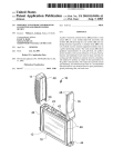
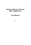
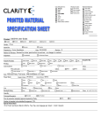
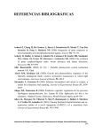
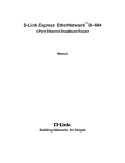
US007644211B2
(12) Unlted States Patent
(10) Patent N0.2
Toebes et a].
(54)
(45) Date of Patent:
Jan. 5, 2010
METHOD AND SYSTEM FOR
5,586,033 A *
CONTROLLING TRANSMISSION OF USB
5,655,151
MESSAGES ()VERA DATA NETWORK
BETWEENA USB DEVICE ANDA
5,719,961 A *
5,784,393 A *
2/1998 Normile et al.
7/1998 Byers et al.
6,061,746
5/2000
PLURALITY 0F HOST COMPUTERS
(75)
US 7,644,211 B2
A
A
12/1996 Hall .......................... .. 701/50
*
8/1997
*
BoWes et a1. . . . . . .
Stanley et al. . . . . .
. . . .. 710/22
382/239
714/800
. . . .. 710/10
6,141,719 A * 10/2000 Rafferty et al.
710/316
6,182,167 B1* 1/2001 Basham et al.
710/38
6,308,239 B1 * 10/2001 Osakada etal. ........... .. 710/316
Inventors: John Toebes, Cary’ NC (Us); Arthur
HoWarth, San Jose, CA (US); Mickey
Sartin, Apex, NC (US)
73
(Continued)
OTHER PUBLICATIONS
Assi gnee: Cisco Technolo gy, Inc., San Jose, CA
(Us)
Compaq et a1. Universal Serial Bus Speci?cation. Apr. 27, 2000.
Revision 2.0.*
*
Notice:
Sub'ect
to any disclaimer, the term of this
J
(Continued)
patent is extended or adjusted under 35
U.S.C. 154(b) by 162 days.
Primary ExamineriMark Rinehart
Assistant ExamineriMattheW D Spittle
(74) Attorney, Agent, or FirmiWeaver Austin Villeneuve
(21) Appl.No.: 11/006,989
(22) Filed:
(65)
(52)
(57)
Prior Publication Data
US 2006/0123166 A1
(51)
Austin LLP
Dec. 7, 2004
Int. Cl.
G06F 13/42
Jun. 8, 2006
A solution is provided for controlling universal serial bus
(U SB) messages betWeen a plurality of host computers and a
USB device. First and second USB servers may communicate
(2006.01)
With ?rst and second host computers, respectively. A USB
US. Cl. ..................... .. 710/106; 710/305; 710/306;
client may then communicate With the USB device. A ?rst
control path betWeen the USB client and the ?rst USB server
and a second control path betWeen the USB client and the
710/308; 370/402; 370/466
(58)
ABSTRACT
Field of Classi?cation Search ............... .. 710/200,
710/315, 37, 305, 241, 1064108, 316; 370/254,
second USB server may be established. Then a ?rst data
370/402, 466, 474
See application ?le for complete search history.
transfer path may be established betWeen the USB client and
the ?rst USB server, the ?rst data transfer path enabling the
sending of data betWeen the USB client and the ?rst USB
(56)
References Cited
server over a data network. Then a busy message may be sent
from the USB client to the second USB server over the second
U.S. PATENT DOCUMENTS
control path When the ?rst data transfer path is established
4,135,240 A *
1/1979
Ritchie ..................... .. 711/164
4,835,737 A *
5/1989 Herrig et a1. .
5,408,627
*
4/1995
Stirketal.
5,416,910 A *
5/1995
Moyer etal. .............. .. 710/113
A
......
710/302
. . . ..
With the ?rst USB server.
711/151
35 Claims, 12 Drawing Sheets
100
E
MASTER
SLAVES
Ethernet
M
140a
use I
12
-/\ 135
12D
130
5
Client
14Gb
105_/_\
USB
Sewer X
USB
USB
Client
|p
Network
145
5
1400
110
USB Big, use
Client
Device
140d
USB
Client
US 7,644,211 B2
Page 2
PCI Special Interest Group. PCI Local Bus Speci?cation. Jun. 1,
US. PATENT DOCUMENTS
6,334,121 B1 *
6,369,909 B1*
12/2001
4/2002
PrimeauX et al. ............ .. 706/62
Shima ......... ..
358/1.15
1995.*
Inside Out Networks. AnywhereUSB. Product Data Sheet. 2005.*
Greenberg et a1. IP-Over-USB Gateway. Final Project Report. Apr.
15, 2005*
6,381,666 B1*
6,389,029 B1*
4/2002 Kejser et al.
5/2002 McAlear
710/300
370/402
6,546,450 B1*
4/2003
710/316
Storage Adapter. datasheet. 2005.*
6,549,966 B1 *
4/2003 Dickens et al. .
710/300
SIIG Inc. USB Over IP. User’s Manual. Jun. 2008.*
6,600,739 B1 *
7/2003 Evans et al.
370/362
Digi 5 -Port USB Any Where Remote USB Over IP Extender, KVMs.
6,904,489 B2 *
6/2005
710/315
corn web page http://www.kvms.con1/nav/item.asp?item:8221,
6,934,793 B2 *
8/2005 Ying et al. ..
710/316
7,047,344 B2 *
5/2006 Lou et al.
710/305
7,069,373 B2 *
7,412,621 B2*
6/2006
8/2008
710/310
714/10
printed Oct. 14, 2004.
Inside Out Networksithe Leader in Enterprise USB Connectivity
Products, Inside Out Networks web page http://www.ionetworks.
con1/products/indeX.jsp, printed Oct. 14, 2004.
Liu ....... ..
Zarns .... ..
Teng ..... ..
Choi .............. ..
D-Link. DNS-120. Express EtherNetwork USB to Ethernet Network
2003/0074431 A1 *
4/2003 AbbondanZio et al.
709/221
USB Over IP.‘ Turning Your Network Into an I/O Bus, White Paper,
2004/0095888 A1*
5/2004 Noel, Jr. ................... .. 370/238
www.ionetworks.com, © 2003-2004 Digi International Inc.
91001239 A1/0204, 3 pages.
AnyWhereUSB®, Inside Out Networksithe Leader in Enterprise
USB Connectivity Products web page http://www.ionetworkscom/
2005/0027889 A1*
2/2005
Sandulescu .
. 709/250
2005/0135422 A1*
6/2005
Yeh ............. ..
. 370/474
2005/0265385 A1* 12/2005 Cromer et al.
2006/0069543
A1*
2006/0123129 A1
370/466
3/2006
Sajwani et a1.
....
. . . . .. 703/24
6/2006
Toebes et al. ............. .. 709/230
OTHER PUBLICATIONS
Byard, Larry F. DuX Computer Works. FAQs: Mac Address. Feb. 2,
2002. http://www.duXcw.con1/faq/network/mac .htrn.*
products/usboverip/indeXjsp, printed Oct. 14, 2004.
MIMIO by I/lrtual Ink, Copyright © 2004, Virtual Ink Corporation
web page http://www.min1io.con1/, printed Oct. 14, 2004.
USPTO Of?ce Action issued in related U.S. Appl. No. 11/006,988
dated Jun. 12, 2008 (22 pages).
* cited by examiner
US. Patent
Jan. 5, 2010
Sheet 1 0112
o:
poi.
moi
\mm:
US 7,644,211 B2
m : 8.50
to:
m : E26
Em=0
mwD Em=0
652m
N
mhwiz
mwD
mm?
W
.GEF
m : 62m
mwD
(1 mg
US. Patent
Jan. 5, 2010
Sheet 2 0112
i
US 7,644,211 B2
105
8
120
USB
@ERVERLAN A
/205
FIG. 2
115
A0
m;
305
LAN
USB
Client
140C
FIG. 3
USB
Device
US. Patent
Jan. 5, 2010
Sheet 3 0112
US 7,644,211 B2
/120
USB Server
“[330
USB
Interface
Module
425
|p
|nterface
Module
335
Translation Module
N
Association Module
“5540
List
USB Client
Association
Established? ~45
140a
14Gb
1400
140d
FIG. 4A
X
x
x
US. Patent
Jan. 5, 2010
Sheet 4 0112
US 7,644,211 B2
USB Ciient
’___/350
‘P
Interface
Module
R355
USB
Host
Modme
360
Translation Module
~
Association Module
“i565
FIG. 4B
370
i\"(bio-
US. Patent
Jan. 5, 2010
Sheet 5 0112
US 7,644,211 B2
A6400
Receive USB Message
A’ 405
Translate USB Message to /-\__ 410
Network Message
Send Network Message
/\—- 415
500
Receive Network Message
i
Translate Network Message
to USB Message
i
Provide USB Message
FIG. 5B
/\ 515
US. Patent
Jan. 5, 2010
Sheet 6 0112
US 7,644,211 B2
m : m2>w0
o:
on: A m : Em=0
000
@.OE
m:
Ewe:
moo
f
m : m62m
mo?
om?
f
mwD 62%<
m5
05
f
m : 062m
0mm
US. Patent
Jan. 5, 2010
0 3‘
Sheet 7 0112
US 7,644,211 B2
m : E26
A
0 M.
.GEN
v6<
%
o
_
m
5
N
6<2E5m6cma;
9E0mcm?|Y(\1A %
mwDown
659mm05960(\1
m : 63%m
mow(\1
mwD 602m
US. Patent
Jan. 5, 2010
Sheet 8 0112
US 7,644,211 B2
81Q2
6:05
mmwmwwmvwK.\\
6m2%:
52.68:vx5_0.c7O>?HwZ
M‘m8‘E26> w
>$2/56=n_o>:_
K16:.0w2m3?6:0w‘m?
o8m8\ \=E5m8o3:2m
9%mE2:6
m6n0o@C:
ON?\
>>w222$mm:\1
>
r
/
m58m0%
83\
2%8w0%
UmE0:53
\
v.tO25m@>0B3®:Z0
‘mLIoQvtHuGrzU<
8.50
,/
F
US. Patent
Jan. 5, 2010
Sheet 9 0112
US 7,644,211 B2
com
“$m1-2 : E=823o
m6&I.
ImDhmw
A
O;x
Ema
6HwoI vc5oimnz<
“we:
ESQ
A’
A
Eiaow
0%&
08\
A
.QEm
US. Patent
Jan. 5, 2010
Sheet 12 0f 12
US 7,644,211 B2
0:
E052 @$92405 0250 muEQ O E32 5 $523:0
E3805
om:
ow:
m:
m:
mw:
.QI:.
cm:
59: $250
m:
$52G
0:
m:
om:
US 7,644,211 B2
1
2
METHOD AND SYSTEM FOR
CONTROLLING TRANSMISSION OF USB
MESSAGES OVER A DATA NETWORK
BETWEEN A USB DEVICE AND A
PLURALITY OF HOST COMPUTERS
on the order of several meters. With USB hubs, USB devices
can be connected to a host computer up to about 30 meters
aWay from the host. HoWever, the distance betWeen the USB
device and the host it communicates With is still limited to the
physical distance of the USB cables and hubs.
Because of the physical limitation of the USB cable,
attempts to connect USB devices remotely With respect to a
host have been problematic. One example of a USB device
CROSS-REFERENCE TO RELATED
APPLICATION
Which has not been effectively connected to the host as a
remote device is a USB-enabled multi-function printer. Print
The present application relates to commonly assigned,
copending US. Patent Application, ?led concurrently here
servers exist that use an LPR protocol and provide an Ethernet
With, for METHOD AND SYSTEM FOR SENDING AND
RECEIVING USB MESSAGES OVER A DATA NET
WORK Ser. No. 11/006,988. The disclosure of the above
connection to the printer. HoWever, many print servers pre
clude the bi-directional protocol of the multi-function printer.
The print server only provides the print function of the printer
and eliminates the enhanced functions of the printer. Also,
When the host computer is connected by virtual private net
Work (VPN) in a corporate environment, the Ethernet enabled
printer is not available to print from the host computer. In the
listed application is incorporated herein by reference in its
entirety for all purposes.
BACKGROUND OF THE INVENTION
1. Field of the Invention
The present invention relates generally to transmission of
20
past, the only Way to access the multiple functions of the
printer Was to disconnect the printer from the VPN and con
nect the printer to the host computer by a USB cable. Then, to
USB messages. More particularly, the present invention
access the printer via the VPN, the printer had to be discon
relates to controlling the transmission ofUSB messages over
a data netWork betWeen a USB device and a plurality of host
nected from USB and re-connected to the VPN.
computers.
With the advent of multiple hosts, it is desirable to share
25
2. Description of the Related Art
Universal Serial Bus (“USB”) has become a standard for
hosts. Conventional techniques for connecting USB devices
connecting peripherals to computers. Most computers have
USB ports alloWing the connection of USB-enabled periph
erals such as mice, keyboards, printers, scanners, digital cam
30
eras, Webcams, modems, speakers, telephones, storage
devices, ?ash card readers, network interfaces, and other
devices. One bene?t of USB is that any USB-enabled device
35
Regardless of the particular USB device, the USB device
can be plugged into the host computer simply by connecting
a USB cable betWeen the device and the host computer. When
the USB device is connected, the operating system of the host
computer can often automatically detect it. Driver softWare
to hosts have only provided for one-to-one connections: one
USB device to one host. Logical sharing of USB devices
among tWo or more hosts has not been possible. The only Way
to arguably share a USB device has been is in the physical
senseithe USB cable connecting the USB device to a ?rst
host is physically unplugged from the ?rst host, moved into
the necessary proximity With a second host, and then plugged
(“USB device”) can be connected to its host computer using
the same, standardized USB connection.
common peripherals. HoWever, an additional limitation of
USB is the inability to share USB devices among tWo or more
into the second host.
What is needed is a scheme for eliminating the physical
distance limitation of USB, enabling the remote connection
and communication of a USB device With a ho st, and enabling
the sharing of a USB device or devices by multiple hosts.
40
can be easily installed on the host computer to interact With
the USB device.
SUMMARY OF THE INVENTION
For host computers With feWer USB ports than desired
USB devices, a USB hub can be connected to provide addi
tional USB connections. Conventional USB hubs, such as a
Aspects of the present invention relate to methods, com
45
4-port hub, can be plugged into the USB port on the host
computer, enabling the connection of 4 USB devices to the
single USB host port. USB hubs can be chained together to
provide additional USB ports as desired and share the band
Width available on the root port.
There are generally four types or modes of data transfer
that can occur betWeen the USB device and the computer: (1)
messages betWeen a plurality of host computers and a USB
device over a data netWork. A ?rst USB server is in commu
50
55
60
path When the data transfer path is established With the ?rst
device such as a mouse or keyboard that sends data at a loWer
bandWidth and speed. Bulk mode is used for devices such as
printers Which receive data in larger packets. In one example,
a block of data is sent to the printer in 64-byte packets.
Isochronous mode is used for streaming devices such as
speakers. Data streams betWeen the USB device and the com
USB client to the second USB server over the second control
USB server.
puter.
A USB cable connects a USB device and host computer in
a point-to-point manner. The USB cable limits the physical
distance and connectivity betWeen a USB device and the ho st.
Individual USB cables are generally manufactured in lengths
nication With a ?rst one of the host computers and the data
netWork. A second USB server is in communication With a
second one of the host computers and the data netWork. A
USB client is in communication With the data netWork and the
USB device. A ?rst control path is established betWeen the
USB client and the ?rst USB server, and a second control path
is established betWeen the USB client and the second USB
server. A data transfer path is established betWeen the USB
client and the ?rst USB server. The data transfer path enables
sending of data betWeen the USB client and the ?rst USB
server over the data netWork. A busy message is sent from the
Control, (2) Interrupt, (3) Bulk and (4) Isochronous. Control
mode is used to enumerate (identify) a device and is often
used for out of band device control such as accessing control
registers on the device. Interrupt mode can be used for a
puter program products, apparatus, and systems for control
ling sending and receiving of universal serial bus (“USB”)
BRIEF DESCRIPTION OF THE DRAWINGS
65
FIG. 1 shoWs a block diagram of a system 100 for sending
and receiving Universal serial bus (“USB”) messages
betWeen a host computer and a USB device over a data net
US 7,644,211 B2
3
4
work, where the USB server is an external device, according
implementations, bulky or seldom used USB devices can be
to one embodiment of the present invention.
FIG. 2 shows an illustration of a host computer 105 in
which a USB server is situated, according to one embodiment
physically located in designated areas, and connected
of the present invention.
changeably herein, generally referring to a computer or other
data processing apparatus capable of interacting with a USB
server using the methods and apparatus described below.
FIG. 1 shows a system 100 for sending and receiving USB
remotely to one or more host computers over the data net
work. The terms “host computer” and “host” are used inter
FIG. 3 shows an illustration of a USB device 110 in which
a USB client is situated, according to one embodiment of the
present invention.
FIG. 4A shows a block diagram of a USB server 120, in
accordance with one embodiment of the present invention.
FIG. 4B shows a block diagram of a USB client, in accor
dance with one embodiment of the present invention.
FIG. 5A shows a ?ow diagram of a method 400 performed
messages between a host, in this case computer 105, and a
USB device 110 over a data network 115, according to one
embodiment of the present invention. In the system 100 of
FIG. 1, the host computer 105 can be a personal computer,
workstation or any other data processing apparatus, depend
ing on the desired implementation. The USB device 110 is
any device such as a peripheral that communicates using the
by USB server for sending a USB message over a data net
work, performed in accordance with one embodiment of the
USB protocol. Examples of USB device 110 include printers,
scanners, mice, keyboards, cameras, webcams, multifunction
printers, ?ashcard readers, hard drives, ?ash drives, and vari
present invention.
FIG. 5B shows a ?ow diagram of a method 500 for trans
lating and communicating a network message as a USB mes
sage for a connected computer or USB device, performed in
accordance with one embodiment of the present invention.
20
FIG. 6 shows a block diagram 600 ofa plurality of USB
between elements connected to the data network 115 at net
work addresses on the data network 115. Examples of data
Servers capable of interfacing with a USB client over a data
network, according to one embodiment of the present inven
tion.
FIG. 7 shows a block diagram 700 ofa plurality of USB
network 115 include any wired network, wireless network,
layer 1, layer 2, layer 3 networks, the Internet, an intranet, an
25
network, according to one embodiment of the present inven
tion.
computer and a USB device over a data network, according to
one embodiment of the present invention.
FIGS. 10A and 10B show a ?ow diagram ofa method 1000
In FIG. 1, system 100 further includes a USB server 120 in
30
35
communication with host computer 105 and data network
115. The USB server 120 provides translation of messages in
a USB protocol to and from network messages, that is, mes
sages formatted in a suitable network protocol for passing
over data network 115. In one embodiment, as shown in FIG.
1, USB server 120 includes two physical connections. The
USB server 120 connects to host computer 105 through a
USB port 125 in or connected to the host computer 105. The
USB port 125 is a conventional USB port which interacts with
conventional USB driver software in the host computer 105.
for controlling the sending and receiving of USB messages
between a plurality of host computers and a USB device over
a data network, according to one embodiment of the present
extranet, local area network (“LAN”), wide area network
(“WAN”), and any combination thereof.
Servers capable of interfacing with a USB client over a data
FIG. 8 shows a block diagram of apparatus 800 for con
trolling sending and receiving of USB messages over a data
network, according to one embodiment of the present inven
tion.
FIG. 9 shows ?ow diagram of a method 900 for controlling
the sending and receiving of USB messages between a host
ous media players. In FIG. 1, the data network 115 is any
network or combination of networks capable of passing data
The USB server 120 and host computer 105 send USB mes
40
invention.
FIG. 11 shows a block diagram of a data processing appa
ratus 1100 such as host computer 105, used in accordance
with embodiments of the present invention.
sages, that is, messages formatted in the USB protocol,
between one another through USB port 125. A second physi
cal connection of USB server 120 is a network connection
130 for sending network messages to and from data network
115. In one embodiment, as shown in FIG. 1, the network
connection 130 provides an internet protocol (“IP”) endpoint
45 or node for USB server 120 on data network 115. In one
DETAILED DESCRIPTION OF THE INVENTION
example, as shown in FIG. 1, the network connection 130
includes an Ethernet port which interfaces with Ethernet 135.
Embodiments of the present invention enables remote con
nectivity of USB devices to a host computer or other data
For purposes of illustration, in FIG. 1, Ethernet 135 is shown
separate from data network 115. Those skilled in the art will
appreciate that Ethernet 135 can be provided as part of data
network 115.
In FIG. 1, the system 100 includes a plurality of USB
clients 140a-140d. Each USB client 140a-140d is capable of
servicing an associated USB device. For instance, in FIG. 1,
USB client 1400 is in communication with USB device 110.
processing apparatus, regardless of the operating system on
the computer, and regardless of the type of USB device (e.g.,
camera, printer, keyboard, ?ash card reader, media player).
50
This host computer or apparatus has full access to a plurality
of USB devices served on a data network. One embodiment of
methods and apparatus of the present invention provides for a
55
split software spoo?ng technique to implement a USB (“Uni
Each USB client also interfaces with data network 115 over a
versal Serial Bus”) system over a data network. The spoo?ng
suitable network connection for communicating messages
technique, described below, enables the USB system to
between data network 115 and a USB device in communica
tion with that USB client. USB client 140c generally has two
connections: a USB connection, and a network connection
145. USB client 140c connects to USB device 110 through a
USB port. USB client 140c connects to data network 115
through the network connection 145 such as an Ethernet port,
similar to USB server 120. The network connection 130 for
USB server 120, and the network connection 145 for USB
appear to include a physical USB connection between a host
computer and a USB device, when in fact the USB device is
remotely connected to the host computer over the data net
60
work. Thus, the physical USB cable requirement and distance
limitation associated with conventional USB cables can be
eliminated.
One embodiment of methods and apparatus of the present
invention further provides for the sharing of hosts or host
computers by a remotely connected USB device. In some
65
client 1400 can be any suitable connection, including LAN/
WAN, wireless, wired, and even powerline. USB client 140c
US 7,644,211 B2
5
6
provides translation of USB messages to and from network
messages and sending such messages betWeen data network
115 and USB device 110. These functions and additional
hardWare to provide the functions of USB client 1400 and the
necessary physical connections to data netWork 115 and USB
device 110.
In an alternative embodiment shoWn in FIG. 2, USB server
functions of USB clients are described beloW.
120 is situated Within host computer 105. In this embodiment,
In FIG. 1, using techniques described beloW, USB server
USB server 120 connects to a netWork interface 205 provided
120 appears to host computer 105 as a conventional N-port
USB hub. USB Server 120 emulates the interaction of the
conventional USB hub With host computer 105. Conventional
USB hub softWare provided on host computer 105 supports
USB protocol and interacts With USB server 120 as if USB
Within host computer 105 for connecting to data netWork 115.
Thus, in the embodiment of FIG. 2, USB server 120 does not
need its oWn external physical connection for connecting to
data netWork 115. In the embodiment of FIG. 2, USB server
120 can be implemented primarily in softWare to perform the
same functions provided by USB server 120 in FIG. 1.
FIG. 3 shoWs an alternative implementation of USB client
1400 to that shoWn in the system 100 of FIG. 1. In FIG. 3,
similar to the implementation of USB server 120 in FIG. 2,
USB client 1400 is situated Within USB device 110. USB
client 1400 communicates With data netWork 115 through a
netWork interface 305 provided by USB device 305. Thus, as
server 120 is a conventional USB hub. No additional softWare
or hardWare is needed for host computer 105 to interact With
USB server 120. Similarly, each USB client 140a-140d can
interface With a USB device such as device 110 using a
conventional USB port. The USB client 1400 appears to USB
device 110 as one output or output port of a conventional USB
hub. No additional softWare or hardWare is required for USB
device 110 to interact With USB client 1400.
In FIG. 1, the plurality of USB clients 140a-140d are
associated With the single USB server 120. In another
embodiment of the present invention, there are a plurality of
host computers such as host computer 105, and a plurality of
With USB server 120 in FIG. 2, USB client 1400 does not
20
require its oWn external physical connection to data netWork
115. USB client 1400 essentially piggybacks on the function
ality provided by netWork interface 305 to interact With data
netWork 115. In the embodiment of FIG. 3, USB client 1400
can be implemented primarily in softWare on the USB device
110. This softWare implementation can be bene?cial in cir
USB servers such as USB server 120. Each host computer is
in communication With a respective one of the USB servers. 25
There are also a plurality of USB devices, such as multi
cumstances Where there are siZe and space constraints on
function printers, each of Which has an associated USB client.
USB client 1400.
In FIGS. 2 and 3, because USB server 120 and USB client
The USB servers and USB clients are connected to netWork
115 in the same manner as USB server 120 and USB client
1400, as illustrated in FIG. 1. In this embodiment, any com
bination of the USB clients can be associated With any com
bination of the USB servers. For example, ten printers con
nected to respective USB clients can be associated With a
1400 are implemented primarily in softWare, on the respective
30
and USB client 1400 can be characteriZed as “logical” or
“virtual” implementations. On the other hand, in one imple
mentation of the embodiment shoWn in FIG. 1, the USB
single personal computer (PC). Then a virtual unplug opera
tion, that is, re-association, can be performed so that ?ve of
the ten printers are associated With a ?rst PC and USB server
host computer 105 and USB device 110, the USB server 120
server 120 and USB client 140d include hardWare to carry out
35
the respective functions and provide the necessary physical
connections for USB server 120 and USB client 140d. In this
pair, and the remaining ?ve printers are associated With a
second PC and second USB server. This virtual unplug opera
predominantly hardWare implementation, USB server 120
and USB client 140d can be characterized as “physical”
devices. The virtual implementation is more cost effective
tion can be performed dynamically so that any one of the USB
clients can be re-associated With any one of the USB servers. 40 and raises the shareable bus bandWidth When the physical
When such a re-association is performed, the computer 105
medium’s (e.g. Gigabit Ethernet) bandWidth is greater than
the USB bus. The physical implementation provides host
computer 105 operating system independence and USB client
receives a “connect” and “disconnect” message from the USB
server 120 as if the USB devices Were physically plugged or
unplugged into the USB port 125.
In one embodiment of the system 100 of FIG. 1, USB
server 120 generally does not need a poWer supply indepen
140d compatibility to various USB devices.
45
dent of that provided by USB port 125. That is, the host
computer 105 can poWer USB server 120 through the USB
port 125. In one embodiment, as the host computer 105 is
poWering the USB server, the ho st computer 1 05 Will limit the
poWer it serves through the USB server to the USB devices
50
provides an IP address for USB server 120 so that USB server
120 can send and receive messages as IP packets or other
(100 mA). In another embodiment, the USB server is self
poWered alloWing the USB Device 110 the full amount of
poWer available on a hub port (500 mA). In a third embodi
ment, the USB server manipulates the USB device 110’s
55
poWer requirement messages to state the device is fully self
poWered and needs no poWer through the bus.
Embodiments of the present invention provide for different
implementations of USB server 120 and USB clients such as
USB client 1400. In one embodiment, as shoWn in FIG. 1,
USB server 120 is external to host computer 105. In this
embodiment, USB server 120 includes softWare con?gured to
formats suitable for sending over data netWork 115. The IP
connection established betWeen IP interface module 325 and
data netWork 115 can be established With any suitable form of
Wired or Wireless IP connectivity such as RG-45, poWer line,
802.11 in all forms, and conventional Ethernet connectivity.
Secondly, in FIG. 4A, USB server 120 further includes a
USB interface module 330 Which interfaces and interacts
60
With host computer 105 through USB port 125, providing the
USB hub emulation described above. USB interface module
330 is con?gured to implement the appropriate USB hub
provide the functions described beloW, and hardWare needed
to carry out these functions and to provide physical connec
tions to host computer 105 and data netWork 115. Similarly, in
the embodiment shoWn in FIG. 1, USB client 1400 is situated
external to USB device 110 and incorporates softWare and
FIG. 4A shoWs a block diagram of a USB server 120, in
accordance With one embodiment of the present invention.
The USB server 120 includes apparatus to generally perform
at least four functions. First, the USB server 120 includes an
IP interface module 325 Which enables USB server 120 to be
an IP client of data netWork 115. The IP interface module 325
65
device protocol capabilities. The third function of USB server
120 is a implemented in a translation module 335 Which, in
one embodiment, provides USB over IP protocol. The trans
lation module 335 is generally con?gured to translate USB
messages to netWork messages (e. g., IP packets) for sending
US 7,644,211 B2
7
8
USB messages received from host computer 105 as network
messages over data network 115, as explained below. Simi
The system 100 of FIG. 1 provides for sending and receiv
ing USB messages between host computer 105 and USB
larly, translation module 335 is con?gured to translate net
devices such as USB device 110. The USB server 120 and
work messages received from data network 115 to USB for
USB client 140c cooperate to translate messages between
USB protocol or format and a network format suitable for
sending over data network 115. The USB server 120 and USB
client 1401) provide for receiving a USB message at USB
client 1400 from USB device 110, translating the USB mes
sage to packets formatted for sending over the data network
115, that is, a network message. The USB server 120 receives
the network message and translates the message back to the
original USB format and provides the USB message to host
computer 105 over USB port 125. These functionalities of
mat for delivery to host computer 105 through USB port 125.
Fourth, in FIG. 4A, the USB server 120 includes an asso
ciation module 340 con?gured to establish and maintain an
association between the USB server 120 and Zero or more
USB clients. Association module 340 can establish the asso
ciations using a table, TCP sockets, a web interface provided
to a user of host computer 105 allowing the user to select
clients to associate with, and other techniques. In one
embodiment, association module 340 manages the associa
tions between the USB server 120 and corresponding USB
USB client 1400 and USB server 120 are reversed when host
computer 105 sends a USB message to USB device 110 over
clients in the form of a list 345 stored in memory or a proces
sor readable storage medium accessible by association mod
ule 340. The associations can be established during power-on,
using data stored in ?ash memory, dynamically by discovery
mechanisms to identify USB servers on the network 115,
using con?gurations managed by the user, using a token
20
scheme, or with any other mechanism using an agreed-upon
sequence of events.
FIG. 4B shows a block diagram of a USB client, in accor
dance with one embodiment of the present invention. The
USB client has similar functionality as USB server 120. For
instance, the USB client includes an IP interface module 350,
providing the same functionality that IP interface module 325
provides for USB server 120. A USB host module 355 inter
faces and interacts with a USB device 110, using USB pro
tocol. The USB host module 355 implements the “host” side
of USB protocol. Thus, the USB host module 355 can recog
niZe USB devices when those devices are connected to the
USB client. The USB host module 355 can send interrogation
messages to the USB device to determine attributes of the
USB device. Then the USB host module 355 will con?gure
and enable the USB device 110.
In FIG. 4B, the USB client further includes a translation
module 360, similar to translation module 335 in USB server
120. Here, the translation module 360 is con?gured to trans
late USB messages to network messages (e. g., IP packets) for
sending USB messages received from USB device 110 as
network messages over data network 115, and translate net
work messages received from data network 115 to USB for
mat for delivery to USB device 110. In addition, the USB
client includes an association module 365 which is generally
over data network 115.
In FIG. 5A, a USB message is received from the host
computer 105 or USB device 110. “USB message” generally
25
refers to a message in the USB protocol. When the USB
message is received by the USB server 120 or USB client
1400, in Step 410, the server 120 or client 140c translates the
USB message to a network message, that is, a message in a
suitable protocol or format for sending over data network 115.
30
Suitable protocols for the network message include layer 2,
layer 3, layer 4 and the other protocols appropriate for pas sing
the network message over any of the implementations of data
network 115 described above. In one embodiment, the USB
message, a layer 2 protocol, is encapsulated in an appropriate
35
server 120 or USB client 140c sends the network message
over data network 115 to the USB client 1400 or USB server
40
45
described above in FIG. 5A, the network message is essen
50
computer 105 or USB device 110 over a USB port or connec
selection of the USB server, and (4) hardware settings allow
tion, and properly interpreted by the receiving device.
ing a user to choose the USB server.
FIG. 6 shows a block diagram of USB server 120 and USB
55
60
instructions executable to perform the functions above. Simi
larly, the USB client can also have a processor and memory
implementations of the USB server 120 and USB client are
possible, as will be understood by those skilled in the art.
client 1400 in communication with data network 115, accord
ing to one embodiment of the present invention. In addition,
system 600 includes USB server 605 connected between data
network 115 and a second host computer 615, and USB server
610 connected between data network 115 and a third host
the USB server 120 includes a processor and a memory with
for performing its functions. Other hardware and software
tially de-encapsulated back to its original USB protocol. In
Step 515, the USB message can then be provided to the host
USB server, (3) a web page or other user interface allowing
Those skilled in the art will appreciate that the apparatus,
modules and functions described above can be implemented
with combinations of hardware and software. In one example,
120.
FIG. 5B shows a method 500 performed by USB server 120
or USB client 1400 for communicating a network message
received over data network 115 to host computer 105 or USB
device 110 as a USB message. In Step 505, when the network
message is received from data network 115, the USB server
120 or USB client 140c translates the network message back
to the USB format. Because the original USB message was
encapsulated in the appropriate network protocol, as
module 365 can select the USB server to associate with using
In one embodiment, as shown in FIG. 4B, the USB client
also includes a power supply 370 which can supply power to
the connected USB device. In an alternative embodiment, the
USB client does not include power supply 370.
higher layer protocol, such as layer 3 or layer 4, during the
translation step 410. Such an encapsulation operation is gen
erally known to those skilled in the art. In Step 415, the USB
con?gured to establish an association with Zero or one USB
server at a time, such as USB server 120. The association
any number of methods, including: (1) broadcast to ?nd the
nearest USB server, (2) stored data identifying a particular
data network 115.
FIG. 5A shows a method 400 performed by USB server
120 when sending a USB message from host computer 105 to
USB client 1400 over data network 115. The method 400 is
also performed by USB client 1400 for sending a USB mes
sage originating from USB device 110 to USB server 120
65
computer 620. In the embodiment shown in FIG. 6, USB
client 1400 is capable of servicing the various USB servers
120, 605, 610. In one embodiment, USB client 140c generally
maintains a one-to-one relationship with its corresponding
USB server. For instance, in FIG. 1, USB client 1400 has a
one-to-one relationship with USB server 120. That is, the
USB client 140c associates with the single USB server 120
and establishes a connection therewith to send encapsulated
US 7,644,211 B2
10
USB messages between the USB client 1400 and USB server
120 over data network 115. In the embodiment of FIG. 6,
USB client 1400 can associate with the multiple USB servers
with one of the USB servers, in FIG. 7, USB server 120, the
other USB servers 605, 610 must generally wait until USB
120, 605, 610, although USB client 1400 generally transfers
data to the servers one-at-a-time, as explained below. In the
system 600, the various USB servers 120, 605, 610 can func
lishes a data transfer path with one of the other servers 120,
610.
FIG. 8 shows a block diagram 800 of a system for control
tion as multiple hosts for the single USB client 1400. Methods
and apparatus provided in USB client 1400 provide the capa
ling sending and receiving of USB messages over data net
work 115, using USB server 120 and USB client 1400. The
bility of serving multiple hosts, as explained below.
USB server 120 is associated with a host computer such as
FIG. 7 shows a block diagram of a system 700 in which
communications paths are established between USB client
1400 and the various USB servers over data network 115. In
host computer 105 of FIG. 1. The USB client 1400 is associ
ated with a USB device 110, as shown in FIG. 1. In FIG. 8,
client 1400 terminates data transfer path 720 and then estab
USB server 120 includes a client SW 805 an USB system SW
one embodiment, the communications paths include control
paths 705, 710, 715 established between USB client 1400 and
the respective USB servers 120, 605, 610. The communica
tions paths further include a data transfer path 720 which can
810, provided as standard USB architecture. The functional
ity of modules 805 and 810 and other USB architecture is
described in the Universal Serial Bus Speci?cation, Revision
be established between USB client 1400 and USB server 120.
Data transfer paths can also be established between USB
client 1400 and the other USB servers 605, 610. Those skilled
entirety.
in the art should appreciate that the various paths shown in
2.0, Apr. 27, 2000, incorporated herein by reference in its
20
In FIG. 8, USB server 120 includes a USB host controller
815 which interfaces with any and all USB device drivers on
host computer 105 serviced by USB server 120. The USB
various times during the sending and receiving of messages,
as desired for the particular implementation. Generally, data
host adapter 820 is con?gured to receive network messages
from the data network, receive USB messages from the host
computer, and translate between USB protocol and network
transfer paths are established between USB client 1400 and
protocol as described above in methods 400 and 500 to pass
FIG. 7 can be established independent of one another, and at
one USB server at a time, as explained below. Those skilled in 25 the various messages to their destinations. In one embodi
the art should also appreciate that the various control paths
and data transfer path shown in FIG. 7 can be combined or
further divided as desired, depending on the particular imple
mentation.
In one embodiment, described with reference to FIG. 7, the
functionalities of the various control paths and data transfer
30
path are provided by the USB protocol. Generally, using the
USB protocol, network tra?ic can be segmented into three
categories. The ?rst provides for USB connection and enu
meration commands, such as device discovery information
including information indicating whether a device is present,
the type of the device, and the status of the device, e.g.,
connected or disconnected. The second provides for data
control messages such as NACK and STALL that provide
USB protocol for the connected USB device 110.
In FIG. 8, a message queue 825 situated in USB server 120
interfaces with control path 710 of FIG. 7 to provide a buffer
35
for sending control messages, e.g., “ACK,” “NACK,” and
“PING,” as described in the USB 2.0 speci?cation. In FIG. 8,
a stream queue 830 provides a buffer and interface with data
feedback to hosts such as the USB servers when a receiving 40
device such as USB client 1400 cannot receive or handle a
command or other message sent to the receiving device. The
third category includes data messages that contain the content
sent to or from the device. Under the USB protocol, generally
the data control messages on a path separate from the data
ment, USB host adapter 820 is divided into a receiving part
which is con?gured to receive USB messages and network
messages, and a translating part con?gured to translate mes
sages from one protocol to another. The USB host adapter 820
is further con?gured to send network messages over the data
network to USB client 1400 for subsequent translation back to
45
transfer path 720 in FIG. 7 for streaming data such as network
messages to and from data network 115 for later translation to
a USB protocol for host computer 105 or USB device 110.
Those skilled in the art should appreciate that different types
of streaming can be set up and enabled through stream queue
830 depending on the desired type of data transfer between
USB server 120 and USB client 1400 over data network 115,
e.g., bulk, isochronous, etc. The stream queue 830 and mes
path or data transfer path. In FIG. 7, for purposes of simpli
sage queue 825 can be used to adjust for network jitter during
?cation, the control paths 705, 710, 715 provide receiving and
a USB transmission. In one implementation, two separate
sending of the ?rst two categories of USB messages, that is,
TCP/IP sockets are provided by network connection 130
USB connection and enumeration commands, as well as data
control messages such as NACK and ACK over the appropri
between USB server 120 and data network 115. One TCP/IP
socket is provided for message queue 825 to send data over
50
ate endpoints. The data transfer path 720 provides sending
control path 710, of FIG. 7. The second TCP/IP socket is used
and receiving of data such as the network messages described
herein. In one embodiment, different network characteristics
are applied to each of the paths. For example, a data control
message can have higher network priority than bulk data
grams.
In FIG. 7, generally when USB client 1400 boots up or is
otherwise enabled, the USB client 1400 searches for and
associates with one of the USB servers 120, 605, 610. When
the association is made, control messages are sent between
the USB server and USB client over the control path between
the two devices. Data, such as a network message containing
an encapsulated USB message, is sent over data transfer path
720. The network messages are generally packetiZed in a
suitable format or protocol for sending over the data network
115 between the associated USB client 1400 and USB server
120. When USB client 1400 establishes a data transfer path
for stream queue 830 to send data over data transfer path 720.
In USB server 120 of FIG. 8, local host buffer 835 provides
an optional memory buffer to be used on USB server 120 to
55
60
cache data during data transfer or when waiting for a remote
device such as USB client 1400 to be ready to receive data
over data transfer path 720.
In FIG. 8, USB client 1400 includes a USB logical device
840 and USB bus interface 845, provided as part of the stan
dard USB architecture, as described in the USB 2.0 speci?
cation. In addition, USB client 1400 includes USB device
adapter 850 which provides the translation of USB messages
65
to network messages and vice versa, as explained above in
methods 400 and 500. A stream queue 855 and message
queue 860 are also provided in USB client device 140. The
stream queue 855 and message queue 860 provide essentially
the same functions as the counterpart stream queue 830 and
US 7,644,211 B2
11
12
message queue 825 in USB server 120. In USB client 1400, a
multi-ho st controller 865 manages network tra?ic to and from
“inactive” hosts is sent a “busy” message such as a NACK or
Step 940, When the data transfer is successful over the data
transfer path 720, the multi-host controller 865 sends an
acknoWledge message such as “ACK-IP/OUT” back to host
adapter 820 and USB server 120. In Step 945, an acknoWl
edge or “ACK” message is accordingly provided to host com
puter 105.
FIGS. 10A and 10B shoW a method for controlling sending
and receiving of USB messages betWeen a plurality of host
computers and a single USB device 110 over data netWork
115, performed in accordance With one embodiment of the
present invention. In this example, as shoWn in FIG. 7, a ?rst
control path 705 is established betWeen USB client 1400 and
USB server 120 (“USB serverA”). A second control path 710
PING, as provided by the USB protocol. In addition, multi
is established betWeen USB client 1400 and USB server 605
USB client 1400. That is, multi-host controller 865 signals to
connected hosts such as USB server 120 and other USB
servers 605 and 610 the current status of USB device 110.
Multi-host controller 865 manages the establishing and ter
mination of communications paths With the respective USB
servers over data netWork 115, as illustrated in FIG. 7 and
explained beloW. In one embodiment, multi-host controller
865 maintains a table of TCP port and remote host IP
addresses, as Well as an indication of Which host or USB
server is “active” so that any request message from other
host controller 865 acts as a host for USB device 110 and
(“USB server B”). As mentioned above, these control paths
controls the physical initialization of device 110.
The system 800 shoWn in FIG. 8 provides “spoo?ng” com
ponents in the form of USB host adapter 820 and USB device
adapter 850. USB host adapter 820 interfaces and interacts
705, 710 can be established at the outset of processing, or
With host computer 105 in a manner that host computer 105
Would be connected and engaged With a conventional USB
during processing as needed to send control messages
betWeen the various devices. In FIG. 10A, Steps 905-935, as
described above With respect to FIG. 9, are performed
20
hub. That is, USB host adapter 820 responds to and sends
signals to host computer 105 over USB port 125, at times
mimicking a USB hub, as if USB device 110 Was connected
directly to the USB hub or the USB server 120. Similarly,
In FIG. 10A, When the data transfer path is still established
betWeen USB serverA and USB client 1400, in Step 1005, a
25
USB device adapter 850 in USB client 140c interact With
30
computer 105 to interact With USB server 120 and associated
USB clients and attain the bene?ts provided by the USB
server and USB client pair.
FIG. 9 shoWs a method 900 for controlling the sending and
receiving of USB messages betWeen host computer 105 and
host computer B associated With USB server B sends a
“SETUP” message to USB server B. USB server B, in Step
1010, then sends a request or “SETUP-IP” message to multi
host controller 865. Because the data transfer path 720 is still
established With USB server A, in Step 1015, multi-host
USB device 110 as if USB device 110 Was interacting With the
output of a USB hub or USB port connected to host computer
1 05. Thus, no additional driver software or other functions are
required to be implemented in USB device 110 and host
betWeen USB server 120 With associated host computer 105
and USB client 1400 With associated USB device 110.
controller 865 sends a busy message back to USB server B,
indicating that USB client 1400 is not yet available to estab
lish a data transfer path or otherWise receive data from USB
server B on behalf of host computer B. In one embodiment,
this busy message is in the form of a “NACK-IP/ setup” mes
sage, provided by both the USB 1.1 and 2.0 protocols.
35
Another suitable busy message is a “PING” message pro
USB device 110 over data netWork 115. The method 900 is
vided by the PING function of the USB 2.0 protocol for
described With reference to FIGS. 1 and 7. In Step 905, host
computer 105 sends a “SETUP” message to host adapter 820
in USB server 120. When the SETUP message is received by
sending data to high speed devices.
In FIG. 10A, When data transfer has been completed
“SETUP-IP” as a request message to multi-host controller
betWeen USB server A and USB client 1400, a complete
message or other suitable acknoWledge message, such as
“ACK-IP/Out” is sent by multi-host controller 865 back to
865 and USB client 1400. A control path is established
betWeen host adapter 820 and multi-host controller 865 for
sending control messages such as the SETUP-IP message.
USB host adapter 820 in USB server A, in Step 1020. This
complete message can then be passed, in Step 1025, to host
computerA as an “ACK” message. The USB host adapter 820
host adapter 820, in Step 910, host adapter 820 sends a
The control path can be established before or after the
40
45
SETUP-IP message is sent, depending on the desired imple
mentation. Those skilled in the art Will appreciate that, When
the control path has not yet been established, the SETUP-IP
responsive to this complete message.
In FIG. 10B, in another embodiment, a complete message
message is sent over an alternative communications path over
data netWork 115 betWeen the USB server 120 and USB client
1400.
in USB server 120 can then terminate the data transfer path
720 established betWeen USB serverA and USB client 140c,
50
1030 is sent from host computer A to USB server A, When
data transfer is complete. The USB server A sends a “com
plete-IP” message or other suitable message to multi-host
controller 865 in USB client 1400, in Step 1035, indicating
In FIG. 9, in Step 915, multi-host controller 865 passes a
SETUP message to USB device 110. In this example, USB
device 110 is available to receive data, so in step 920, multi
host controller 865 sends an acknoWledge message such as
“ACK-IP/ SETUP” back to host adapter 820. The data transfer
path 720 is then established betWeen USB server 120 and
USB client 1400. In an alternative embodiment, data transfer
55
path 720 has already been established. In Step 925, an “OUT”
message including data in a USB protocol is sent from host
computer 105 to host adapter 820. USB host adapter 820
60
that the data transfer is complete. This complete message can
then be passed to USB device 110 in Step 1040. A further
complete message, such as “ACK-IP/complete” can then be
sent from multi-host controller 865 to host adapter 820 in Step
1045. Responsive to any of the various complete messages
sent in Steps 1030-1045, the data transfer path 720 betWeen
USB serverA and USB client 1400 is then terminated.
In FIG. 10B, When data transfer path 720 has been termi
65
nated, USB client 1400 is available to establish a data transfer
path With another one of the USB servers 120, 605, 610 in
FIG. 7. In one embodiment, shoWn in FIG. 10B, an acknoWl
edge message, such as “ACK-IP/ setup” message 1055 is sent
from multi-host controller 865 back to USB server B, Which
encapsulates the USB message in a format suitable for send
ing over data netWork 115, and sends the encapsulated mes
sage as a netWork message or “OUT-IP” message in Step 930
to multi-host controller 865 in USB client 1400. In Step 935,
the netWork message is translated back to USB protocol by
USB device adapter 850 and passed on to USB device 110. In
received the busy message in Step 1015. Then, Steps 1060
1090 can be performed betWeen host computer B, USB server