
1
OPERATING INSTRUCTIONS For the Model CT-7500 A Digital Circuit-Breaker Analyzer Manufactured by Vanguard Instruments Co., Inc. 1711 Grevillea Ct. Ontario, California 91761 TEL: (909) 923-9390 FAX: (909) 923-9391 Jan 2001 Rev 2 MODEL CT-7500 OPERATING INSTRUCTIONS TABLE OF CONTENTS 1.0 INTRODUCTION…. ….. ............ ...... ............. ............ ............. ............. ............ ............. …… … 1 2.0 CT-7500 DESCRIPTION ............ ...... ............. ............ ............. ............. ............ ............. .............1 2.1 On-Line Timing (Quick-Shot) Mode .......... ............ ............. ............. ............ ............. .............1 2.2 Time-Versus-Travel Circuit Breaker Analyzer Mode .......... ............. ............ ............. .............1 2.2.1 Contact Timing Channels . ............. ............ ............. ............. ............ ............. .............2 2.2.1 Analog Voltage Monitoring Channel ............ ............. ............. ............ ............. ............. ............ 2 2.2.3 Digital Voltage Monitoring Channel ............ ............. ............. ............ ............. .............2 2.2.4 Trip/Close Current Monitoring......... ............ ............. ............. ............ ............. .............2 2.2.5 Travel Transducer Input Channels . ............ ............. ............. ............ ............. .............2 2.2.6 Breaker Initiate Capability . ............. ............ ............. ............. ............ ............. .............2 2.2.7 Built-In Thermal Printer ..... ............. ............ ............. ............. ............ ............. .............3 2.2.8 Printer Port .... ............ ...... ............. ............ ............. ............. ............ ............. .............3 2.2.9 Computer Interface Capabilities ..... ............ ............. ............. ............ ............. .............3 2.2.10 Timing Shots Storage Capabilities ............ ............. ............. ............ ............. .............3 2.2.11 Breaker Test Plan Storage Abilities ............ ............. ............. ............ ............. .............3 2.2.12 Diagnostic Capabilities..... ............. ............ ............. ............. ............ ............. .............3 2.2.13 CT-7500 Display Control Switches ............ ............. ............. ............ ............. .............4 3.0 TEST RESULTS TABULATION .. ...... ............. ............ ............. ............. ............ ............. .............4 3.1 Electrical Measurement Results . ............. ............ ............. ............. ............ ............. .............4 3.2 Mechanical Measurement Results ........... ............ ............. ............. ............ ............. .............4 3.3 Analog Voltage Input Results ..... ............. ............ ............. ............. ............ ............. ............. ............ 4 3.4 Digital Voltage Input Results ...... ............. ............ ............. ............. ............ ............. .............5 3.5 Initiate Current Results......... ...... ............. ............ ............. ............. ............ ............. .............5 3.6 Slow-Close Test ...... ............ ...... ............. ............ ............. ............. ............ ............. ............. ............ 5 4.0 TEST-RESULT GRAPHICS ....... ...... ............. ............ ............. ............. ............ ............. .............5 4.1 Thermal Printer Graphic Printout ............. ............ ............. ............. ............ ............. .............5 4.2 Ink-Jet Printer Output ........... ...... ............. ............ ............. ............. ............ ............. .............5 5.0 CONTROLS AND DISPLAY....... ...... ............. ............ ............. ............. ............ ............. .............5 6.0 CT-7500 ANALYZER SPECIFICATIONS ....... ............ ............. ............. ............ ............. .............9 7.0 CT-7500 SPECIAL FEATURES ...... ............. ............ ............. ............. ............ ............. .............10 7.1 CT-7500 Operating Voltage .. ...... ............. ............ ............. ............. ............ ............. .............10 7.2 CT-7500 Main Power Fuse ... ...... ............. ............ ............. ............. ............ ............. .............10 7.3 CT-7500 Printer and Printer Paper ............ ............ ............. ............. ............ ............. .............10 7.4 CT-7500 Printer Paper Control .... ............. ............ ............. ............. ............ ............. .............10 7.5 Replacing CT-7500 Thermal Paper........... ............ ............. ............. ............ ............. .............11 7.6 CT-7500 LCD Contrast Control ... ............. ............ ............. ............. ............ ............. .............11 8.0 TEST HOOKUP CONNECTIONS ..... ............. ............ ............. ............. ............ ............. .............12 8.1 Contact Cable Hookup ......... ...... ............. ............ ............. ............. ............ ............. .............12 8.2 Initiate Cable Hookup ........... ...... ............. ............ ............. ............. ............ ............. .............12 8.3 Analog Voltage Monitor Hookup . ............. ............ ............. ............. ............ ............. .............12 8.4 Digital Voltage Monitor Hookup .. ............. ............ ............. ............. ............ ............. .............12 8.5 External Trigger Input........... ...... ............. ............ ............. ............. ............ ............. .............12 8.6 AC Current Sensor Hookup . ...... ............. ............ ............. ............. ............ ............. .............13 9.0 OPERATING PROCEDURES.... ...... ............. ............ ............. ............. ............ ............. .............18 9.1 Timing a Circuit Breaker ...... ...... ............. ............ ............. ............. ............ ............. .............21 9.1.1 Timing an Open Operation With No Resistor ............ ............. ............ ............. .............22 9.1.2 Timing an Open Operation With Insertion Resistor .. ............. ............ ............. .............23 9.1.3 Timing Close-Open Operation Using Channel #1 .... ............. ............ ............. .............24 9.2 Get Tabulated Results Using Thermal Printer ..... ............. ............. ............ ............. .............25 9.3 Get Graphic Timing Results Using Thermal Printer ........... ............. ............ ............. .............29 9.4 Save Timing Shot in EEPROM .. ............. ............ ............. ............. ............ ............. .............35 9.5 Print EEPROM Timing Shot Directory ..... ............ ............. ............. ............ ............. .............36 9.6 Recall a Timing Shot ........... ...... ............. ............ ............. ............. ............ ............. .............38 9.7 Deleting a Timing Shot ........ ...... ............. ............ ............. ............. ............ ............. .............39 MODEL CT-7500 OPERATING INSTRUCTIONS 9.8 Recall a Breaker Test Plan . ...... ............. ............ ............. ............. ............ ............. .............40 9.9 Print a Breaker Test Plan .... ...... ............. ............ ............. ............. ............ ............. .............41 9.10 Print Breaker Test Plan Directory ........... ............ ............. ............. ............ ............. .............43 9.11 Shot Description .... ............ ...... ............. ............ ............. ............. ............ ............. .............44 9.12 CT-7500 Channel Configuration ............. ............ ............. ............. ............ ............. ............. ............ 46 9.13 Computer Interface ............ ...... ............. ............ ............. ............. ............ ............. ............. ............ 47 9.14 Breaker Travel Analysis ..... ...... ............. ............ ............. ............. ............ ............. .............48 9.14.1 Breaker Stroke ......... ...... ............. ............ ............. ............. ............ ............. .............48 9.14.2 Breaker Over-Travel Distance ...... ............ ............. ............. ............ ............. .............48 9.14.3 Breaker Bounce-Back Distance ... ............ ............. ............. ............ ............. .............48 9.14.4 Contact Wipe ............ ...... ............. ............ ............. ............. ............ ............. .............48 9.14.5 Breaker Contact Velocity ............. ............ ............. ............. ............ ............. .............48 9.14.6 Analysis Point Selection.. ............. ............ ............. ............. ............ ............. .............48 9.14.7 Analysis Point No 1 .. ...... ............. ............ ............. ............. ............ ............. .............49 9.14.8 Analysis Point No 2 .. ...... ............. ............ ............. ............. ............ ............. .............49 9.15 Set-Up Open Timer Analysis Points ....... ............ ............. ............. ............ ............. .............50 9.16 English/Metric Selection..... ...... ............. ............ ............. ............. ............ ............. .............52 9.17 Set CT-7500 Internal Clock ...... ............. ............ ............. ............. ............ ............. .............53 9.18 Slow-Close Test .... ............ ...... ............. ............ ............. ............. ............ ............. .............54 9.19 Transducer Self Test .......... ...... ............. ............ ............. ............. ............ ............. .............55 9.20 Check Cable Hookup ......... ...... ............. ............ ............. ............. ............ ............. .............56 9.21 Automatic Print Setting....... ...... ............. ............ ............. ............. ............ ............. .............57 10.0 Running the CT-7500s in Tandem ... ............. ............ ............. ............. ............ ............. .............58 11.0 CT-7500 Trouble Shooting Guide .... ............. ............ ............. ............. ............ ............. .............59 APPENDIX A. ITE Circuit Breaker Model 14.4K Timing Chart . ............ ............. ............. ............ ............. .............I B. CT-7500 Test Plan for ITE Circuit Breaker Model 14.4K. ............ ............. ............ ............. ............. ............ II C. CT-7500 Timing Chart for ITE Circuit Breaker Model 14.4K. ...... ............. ............ ............. .............III D. CT-7500 Tabulated Test Report for ITE Circuit Breaker Model 14.4K. ..... ............ ............. .............IV E. Timing Chart for Siemens TCP-149 Circuit Breaker ...... ............. ............. ............ ............. .............V F. CT-7500 Test Plan for Siemens TCP-149 Circuit Breaker........... ............. ............ ............. .............VI (i) MODEL CT-7500 OPERATING INSTRUCTIONS LIST OF FIGURES Figure 5-1. CT-7500 Control Panel . ...... ............. ............ ............. ............. ............ ............. ............. ............ 6 Figure 8-1. Typical Circuit-Breaker Test Cable Hookup .... ............. ............. ............ ............. ............. ............ 14 Figure 8-2. Typical Series Contacts Test Cable hookup ... ............. ............. ............ ............. ............. ............ 14 Figure 8-3. Typical Dc Trip and Close Control Test Cable Hookup ............. ............ ............. ............. ............ 15 Figure 8-4. Typical DC Trip and AC Close Control Test Cable Hookup ....... ............ ............. ............. ............ 15 Figure 8-5. Typical Voltage-Monitoring Test Cable Hookup ............ ............. ............ ............. ............. ............ 16 Figure 8-6. Typical External Trigger Hookup ........ ............ ............. ............. ............ ............. ............. ............ 16 Figure 8-7. Transducer Cable Hookup .... ............. ............ ............. ............. ............ ............. ............. ............ 17 Figure 8-8. AC Current Sensor Hookup .. ............. ............ ............. ............. ............ ............. ............. ............ 17 Figure 9-0. CT-7500 Operating Steps ..... ............. ............ ............. ............. ............ ............. ............. ............ 18 Figure 9-1. Steering Map of Menus and User Options ...... ............. ............. ............ ............. ............ ............ 19 Figure 9-2. Typical Tabulated Printout of Open Operation on Thermal Printer ......... ............. ............. ............ 26 Figure 9-3. Typical Tabular Printout of Open Operation on Ink-Jet Printer ... ............ ............. ............. ............ 28 Figure 9-4. Typical Graphic result on Thermal Printer ....... ............. ............. ............ ............. ............. ............ 30 Figure 9-5. Typical Graphic report on Ink-Jet Printer ......... ............. ............. ............ ............. ............. ............ 31 Figure 9-6. Typical Graphic-Expansion result Printout on Thermal Printer... ............ ............. ............. ............ 32 Figure 9-7. Open and Close Timing Graph Interpretation . ............. ............. ............ ............. ............. ............ 33 Figure 9-8. Open-Close and Close-Open Graph Interpretation ...... ............. ............ ............. ............. ............ 34 Figure 9-9. Typical Timing Shot Directory Printout on Thermal Printer ......... ............ ............. ............. ............ 37 Figure 9-10 Typical Test-Plan Printout on Thermal Printer ............. ............. ............ ............. ............. ............ 42 Figure 9-11 Typical Test Plan Directory Printout ... ............ ............. ............. ............ ............. ............. ............ 43 Figure 9-12 Typical Slow-Close Test Report ......... ............ ............. ............. ............ ............. ............. ............ 55 LIST OF TABLES Table 5-1 Model CT-7500 Controls and Display .. ............ ............. ............. ............ ............. ............. ............ 7 Table 7-1 Voltage Selection Jumper Setting ........ ............ ............. ............. ............ ............. ............. ............ 10 Table 9-1. Open Operation with No Resistor ........ ............ ............. ............. ............ ............. ............. ............ 22 Table 9-2. Open Operation with Insertion Resistor ............ ............. ............. ............ ............. ............. ............ ............. 23 Table 9-3. Close-Open Operation with No Resistor .......... ............. ............. ............ ............. ............. ............ 24 Table 9-4. Get Tabulated Results..... ...... ............. ............ ............. ............. ............ ............. ............. ............ 25 Table 9-5. Plot Chart and Tabulated Report ......... ............ ............. ............. ............ ............. ............. ............ 29 Table 9-6. Save Timing Shot in EEPROM ............ ............ ............. ............. ............ ............. ............. ............ 35 Table 9-7. Print Timing Shot Directory .... ............. ............ ............. ............. ............ ............. ............. ............ 36 Table 9-8. Recall a Timing Shot ....... ...... ............. ............ ............. ............. ............ ............. ............. ............ 38 Table 9-9. Delete a Timing Shot ....... ...... ............. ............ ............. ............. ............ ............. ............. ............ 39 Table 9-10.Recall a Test Plan ........... ...... ............. ............ ............. ............. ............ ............. ............. ............ 40 Table 9-11.Print a Breaker Test Plan ...... ............. ............ ............. ............. ............ ............. ............. ............ 41 Table 9-12.Print a Breaker Test Plan Directory ..... ............ ............. ............. ............ ............. ............. ............ 43 Table 9-13.Entering Shot Identification Header .... ............ ............. ............. ............ ............. ............. ............ 44 Table 9-14.Select Channel Configuration ............. ............ ............. ............. ............ ............. ............. ............ 46 Table 9-15.Selecting or Aborting Computer Control ........... ............. ............. ............ ............. ............. ............ 47 Table 9-16.Setting Up "OPEN" Analysis Points Using Distance ...... ............. ............ ............. ............. ............ 50 Table 9-17.Select Metric Units of Measure ............ ............ ............. ............. ............ ............. ............. ............ 52 Table 9-18.Setting the Clock and Calendar ........... ............ ............. ............. ............ ............. ............. ............ 53 Table 9-19.Programming a Slow-Close Test ......... ............ ............. ............. ............ ............. ............. ............ 54 Table 9-20.Performing a Transducer Self Test ...... ............ ............. ............. ............ ............. ............. ............ 55 Table 9-21.Checking the Cable Hookup .. ............. ............ ............. ............. ............ ............. ............. ............ 56 Table 9-22.Automatic Print Setting .... ...... ............. ............ ............. ............. ............ ............. ............. ............ 57 MODEL CT-7500 OPERATING INSTRUCTIONS MODEL CT-7500 OPERATING INSTRUCTIONS 1.0 Introduction The Model CT-7500 is a microprocessor-based digital time-versus-travel Circuit Breaker Analyzer with a special on line test mode. This on line test mode (Quick-Shot mode) allows the user to capture breaker contact close time and contact open (clear) time while the breaker is still in service. In the off line test, the Model CT-7500 fully analyzes utility circuit-breaker performance: contact time, stroke, velocity, over-travel, bounce-back, and contact wipe. Contact-motion analysis includes: Open, Close, Open-Close, Close-Open, and Open-CloseOpen. A timing window is selectable between 1-second or 10-second periods. The 10-second window allows timing of long events (e.g., circuit switcher contacts). The CT-7500 is available in three models: CT-7500-3; three contact channels. CT-7500-6; six contact channels. CT-7500-12; twelve contact channels. All the CT-7500 models have the following input: Three Digital Travel Transducer Input channels. One Analog Voltage Monitor Input channel. One Digital Voltage Monitor Input channel. One Trip/Close current monitor channel. There are two modes of operation for the CT-7500: Stand Alone Mode and Computer Control Mode. This manual will focus on the CT-7500 Stand Alone Mode. The Computer Control Mode is covered under the CT-7500 PC software manual. 2.0 CT-7500 Description 2.1 On-line Timing (Quick-Shot) mode A clamp-on AC current probe connected to the breaker bushing CT lets the CT-7500 measure breaker switching time (while the breaker’s still in service). The CT-7500 can time an OPEN operation by sensing the time when the OPEN coil is energized until the bushing CT current returns to zero. CLOSE time is detected when the close coil is energized until the bushing CT current is detected. This “Quick-Shot” mode provides a quick way to diagnose breaker performance and savings in maintenance cost. 2.2 Time-Versus-Travel Circuit Breaker Analyzer Mode The CT-7500 applies a 35Vdc voltage to each of the contact channels. This test voltage is sensed by an analog to digital converter (A/D) to determine the state of the contact (close, or open, or insertion resistor). The CT-7500 records the A/D reading at a 10 KHz rate, and stores these readings in memory. The contact/resistor time is then derived from data stored in memory. The CT-7500 uses three up-down counters to sense the breaker’s transducer reading. The CT-7500 travel transducer employs an optical encoder to send quadrature signals to the CT7500’s counters. With the use of the digital transducer and counters, the user never has to set up 1 Rev 2 Jan 2001 MODEL CT-7500 OPERATING INSTRUCTIONS or calibrate the transducer. The CT-7500 has a built-in initiate circuit to operate circuit breakers. Since this solid-state circuit is controlled by the micro-processor, the CT-7500 can perform multiple operations (O-C, CO, O-C-O) with ease. Each Trip and Close initiate circuit is fuse protected. The user is also required to hold the “ARM” switch during a test to complete the initiate circuit. The CT-7500 can also store up to 200 breaker-timing test records and 45 breaker test-plans in FLASH EEPROM. Stored timing test records can be recalled and printed or transferred to the PC. Using the breaker test plan during a test, the users do not have to set the velocity calculating points. The CT-7500 will also print “PASS” and “FAIL” results on test report. 2.2.1 Contact Timing Channels A breaker's interruption of contacts is timed with the dry-contact input channels. Each channel can detect the main contacts and insertion resistor contacts times (in millisecond and cycles). Note The CT-7500 can detect insertion resistors in a 10-7000 ohm range. Resistances over 7000 ohms are detected as an open contact. 2.2.2 Analog Voltage Monitoring Channel An analog voltage input is dedicated to monitoring a breaker's dc power supply or coil voltages (0-255 V dc or peak ac). Note Input voltage range is 0-300Vdc or peak AC. Reading range is 0-255Vdc. 2.2.3 Digital Voltage Monitoring Channel One digital voltage input channel monitors voltage on/off status. Voltage threshold from 30-255 Vdc is considered as “ON” status. Voltage threshold less than 30 Vdc is considered as “OFF” status. 2.2.4 Trip/Close Current Monitoring A built-in Hall-effect sensor records Trip and Close coil current levels and duration. The breaker's operate coil current waveform is graphically plotted on a printout. Current reading is also printed in the tabulated report. 2.2.5 Travel Transducer Input Channels Each CT-7500 has 3 digital transducer input channels. These transducer channels require neither setup nor calibration. 2.2.6 Breaker Initiate Capability A built-in solid-state initiate device lets users operate a breaker from the CT-7500. Operational modes include: Open, Close, Open-Close, Close-Open, Open-Close-Open. Multiple operations 2 Rev 2 Jan 2001 MODEL CT-7500 OPERATING INSTRUCTIONS (e.g., Open-Close, Close-Open, Open-Close-Open) can be initiated with a programmable delay time or by sensing the breaker's contact state. Because solid-state switching is used in the initiate circuitry, the CT-7500 can switch a breaker's ac or dc control circuit. Each trip and close circuit is protected by a 3-ampere fuse. The initiate circuit is also protected by an interlock "ARM" switch. 2.2.7 Built-in Thermal Printer A 4.5-inch wide thermal printer prints the breaker's contact analysis results in both tabular and graphic formats. 2.2.8 Printer Port A parallel printer port can drive a H-P color ink-jet printer, from which a color graphic of timing charts and tabulated results can be printed on 8½-11-inch paper. An Ink-Jet printer is supplied with each CT-7500. 2.2.9 Computer Interface Capabilities A built-in RS-232C port lets timing shots stored in CT-7500 EEPROMs to be down-loaded to an IBM-compatible PC. Windows-based (Windows 95, Windows 98, Windows Me, Windows 2000, and Windows NT) Breaker Analysis Software is supplied with the CT-7500. This software allows the user to: Time Circuit breakers from a PC. Retrieve timing shots stored in CT-7500. Recall timing shots from a hard drive for re-analysis (at an office PC). Create breaker test plans on a PC and load into the CT-7500. 2.2.10 Timing Shots Storage Capabilities The CT-7500 uses Electrical Erasable PROMs (EEPROM) to store timing-shot data. Unlike other media, EEPROMs are immune to temperature, shock, and humidity. Stored shots can be recalled to reanalyze test data, to re-print test reports, or transfer data to an IBM compatible PC for record keeping. Up to 200 timing shots can be stored in the EEPROMs. The number of shots stored in EEPROMs can vary, depending on the size of the shot records. 2.2.11 Breaker Test Plan Storage Abilities Up to 45 breaker’s test plans can be stored in the CT-7500. Test plans comprise breaker specifications (i.e., stroke, velocity, contact time). By recalling and using a test plan, operators can immediately test breakers and view a pass/fail report (made by comparing test performance with specifications in the test plan). Breaker specifications need not be referenced to compare test results to determine if a breaker passed. A breaker test plan can be created by using the Breaker Analysis Software (supplied with each CT-7500). The test plan is then loaded into the CT-7500 via an RS-232C serial port. 2.2.12 Diagnostic Capabilities The CT-7500 can run diagnostics on its own electronics. Self-testing of contact cable hook-ups and transducers lets users checkout CT-7500 accessories whenever verification is required. 3 Rev 2 Jan 2001 MODEL CT-7500 OPERATING INSTRUCTIONS 2.2.13 CT-7500 Display and Control Switches An alpha-numeric keypad lets the user enter breaker’s name plate data (Substation name, Breaker Model, etc) and control function. A 4-line by 20-character LCD readout displays user messages. The LCD is back lighted so messages can be viewed in low light levels. 3.0 Test Result Tabulation 3.1 Electrical Measurement Results Each CT-7500 contact channel provides the following test results: Contact Close time, (Quick-Shot) Mode. Contact Open (Clear) time, (Quick-Shot) Mode. Main contact and insertion resistor contact times (Time-Travel Test). Contact bounce time (Time-Travel Test). Contact spread time (Time-Travel Test). NOTE The CT-7500 can detect insertion resistors in a 10-7000 ohm range. Resistances over 7000 ohms are detected as an open contact. 3.2 Mechanical Measurement Results Each digital transducer channel provides the following test results: Breaker stroke (Time-Travel Test). Over travel (Time-Travel Test). Bounce back (Time-Travel Test). Contact wipe (Time-Travel Test). Velocity (Time-Travel Test). Breaker contact speed calculation is based on a contact's travel distance over a period of time, which is defined by the manufacturer's specifications. A CT-7500 not only calculates simple distance-over-time speeds, but can also support other formulas. An example is Siemen TCP breaker calculation formula: V=12.2 x a/b The formula and analysis points can be stored in a test plan for use later in the field. NOTE If operators use a breaker test plan (see paragraph 9.8) during testing, the test report will also indicate a Pass/Fail condition for each test parameter (i.e. contact time, stroke, velocity, etc.). 3.3 Analog Voltage Input Results The analog voltage input channel (V1) measures the breaker's dc control voltage during operation. Printed voltage readings include nominal voltage (supply voltage at no load) and minimum voltage (supply voltage under load or when a coil is energized). This connection allows the user to monitor the DC power supply voltage fluctuation during breaker’s operation. This feature is handy to detect breaker’s power supply problem; which 4 Rev 2 Jan 2001 MODEL CT-7500 OPERATING INSTRUCTIONS normally can not be seen using a volt meter. NOTE Voltage reading range is 1.0-255 V dc. 3.4 Digital Voltage Input Results The Digital Voltage Input channel (V2) monitors voltage on/off conditions and graphs the result. A voltage level above 30Vdc is considered as “ON” condition. This input channel is dedicated to monitor breaker’s auxiliary switch action during breaker’s operation. NOTE Input voltage range is 1.0-300 V ac/dc. 3.5 Initiate Current Results The CT-7500 not only plots Trip or Close current waveforms, but also prints steady-state current readings of trip and close coils during operation. NOTE 1. If the CT-7500 initiates the OPEN test or CLOSE test under the Quick-Shot test, the test report will show OPEN or CLOSE coil current reading and current wave form. 2. If the user operates the breaker for the Quick-Shot test (external trigger), no coil current reading or waveform will be recorded. 3.6 Slow-Close Test A slow-close test finds the contact touch distance and penetration by using the travel transducer and dry contact channels. 4.0 Test-Results Graphics 4.1 Thermal Printer Graphic Printout A 4.5” wide built-in thermal printer prints graphic waveforms of contact channels, travel curves, and actuator-coil currents. With a zoom graphics mode, the user can select an enlargement by specifying the timing zone. 4.2 Ink-Jet Printer Output A color graphic report can be printed on the HP Ink-jet printer (supplied with each CT-7500). The CT-7500 will print color graphics of contact channels, travel channels, current waveforms on 8½- by 11-inch paper. 5.0 Controls and Display (See Figure 5-1 and Table 5-1.) Before using the CT-7500 Analyzer, users should become familiar with all of its controls and display indications. The keypad and display are used to operate the CT-7500 Analyzer. Figure 51 shows the control panel and numbered lines pointing to each control and indicator. The line numbers refer to Table 5-1, which describes the function of each control and indication. 5 Rev 2 Jan 2001 MODEL CT-7500 OPERATING INSTRUCTIONS Figure 5-1. CT-7500 Control Panel 6 Rev 2 Jan 2001 MODEL CT-7500 OPERATING INSTRUCTIONS Table 5-1. Model CT-7500 Controls and Displays Fig. 5-1 Index no. PANEL MARKING FUNCTIONAL DESCRIPTION 1 CONTACT INPUT (1-12) Connector, 3-pin: each input is a continuity (dry) sensor for detecting a contact closing or opening (a timing input to the processor). 2 (30V-300V) VOLTAGE V1 & V2/ VOLTAGE INPUT Connector, 3-pin: each input is a voltage detector for timing voltage (30-300 V dc/peak) of trip or close coil switching (active period). 3 TRIGGER/VOLTAGE INPUT 4 CT 5 AC 100-240V; 5A MAX 6 GROUND 7 TRANSDUCER INPUT (T1, T2, T3) 8 9 10 (Printer; No panel marking) PRINTER 1-9, 0, ENTER, START, STOP, CLEAR, ↑ PAPER LCD, ↓ PAPER LCD Connector, 3-pin: input (30-300 Vac, dc, or peak) triggers timing functions. AC current sensor input channel. Power plug (3-wire), ac fuse, ON/OFF switch: Switch is 2-pole rocker, input power on & off. Stud, 5/16-18 threads, with wing nut; safety ground terminal. Connector, 16-pin: each input (T1-T3) is a Travel Encoder output (contact motion data). Thermal printer; prints on specially treated 4½-inch wide paper; processor controlled. Printer port connector, 25-pin. Keypad, 16-key; keys are momentary-contact pushbutton switches: makes menu selections, enters alpha-numeric data, adjusts LCD contrast, and moves paper. 11 REMOTE ARM SWITCH Remote Arm Switch connector. The remote Arm switch with a 15ft cable is provided with each CT7500. 12 "PUSH" TO ARM Pushbutton switch, spring-loaded: press & hold to complete trip & close circuits for breaker tests. 13 (Display; no panel marking) Liquid-Crystal Display (LCD), back lighted: 4-line by 20 characters per line: displays menus, options, prompts, and test-result data. 14 CLOSE/ 3 A Close circuit fuse (3 amperes). 15 OPEN/ 3 A Open circuit fuse (3 amperes). 7 Rev 2 Jan 2001 MODEL CT-7500 OPERATING INSTRUCTIONS Table 5-1. Model CT-7500 Controls and Displays (cont’) Fig. 5-1 Index no. PANEL MARKING FUNCTIONAL DESCRIPTION 16 INITIATE Connector, 4-pin; switching circuit for operating the circuit breaker being tested. 17 RS-232C Connector, 9-pin:RS-232C computer interface. 8 Rev 2 Jan 2001 MODEL CT-7500 OPERATING INSTRUCTIONS 6.0 CT-7500 Analyzer Specifications (See table below.) CONTACT TIMING Open, Close, Open-Close, Close-Open, and Open-Close-Open SIZE & WEIGHT 16d by 14w by 11h (inches); Less than 32 pounds OPERATING POWER 3 amps, 90-120Vac/200-240Vac 50/60 Hz AC CURRENT SENSOR 0-25 Ampere, non-contact AC current sensor DRY-CONTACT INPUTS 3, 6, or 12 dry-input channels; Each detects Main & Insertion-Resistor contacts TIMING WINDOW Selectable: 1 second or 10 seconds RESOLUTION ± 100 microseconds at 1-second duration; ±1.0 millisecond at 10-seconds duration DRY-CONTACT CHANNEL PROTECTION Fuses protect all isolated power supplies; All contact inputs are grounded until test; Inputs are MOV protected CONTACT RESISTANCE CLOSED: <20 ohms; OPEN: >10,000 ohms INSERTION RESISTANCE Range: 10 to 7,000 ohms TRIGGER INPUT Open/Close: 30 to 300 volts, dc or peak ac VOLTAGE INPUTS Two: 1.0-300 volts, dc/peak ac; analog voltage recording 1.0-255 V dc CURRENT-SENSOR INPUT One: Non-contact, Hall-Effect sensor, 0.2 to 25 amp ranges, dc to 5 kHz BREAKER INITIATE Initiate Open, Close, Open-Close, Close-Open, Open-Close-Open TRAVEL TRANSDUCERS 3 travel-transducer channels; Linear motion: 0.0-60.0 (±0.01) inches; o o) Rotary Range: 0-360 (± 0.36 CONTACT TRAVEL POINT DIFFERENCE BREAKER ANALYSIS display, SOFTWARE (included) COMPUTER INTERFACE Measures"Slow-Close" contact point distance (Hard Copy) Analysis software runs on IBM-compatible. Software package for graphic numerical reports, and database utility for shop or office RS-232C Port DISPLAY Back-lighted LCD screen: 4 lines by 20 characters, sunlight viewable HARD-COPY PRINTOUT Contact travel waveforms & tabulated results print on 4.5-inch thermal paper COLOR PRINTER Built-in parallel printer port. CT-7500 produces both graphic and tabulated test results in color on 8.5 by 11 (inches) paper via external ink-jet printer CARRYING CASE (optional) Hard shipping case for both CT-7500 and Travel Transducer 9 Rev 2 Jan 2001 MODEL CT-7500 WARRANTY OPERATING INSTRUCTIONS One year warranty on parts and labor; post-warranty service contracts available 10 Rev 2 Jan 2001 MODEL CT-7500 OPERATING INSTRUCTIONS 7.0 CT-7500 Special Features 7.1 CT-7500 Operating Voltages The CT-7500 operating voltage is selectable between 110/120 V, 50/60 Hz or 220/240 V, 50/60 Hz. Voltage selection is set by one jumper/connector on the Initiate PCB (JP3) and one jumper/connector on the Power Supply PCB (JP1). Jumper setting for both connectors is shown in table 7-1. Table 7-1. Voltage Selection Jumper Setting VOLTAGE SELECTION CONNECTOR PIN 110/120 Vac Pin 1& 2, 3 & 4 220/240 Vac Pin 2 & 3 Note: Operating voltage is set from the factory. 7.2 CT-7500 Main Power Fuse The CT-7500 uses an AC input module containing the AC receptacle, Power switch, and Protective fuse. Replacement fuse should be: 20mm, 2A-250Vac slow blow. 7.3 CT-7500 Printer and Printer Paper The CT-7500 built-in thermal printer uses 4.5-inch wide thermal paper for printing test results. To maintain the highest quality test-result printing and to avoid paper jamming, the use of paper supplied by our factory is highly recommended. Additional paper can be ordered from either of the two sources listed below: Vanguard Instruments Co, Inc. 1710 Grevillea Court Ontario, CA 91761 Tel: 909-923-9390 Fax: 909-923-9391 Part Number: TP-4 Paper OR BG Instrument Co. 13607 E. Trent Avenue Spokane, WA 99216 Tel: 509-893-9881 Fax: 509-893-9803 Part Number: TP4 paper 7.4 CT-7500 Printer Paper Control To advance paper from the printer, press and release the “↑ PAPER LCD” switch; to retract the paper from the printer, press and release “↓ PAPER LCD” switch. 11 Rev 2 Jan 2001 MODEL CT-7500 OPERATING INSTRUCTIONS 7.5 Replacing CT-7500 Thermal Paper The thermal paper roll is residing in the pocket under the printer cover. To replace the thermal paper roll, follow these steps: Remove printer cover. Remove leftover thermal paper roll from paper holder. Unroll new thermal paper roll. Feed thermal paper into the slot between the paper pocket and roller. The printer will pull paper under the thermal head. Roll thermal paper roll and place this paper roll in paper holder. Lift thermal head and align thermal paper if necessary. Reinstall printer cover. Note Thermal paper will show a red stripe to indicate “Close to End of Paper”. 7.6 CT-7500 LCD Contrast Control To Darken the LCD display, press and hold the “↑ PAPER LCD” switch for two seconds; to lighten the LCD display, press and hold the “↓ PAPER LCD” switch for two seconds. 12 Rev 2 Jan 2001 MODEL CT-7500 OPERATING INSTRUCTIONS 8.0 TEST HOOKUP CONNECTIONS 8.1 Contact Cable Hookup A typical contact cable connection to a circuit breaker is shown in Figure 8-1. NOTE It is advisable to ground one side of the contacts for most testing. If a breaker is floating (i.e., ungrounded), ensure contact-channel inputs are protected against static discharge. A typical series contact connection is shown in Figure 8-2. 8.2 Initiate Cable Hookup A CT-7500 will trip or close breakers with a solid-state device, which will operate on any ac or dc control voltage from 10 to 300 volts. Both the trip and close circuits are protected by 3-ampere fuses. A typical dc trip and dc close control circuit test hookup is shown in Figure 8-3. A typical dc trip and ac close control circuit is shown in Figure 8-4. 8.3 Analog Voltage Monitor Hookup The analog voltage input (V1) lets users monitor a breaker's dc-control voltage during operation. The analog voltage input (V1) will record the norminal dc voltage (at no load) and the minimum dc voltage (while the Trip or Close coil is energized). Nominal and minimum voltage readings will print on a tabulated report. Analog waveform will also plot in a graphic report. This lets the user see the breaker's dc control voltage "dip" under load. Problems, such as a poor connection or an excessive voltage drop, during operation can thus be easily detected. A typical voltage monitoring hook up is shown on Figure 8.5. NOTE Maximum voltage recorded is 255 Vdc. 8.4 Digital Voltage Monitor Hookup The Digital V2 voltage input channel lets users monitor the voltage ON/OFF state. The voltage ON/OFF state will be plotted on the graphic report. A typical hook up is shown on Figure 8.5. 8.5 External Trigger Input External trigger mode lets a user start a recording when the CT-7500 senses a voltage. A typical application for this external trigger mode is to time a circuit breaker in a close operation and to start timing only when the close coil is energized (bypassing the 52X relay delay time). Since the 52X relay carries the close coil current, the user wants to connect the CT-7500’s initiate cable to the close terminal (figure 8-4). The CT-7500 will energize the 52X relay to start the close operation. The CT-7500 then will start the timing when it senses the voltage across the closing coil. See Figure 8.6 for a typical test hookup. Another application (for external trigger) is to start timing the breaker when the user trips or closes the breaker remotely. 13 Rev 2 Jan 2001 MODEL CT-7500 OPERATING INSTRUCTIONS NOTE Minimum trigger voltage is set for 30 V ac/dc. Maximum continous voltage is 300Vac/dc. Different trigger voltages can be set at the factory, based on specific requests from users. The CT-7500 will start looking for the external trigger input voltage after the CT-7500 Initiate Sequence is completed (CT-7500 stops beeping after the user presses “START” key) and message “LOOKING FOR TRIGGER VOLTAGE” is shown on LCD. This external trigger voltage needs to be sensed by the CT-7500 within 5 second after the Initiate sequence. The CT-7500 will return to main menu if no voltage is sensed. 8.6 AC Current Sensor Hookup A clamp-on AC current sensor connecting to the breaker bushing CT allows the CT-7500 to sense breaker bushing current. The AC current sensor requires a 100mA current to operate. Maximum current is 25 amperes. Typical hookup is shown on figure 8-8. 14 Rev 2 Jan 2001 MODEL CT-7500 OPERATING INSTRUCTIONS Figure 8-1. Typical Single Break Contact Cable Hookup Figure 8-2. Typical Series Contacts Test Cable Hookup 15 Rev 2 Jan 2001 MODEL CT-7500 OPERATING INSTRUCTIONS Firgure 8-3. Typical DC Trip and Close Control Test Cable Hookup Figure 8-4. Typical DC Trip and AC Close Control Test Cable Hookup 16 Rev 2 Jan 2001 MODEL CT-7500 OPERATING INSTRUCTIONS Figure 8-5. Typical Voltage-Monitoring Test Cable Hookup Figure 8-6. Typical External Trigger Hookup 17 Rev 2 Jan 2001 MODEL CT-7500 OPERATING INSTRUCTIONS Figure 8-7. Transducer Cable Hookup Figure 8-8. AC Current Sensor Hookup 18 Rev 2 Jan 2001 MODEL CT-7500 OPERATING INSTRUCTIONS 9.0 OPERATING PROCEDURES The main steps to time a circuit breaker are listed below (Figure 9-0). Figure 9-1 is a user's "map" of all menus for operating a CT-7500. HOOKUP CT-7500 1. GROUND CT-7500 (See note) 2. CONNECT CT-7500 CABLES TO BREAKER 3. INSTALL TRANSDUCER APPLY POWER 1. TURN CT-7500 POWER ON 2. PERFORM SELF TEST (HOOK-UP TEST, CABLE TEST) TIMER BREAKER 1. SELECT CT-7500 TEST 2. OPERATE BREAKER GET RESULTS 1. GET TABULATED RESULTS 2. GET GRAPHIC RESULTS 3. SAVE TIMING SHOT Figure 9-0. CT-7500 Operating Steps Note To reduce the possibility of damaging the CT-7500 contact channels by static discharge in the high voltage substation, we recommend the user to ground one side of the breaker’s bushings. 19 Rev 2 Jan 2001 MODEL CT-7500 OPERATING INSTRUCTIONS Figure 9-1 CT-7500 Menu Map 20 Rev 2 Jan 2001 MODEL CT-7500 OPERATING INSTRUCTIONS 21 Rev 2 Jan 2001 MODEL CT-7500 OPERATING INSTRUCTIONS Figure 9-1 CT-7500 Menu Map 22 Rev 2 Jan 2001 MODEL CT-7500 OPERATING INSTRUCTIONS 9.1 Timing A Circuit Breaker Timing Breaker Under Quick-Shot Mode. The CT-7500 will provide OPEN or CLOSE time only under the Quick-Shot mode. The user can have the CT-7500 to initiate the OPEN or CLOSE test, in this case the test report will show OPEN or CLOSE coil current reading and current wave form. If the user operates the breaker for the Quick-Shot test (using External Trigger), no coil current reading or wave form will be recorded. Timing Breaker Under Time-Travel Mode The CT-7500 will initiate the breaker operation and do a timing test on the following operations: OPEN CLOSE OPEN-CLOSE CLOSE-OPEN OPEN-CLOSE-OPEN Note 1. The CT-7500 can start OPEN-CLOSE operations, using a programmable delay (between OPEN and CLOSE commands) or no delay. 2.The CLOSE-OPEN can be started by the CT-7500, using several options: Contact #1 Close: CT-7500 initiates a CLOSE command then OPEN command after detecting circuit breaker’s contact closed. The CT-7500 detects breaker contact closed through contact channel #1. Set DELAY: CT-7500 initiates a CLOSE command then OPEN command after a programmable delay (from a CLOSE command). No DELAY: CT-7500 initiates a CLOSE command and OPEN command together. Since the circuit breaker is in the open state, the circuit breaker 52B contact allows the close coil to be energized to start the close command. When the circuit breaker is making the transition from open state to close state, the 52A contact will close allowing the breaker to initiate the open command. 3.The OPEN-CLOSE-OPEN operations can be initiated by the CT-7500, using a programmable delay between each of the operations (e.g., delays between OPEN to CLOSE and between CLOSE to OPEN). 23 Rev 2 Jan 2001 MODEL CT-7500 OPERATING INSTRUCTIONS 9.1.1 Timing an OPEN Operation With No Insertion Resistor Table 9-1. Open Operation With No Resistor STEP 1 ACTION OPERATION READY TIMER FOR BREAKER OPERATION. PRESS #1 KEY. DISPLAY INSERTION RESISTOR? 1.NO 2.YES 2 SELECT NO INSERTION RESISTOR. PRESS #1 KEY. TIMING WINDOWS: 1.WINDOW = 1 SECOND 2.WINDOW = 10 SECONDS 3 SELECT 1-SECOND WINDOW. PRESS #1 KEY. 1.INTERNAL TRIGGER 2.EXTERNAL TRIGGER 4 SELECT INTERNAL TRIGGER. PRESS #1 KEY. TIMING MODE: 1. OPEN 2. CLOSE 3. O-C 4. C-0 5. O-C-O 5 SELECT OPEN OPERATION. PRESS KEY #1. OPEN TIMING Hold "ARM" Switch, Then "START". "STOP" to ABORT 6 INITIATE OPEN COMMAND. HOLD "ARM" KEY AND TEST IN PROGRESS PRESS "START" KEY. Hold "ARM" Until Test complete. (Up to 15 seconds) 7 ANALYZER IS READY TO OUTPUT RESULTS. NONE. 1.TIME BREAKER 2.GET RESULT 3.SET-UP 4.DIAGNOSTIC Note One-second timing windows are used for breaker timing; 10-second timing windows are used for circuit-switcher timing. 24 Rev 2 Jan 2001 MODEL CT-7500 OPERATING INSTRUCTIONS 9.1.2 Timing an OPEN Operation With Insertion Resistors The CT-7500 can time breakers with insertion resistors. The insertion resistor range is 10 to 7000 ohms. Any insertion resistor more than 7,000 ohms is detected as open circuit. Timing window results will show main contact timing and insertion resistor contact timing. Graphic reports show main contact and resistor contact activities on each of the channels. Table 9-2. Open Operation With Insertion Resistor STEP 1 OPERATION READY TIMER FOR BREAKER OPERATION. ACTION PRESS #1 KEY. DISPLAY INSERTION RESISTOR? 1.NO 2.YES 2 SELECT INSERTION RESISTOR. PRESS #2 KEY. TIMING WINDOWS: 1.WINDOW = 1 SECOND 2.WINDOW = 10 SECONDS 3 SELECT 1-SECOND WINDOW. PRESS #1 KEY. 1.INTERNAL TRIGGER 2.EXTERNAL TRIGGER 4 SELECT INTERNAL TRIGGER. PRESS #1 KEY. TIMING MODE: 1. OPEN 2. CLOSE 3. O-C 4. C-0 5. O-C-O 5 SELECT OPEN OPERATION. PRESS KEY #1. OPEN TIMING Hold "ARM" Switch, Then "START". "STOP" to ABORT 6 INITIATE OPEN COMMAND. HOLD "ARM" KEY AND TEST IN PROGRESS PRESS "START" KEY. Hold "ARM" Until Test complete. (Up to 15 seconds) 7 ANALYZER IS READY TO OUTPUT RESULTS. NONE. 1.TIME BREAKER 2.GET RESULT 3.SET-UP 4.DIAGNOSTIC Note The User can set the CT-7500 to print tabulated and graphic reports automatically after it completes a test. See section 9-21 for automatic print setting. 25 Rev 2 Jan 2001 MODEL CT-7500 OPERATING INSTRUCTIONS 9.1.3 Timing CLOSE-OPEN Operation Using Contact Channel #1 The CLOSE-OPEN operation of the breaker simulates a condition where a breaker is closed on a fault. The CT-7500 first initiates a CLOSE command then sends an OPEN command only when it detects that main contact #1 is closed. This mode truly simulates the breaker closing into a fault condition in the field. Table 9-3. Close-Open Operation with No Resistor STEP 1 OPERATION READY TIMER FOR BREAKER OPERATION. ACTION PRESS #1 KEY. DISPLAY INSERTION RESISTOR? 1.NO 2.YES 2 SELECT NO INSERTION RESISTOR. PRESS #1 KEY. TIMING WINDOWS: 1.WINDOW = 1 SECOND 2.WINDOW = 10 SECONDS 3 SELECT 1-SECOND WINDOW. PRESS #1 KEY. 1.INTERNAL TRIGGER 2.EXTERNAL TRIGGER 4 SELECT INTERNAL TRIGGER. PRESS #1 KEY. TIMING MODE: 1. OPEN 2. CLOSE 3. O-C 4. C-0 5. O-C-O 5 SELECT CLOSE-OPEN OPERATION. PRESS #4 KEY. C-O SECOND TRIGGER 1. CONTACT #1 CLOSE 2. SET DELAY 3. NO DELAY 6 SELECT CONTACT #1 CLOSE. PRES #1 KEY. CLOSE-OPEN TIMING Hold "ARM" Switch, Then "START". "STOP" to ABORT 7 INITIATE OPEN COMMAND. HOLD "ARM" KEY AND TEST IN PROGRESS PRESS "START" KEY. Hold "ARM" Until Test complete. (Up to 15 seconds) 8 ANALYZER IS READY TO OUTPUT RESULTS. NONE. 1.TIME BREAKER 2.GET RESULT 3.SET-UP 4.DIAGNOSTIC. Note 1. Users can program a delay from 10 to 500 ms between the CLOSE and OPEN commands. When a delay is used in this operation, it may not represent a true breaker condition. 2. Users can also program in no delay for this operation, in which case, the CLOSE and OPEN 26 Rev 2 Jan 2001 MODEL CT-7500 OPERATING INSTRUCTIONS commands are initiated at the same time. The breaker will start closing, the OPEN circuit is then enabled (by the A/B switch) allowing the OPEN operation. 9.2 Get Tabulated Timing Results Using Thermal Printer Table 9-4. Get Tabulated Results STEP 1 OPERATION GET TIMING RESULTS. ACTION PRESS #1 KEY. DISPLAY 1.PRINT TEST RESULTS 2.PLOT FULL CHART 3.PLOT EXPANSION 4.PLOT 0-200 MS 2 PRINT TABULATED RESULTS. PRESS #1 KEY. SELECT PRINTER 1. INTERNAL THERMAL 2. EXTERNAL INKJET 3 OUTPUT TABULATED RESULTS ON PRESS #1 KEY. 1. PRINT TEST RESULTS 2. PLOT FULL CHART THERMAL PRINTER. 3. PLOT EXPANSION 4. PLOT 0-200 MS Note To get a tabulated report on the ink-jet printer, press key #2 in step #2. Ensure the ink-jet printer is connected to the CT-7500 for this report. 27 Rev 2 Jan 2001 MODEL CT-7500 OPERATING INSTRUCTIONS Figure 9-2. Typical Tabulated Printout of Open Operation on Thermal Printer 28 Rev 2 Jan 2001 MODEL CT-7500 OPERATING INSTRUCTIONS Note 1. Contact time is shown in both millisecond and cycles. From figure 9-2, contact channel #1 time is 181.50 ms or 10.89 cycles. 2. Contact bounce duration is 1.70 ms 3. Contact wipe is measured as .77 inch. 4. The slowest contact and fastest contact differential time is shown as contact delta:0.10 ms. 5. AC current sensor time is shown as CT Channel Analysis time in millisecond cycles. The CT time is shown as 184.70ms or 11.08 cycles. Since this print out was generated to show both Quick-Shot mode and Time-Travel mode; both CT time and contact-travel readings are shown on this report. 6. Breaker contact stroke is 7.08 inches. 7. Contact velocity calculation is 5.72 feet per second. 8. Contact over-travel distance is 0.29 inch. 9. Contact bounce-back distance is 0.16 inch. 10. Contact velocity calculation is from the 2 analysis points: Analysis point # 1 is 1.00 inch from fully closed position. Analysis point # 2 is 5.00 inches from fully closed position. 11. The DC power supply was monitored during test. The nominal voltage is 52V and the minimum is 37 V. 12. Initiate current is 5.1 amperes. 13. Timing shot duration is 1 second. 14. There is no insertion resistor in this test (no insertion resistor time is measured). 15. Trigger mode is internal (timing window starts at the same time the CT-7500 energized the circuit breaker). 29 Rev 2 Jan 2001 MODEL CT-7500 OPERATING INSTRUCTIONS Pass/Fail on Contact Parameters Pass/Fail on Travel Parameters Figure 9-3. Typical tabulated Printout of an Open Operation on Ink-jet Printer. 30 Rev 2 Jan 2001 MODEL CT-7500 OPERATING INSTRUCTIONS 9.3 Get Graphic Timing Results Using Thermal Printer Table 9-5. Plot Chart and Tabulated Report STEP 1 OPERATION GET TIMING RESULTS. ACTION PRESS #2 KEY. DISPLAY 1 PRINT TEST RESULTS 2 PLOT FULL CHART 3 PLOT EXPANSION 4 PLOT 0-200 MS 2 PLOT FULL CHART. PRESS #2 KEY. SELECT PRINTER 1. INTERNAL THERMAL 2. EXTERNAL INKJET 3 PRINT CHART ON THERMAL PAPER. PRESS #1 KEY. PLEASE WAIT PLOTTING GRAPH 4 RETURN TO MAIN MENU AFTER NO ACTION. 1. TIME BRKR 2. GET RSLT PRINT CHART. 3. SET UP 4. DIAGNOSTIC Note 1. Figure 9-4 shows a timing chart of a circuit breaker with contact activity on channel 1 and 3. A CT channel is also shown on this chart. Since this print out was generated to show both QuickShot mode and Time-Travel mode; both CT time and contact-travel readings are shown on this chart. 2. To get a graphic report on the ink-jet color printer, press key #2 in step # 2. 31 Rev 2 Jan 2001 Initiate Current Trace Contact Trace 32 Figure 9-4. Typical Graphic Result on Thermal Printer Digital Voltage Channel V2 Analog Voltage Channel V1 AC Current Sensor Travel Trace MODEL CT-7500 OPERATING INSTRUCTIONS Rev 2 Jan 2001 MODEL CT-7500 OPERATING INSTRUCTIONS Figure 9-5. Typical Graphic Report on Ink-Jet Printer 33 Rev 2 Jan 2001 OPERATING INSTRUCTIONS Analysis Point #2 Analysis Point #1 MODEL CT-7500 Figure 9-6. Expansion Graph from 0ms to 200ms on Thermal Printer Note Analysis point # 1 and point #2 is shown on chart. 34 Rev 2 Jan 2001 MODEL CT-7500 OPERATING INSTRUCTIONS Figure 9-7. Open Timing Shot Graphics Interpretation Figure 9-7A. Close Timing Shot Graphics Interpretation 35 Rev 2 Jan 2001 MODEL CT-7500 OPERATING INSTRUCTIONS Figure 9-8. Open-Close and Close-Open Timing Shot Graphics Interpretation 36 Rev 2 Jan 2001 MODEL CT-7500 OPERATING INSTRUCTIONS 9.4 Save Timing Shot in EEPROM Table 9-6. Save Timing Shot In EEPROM STEP 1 OPERATION SELECT SAVE/RECALL MENU. ACTION PRESS #3 KEY. DISPLAY 1 ANALYSIS POINTS 2 MEASUREMENT UNITS 3 SAVE / RESTORE 4 NEXT PAGE 2 SELECT SAVE MENU. PRESS #3 KEY. 1. SAVE SHOT 2. RECALL SHOT 3. SHOT DIRECTORY 4. ERASE SHOT 3 SELECT SAVE SHOT. PRESS #1 KEY. SAVE SHOT # XXXX TEST: CLOSE DATE: MM/DD/YY HH:MM "ENTER" TO CONFIRM 4 5 CONFIRM SAVING SHOT. RETURN TO MAIN MENU. PRESS "ENTER" SAVE IN PROCESS KEY. PLEASE WAIT PRESS ANY KEY. 1. TIME BRKR 2. GET RSLT 3. SET UP 4. DIAGNOSTIC Notes Timing shot storage capability varies, depending upon the size of the shots. The CT-7500 will assign an ID for each of the shots stored in EEPROM. 37 Rev 2 Jan 2001 MODEL CT-7500 OPERATING INSTRUCTIONS 9.5 Print EEPROM Timing Shot Directory Table 9-7. Print Timing Shot Directory STEP 1 OPERATION SELECT SAVE / RESTORE MENU. ACTION DISPLAY PRESS #3 KEY. 1. ANALYSIS POINT 2. MEASUREMENT UNITS 3. SAVE / RESTORE 4. NEXT PAGE 2 SELECT SHOT DIRECTORY MENU. PRESS #3 KEY. 1. SAVE SHOT 2. RESTORE SHOT 3. SHOT DIRECTORY 4. ERASE SHOT 3 SELECT SHORT DIRECTORY. PRESS # 1 KEY. 1. SHORT DIRECTORY 2. FULL DIRECTORY "STOP" TO QUIT 4 PRINT SHOT DIRECTORY NOW. NO ACTION. PRINTING ABBREVIATED DIRECTORY "STOP" TO QUIT 5 RETURN TO MAIN DIRECTORY. NO ACTION. 1. TIME BRKR 2. GET RSLT 3. SET UP 4. DIAGNOSTIC Note 1. The CT-7500 will print out shot IDs of 10 last timing shots stored in EEPROM when "Short Directory" is selected. 2. The CT-7500 will print out shot IDs of all timing shots stored in EEPROM if "Full Directory" is selected. A typical shot directory print out is shown on next page. 38 Rev 2 Jan 2001 MODEL CT-7500 OPERATING INSTRUCTIONS Figure 9-9. Timing Shot Directory Printout On Thermal Printer 39 Rev 2 Jan 2001 MODEL CT-7500 OPERATING INSTRUCTIONS 9.6 Recall a Timing Shot The following steps are used to recall a timing shot stored in EEPROM to working memory. Once a timing shot is recalled, the user can ask for test results from the thermal printer or the color ink-jet printer. Table 9-8. Recall a Timing Shot STEP 1 OPERATION SELECT SETUP MENU. ACTION DISPLAY PRESS #3 KEY. 1. ANALYSIS POINT 2. MEASUREMENT UNITS 3. SAVE / RESTORE 4. NEXT PAGE 2 SELECT SAVE/RESTORE SHOT. PRESS # 3 KEY. 1. SAVE SHOT 2. RESTORE SHOT 3. SHOT DIRECTORY 4. ERASE SHOT 3 SELECT RESTORE SHOT. PRESS #2 KEY. ENTER SHOT NUMBER TO BE RESTORED xxxx "ENTER" TO CONFIRM 4 5 ENTER SHOT NUMBER TO BE PRESS KEY 0 TO 9 ENTER SHOT NUMBER TO BE RESTORED RESTORED. FOR SHOT ID THE XXXX "ENTER" KEY. "ENTER" TO CONFIRM PRESS "ENTER" RESTORING SHOT # XXXX KEY. TEST: YYYY CONFIRM SHOT TO BE RESTORED. DATE: MM\DD\YY HH:MM "ENTER" TO CONFIRM 6 RETURN TO MAIN MENU. PRESS ANY KEY. 1. TIME BRKR 2. GET RSLT 3. SET UP 4. DIAGNOSTICS 40 Rev 2 Jan 2001 MODEL CT-7500 OPERATING INSTRUCTIONS 9.7 Deleting a Timing Shot Users can delete a specific timing shot from the CT-7500 EEPROM memory by using the steps described in the table below. Table 9-9. Delete a Timing Shot STEP 1 OPERATION SELECT SET UP MENU. ACTION PRESS # 3 KEY. DISPLAY 1. ANALYSIS POINTS 2. MEASUREMENT UNITS 3. SAVE / RESTORE 4. NEXT PAGE 2 SELECT SAVE / RESTORE MENU. PRESS # 3 KEY. 1. SAVE SHOT 2. RESTORE SHOT 3. SHOT DIRECTORY 4. ERASE SHOT 3 SELECT ERASE SHOT. PRESS # 4 KEY. ENTER SHOT NUMBER TO BE ERASED XXXX "ENTER" TO CONFIRM 4 ENTER SHOT NUMBER. PRESS KEY 0-9 TO ERASE SHOT # XXXX SELECT SHOT TEST: YYYY NUMBER, PRESS DATE: MM\DD\YY HH:MM "ENTER" TO "ENTER" TO CONFIRM CONFIRM. 5 CONFIRM ERASE SHOT. PRESS "ENTER". ERASE IN PROCESS PLEASE WAIT 6 WAIT FOR SHOT BEING ERASED. NO ACTION. ERASE COMPLETE 7 RETURN TO MAIN MENU. PRESS ANY KEY. 1. TIME BRKR 2. GET RSLT 3. SET UP 4. DIAGNOSTIC 41 Rev 2 Jan 2001 MODEL CT-7500 OPERATING INSTRUCTIONS 9.8 Recall a Breaker Test Plan A breaker test plan contains breaker maximum/minimum operating parameters. A typical list of operating parameters is shown as follows: Max/Min Contact/Resistor Trip Time. Max/Min Contact/Resistor Close Time. Max Contact Spread Time. Max Resistor Contact Spread Time. Max/Min Stroke. Max/Min Trip Velocity. Max/Min Close Velocity. Max/Min Over Travel. Max/Min Bounce Back. Trip Analysis Points. Close Analysis Points. By recalling a Test Plan before testing, a user doesn't have to set analysis points to calculate the Trip or Close velocity of the circuit-breaker contacts. Since a Test Plan contains other breaker test parameters, the test report also displays a Pass/Fail status for each parameter tested. Table 9-10. Recalling a Test Plan STEP 1 OPERATION SELECT SET UP MENU. ACTION DISPLAY PRESS #3 KEY. 1. ANALYSIS POINTS 2. MEASUREMENT UNIT 3. SAVE / RESTORE 4. NEXT PAGE 2 SELECT ANALYSIS MENU. PRES # 1 KEY. 1. OPEN TIMING 2. CLOSE TIMING 3. PRINT SETTING 4. TEST PLANS 3 SELECT TEST PLANS. PRESS # 4 KEY. 1. LOAD TEST PLAN 2. PRINT TEST PLAN 3. PRINT DIRECTORY 4 SELECT LOAD TEST PLAN. PRESS # 1 KEY. LOAD TEST PLAN "UP" TO SCROLL "ENTER" TO SELECT 5 VIEW TEST PLAN HEADER. PRESS UP ARROW DISPLAY TEST PLAN HEADER KEY TO SCROLL. 6 CONFIRM TEST PLAN TO BE PRESS "ENTER" 1. TEST BRKR LOADED. KEY. 2. GET RSLT 3. SET UP 4. DIAGNOSTIC 42 Rev 2 Jan 2001 MODEL CT-7500 OPERATING INSTRUCTIONS 9.9 Print a Breaker Test Plan The user can print a breaker test plan stored in the CT-7500 EEPROM Table 9-11. Print a Breaker Test Plan STEP 1 OPERATION SELECT SET UP MENU. ACTION PRESS # 3 KEY. DISPLAY 1. ANALYSIS POINT 2. MEASUREMENT UNITS 3. SAVE / RESTORE 4. NEXT PAGE 2 SELECT ANALYSIS POINTS. PRESS # 1 KEY. 1. OPEN TIMING 2. CLOSE TIMING 3. PRINT SETTINGS 4. TEST PLAN 3 SELECT TEST PLAN. PRESS # 4 KEY. 1. LOAD TEST PLAN 2. PRINT TEST PLAN 3. PRINT DIRECTORY 4 SELECT PRINT TEST PLAN. PRESS # 2 KEY. ENTER PLAN NUMBER "ENTER" TO CONTINUE 5 ENTER PLAN NUMBER. PRESS # 0-9 KEY. ENTER PLAN NUMBER: 02 "ENTER" TO CONTINUE 6 CONFIRM TEST PLAN. PRESS “ENTER" KEY. SELECT PRINTER 1. INTERNAL THERMAL 2. EXTERNAL INK JET 7 PRINT ON THERMAL PRINTER. PRESS # 1 KEY. 1. TIMER BRKR 2. GET RESLT 3. SET UP 4. DIAGNOSTIC 43 Rev 2 Jan 2001 MODEL CT-7500 OPERATING INSTRUCTIONS Figure 9-10. Typical Test-Plan Printout on Thermal Printer 44 Rev 2 Jan 2001 MODEL CT-7500 OPERATING INSTRUCTIONS 9.10 Print Breaker Test Plan Directory The user can print a breaker test plan directory stored in the CT-7500 EEPROM using the steps in table below: Table 9-12. Print a Breaker Test Plan Directory STEP 1 OPERATION SELECT SET UP MENU. ACTION PRESS # 3 KEY. DISPLAY 1. ANALYSIS POINT 2. MEASUREMENT UNITS 3. SAVE / RESTORE 4. NEXT PAGE 2 SELECT ANALYSIS POINTS. PRESS # 1 KEY. 1. OPEN TIMING 2. CLOSE TIMING 3. PRINT SETTINGS 4. TEST PLAN 3 SELECT TEST PLAN. PRESS # 4 KEY. 1. LOAD TEST PLAN 2. PRINT TEST PLAN 3. PRINT DIRECTORY 4 SELECT PRINT TEST PLAN DIRECTORY. PRESS # 3 KEY. 1. TIMER BRKR 2. GET RESLT 3. SET UP 4. DIAGNOSTIC Figure 9-11. Typical Test Plan Directory Printout. 45 Rev 2 Jan 2001 MODEL CT-7500 OPERATING INSTRUCTIONS 9.11 Shot Description The CT-7500 lets users enter breaker and test data identification (ID). This data includes the names of the company, station, circuit, and manufacturer, as well as the breaker's model and serial number, and the operator's name. These ID data will print out on the header section of the shot tabulated report. If the user saves the timing shot, this data will also be saved with the timing shot and the time and date. The user selects the alpha-numeric entry by pressing the appropriate key: To select a letter "A," the user must press key #2 twice. To select letter "C," the user must press key #2 four times etc. To move the cursor forward, use the UP ARROW key. To move cursor backwards, use the DOWN ARROW key. Use the CLEAR key to enter a space. Table 9-13. Entering Shot Identification Header STEP 1 OPERATION SELECT SET UP MENU. ACTION DISPLAY PRESS #3 KEY. 1. ANALYSIS POINTS 2. MEASUREMENT UNIT 3. SAVE / RESTORE 4. NEXT PAGE 2 SELECT NEXT PAGE. PRESS # 4 KEY. 1. SHOT DESCRIPTION 2. NUMBER OF CHANNELS 3. COMPUTER IF 4. SET CLOCK 3 SELECT SHOT DESCRIPTION. PRESS # 1 KEY. ENTER COMPANY NAME XXXXXX "ENTER" TO CONFIRM 4 5 6 7 ENTER COMPANY NAME. ENTER STATION NAME. ENTER CIRCUIT NAME. ENTER MANUFACTURER NAME. PRESS # 0-9 KEYS ENTER STATION NAME PRESS "ENTER" XXXXXX TO CONFIRM. "ENTER" TO CONFIRM PRESS # 0-9 KEYS ENTER CIRCUIT NAME PRESS "ENTER" XXXXXX TO CONFIRM. "ENTER" TO CONFIRM PRESS # 0-9 KEYS ENTER MANUFACTURER NAME PRESS "ENTER" XXXXXX TO CONFIRM. "ENTER" TO CONFIRM PRESS # 0-9 KEYS ENTER BREAKER MODEL PRESS "ENTER" XXXXXX TO CONFIRM. "ENTER" TO CONFIRM 46 Rev 2 Jan 2001 MODEL CT-7500 OPERATING INSTRUCTIONS Table 9-13. Entering Shot Identification Header (Con’t) STEP 8 9 10 OPERATION ENTER SERIAL NUMBER. ENTER OPERATOR NAME. RETURN TO MAIN MENU. ACTION DISPLAY PRESS # 0-9 KEYS ENTER SERIAL NUMBER PRESS "ENTER" XXXX TO CONFIRM. "ENTER" TO CONFIRM PRESS # 0-9 KEYS ENTER OPERATOR NAME PRESS "ENTER" XXXX TO CONFIRM. "ENTER" TO CONFIRM NO ACTION. 1. TIME BRKR 2. GET RSLT 3. SET UP 4. DIAGNOSTIC 47 Rev 2 Jan 2001 MODEL CT-7500 OPERATING INSTRUCTIONS 9.12 CT-7500 Channel Configuration The CT-7500 is available with 3-, 6-, or 12- contact inputs. Under most common timing conditions, the user needs to use only 3 contact timing channels and 1 travel transducer. There is no need to print more than 3 timing channels and 1 transducer channel on the graphic and tabulated report. The CT-7500 will always default to 3 contact channels (channel 1, 2, and 3) and 1 transducer channel (transducer channel #1) after power is applied to the unit. The user can always turn on the rest of the timing channels and transducer channels by following steps shown in table below: Table 9-14. Select Channel Configuration STEP 1 OPERATION SELECT SET UP MENU. ACTION DISPLAY PRESS #3 KEY. 1. ANALYSIS POINTS 2. MEASUREMENT UNIT 3. SAVE / RESTORE 4. NEXT PAGE 2 SELECT NEXT PAGE. PRESS #4 KEY. 1. SHOT DESCRIPTION 2. NUMBER OF CHANNELS 3. COMPUTER IF 4. SET CLOCK 3 SELECT NUMBER OF CHANNEL. PRESS #2 KEY. NUMBER OF CHANNELS 1. 3 CONTACTS 2. 6 CONTACTS 3. 12 CONTACTS 4 SELECT 3 CHANNELS ,OR 6 CHANNELS, OR 12 CHANNELS. PRESS # 1, OR 2, OR 1. TRANSDUCER 1 3 KEY. 2. TRANSDUCER 1,2 3. TRANSDUCER 1,2,3 5 SELECT 1 TRANSDUCER, OR 2, OR 3. PRESS # 1, OR 2, OR 1. TIME BRKR 3 KEY. 2. GET RSLT 3. SET UP 4. DIAGNOSTIC 48 Rev 2 Jan 2001 MODEL CT-7500 OPERATING INSTRUCTIONS 9.13 Computer Interface Each CT-7500 has an RS-232C port. A Breaker Analysis Software package (provided with the CT-7500) allows an IBM PC to communicate with a CT-7500. This software (operating under Windows 95, Windows 98, Windows Me, Windows 2000, and Windows NT environment) allows users to upload timing shots stored in EEPROM to the IBM PC. From the user's IBM PC, the user can now re-analyze breaker timing shots and output timing report through an office printer. Since timing shots are stored in an office PC, users can create a data base of a breaker's timing history. A breaker's test plan can also be downloaded and stored in the CT-7500 EEPROM. Up to 20 test plans can be stored in a CT-7500. Consult the CT-7500 software manual for further details. Follow the steps in the Table 9-15 below to put the CT-7500 under computer control: Table 9-15. Selecting or Aborting Computer Control STEP 1 OPERATION SELECT SET UP MENU. ACTION PRESS # 3 KEY. DISPLAY 1. ANALYSIS POINT 2. MEASUREMENT UNITS 3. SAVE / RESTORE 4. NEXT PAGE 2 SELECT NEXT PAGE. PRESS # 4 KEY. 1. SHOT DESCRIPTION 2. NUMBER OF CHANNELS 3. COMPUTER IF 4. CLOCK 3 SELECT COMPUTER INTERFACE. PRESS # 3 KEY. 5.PRINT COMPUTER IF MODE "STOP" TO ABORT Notes 1. An interconnect cable must be run between Timer's RS-232C port and a compatible IBM PC. 2. Refer to the Breaker timing software manual for the software to run on the IBM-compatible computer. 3. The CT-7500's RS-232 connector pinout is in the chart at the right: 4. The operator is required to put the CT-7500 under computer control before executing the PC program. 49 PIN No. SIGNAL NAME 2 Tx 3 Rx 5 GND Rev 2 Jan 2001 MODEL CT-7500 OPERATING INSTRUCTIONS 9.14. Breaker Travel Analysis The CT-7500 travel analysis includes breaker stroke, over-travel, bounce-back, and contactwipe distances, and contact velocity calculation. 9.14.1 Breaker Stroke The CT-7500 uses a digital transducer to measure a breaker's contact stroke, over-travel, and bounce-back. The digital transducer output is 200 counts per linear inch of travel; the resolution is accurate to 1/200 inch. The output resolution is ±0.01 inch on the test result report. Unlike slide-wire transducers, the CT-7500 transducer needs no calibration or setup. A user verifies transducer function by selecting a diagnostic test for the transducer (paragraph 9.19). 9.14.2 Breaker Over-travel Distance Over-travel is a distance the contact moves beyond the resting position. Over-travel is typically found in the Close Operation. 9.14.3 Breaker Bounce-Back Distance. Bounce-back is the distance the breaker contact moves before the resting position after overtravel. Again, bounce-back is typically found in the Close Operation. 9.14.4 Contact Wipe. Contact wipe is the distance measured from the close position to the contacts touching (or parting). In the Close Operation, contact wipe is measured from the contacts touching position to the final close position. In the Open Operation, contact wipe is measured from the close position to contact break (or parting) position. NOTE Contact wipe is measured during operation. This measurement may not be as accurate as measurement done using the slow close mode. It is recommended the user use the Slow Close Test (paragraph 9.18) to verify wipe measurement if required. 9.14.5 Breaker Velocity The CT-7500, when used with a travel transducer, calculates the breaker contact velocity through the arc zone. Users must program the calculation points (analysis points) on the travel curve for the unit to calculate contact velocity. Analysis points selection and setup are discussed in the following paragraphs. 9.14.6 Analysis Point Selections. Analysis points are used to calculate average contact speed through the contact's arc zone. The analysis points are usually specified by the breaker manufacturers. The analysis points are fully programmable in the Timer by the user. The Timer will store two setups for calculating velocity (one each for open and close). These setups remain in the Timer's RAM memory until changed by the operator. 50 Rev 2 Jan 2001 MODEL CT-7500 OPERATING INSTRUCTIONS 9.14.7 Analysis Point No.1. Three selections are available to the user for setting analysis point No. 1: 1. PERCENTAGE OF STRK 2. DISTANCE FROM CLOSE 3. CONTACT #1 a. Percentage of Stroke: Percentage of stroke is distance based upon percentage of total breaker stroke distance. This distance is always measured from the starting point at the fully closed position of the breaker contacts. b. Distance From Close: Distance from Close range is selectable from 00.0 inch to 99.99 inches or from 0.0 centimeter to 99.90 centimeters. Again, this distance is referenced from the contact's closed position. c. Contact Point #1: Contact point is the distance from the contact's closed position to the point where it is in transition from close-to-open (or open-to-close position). Contact channel #1 will be used for this selection. 9.14.8 Analysis Point No. 2. Only two selections for analysis point 2 are available to the user: 1. PERCENTAGE OF STRK 2. DISTANCE FROM CLOSE The selection of analysis point No. 2 is the same as for analysis point No. 1. NOTE 1. Average velocity through the arc zone is calculated by using the following formula: Vave = Distance ÷ Time 2. The current breaker contact velocity will be recalculated based on data stored in memory (RAM) after any new analysis point(s) is selected. The user does NOT need to operate the breaker again to acquire new contact velocity data after changing the analysis points (a new velocity is calculated from travel data stored in memory from the last operation). 3. For complex velocity calculations, the user can download a test plan to the CT-7500 from an IBM PC. This test plan can be recalled and used to calculate a breaker's contact velocity. 51 Rev 2 Jan 2001 MODEL CT-7500 OPERATING INSTRUCTIONS 9.15 Set-Up Open Analysis Points Table 9-16. Setting Up "OPEN" Analysis Points Using Distance STEP 1 OPERATION SELECT SET UP MENU. ACTION DISPLAY PRESS # 3 KEY. 1. ANALYSIS POINT 2. MEASUREMENT UNITS 3. SAVE / RESTORE 4. NEXT PAGE 2 SELECT ANALYSIS POINT. PRESS # 1 KEY. 1. OPEN TIMING 2. CLOSE TIMING 3. PRINT SETTING 4. TEST PLAN 3 SELECT OPEN ANALYSIS. PRESS # 1 KEY. OPEN ANALYSIS PT 1 1. PERCENT OF STROKE 2. DISTANCE FROM CLOSE 3. CONTACT #1 4 SELECT DISTANCE FROM CLOSE. PRESS # 2 KEY. OPEN ANALYSIS PT 1 DISTANCE FROM CLOSE VALUE: XX.XX in "ENTER" TO CONFIRM 5 ENTER 1 INCH. PRESS # 0-9 KEY. OPEN ANALYSIS PT 1 DISTANCE FROM CLOSE VALUE: 01.00 in "ENTER" TO CONFIRM 6 CONFIRM ENTRY. PRESS "ENTER" KEY. OPEN ANALYSIS PT 2 1. PERCENTAGE OF STROKE 2. DISTANCE FROM CLOSE 7 SELECT DISTANCE FROM CLOSE. PRESS # 2 KEY. OPEN ANALYSIS PT 2 DISTANCE FROM CLOSE VALUE: XX.XX in "ENTER" TO CONFIRM 52 Rev 2 Jan 2001 MODEL CT-7500 OPERATING INSTRUCTIONS Table 9-16. Setting Up "OPEN" Analysis Points Using Distance (Con’t) STEP 8 OPERATION ENTER 5 INCHES. ACTION PRESS # 0-9 KEYS. DISPLAY OPEN ANALYSIS PT 2 DISTANCE FROM CLOSE VALUE: 02.00 in "ENTER" TO CONFIRM 9 CONFIRM ENTRY. PRESS "ENTER" 1.TIME BRKR KEY. 2.GET RSLT 3.SET UP 4.DIAGNOSTICS NOTES 1. If an entry is not correct, re-enter digits until display shows desired numbers, then press “ENTER” key. 2. Analysis Point #1 is 1.00 inch from the fully closed position. 3. Analysis Point #2 is 2.00 inches from the fully closed position. 53 Rev 2 Jan 2001 MODEL CT-7500 OPERATING INSTRUCTIONS 9-16. English/Metric Selection The CT-7500 supports and displays both English and Metric calculations from the breaker's travel parameters (stroke, velocity, (etc.). The user can switch from one to the other by following the steps in Table 9-17, below: Table 9-17. Select Metric Units of Measure STEP 1 OPERATION SELECT SET UP MENU. ACTION DISPLAY PRESS # 3 KEY. 1. ANALYSIS POINT 2. MEASUREMENT UNITS 3. SAVE / RESTORE 4. NEXT PAGE 2 SELECT MEASUREMENT UNITS. PRESS # 2 KEY. SELECT UNITS 1. ENGLISH 2. METRIC 3 SELECT METRIC. PRESS # 2 KEY. 1. TIME BRKR 2. GET RSLT 3. SET UP 4. DIAGNOSTIC 54 Rev 2 Jan 2001 MODEL CT-7500 OPERATING INSTRUCTIONS 9.17 Set CT-7500 Internal Clock The CT-7500 has an internal clock with a lithium battery. The clock's time and date is displayed on the LCD screen. When a timing shot is stored in EEPROM, time and date are also stored. To set the clock, perform the steps in the following table: Table 9-18. Setting the Clock and Calendar STEP 1 OPERATION SELECT SET UP MENU. ACTION PRESS # 3 KEY. DISPLAY 1. ANALYSIS POINT 2. MEASUREMENT UNITS 3. SAVE / RESTORE 4. NEXT PAGE 2 SELECT NEXT PAGE. PRESS # 4 KEY. 1. SHOT DESCRIPTION 2. NUMBER OF CHANNELS 3. COMPUTER IF 4. CLOCK 5.PRINT 3 SELECT SET CLOCK. PRESS # 4 KEY. TIME: HH:MM:00 XX:YY:00 4 ENTER HOURS AND MINUTES. PRESS # 0-9 KEY. TIME: HH:MM:00 XX:YY:00 XX:YY:00 DATE: MM/DD/YY XX/YY/ZZ 5 ENTER MONTH, DATE, YEAR. PRESS # 0-9 KEY. TIME: HH:MM:00 XX:YY:00 XX:YY:00 DATE: MM/DD/YY XX/YY/ZZ XX/YY/ZZ 6 RETURN TO MAIN MENU. NO ACTION. 1. TIME BRKR 2. GET RSLT 3. SET UP 4. DIAGNOSTIC Note The real time clock battery is good for 3 years. Loosing the clock battery will not affect the CT7500 performance. 55 Rev 2 Jan 2001 MODEL CT-7500 OPERATING INSTRUCTIONS 9.18 Slow-Close Test The CT-7500 offers a unique feature called a "slow-close" test. This test lets users measure the distance of a breaker's contact travel from fully opened position to contact "touch" position and contact wipe (or penetration) distance. This test requires the operator manually jack the breaker's contact from the fully open position to the fully closed position. Contact channel 1, 2, 3, and transducer channel 1 will be used for this test. The CT-7500 will measure the contact touch and contact wipe (penetration) of each contact channel. Contact touch is the distance measured from contact fully open to the first position contact channel electrically closed. Contact wipe (or penetration) distance is measured from the contact position first electrically closed to the final closed (latching) position. Table 9-19. Performing a Slow-Close Test STEP 1 OPERATION SELECT DIAGNOSTIC MENU. ACTION DISPLAY PRESS # 4 KEY. 1. SLOW CLOSE TEST 2. PRINT DATA 3. TEST TRANSDUCER 4. CHECK HOOK UP 2 SELECT SLOW CLOSE TEST. PRESS # 1 KEY. BREAKER SLOW CLOSE TEST RMV CB GND (1 SIDE) "ENTER" TO BEGIN 3 START SLOW CLOSE TEST. PRESS "ENTER" KEY. CONTACT 1:OPEN CONTACT 2:OPEN CONTACT 3:OPEN LIFT TO CLS BREAKER NOW 4 CONTINUE TO CLOSE BREAKER. NO ACTION. LIFT BRKR TO CLS POS THEN PRESS "ENTER" TO FIND CONTACT WIPE 5 RETURN TO MENU. NO ACTION. 1. TIME BRKR 2. GET RSLT 3. SET UP 4. DIAGNOSTIC Notes The user can also save a slow-close test report in EEPROM. is shown on next page. 56 A typical report of a slow-close test Rev 2 Jan 2001 MODEL CT-7500 OPERATING INSTRUCTIONS Figure 9-12. Typical Slow-Close test report 9.19 Transducer Self-Test The users can check transducer electronics by connecting transducer to the CT-7500 and running a “Transducer Self Test”. Table 9-20. Performing a Transducer Self Test STEP 1 OPERATION SELECT DIAGNOSTIC. ACTION PRESS # 4 KEY. DISPLAY 1. SLOW-CLOSE TEST 2. PRINT DATA 3. TEST TRANSDUCER 4. CHECK HOOKUP 2 SELECT TRANSDUCER. PRESS # 3 KEY. TRANSDUCER TEST 1= XXX.XX INCHES 2= XXX.XX INCHES 3= XXX.XX INCHES Note 1. After selecting transducer test mode, move transducer slider and observe display on the CT7500 LCD. 2. If slider is moved 1.00”, the CT-7500 LCD should display 1.00”. 3. Press STOP key to return to main menu. 57 Rev 2 Jan 2001 MODEL CT-7500 OPERATING INSTRUCTIONS 9.20 Check Cable Hookup Table 9-21. Checking the Cable Hookup STEP 1 OPERATION SELECT DIAGNOSTIC. ACTION DISPLAY PRESS # 4 KEY. 1. SLOW-CLOSE TEST 2. PRINT DATA 3. TEST TRANSDUCER 4. CHECK HOOKUP 2 SELECT CHECK HOOK UP. PRESS # 3 KEY. MAKE SURE BREAKER IS IN CLOSE POSITION, THEN PRESS "START" 3 INITIATE TEST. PRESS "START" KEY. 1234 5 6 C--- - 7 8 9 10 11 12 ---- - - 4 RETURN TO MAIN MENU. PRESS "STOP" KEY. 1. TIME BREAKER 2. GET RESULT 3. SET UP 4. DIAGNOSTIC Notes 1. The CT-7500 will also print the test report with the thermal printer. 2. A contact closure is shown as "C" on the LCD and printout. 3. An open contact is shown as "-" on the LCD and printout. 58 Rev 2 Jan 2001 MODEL CT-7500 OPERATING INSTRUCTIONS 9-21 Automatic Print Setting The CT-7500 can be set to print graph and tabulated results automatically after timing a breaker. To turn on “Auto Print Results” mode, follows steps in table below Table 9-22. Automatic Print Setting STEP 1 OPERATION SELECT SET UP MENU. ACTION PRESS # 3 KEY. DISPLAY 1. ANALYSIS POINT 2. MEASUREMENT UNITS 3. SAVE / RESTORE 4. NEXT PAGE 2 SELECT NEXT PAGE. PRESS # 4 KEY. 1. SHOT DESCRIPTION 2. NUMBER OF CHANNELS 3. COMPUTER IF 4. CLOCK 5.PRINT 3 SELECT SET PRINT. PRESS # 5 KEY. SET PRINT MODE 1. AUTOMATIC PRINT 2. BY REQUEST ONLY 4 SELECT “AUTOMATIC PRINT”. PRESS # 1 KEY. 1. TIME BREAKER 2. GET RESULT 3. SET UP 4. DIAGNOSTIC Note Select print “BY REQUEST ONLY” will disable Automatic Print mode. 59 Rev 2 Jan 2001 MODEL CT-7500 OPERATING INSTRUCTIONS 10.0 Running CT-7500s in Tandem For timing application requiring more than 12 timing contact channels, the user can use two or more CT-7500s to time a circuit breaker. A typical application is to use a CT-7500-12 and a CT7500-6 to time a 18 contact ATB. To time this circuit breaker, the user can use the following steps: Connect the CT-7500-12 to phase A and B of the circuit breaker. Connect the CT-7500-6 to phase C on the circuit breaker. Connect the CT-7500-12 initiate cable to the breaker control circuit. The CT-7500-12 will operate the circuit breaker. Connect the external trigger cable of the CT-7500-6 to the OPEN coil for the OPEN test or CLOSE coil for the CLOSE test. The CT-7500-6 will operate as the slave device. Set the CT-7500-6 to start a test using “External Trigger”. Set the CT-7500-12 to start a test using “Internal Trigger”. Press the “START” key on the CT-7500-6 to start the sequence then press the “START” key and hold the “ARM” switch on the CT-7500-12. The CT-7500-12 will operate the circuit breaker and start the timing sequence; The CT-7500-6 will start its timing sequence as soon as it senses the voltage applied to the breaker coil. The timing report of the CT-7500-12 will show the contact time for phase A and B. The timing report of the CT-7500-6 shows contact time for phase C. If the user down-loads the test results of both the CT-7500s to the PC, the user then can combine the 2 test reports to generate a 18 channel test report. 60 Rev 2 Jan 2001 MODEL CT-7500 OPERATING INSTRUCTIONS 11.0 CT-7500 Trouble Shooting Guide Problems 1. CT-7500 will not trip or close breaker. Suggestion Make sure you hold the “ARM” switch down during test. Check OPEN or CLOSE fuses. Check initiate leads. For a “Positive Trip” circuit, one Close lead and one Open lead should be connected to the Positive of the power supply. 2. No contact time (0 ms) in Trip or Close test. Check initiate leads. For a “Negative Trip” circuit, one Close lead and one Open lead should be connected to the Negative of the power supply. Make sure one side of breaker in not grounded. Make sure the breaker operates on OPEN or Close test only. A dual operation OPEN-CLOSE or CLOSEOPEN will resulting in 0ms reading. 3. No contact time (0 ms) in Close-Open. Bad CT-7500 contact channels or bad cables. Try “CHECK HOOK-UP” test. Make sure breaker contacts complete the transition from Open (initial state) to Close then Open (final state). You can see this transition by looking at the timing chart. Make sure the contact close state is longer than 10ms. The CT-7500 has a 10ms de-bounce time, any contact state less than or equal to 10ms is invalid. If you have this problem, your delay time is probably too slow. 4. Select Open-Close test. The breaker opens and will not close. 5. No tabulated and timing chart for contact channels above #3. 6. No tabulated or timing chart for travel 2 and 3. 7. No data or erratic reading on travel transducer. Try Close-Open using contact channel #1 option. Delay between Open to Close is probably too small. Increase delay time. The CT-7500 always defaults to contact channels 1,2 and 3. You need to turn on contact channels above 3. Turn on travel channel 2 and 3. Bad transducer. Try “TRANSDUCER” test. Transducer slider is not secured to timing rod. 8. No activity on V2 voltage input channel. Transducer is not secured properly. The V2 voltage input channel requires a voltage change (0v to above 30v) to see activities on the timing chart. 61 Rev 2 Jan 2001 MODEL CT-7500 Problems 9. No “PASS/FAIL” on tabulated report. 10. CT-7500 will not communicate with PC. OPERATING INSTRUCTIONS Suggestion Test plan is not loaded before taking test. You can load test plan then re-print the tabulated report. Make sure CT-7500 is under computer control. Make sure your PC com port is selected correctly. 11. Turn on Automatic Print Results mode. 12. CT-7500 will not print results on external printer. 13. Where can I get some thermal paper? 14. How do I darken or lighten the LCD? 15. How do I move thermal paper forward or backward? Make sure your serial cable is connected properly. See section 9-21. The CT-7500 will support HP ink-jet printer only. Check your printer cable. Call the factory at 909-923-9390 or BG Instruments at 509-893-9881. The CT-7500 uses TP-4 thermal paper. In case of an emergency, you can get thermal paper from Radio Shack. Radio Shack carries 4.25” wide thermal paper. It is not the right size but it will work. Press and hold the “↑ PAPER LCD” key for 3 seconds will darken LCD. Press and hold the “↓ PAPER LCD” key for 3 seconds will lighten LCD. Press and release the “↑ PAPER LCD” key will advance thermal paper. Press and release the “↓ PAPER LCD” key will move thermal paper backward. 62 Rev 2 Jan 2001 MODEL CT-7500 OPERATING INSTRUCTIONS APPENDIX A ITE Circuit Breaker model 14.4K Timing Chart. AP1= 1.5” AP2= 3.5” I Rev 2 Jan 2001 MODEL CT-7500 OPERATING INSTRUCTIONS II Rev 2 Jan 2001 MODEL CT-7500 OPERATING INSTRUCTIONS APPENDIX B CT-7500 Test Plan for ITE Circuit Breaker Model 14.4K. III Rev 2 Jan 2001 MODEL CT-7500 OPERATING INSTRUCTIONS APPENDIX C CT-7500 Timing Chart for ITE Circuit Breaker Model 14.4K. IV Rev 2 Jan 2001 MODEL CT-7500 OPERATING INSTRUCTIONS APPENDIX D CT-7500 Tabulated Report for ITE Circuit Breaker Model 14.4K. CT-7500 Timing Chart for ITE Circuit Breaker Model V Rev 2 Jan 2001 MODEL CT-7500 OPERATING INSTRUCTIONS APPENDIX E Timing Chart for Siemens TCP-149 Circuit Breaker. AP1= Contact Point b= Breaker Stroke a= Distance between AP1 & AP2 AP2= Contact - 10ms Note Velocity calculation for this breaker requires a formula: V= 31.5 x (a/b) m/s VI Rev 2 Jan 2001 MODEL CT-7500 OPERATING INSTRUCTIONS APPENDIX F CT-7500 Test Plan for Siemens TCP-149 Circuit Breaker. Note Formula to calculate velocity is programmed in breaker test plan. VII Rev 2 Jan 2001 www.vanguard-instruments.com


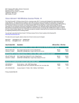
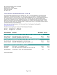
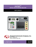
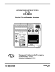

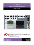
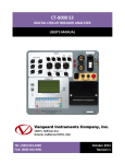


![DTF-7500S 機能追加のお知らせ [PDF:76.1KB]](http://vs1.manualzilla.com/store/data/006673767_2-d94886004dd4730bddb55701cf046dda-150x150.png)