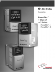
1
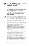
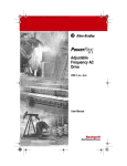
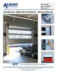
Quick Start
PowerFlex 4 Adjustable
Frequency AC Drive
FRN 4.xx
This Quick Start guide summarizes the basic steps needed to install,
start-up and program the PowerFlex 4 Adjustable Frequency AC Drive.
The information provided Does Not replace the User Manual and is
intended for qualified drive service personnel only.
For detailed PowerFlex 4 information including EMC instructions,
application considerations and related precautions refer to the
PowerFlex 4 User Manual, Publication 22A-UM001… on the CD
supplied with the drive or at www.rockwellautomation.com/literature.
General Precautions
!
ATTENTION: The drive contains high voltage capacitors which take
time to discharge after removal of mains supply. Before working on
drive, ensure isolation of mains supply from line inputs [R, S, T (L1,
L2, L3)]. Wait three minutes for capacitors to discharge to safe voltage
levels. Failure to do so may result in personal injury or death.
Darkened display LEDs is not an indication that capacitors have
discharged to safe voltage levels.
!
!
!
!
ATTENTION: Equipment damage and/or personal injury may result
if parameter A092 [Auto Rstrt Tries] or A094 [Start At PowerUp] is
used in an inappropriate application. Do not use this function without
considering applicable local, national and international codes,
standards, regulations or industry guidelines.
ATTENTION: Only qualified personnel familiar with adjustable
frequency AC drives and associated machinery should plan or
implement the installation, start-up and subsequent maintenance of the
system. Failure to comply may result in personal injury and/or
equipment damage.
ATTENTION: This drive contains ESD (Electrostatic Discharge)
sensitive parts and assemblies. Static control precautions are required
when installing, testing, servicing or repairing this assembly.
Component damage may result if ESD control procedures are not
followed. If you are not familiar with static control procedures,
reference A-B publication 8000-4.5.2, “Guarding Against Electrostatic
Damage” or any other applicable ESD protection handbook.
ATTENTION: An incorrectly applied or installed drive can result in
component damage or a reduction in product life. Wiring or application
errors, such as, undersizing the motor, incorrect or inadequate AC
supply, or excessive ambient temperatures may result in malfunction of
the system.
English-2
Mounting Considerations
•
Mount the drive upright on a flat, vertical and level surface.
Min. Panel Thickness
1.9 mm (0.0747 in.)
•
•
•
Screw Size
M4 (#8-32)
Screw Torque
DIN Rail
1.56-1.96 N-m (14-17 lb.-in.) 35 mm
Protect the cooling fan by avoiding dust or metallic particles.
Do not expose to a corrosive atmosphere.
Protect from moisture and direct sunlight.
Minimum Mounting Clearances
See page 12 for mounting dimensions.
25 mm
(1.0 in.)
120 mm
(4.7 in.)
120 mm
(4.7 in.)
Mounting Option A
No clearance required
between drives.
Mounting Option B
120 mm
(4.7 in.)
120 mm
(4.7 in.)
Ambient Operating Temperatures
Ambient Temperature
Minimum
Maximum
-10°C (14°F)
(1)
Enclosure Rating
Minimum Mounting
Clearances
IP 20/Open Type
Use Mounting Option A
IP 30/NEMA 1/UL Type 1(1) Use Mounting Option B
50°C (122°F) IP 20/Open Type
Use Mounting Option B
40°C (104°F)
Rating requires installation of the PowerFlex 4 IP 30/NEMA 1/UL Type 1 option kit.
General Grounding Requirements
Important: The MOV to ground jumper must be
removed if the drive is installed on an ungrounded or
resistive grounded distribution system.
Tighten screw after jumper removal.
Jumper
Location
R/L1
S/L2
T/L3
U/T1
V/T2
W/T3
SHLD
CE Conformity
Refer to the PowerFlex 4 User Manual on the CD supplied with the drive
for details on how to comply with the Low Voltage (LV) and
Electromagnetic Compatibility (EMC) Directives.
English-3
Specifications, Fuses and Circuit Breakers
Drive Ratings
Voltage
kW (HP) Amps Range
kVA Amps Fuses
100 - 120V AC (±10%) – 1-Phase Input, 0 - 230V 3-Phase Output
140M Motor
Protectors(2)
Power
Dissipation
IP20 Open
Contactors Watts
22A-V1P5N104
22A-V2P3N104
22A-V4P5N104
22A-V6P0N104
140M-C2E-C10
140M-C2E-C16
140M-D8E-C20
140M-D8E-C25
100-C09
100-C12
100-C23
100-C37
32
40
55
80
140M-C2E-B40
140M-C2E-B63
140M-C2E-C16
140M-C2E-C16
140M-D8E-C25
100-C09
100-C09
100-C12
100-C16
100-C23
32
40
55
85
125
140M-C2E-B63
140M-C2E-B63
140M-C2E-C16
140M-D8E-C20
100-C09
100-C09
100-C12
100-C23
32
40
55
85
140M-C2E-B25
140M-C2E-B40
140M-C2E-C10
140M-C2E-C16
140M-C2E-C16
140M-F8E-C25
100-C09
100-C09
100-C09
100-C12
100-C16
100-C23
32
40
55
85
125
180
140M-C2E-B25
140M-C2E-B40
140M-C2E-B63
140M-C2E-C10
140M-C2E-C16
100-C09
100-C09
100-C09
100-C09
100-C16
35
50
70
100
150
Catalog
Number
Output Ratings
0.2 (0.25)
0.4 (0.5)
0.75 (1.0)
1.1 (1.5)
1.5
2.3
4.5
6.0
Input Ratings
90-126
90-126
90-126
90-126
0.75
1.15
2.25
3.0
Branch Circuit Protection
6.0
9.0
18.0
24.0
10
15
30
40
200 - 240V AC (±10%) – 1-Phase(1) Input, 0 - 230V 3-Phase Output, NO BRAKE
22A-A1P4N103
22A-A2P1N103
22A-A3P6N103
22A-A6P8N103
22A-A9P6N103
0.2 (0.25)
0.4 (0.5)
0.75 (1.0)
1.5 (2.0)
2.2 (3.0)
1.4
2.1
3.6
6.8
9.6
180-265
180-265
180-265
180-265
180-265
0.7 3.2
1.05 5.3
1.8 9.2
3.4 14.2
4.8 19.6
6
10
15
25
30
200 - 240V AC (±10%) – 1-Phase(1) Input, 0 - 230V 3-Phase Output
22A-A1P5N104
22A-A2P3N104
22A-A4P5N104
22A-A8P0N104
0.2 (0.25)
0.4 (0.5)
0.75 (1.0)
1.5 (2.0)
1.5
2.3
4.5
8.0
180-265
180-265
180-265
180-265
0.75 5.0
1.15 6.0
2.25 10.0
4.0 18.0
10
10
15
30
200 - 240V AC (±10%) – 3-Phase Input, 0 - 230V 3-Phase Output
22A-B1P5N104
22A-B2P3N104
22A-B4P5N104
22A-B8P0N104
22A-B012N104
22A-B017N104
0.2 (0.25)
0.4 (0.5)
0.75 (1.0)
1.5 (2.0)
2.2 (3.0)
3.7 (5.0)
1.5
2.3
4.5
8.0
12.0
17.5
180-265
180-265
180-265
180-265
180-265
180-265
0.75
1.15
2.25
4.0
5.5
8.6
1.8
2.5
5.2
9.5
15.5
21.0
3
6
10
15
25
30
380 - 480V AC (±10%) – 3-Phase Input, 0 - 460V 3-Phase Output
22A-D1P4N104
22A-D2P3N104
22A-D4P0N104
22A-D6P0N104
22A-D8P7N104
0.4 (0.5)
0.75 (1.0)
1.5 (2.0)
2.2 (3.0)
3.7 (5.0)
1.4
2.3
4.0
6.0
8.7
340-528
340-528
340-528
340-528
340-528
1.4
2.3
4.0
5.9
8.6
1.8
3.2
5.7
7.5
9.0
3
6
10
15
15
Approvals
Input/Output Ratings
Output Frequency: 0-240 Hz (Programmable)
Efficiency: 97.5% (Typical)
C
UL
®
UL508C
CSA 22.2
US No. 14
EMC Directive 89/336/EEC, LV Dir. 73/23/EEC
LV: EN 50178
EMC: EN 61800-3
Digital Control Inputs (Input Current = 6mA)
Analog Control Inputs
SRC (Source) Mode:
18-24V = ON
0-6V = OFF
4-20mA Analog: 250 ohm input impedance
0-10V DC Analog: 100k ohm input impedance
External Pot: 1-10k ohms, 2 Watt minimum
SNK (Sink) Mode:
0-6V = ON
18-24V = OFF
Control Output (Programmable Output, form C relay)
Resistive Rating: 3.0A at 30V DC, 125V AC and 240V AC
Inductive Rating: 0.5A at 30V DC, 125V AC, and 240V AC
Recommended Fuses and Circuit Breakers
Fuse: UL Class J, CC, T or Type BS88; 600V (550V) or equivalent. Circuit Breakers: HMCP or Bulletin 140U or equivalent.
Protective Features
Motor Protection: I2t overload protection - 150% for 60 Secs, 200% for 3 Secs (Provides Class 10 protection)
Overcurrent: 200% hardware limit, 300% instantaneous fault
Over Voltage:
100-120V AC Input – Trip occurs at 405V DC bus voltage (equivalent to 150V AC incoming line)
200-240V AC Input – Trip occurs at 405V DC bus voltage (equivalent to 290V AC incoming line)
380-460V AC Input – Trip occurs at 810V DC bus voltage (equivalent to 575V AC incoming line)
Under Voltage: 100-120V AC Input – Trip occurs at 210V DC bus voltage (equivalent to 75V AC incoming line)
200-240V AC Input – Trip occurs at 210V DC bus voltage (equivalent to 150V AC incoming line)
380-480V AC Input – Trip occurs at 390V DC bus voltage (equivalent to 275V AC incoming line)
Control Ride Through: Minimum ride through is 0.5 Secs - typical value 2 Secs
Faultless Power Ride Through: 100 milliseconds
Dynamic Braking
Internal brake IGBT included with all ratings except No Brake versions. Refer to Appendix B of the PowerFlex 4 User Manual on
CD for ordering information.
(1)
(2)
200-240V AC - 1-Phase drives are also available with an integral EMC filter. Catalog suffix changes from N103 to N113
and N104 to N114.
Refer to the Bulletin 140M Motor Protectors Selection Guide, publication 140M-SG001… to determine the frame and
breaking capacity required for your application.
English-4
Power Wiring
Power Wire Rating
Recommended Copper Wire
Unshielded 600V, 75°C (167°F) THHN/THWN
15 Mils insulated, dry location
Shielded 600V, 75°C or 90°C (167°F or 194°F) RHH/RHW-2
Belden 29501-29507 or equivalent
Shielded Tray rated 600V, 75°C or 90°C (167°F or 194°F) RHH/RHW-2
Shawflex 2ACD/3ACD or equivalent
Power Terminal Block (A Frame Shown)
Terminal
R/L1 S/L2 T/L3 U/T1 V/T2 W/T3
Description
R/L1, S/L2
1-Phase Input
R/L1, S/L2, T/L3
3-Phase Input
U/T1
To Motor U/T1
V/T2
To Motor V/T2
BR+ BR-
Switch any two motor leads to
change forward direction.
=
W/T3
To Motor W/T3
BR+, BR-
Dynamic Brake Resistor Connection [0.75 kW (1 HP) ratings and higher]
Safety Ground - PE
Power Terminal Block Specifications
Frame
Maximum Wire Size (1)
Minimum Wire Size (1)
A
3.3 mm2 (12 AWG)
0.8 mm2 (18 AWG)
B
5.3 mm2 (10 AWG)
1.3 mm2 (16 AWG)
(1)
Torque
1.7-2.2 N-m (16-19 lb.-in.)
Maximum/minimum sizes that the terminal block will accept - these are not recommendations.
Input Power Conditions
Input Power Condition
Corrective Action
Low Line Impedance (less than 1% line reactance)
•
•
Install Line Reactor(2)
or Isolation Transformer
•
•
Remove MOV jumper to ground.
or Install Isolation Transformer with
grounded secondary if necessary.
Greater than 120 kVA supply transformer
Line has power factor correction capacitors
Line has frequent power interruptions
Line has intermittent noise spikes in excess of 6000V (lightning)
Phase to ground voltage exceeds 125% of normal line to line voltage
Ungrounded Distribution System
(2)
Refer to Appendix B of the PowerFlex 4 User Manual on CD for accessory ordering information.
I/O Wiring Recommendations(3)
Wire Type(s)
Description
Belden 8760/9460
(or equiv.)
0.8 mm2 (18AWG), twisted pair, 100% shield with
drain.
Minimum Insulation Rating
300V
60 degrees C
Belden 8770
0.8 mm2 (18AWG), 3 conductor, shielded for remote (140 degrees F)
(or equiv.)
pot only.
(3)
If the wires are short and contained within a cabinet which has no sensitive circuits, the use of shielded wire may not be
necessary, but is always recommended.
I/O Terminal Block Specifications
Maximum Wire Size (4)
Minimum Wire Size (4)
Torque
1.3 mm2 (16 AWG)
0.13 mm2 (26 AWG)
0.5-0.8 N-m (4.4-7 lb.-in.)
(4)
Maximum / minimum that the terminal block will accept - these are not recommendations.
Refer to the PowerFlex 4 User Manual on CD for maximum power and
control cable length recommendations
English-5
Control Terminal Block
(1)
Important: I/O Terminal 01 is
always a coast to stop input except
when P036 [Start Source] is set to
“3-Wire” control. In three wire
control, I/O Terminal 01 is controlled
by P037 [Stop Mode]. All other stop
sources are controlled by P037
[Stop Mode].
P036
[Start Source]
Stop
Keypad
Per P037
Coast
3-Wire
Per P037
Per P037
2-Wire
Per P037
Coast
RS485 Port
Per P037
Coast
01
Important: The drive is shipped with
a jumper installed between I/O
Terminals 01 and 11. Remove this
jumper when using I/O Terminal 01
as a stop or enable input.
02
03
SNK
SRC
04
05
(2) Two wire control shown. For three
wire control use a momentary input
on I/O Terminal 02 to
command a start. Use a maintained
input
for I/O Terminal 03 to
change direction.
Relay N.O.
Relay Common
Relay N.C.
Refer to the PowerFlex 4
User Manual on CD for
detailed I/O wiring examples.
I/O Terminal 01
Stop
06
+24V
+10V
11
12
13
R1
14
R2
15
R3
16
Stop
Typical
Typical
SRC Wiring SNK Wiring
(1)
Start/Run FWD
(2)
Direction/Run REV
Digital Common
Digital Input 1
Digital Input 2
+24V DC
+10V DC
0-10V In
Analog Common
4-20mA In
RS485 Shield
Potentiometer
must be
1-10k ohm
2 Watt Min.
01 02 03 04 05 06
R1 R2 R3
30V DC 125V AC 240V AC
Resistive
3.0A
3.0A
3.0A
Inductive
0.5A
0.5A
0.5A
SNK
SRC
11
12 13 14 15 16
(1)
RS485
(DSI)
8 1
No. Signal
Default
Description
Param.
R1
R2
R3
Fault
–
Fault
Normally open contact for output relay.
Common for output relay.
Normally closed contact for output relay.
A055
Source (SRC)
Inputs can be wired as Sink (SNK) or Source (SRC) via DIP Switch setting.
Coast
The factory installed jumper or a normally closed input
must be present for the drive to start.
Relay N.O.
Relay Common
Relay N.C.
Sink/Source DIP Switch
01
Stop(1)
02
Start/Run FWD
Not Active
03
Direction/Run REV
Not Active
04
Digital Common
–
05
06
Digital Input 1
Digital Input 2
Preset Freq
Preset Freq
11
+24V DC
–
12
+10V DC
–
13
0-10V In(3)
Not Active
14
Analog Common
–
15
4-20mA In(3)
Not Active
16
RS485 (DSI) Shield
–
(3)
A055
P036(1)
P036, P037
Command comes from the integral keypad by default. To
disable reverse operation, see A095 [Reverse Disable]. P036, P037,
A095
For digital inputs. Electronically isolated with digital inputs
from analog I/O.
Program with A051 [Digital In1 Sel].
A051
Program with A052 [Digital In2 Sel].
A052
Drive supplied power for digital inputs.
Maximum output current is 100mA.
Drive supplied power for 0-10V external potentiometer.
P038
Maximum output current is 15mA.
For external 0-10V input supply
P038
(input impedance = 100k ohm) or potentiometer wiper.
For 0-10V In or 4-20mA In. Electronically isolated with
analog inputs from digital I/O.
For external 4-20mA input supply
P038
(input impedance = 250 ohm).
Terminal should be connected to safety ground - PE when
using the RS485 (DSI) communications port.
Only one analog frequency source may be connected at a time. If more than one reference is connected at the same
time, an undetermined frequency reference will result.
English-6
Prepare For Drive Start-Up
!
ATTENTION: Power must be applied to the drive to perform the
following start-up procedures. Some of the voltages present are at
incoming line potential. To avoid electric shock hazard or damage to
equipment, only qualified service personnel should perform the
following procedure. Thoroughly read and understand the procedure
before beginning. If an event does not occur while performing this
procedure, Do Not Proceed. Remove All Power including user
supplied control voltages. User supplied voltages may exist even when
main AC power is not applied to the drive. Correct the malfunction
before continuing.
Before Applying Power to the Drive
❏ 1. Confirm that all inputs are connected to the correct terminals and are
secure.
❏ 2. Verify that AC line power at the disconnect device is within the rated
value of the drive.
❏ 3. Verify that any digital control power is 24 volts.
❏ 4. Verify that the Sink (SNK)/Source (SRC) Setup DIP Switch is set to
match your control wiring scheme. See page 5 for location.
Important: The default control scheme is Source (SRC). The Stop
terminal is jumpered (I/O Terminals 01 and 11) to allow
starting from the keypad. If the control scheme is changed
to Sink (SNK), the jumper must be removed from I/O
Terminals 01 and 11 and installed between I/O Terminals
01 and 04.
❏ 5. Verify that the Stop input is present or the drive will not start.
Important: If I/O Terminal 01 is used as a stop input, the jumper
between I/O Terminals 01 and 11 must be removed.
Applying Power to the Drive
❏ 6. Apply AC power and control voltages to the drive.
❏ 7. Familiarize yourself with the integral keypad features (see next page)
before setting any Program Group parameters.
Start, Stop, Direction and Speed Control
Factory default parameter values allow the drive to be controlled from
the integral keypad. No programming is required to start, stop, change
direction and control speed directly from the integral keypad.
Important: To disable reverse operation, see A095 [Reverse Disable].
If a fault appears on power up, refer to page 11 for an explanation of the
fault code. For complete troubleshooting information, refer to the
PowerFlex 4 User Manual on the CD supplied with the drive.
English-7
Integral Keypad
➋
➊
➌
RUN
FWD
REV
PROGRAM
➍
➎
Description
Display Group (View Only)
Consists of commonly viewed drive operating
conditions.
FAULT
➑
➐
➏
Menu
VOLTS
AMPS
HERTZ
➒
Basic Program Group
Consists of most commonly used
programmable functions.
Advanced Program Group
Consists of remaining programmable functions.
Fault Designator
Consists of list of codes for specific fault
conditions. Displayed only when fault is present.
No. LED
➊ Run/Direction
Status
LED State
Steady Red
Flashing Red
➋
Alphanumeric
Display
Steady Red
Flashing Red
➌
➍
➎
➏
➐
Displayed Units
Steady Red
Description
Indicates drive is running and commanded motor direction.
Drive has been commanded to change direction. Indicates
actual motor direction while decelerating to zero.
Indicates parameter number, parameter value, or fault code.
Single digit flashing indicates that digit can be edited.
All digits flashing indicates a fault condition.
Indicates the units of the parameter value being displayed.
Program Status
Steady Red
Indicates parameter value can be changed.
Fault Status
Flashing Red
Indicates drive is faulted.
Pot Status
Steady Green
Indicates potentiometer on Integral Keypad is active.
Start Key Status Steady Green
No. Key
➑
Name
Escape
Select
Up Arrow
Down Arrow
Enter
➒
Potentiometer
Start
Reverse
Stop
Indicates Start key on Integral Keypad is active.
The Reverse key is also active unless disabled by A095
[Reverse Disable].
Description
Back one step in programming menu.
Cancel a change to a parameter value and exit Program
Mode.
Advance one step in programming menu.
Select a digit when viewing parameter value.
Scroll through groups and parameters.
Increase/decrease the value of a flashing digit.
Advance one step in programming menu.
Save a change to a parameter value.
Used to control speed of drive. Default is active.
Controlled by parameter P038.
Used to start the drive. Default is active.
Controlled by parameter P036.
Used to reverse direction of the drive. Default is active.
Controlled by parameters P036 and A095.
Used to stop the drive or clear a fault.
This key is always active.
Controlled by parameter P037.
English-8
Viewing and Editing Parameters
The last user-selected Display Group parameter is saved when power is removed and is
displayed by default when power is reapplied.
The following is an example of basic integral keypad and display functions. This example
provides basic navigation instructions and illustrates how to program the first Program
Group parameter.
Step
Key(s)
1. When power is applied, the last user-selected
Display Group parameter number is briefly
displayed with flashing characters. The display
then defaults to that parameter’s current value.
(Example shows the value of d001 [Output
Freq] with the drive stopped.)
Example Displays
VOLTS
AMPS
HERTZ
PROGRAM
2. Press Esc once to display the Display Group
parameter number shown on power-up. The
parameter number will flash.
FAULT
VOLTS
AMPS
HERTZ
PROGRAM
FAULT
3. Press Esc again to enter the group menu. The
group menu letter will flash.
VOLTS
AMPS
HERTZ
4. Press the Up Arrow or Down Arrow to scroll
through the group menu (d, P and A).
or
5. Press Enter or Sel to enter a group. The right
digit of the last viewed parameter in that group
will flash.
or
6. Press the Up Arrow or Down Arrow to scroll
through the parameters that are in the group.
or
7. Press Enter or Sel to view the value of a
parameter. If you do not want to edit the value,
press Esc to return to the parameter number.
or
8. Press Enter or Sel to enter program mode to
edit the parameter value. The right digit will
flash and the Program LED will illuminate if the
parameter can be edited.
or
9. Press the Up Arrow or Down Arrow to change
the parameter value. If desired, press Sel to
move from digit to digit or bit to bit. The digit or
bit that you can change will flash.
or
PROGRAM
FAULT
VOLTS
AMPS
HERTZ
PROGRAM
FAULT
VOLTS
AMPS
HERTZ
PROGRAM
FAULT
VOLTS
AMPS
HERTZ
PROGRAM
FAULT
10. Press Esc to cancel a change. The digit will
stop flashing, the previous value is restored and
the Program LED will turn off.
Or
Press Enter to save a change. The digit will stop
flashing and the Program LED will turn off.
VOLTS
AMPS
HERTZ
PROGRAM
11. Press Esc to return to the parameter list.
Continue to press Esc to back out of the
programming menu.
If pressing Esc does not change the display,
then d001 [Output Frequency] is displayed.
Press Enter or Sel to enter the group menu.
FAULT
VOLTS
AMPS
HERTZ
PROGRAM
FAULT
English-9
See the PowerFlex 4 User Manual on CD for more information on parameters.
Display Group Parameters
No.
Parameter
Min/Max
Display/Options
d001
d002
d003
d004
d005
d006
[Output Freq]
[Commanded Freq]
[Output Current]
[Output Voltage]
[DC Bus Voltage]
[Drive Status]
0.0/[Maximum Freq]
0.0/[Maximum Freq]
0.00/(Drive Amps × 2)
0/Drive Rated Volts
Based on Drive Rating
0/1 (1 = Condition True)
0.1 Hz
0.1 Hz
0.01 Amps
1 VAC
1 VDC
Bit 3
Decelerating
F1
d007- [Fault x Code]
d009
d010 [Process Display]
d012 [Control Source]
F2/F122
0.00/9999
0/9
d013 [Contrl In Status]
0/1 (1 = Input Present)
d014 [Dig In Status]
0/1 (1 = Input Present)
d015 [Comm Status]
0/1 (1 = Condition True)
d016
d017
d018
d019
d020
d021
d024
1.00/99.99
1001/9999
0/9999 Hrs
0/FFFF
0.0/100.0%
0.0/100.0%
0/120 degC
[Control SW Ver]
[Drive Type]
[Elapsed Run Time]
[Testpoint Data]
[Analog In 0-10V]
[Analog In 4-20mA]
[Drive Temp]
Bit 2
Accelerating
0.01 – 1
Digit 1 = Speed Command
(See P038; 9 = “Jog Freq”)
Bit 3
Bit 2
Reserved
Stop Input
Bit 3
Bit 2
Reserved
Reserved
Bit 3
Bit 2
Fault Occurred RS485 Option
0.01
1
1 = 10 Hrs
1 Hex
0.1%
0.1%
1 degC
Bit 1
Forward
Bit 0
Running
Digit 0 = Start Command
(See P036; 9 = “Jog”)
Bit 1
Bit 0
Dir/Run REV
Start/Run FWD
Bit 1
Bit 0
Digital In2 Sel Digital In1 Sel
Bit 1
Bit 0
Transmitting
Receiving
Smart Start-Up with Basic Program Group Parameters
= Stop drive before changing this parameter.
No.
Parameter
Min/Max
Display/Options
Default
P031 [Motor NP Volts]
20/Drive Rated Volts
1 VAC
Based on Drive Rating
Set to the motor nameplate rated volts.
P032 [Motor NP Hertz]
10/240 Hz
1 Hz
60 Hz
Set to the motor nameplate rated frequency.
P033 [Motor OL Current] 0.0/(Drive Rated Amps×2) 0.1 Amps
Based on Drive Rating
Set to the maximum allowable motor current.
P034 [Minimum Freq]
0.0/240.0 Hz
0.1 Hz
0.0 Hz
Sets the lowest frequency the drive will output continuously.
P035 [Maximum Freq]
0/240 Hz
1 Hz
60 Hz
Sets the highest frequency the drive will output.
P036 [Start Source]
0/5
0 = “Keypad”(1)
3 = “2-W Lvl Sens” 0
4 = “2-W Hi Speed”
Sets the control scheme used to start the drive. 1 = “3-Wire”
2 = “2-Wire”
5 = “Comm Port”
(1) When active, the Reverse key is also active unless disabled by A095 [Reverse Disable].
(1)
P037 [Stop Mode]
0/7
0 = “Ramp, CF”
4 = “Ramp”
0
(1)
Active stop mode for all stop sources [e.g. keypad, 1 = “Coast, CF” (1) 5 = “Coast”
2
=
“DC
Brake,
CF”
6
=
“DC
Brake”
run forward (I/O Terminal 02), run reverse (I/O
(1)
Terminal 03), RS485 port] except as noted below. 3 = “DCBrkAuto,CF” 7 = “DC BrakeAuto”
P038
P039
P040
P041
P043
Important: I/O Terminal 01 is always a coast to stop input except when P036 [Start Source] is set for “3-Wire” control.
When in three wire control, I/O Terminal 01 is controlled by P037 [Stop Mode].
(1) Stop input also clears active fault.
[Speed Reference]
0/5
0 = “Drive Pot”
3 = “4-20mA Input” 0
4 = “Preset Freq”
Sets the source of the speed reference to the drive. 1 = “InternalFreq”
2 = “0-10V Input”
5 = “Comm Port”
Important: When A051 or A052 [Digital Inx Sel] is set to option 2, 4, 5, 6, 13 or 14, and the digital input is active, A051
or A052 will override the speed reference commanded by this parameter. Refer to Chapter 1 of the PowerFlex 4 User
Manual on CD for details.
[Accel Time 1]
0.0/600.0 Secs
0.1 Secs
10.0 Secs
Sets the rate of accel for all speed increases.
[Decel Time 1]
0.1/600.0 Secs
0.1 Secs
10.0 Secs
Sets the rate of decel for all speed decreases.
[Reset To Defalts]
0/1
0 = “Idle State”
0
1 = “Reset Defaults”
Resets all parameter values to factory defaults.
[Motor OL Ret]
0/1
0 = “Disabled”
1 = “Enabled”
0
Enables/disables the Motor Overload Retention function.
English-10
See the PowerFlex 4 User Manual on CD for more information on parameters.
Advanced Group Parameters
No.
Min/Max
Display/Options
A051 [Digital In1 Sel]
I/O Terminal 05
A052 [Digital In2 Sel]
I/O Terminal 06
0/26
A055 [Relay Out Sel]
0/21
0 = “Not Used”
1 = “Acc 2 & Dec 2”
2 = “Jog”
3 = “Aux Fault”
4 = “Preset Freq”
5 = “Local”
6 = “Comm Port”
7 = “Clear Fault”
0 = “Ready/Fault”
1 = “At Frequency”
2 = “MotorRunning”
3 = “Reverse”
4 = “Motor Overld”
5 = “Ramp Reg”
A056
A067
A068
A069
A070
A071
A072
A073
Parameter
Default
8 = “RampStop,CF”
9 = “CoastStop,CF”
10 = “DCInjStop,CF”
11 = “Jog Forward”
12 = “Jog Reverse”
13 = “10V In Ctrl”
14 = “20mA In Ctrl”
26 = “Anlg Invert”
6 = “Above Freq”
7 = “Above Cur”
8 = “Above DCVolt”
9 = “Retries Exst”
10 = “Above Anlg V”
20 = “ParamControl”
21 = “NonRec Fault”
[Relay Out Level]
0.0/9999
0.1
[Accel Time 2]
0.0/600.0 Secs
0.1 Secs
[Decel Time 2]
0.1/600.0 Secs
0.1 Secs
[Internal Freq]
0.0/240.0 Hz
0.1 Hz
(1)
0.0/240.0 Hz
0.1 Hz
[Preset Freq 0]
[Preset Freq 1]
[Preset Freq 2]
[Preset Freq 3]
(1) To activate [Preset Freq 0] set P038 [Speed Reference] to option 4.
4
0
0.0
20.0 Secs
20.0 Secs
60.0 Hz
0.0 Hz
5.0 Hz
10.0 Hz
20.0 Hz
(2)
Input State of Digital In 1
Input State of Digital In 2
Frequency Source
Accel / Decel Parameter Used
(I/O Terminal 05)
(I/O Terminal 06)
0
0
[Preset Freq 0]
[Accel Time 1] / [Decel Time 1]
1
0
[Preset Freq 1]
[Accel Time 1] / [Decel Time 1]
0
1
[Preset Freq 2]
[Accel Time 2] / [Decel Time 2]
1
1
[Preset Freq 3]
[Accel Time 2] / [Decel Time 2]
(2)
When a Digital Input is set to “Accel 2 & Decel 2”, and the input is active, that input overrides the settings in this table.
A078
A079
A080
A081
A082
[Jog Frequency]
[Jog Accel/Decel]
[DC Brake Time]
[DC Brake Level]
[DB Resistor Sel]
A083 [S Curve %]
A084 [Start Boost]
A088 [Maximum Voltage]
A089 [Current Limit]
A090 [Motor OL Select]
A091
A092
A093
A094
[PWM Frequency]
[Auto Rstrt Tries]
[Auto Rstrt Delay]
[Start At PowerUp]
0.0/[Maximum Freq]
0.1/600.0 Secs
0.0/90.0 Secs
0.0/(Drive Amps × 1.8)
0/99
0.1 Hz
0.1 Secs
0.1 Secs
0.1 Amps
0 = Disabled
1 = Normal RA Res
2 = NoProtection
3-99 = % of Duty Cycle
10.0 Hz
10.0 Secs
0.0 Secs
Amps × 0.05
0
0/100%
1/14
1%
0% (Disabled)
Settings in % of base voltage.
8
7 (5 HP Drives)
Variable Torque Constant Torque
1 = “30.0, VT”
5 = “0.0, no IR”
10 = “10.0, CT”
2 = “35.0, VT”
6 = “0.0”
11 = “12.5, CT”
3 = “40.0, VT”
7 = “2.5, CT”
12 = “15.0, CT”
4 = “45.0, VT”
8 = “5.0, CT”
13 = “17.5, CT”
9 = “7.5, CT”
14 = “20.0, CT”
20/Rated Volts
1 VAC
Rated Volts
0.1/(Drive Amps × 1.8) 0.1 Amps
Amps × 1.5
0/2
0 = “No Derate”
1 = “Min Derate”
0
2 = “Max Derate”
2.0/16.0 kHz
0.1 kHz
4.0 kHz
0/9
1
0
0.0/300.0 Secs
0.1 Secs
1.0 Secs
0/1
0 = “Disabled”
1 = “Enabled”
0
A095 [Reverse Disable]
0/1
0 = “Rev Enabled”
1 = “Rev Disabled”
0
A096 [Flying Start En]
A097 [Compensation]
0/1
0/3
1 = “Enabled”
2 = “Mechanical”
3 = “Both”
0
1
A098 [SW Current Trip]
A099 [Process Factor]
A100 [Fault Clear]
0.0/(Drive Amps × 2)
0.1/999.9
0/2
0 = “Disabled”
0 = “Disabled”
1 = “Electrical”
0.1 Amps
0.1
0 = “Ready/Idle”
A101 [Program Lock]
A102 [Testpoint Sel]
0/1
0/FFFF
0 = “Unlocked”
1 Hex
1 = “Reset Fault”
2 = “Clear Buffer”
1 = “Locked”
0.0 (Disabled)
30.0
0
0
400
English-11
See the PowerFlex 4 User Manual on CD for more information on parameters.
No.
Parameter
Min/Max
A103 [Comm Data Rate](3) 0/5
Display/Options
Default
A106 [Comm Loss Time]
A107 [Comm Format](3)
0.1/60.0
0/5
A110 [Anlg In 0-10V Lo]
0.0/100.0%
0 = “1200”
1 = “2400”
2 = “4800”
1
0 = “Fault”
1 = “Coast to Stop”
0.1
0 = “RTU 8-N-1”
1 = “RTU 8-E-1”
2 = “RTU 8-O-1”
0.1%
A111 [Anlg In 0-10V Hi]
0.0/100.0%
0.1%
100.0%
A112 [Anlg In4-20mA Lo]
0.0/100.0%
0.1%
0.0%
A113 [Anlg In4-20mA Hi]
0.0/100.0%
0.1%
100.0%
A104 [Comm Node Addr](3) 1/247
A105 [Comm Loss Action] 0/3
3 = “9600”
4 = “19.2K”
5 = “38.4K”
2 = “Stop”
3 = “Continu Last”
3 = “RTU 8-N-2”
4 = “RTU 8-E-2”
5 = “RTU 8-O-2”
A114 [Slip Hertz @ FLA] 0.0/10.0 Hz
0.1 Hz
A115 [Process Time Lo]
0.00/99.99
0.01
A116 [Process Time Hi]
0.00/99.99
0.01
(3) Power to drive must be cycled before any changes will affect drive operation.
3
100
0
5.0
0
0.0%
2.0 Hz
0.00
0.00
Fault Codes
To clear a fault, press the Stop key, cycle power or set A100 [Fault Clear] to 1 or 2.
No.
Fault
Description
F2
F3
F4
F5
Auxiliary Input(1)
Power Loss
UnderVoltage(1)
OverVoltage(1)
F6
Motor Stalled(1)
F7
Motor Overload(1)
F8
Heatsink OvrTmp(1)
F12
HW OverCurrent(1)
F13
F33
F38
F39
F40
F41
F42
F43
F48
Ground Fault
Auto Rstrt Tries
Phase U to Gnd
Phase V to Gnd
Phase W to Gnd
Phase UV Short
Phase UW Short
Phase VW Short
Params Defaulted
Check remote wiring.
Monitor the incoming AC line for low voltage or line power interruption.
Monitor the incoming AC line for low voltage or line power interruption.
Monitor the AC line for high line voltage or transient conditions. Bus overvoltage can also be
caused by motor regeneration. Extend the decel time or install dynamic brake option.
Increase [Accel Time x] or reduce load so drive output current does not exceed the current set
by parameter A089 [Current Limit].
An excessive motor load exists. Reduce load so drive output current does not exceed the
current set by parameter P033 [Motor OL Current].
Check for blocked or dirty heat sink fins. Verify that ambient temperature has not exceeded 40°C
(104°F) for IP 30/NEMA 1/UL Type 1 installations or 50°C (122°F) for Open type installations.
Check fan.
Check programming. Check for excess load, improper DC boost setting, DC brake volts set too
high or other causes of excess current.
Check the motor and external wiring to the drive output terminals for a grounded condition.
Correct the cause of the fault and manually clear.
Check the wiring between the drive and motor. Check motor for grounded phase.
Replace drive if fault cannot be cleared.
Check the motor and drive output terminal wiring for a shorted condition.
Replace drive if fault cannot be cleared.
The drive was commanded to write default values to EEPROM. Clear the fault or cycle power to
the drive. Program the drive parameters as needed.
F63 SW OverCurrent(1) Check load requirements and A098 [SW Current Trip] setting.
F64 Drive Overload
Reduce load or extend Accel Time.
F70 Power Unit
Cycle power. Replace drive if fault cannot be cleared.
F71 Net Loss
The communication network has faulted.
F81 Comm Loss
If adapter was not intentionally disconnected, check wiring to the port. Replace wiring, port
expander, adapters or complete drive as required. Check connection. An adapter was
intentionally disconnected. Turn off using A105 [Comm Loss Action].
F100 Parameter Checksum Restore factory defaults.
F122 I/O Board Fail
Cycle power. Replace drive if fault cannot be cleared.
(1)
Auto-Reset/Run type fault. Configure with parameters A092 and A093.
English-12
Drive Dimensions
Frame
PowerFlex 4 Panel Mount Drives – Ratings are in kW and (HP)
120V AC – 1-Phase
240V AC – 1-Phase
240V AC – 1-Phase 240V AC – 3-Phase 480V AC – 3-Phase
No Brake
A
0.2 (0.25)
0.37(0.5)
0.2 (0.25)
0.37 (0.5)
0.75 (1.0)
0.2 (0.25)
0.37 (0.5)
0.75 (1.0)
B
0.75(1.0)
1.1 (1.5)
1.5 (2.0)
2.2 (3.0)
1.5 (2.0)
0.2 (0.25)
0.37 (0.5)
0.75 (1.0)
1.5 (2.0)
2.2 (3.0)
3.7 (5.0)
0.37 (0.5)
0.75 (1.0)
1.5 (2.0)
2.2 (3.0)
3.7 (5.0)
PowerFlex 4 Panel Mount Drives (1)– Dimensions are in millimeters and (inches).
Weights are in kilograms and (pounds).
A
D
C
F
GEB
5.5 (0.22)
Frame
A
B (2)
C
D
E (3)
F
G
Shipping
Weight
A
B
80 (3.15)
100 (3.94)
185 (7.28)
213 (8.39)
136 (5.35)
136 (5.35)
67 (2.64)
87 (3.43)
152 (5.98)
180 (7.09)
59.3 (2.33)
87.4 (3.44)
140 (5.51)
168 (6.61)
1.4 (3.1)
2.2 (4.9)
(1) Flange Mount drives are also available. Refer to the PowerFlex 4 User Manual on CD for information.
(2) Overall height of drive with IP 30/NEMA 1/UL Type 1 option kit installed.
(3) Overall height of standard IP 20/Open Type drive.
IP 30/NEMA 1/UL Type 1 Option Kit – Dimensions are in millimeters and (inches)
59.2
(2.33)
40.0
(1.57)
∅ 22.2
(0.87)
20.7
(0.81)
79.1
(3.11)
64.1
(2.52)
40.6
(1.60)
109.3
(4.30)
109.9
(4.33)
75.3
(2.96)
Frame A - 22-JBAA
∅ 22.2
(0.87)
25.6
(1.01)
74.3
(2.93)
Frame B - 22-JBAB
U.S. Allen-Bradley Drives Technical Support
Tel: (1) 262.512.8176, Fax: (1) 262.512.2222, Email: [email protected], Online: www.ab.com/support/abdrives
Publication 22A-QS001E-EN-P – October 2005
Supersedes September 2003
Copyright © 2005 Rockwell Automation, Inc. All rights reserved. Printed in Taiwan.