1
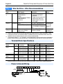
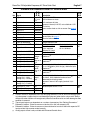
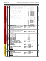
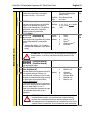
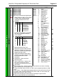
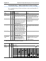
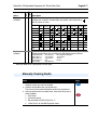
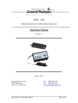
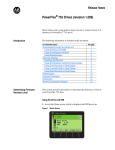
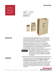
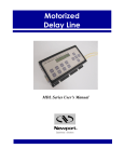
Quick Start
PowerFlex 70 Adjustable
Frequency AC Drive
When reading this document, look for this symbol “ Step x ” to guide
you through the 5 BASIC STEPS needed to install, start-up and
program the PowerFlex 70. The information provided Does Not
replace the User Manual and is intended for qualified drive service
personnel only. For detailed PowerFlex 70 information including
application considerations and related precautions refer to the following:
Title
Publication
PowerFlex 70 User Manual
20A-UM001…
PowerFlex Reference Manual PFLEX-RM001…
Available…
on the CD supplied with the drive or
at www.ab.com/manuals/dr
For Allen-Bradley Drives Technical Support:
Title
Allen-Bradley Drives Technical Support
Step 1
!
!
!
Online at…
www.ab.com/support/abdrives
Read the General Precautions
ATTENTION: This drive contains ESD (Electrostatic Discharge)
sensitive parts and assemblies. Static control precautions are required
when installing, testing, servicing or repairing this assembly.
Component damage may result if ESD control procedures are not
followed. If you are not familiar with static control procedures,
reference A-B publication 8000-4.5.2, “Guarding Against Electrostatic
Damage” or any other applicable ESD protection handbook.
ATTENTION: An incorrectly applied or installed drive can result in
component damage or a reduction in product life. Wiring or application
errors, such as, undersizing the motor, incorrect or inadequate AC
supply, or excessive ambient temperatures may result in malfunction of
the system.
ATTENTION: Only qualified personnel familiar with adjustable
frequency AC drives and associated machinery should plan or
implement the installation, start-up and subsequent maintenance of the
system. Failure to comply may result in personal injury and/or
equipment damage.
English-2
!
!
PowerFlex 70 Adjustable Frequency AC Drive Quick Start
ATTENTION: To avoid an electric shock hazard, verify that the
voltage on the bus capacitors has discharged before performing any
work on the drive. Measure the DC bus voltage at the +DC terminal of
the Power Terminal Block and the -DC test point (refer to the User
Manual for location). The voltage must be zero.
ATTENTION: Configuring an analog input for 0-20mA operation and
driving it from a voltage source could cause component damage. Verify
proper configuration prior to applying input signals.
!
ATTENTION: Hazard of personal injury or equipment damage exists
when using bipolar input sources. Noise and drift in sensitive input
circuits can cause unpredictable changes in motor speed and direction.
Use speed command parameters to help reduce input source sensitivity.
!
ATTENTION: Risk of injury or equipment damage exists. DPI or
SCANport host products must not be directly connected together via
1202 cables. Unpredictable behavior can result if two or more devices
are connected in this manner.
!
ATTENTION: The “adjust freq” portion of the bus regulator function
is extremely useful for preventing nuisance overvoltage faults resulting
from aggressive decelerations, overhauling loads, and eccentric loads. It
forces the output frequency to be greater than commanded frequency
while the drive’s bus voltage is increasing towards levels that would
otherwise cause a fault; however, it can also cause either of the
following two conditions to occur.
1. Fast positive changes in input voltage (more than a 10% increase
within 6 minutes) can cause uncommanded positive speed changes;
however an “OverSpeed Limit” fault will occur if the speed reaches
[Max Speed] + [Overspeed Limit]. If this condition is unacceptable,
action should be taken to 1) limit supply voltages within the
specification of the drive and, 2) limit fast positive input voltage
changes to less than 10%. Without taking such actions, if this operation
is unacceptable, the “adjust freq” portion of the bus regulator function
must be disabled (see parameters 161 and 162).
2. Actual deceleration times can be longer than commanded
deceleration times; however, a “Decel Inhibit” fault is generated if the
drive stops decelerating altogether. If this condition is unacceptable, the
“adjust freq” portion of the bus regulator must be disabled (see
parameters 161 and 162). In addition, installing a properly sized
dynamic brake resistor will provide equal or better performance in most
cases.
Note: These faults are not instantaneous and have shown test results
that take between 2 and 12 seconds to occur.
PowerFlex 70 Adjustable Frequency AC Drive Quick Start
English-3
EMC Instructions
CE Conformity(1)
Conformity with the Low Voltage (LV) Directive and Electromagnetic
Compatibility (EMC) Directive has been demonstrated using
harmonized European Norm (EN) standards published in the Official
Journal of the European Communities. PowerFlex Drives comply with
the EN standards listed below when installed according to the User and
Reference Manuals.
CE Declarations of Conformity are available online at:
http://www.ab.com/certification/ce/docs.
Low Voltage Directive (73/23/EEC)
•
EN50178 Electronic equipment for use in power installations.
EMC Directive (89/336/EEC)
•
EN61800-3 Adjustable speed electrical power drive systems Part 3:
EMC product standard including specific test methods.
General Notes
•
If the adhesive label is removed from the top of the drive, the drive
must be installed in an enclosure with side openings less than 12.5
mm (0.5 in.) and top openings less than 1.0 mm (0.04 in.) to maintain
compliance with the LV Directive.
•
The motor cable should be kept as short as possible in order to avoid
electromagnetic emission as well as capacitive currents.
•
Use of line filters in ungrounded systems is not recommended.
•
PowerFlex drives may cause radio interference if used in a
residential or domestic environment. The installer is required to take
measures to prevent interference, in addition to the essential
requirements for CE compliance listed below, if necessary.
•
Conformity of the drive with CE EMC requirements does not
guarantee an entire machine or installation complies with CE EMC
requirements. Many factors can influence total machine/installation
compliance.
•
PowerFlex drives can generate conducted low frequency
disturbances (harmonic emissions) on the AC supply system. More
information regarding harmonic emissions can be found in the
PowerFlex Reference Manual.
(1)
CE Certification testing has not been completed for 600 Volt class drives.
English-4
PowerFlex 70 Adjustable Frequency AC Drive Quick Start
Essential Requirements for CE Compliance
Conditions 1-6 listed below must be satisfied for PowerFlex drives to
meet the requirements of EN61800-3.
1. Standard PowerFlex 70 CE compatible Drive.
2. Review important precautions/attention statements throughout this
manual before installing drive.
3. Grounding as described on page 1-5 of the User Manual.
4. Output power, control (I/O) and signal wiring must be braided,
shielded cable with a coverage of 75% or better, metal conduit or
equivalent attenuation.
5. All shielded cables should terminate with the proper shielded
connector.
6. Conditions in Table A.
Frame(s)
Table A PowerFlex 70 EN61800-3 EMC Compatibility
A
B
C,
D,
E
(1)
Second Environment
Restrict Motor Internal
Cable to
Filter
Drive Description
40 m (131 ft.) Option
Drive Only
✔
with any Comm Option
✔
with Remote I/O
✔
Drive Only
✔
✔
with any Comm Option
✔
✔
with Remote I/O
✔
✔
Drive Only
✔
with any Comm Option
✔
with Remote I/O
✔
First Environment
External Input
Restricted
Filter
Ferrite (1) Distribution
✔
✔
✔
✔
✔
See PowerFlex
Reference Manual
✔
Input cables through a Ferrite Core (Frames A, B and C Fair-Rite #2643102002 or equivalent,
Frames D and E Fair-Rite #2643251002 or equivalent).
Step 2
Mount the Drive – Minimum Requirements
Minimum Mounting Clearances
76.2 mm
(3.0 in.)
76.2 mm
(3.0 in.)
Specified vertical clearance requirements are intended to be
from drive to drive. Other objects can occupy this space;
however, reduced airflow may cause protection circuits to
fault the drive. In addition, inlet air temperature must not
exceed the product specification.
Maximum Surrounding Air Temperature
Enclosure Rating
Temperature Range
Open Type, IP 20, NEMA Type 1 & Flange Mount 0 - 50°C (32 - 122°F)
IP54, IP 66 & NEMA Type 4X/12
0 - 40°C (32 - 104°F)
Important: Some drives are equipped with an adhesive label on the top of the
chassis. Removing the adhesive label from the drive changes the NEMA enclosure
rating from Type 1 Enclosed to Open Type.
PowerFlex 70 Adjustable Frequency AC Drive Quick Start
English-5
Dimensions
Table B PowerFlex 70 Frames
Output Power
kW
ND (HD)
0.37 (0.25)
0.75 (0.55)
1.5 (1.1)
2.2 (1.5)
4 (3)
5.5 (4)
7.5 (5.5)
11 (7.5)
15 (11)
18.5 (15)
22 (18.5)
30 (22)
37 (30)
HP
ND (HD)
0.5 (0.33)
1 (0.75)
2 (1.5)
3 (2)
5 (3)
7.5 (5)
10 (7.5)
15 (10)
20 (15)
25 (20)
30 (25)
40 (30)
50 (40)
Frame Size
208-240V AC Input
Not
IP66
Filtered Filtered (4X/12)
A
B
B
A
B
B
B
B
B
B
B
B
–
C
D
–
D
D
–
D
D
–
D
D
–
E
E
–
E
E
–
–
–
–
–
–
–
–
–
400-480V AC Input
Not
IP66
Filtered Filtered (4X/12)
A
B
B
A
B
B
A
B
B
B
B
B
B
B
B
–
C
D
–
C
D
–
D
D
–
D
D
–
D
D
–
D
D
–
E
E
–
E
E
Figure 1 PowerFlex 70 Frames A-E
IP20/66 (NEMA Type 1/4X/12)
A
D
600V AC Input
Not
Filtered Filtered
A
–
A
–
A
–
B
–
B
–
C
–
C
–
D
–
D
–
D
–
D
–
–
E
–
E
IP66
(4X/12)
B
B
B
B
B
D
D
D
D
D
D
E
E
Flange Mount
C
A
C
E
B
B
F
D
E
Dimensions are in millimeters and (inches).
Frame A
B
IP20 / NEMA Type 1
A
122.4 (4.82) 225.7 (8.89)
B
171.7 (6.76) 234.6 (9.24)
C
185.0 (7.28) 300.0 (11.81)
D
219.9 (8.66) 350.0 (13.78)
E
280.3 (11.04) 555.8 (21.88)
IP66 / NEMA Type 4X/12
B
171.7 (6.76) 239.8 (9.44)
D
219.9 (8.66) 350.0 (13.78)
E
280.3 (11.04) 555.8 (21.88)
Flange Mount
A
156.0 (6.14) 225.8 (8.89)
B
205.2 (8.08) 234.6 (9.24)
C
219.0 (8.62) 300.0 (11.81)
D
248.4 (9.78) 350.0 (13.78)
E
280.3 (11.04) 555.8 (21.88)
(1)
C
D
E
F
Weight (1)
kg (lbs.)
179.8 (7.08)
179.8 (7.08)
179.8 (7.08)
179.8 (7.08)
207.1 (8.15)
94.2 (3.71)
122.7 (4.83)
137.6 (5.42)
169.0 (6.65)
200.0 (7.87)
211.6 (8.33)
220.2 (8.67)
285.6 (11.25)
335.6 (13.21)
491.0 (19.33)
5.8 (0.23)
5.8 (0.23)
5.8 (0.23)
5.8 (0.23)
6.9 (0.27)
2.71 (6.0)
3.60 (7.9)
6.89 (15.2)
9.25 (20.4)
18.60 (41.0)
203.3 (8.00)
210.7 (8.29)
219.8 (8.65)
122.7 (4.83)
169.0 (6.65)
200.0 (7.87)
220.2 (8.67) 5.8 (0.23)
335.6 (13.21) 5.8 (0.23)
491.0 (19.33) 6.9 (0.27)
3.61 (8.0)
9.13 (20.1)
18.60 (41.0)
178.6 (7.03)
178.6 (7.03)
178.6 (7.03)
178.6 (7.03)
207.1 (8.15)
123.0 (4.84)
123.0 (4.84)
123.0 (4.84)
123.0 (4.84)
117.2 (4.61)
55.6 (2.19)
55.6 (2.19)
55.6 (2.19)
55.6 (2.19)
89.9 (3.54)
2.71 (6.0)
3.60 (7.9)
6.89 (15.2)
9.25 (20.4)
18.60 (41.0)
Weights include HIM and Standard I/O.
–
–
–
–
–
English-6
PowerFlex 70 Adjustable Frequency AC Drive Quick Start
Step 3
Wire the Drive – Wire Recommendations
Type
Power
Wire Type(s)
Description
• Four tinned copper
Standard 600V, 90°C (194°F)
conductors with XLPE
(1)
XHHW2/RHW-2
insulation.
Anixter
B209500-B209507, Belden • Copper braid/aluminum foil
combination shield and
29501-29507, or
tinned copper drain wire.
equivalent
• PVC jacket.
Signal
Standard Belden 8760/9460(or
0.750 mm2 (18AWG), twisted
(1) (2) (3)
Analog I/O equiv.)
pair, 100% shield with drain.
Belden 8770(or equiv.)
0.750 mm2 (18AWG), 3
cond., shielded for remote pot
only.
Digital I/O Shielded Multi-conductor shielded 0.750 mm2 (18AWG), 3
(1) (2) (3)
cable such as Belden
conductor, shielded.
8770(or equiv.)
(1)
(2)
(3)
Min. Insulation
Rating
300V,
75-90 degrees
C (167-194
degrees F)
300V,
60 degrees C
(140 degrees F)
Control and signal wires should be separated from power wires by at least 0.3 meters (1 foot).
If the wires are short and contained within a cabinet which has no sensitive circuits, the use of
shielded wire may not be necessary, but is always recommended.
I/O terminals labeled “(–)” or “Common” are not referenced to earth ground and are designed to
greatly reduce common mode interference. Grounding these terminals can cause signal noise.
Terminal Block Specifications
Name
Frame Description
Power Terminal A, B & Input power and
Block
C
motor connections
D
Input power and
motor connections
E
Input power and
motor connections
Wire Size Range (1)
Maximum Minimum
3.5 mm2 0.3 mm2
(12 AWG) (22 AWG)
8.4 mm2 0.8 mm2
(8 AWG) (18 AWG)
25.0 mm2 2.5 mm2
(3 AWG) (14 AWG)
I/O Terminal
Block
1.5 mm2 0.05 mm2 0.55 N-m 0.5 N-m
(16 AWG) (30 AWG) (4.9 lb.-in.) (4.4 lb.-in.)
All
Signal & control
connections
SHLD Terminal All
(1)
Terminating point
for wiring shields
—
—
Torque
Maximum
0.66 N-m
(5.5 lb.-in.)
1.7 N-m
(15 lb.-in.)
2.71 N-m
(24 lb.-in.)
Recommended
0.6 N-m
(5 lb.-in.)
1.4 N-m
(12 lb.-in.)
2.71 N-m
(24 lb.-in.)
1.6 N-m
1.6 N-m
(14 lb.-in.) (14 lb.-in.)
Maximum/minimum sizes that the terminal block will accept - these are not recommendations.
Power & Ground Wiring
L1
R
L2
S
L3
T
Required
Input Fusing
Required Branch
Circuit Disconnect
PE
PE
T1
U
T2
V
T3
W
+DC BRK
PowerFlex 70 Adjustable Frequency AC Drive Quick Start
English-7
No. Signal
Related
Param.
Factory
Default
Standard and Enhanced Control I/O Terminal Block
Description
361 Stop – CF 11.2 mA @ 24V DC
(CF = Clear 19.2V minimum on state
366
Fault)
3.2V maximum off state
Start
Important: Use only 24V DC, not suitable for 115V
Auto/Man
AC circuitry.
Speed Sel 1 Inputs can be wired as sink or source. See page 8.
Speed Sel 2
1
Digital In 1
2
Digital In 2
3
Digital In 3
4
Digital In 4
5
Digital In 5
6
Digital In 6
Speed Sel 3
7
24V Common
–
8
Digital In Common
–
Drive supplied power for Digital In1-6 inputs.
See examples on page 8.
150mA maximum load.
9
+24V DC
–
10
+10V Pot Reference
–
11
Digital Out 1 – N.O.(1)
12
Digital Out 1 Common
NOT Fault Max Resistive Load
250V AC / 30V DC
50 VA / 60 Watts
13
Digital Out 1 – N.C.(1)
Fault
14
17
Non-isolated, 0 to +10V, 10 bit, 100k ohm input
(3)
Voltage – impedance.
Reads
Analog In 1 (– Current) value at 14 Non-isolated, 4-20mA, 10 bit, 100 ohm input
impedance.(3)
Analog In 1 (+ Current) & 15
18
Analog In 2 (– Volts)
(2)
19
Analog In 2 (+ Volts)
20
Analog In 2 (– Current)
21
Analog In 2 (+ Current)
Voltage –
Reads
value at 18
& 19
22
10V Pot Common
Analog Out (– Volts)
Analog Out (– Current)
15
16
Analog In 1 (– Volts)
Analog Out (+ Volts)
Analog Out (+ Current)
24
Digital Out 2 – N.O.(1)
25
Digital Out 2 Common
26
Digital Out 2 – N.C.(1)
(2)
(3)
(4)
(5)
Max Inductive Load
250V AC / 30V DC
25 VA / 30 Watts
(2)
(2)
Output
Freq
Run
380 387
Minimum DC Load
10 µA, 10 mV DC
Analog In 1 (+ Volts)
23
(1)
2 k ohm minimum load.
320 327
Isolated, bipolar, differential, 0 to +10V unipolar (10
bit) or ±10V bipolar (10 bit & sign), 100k ohm input
impedance.(4)
Isolated, 4-20mA, 10 bit & sign, 100 ohm input
impedance.(4)
0 to +10V, 10 bit, 10k ohm (2k ohm minimum) load. 340 344
0 to 20mA, 10 bit, 400 ohm maximum load.(5)
Referenced to chassis ground.
Common if internal 10V supply (terminal 10) is
used.
See description at No.s 11-13.
380 387
NOT Run
Contacts shown in unpowered state. Any relay programmed as Fault or Alarm will energize (pick
up) when power is applied to drive and deenergize (drop out) when fault or alarm exists. Relays
selected for other functions will energize only when that condition exists and will deenergize when
condition is removed.
These inputs/outputs are dependent on a number of parameters. See “Related Parameters.”
Differential Isolation - External source must be less than 10V with respect to PE.
Differential Isolation - External source must be maintained at less than 160V with respect to PE.
Input provides high common mode immunity.
Analog output current is only available with Enhanced Control drives.
English-8
PowerFlex 70 Adjustable Frequency AC Drive Quick Start
Input/Output
Connection Example(3)
Potentiometer(1) [Speed Ref A Sel] = “Analog In 1”
10k Ohm Pot.
Potentiometer
Joystick
Recommended
14
(2k Ohm minimum)
15
Joystick(1)
±10V Input 100k ohm input
22
10
impedance
Related
Param.
I/O Wiring Examples
090
to
095
18
22
-10V Com +10V
Power Source
[Speed Ref A Sel] = “Analog In 2”
Analog Input
Bipolar(1)
Unipolar (Voltage)
Unipolar (Current)
Bipolar:
±10V
–
Unipolar:
18 Common
18 Common
+
+
+
0 to +10V, 100k
19
19
ohm impedance
4-20 mA, 100 ohm
impedance
Analog Output
Digital N.O. / N.C. Output
Analog/Digital
Output
11
0 to +10V Output 12
Can drive a 2k
13
Ohm load (25 mA
24
or
short circuit current
+
–
25
22
limit)
23
320
to
327
19
361
to
366
20
21
2 Wire Control(2) - 24V DC Input(4): [Digital In2 Sel] = “Run”
Non-Reversing
Internal Supply
External Supply
Requires 2-wire
functions only
2
2
([Digital In1 Sel]).
Stop-Run
Stop-Run
Using 3-wire selec7
tions will cause a
8
8
type 2 alarm.
9
3 Wire Control
Requires 3-wire
functions only
([Digital In1 Sel]).
Using 2-wire selections will cause a
type 2 alarm.
(2)
(3)
(4)
361
to
366
Common
24V DC Input(4): [Digital In1 Sel] = “Stop – CF”, [Digital In2 Sel] = “Start”
Internal Supply
External Supply
Stop
1
2
Stop
Start
7
8
9
Start
1
2
8
+24V
(1)
380
to
387
26
Power
Source
+24V
341
to
344
Common
Refer to the Attention statement on page 2 for important bipolar wiring information.
Important: Programming inputs for 2 wire control deactivates all HIM Start buttons.
Examples show hardware wiring only. Refer to page 7 for parameters that must be adjusted.
If desired, a User Supplied 24V DC power source can be used. Refer to the “External” example.
PowerFlex 70 Adjustable Frequency AC Drive Quick Start
Step 4
English-9
Start-Up Check List
❏ 1. Verify input supply voltage.
❏ 2. Check output wiring.
❏ 3. Check control wiring.
❏ 4. Apply AC power and control voltages to the drive.
If any of the six digital inputs are configured to Stop – CF
(CF = Clear Fault) or Enable, verify that signals are present or the
drive will not start. Refer to Troubleshooting – Abbreviated Fault &
Alarm Listing on page 16 for a list of potential digital input conflicts.
If the STS LED is not flashing green at this point, refer to Status
Indicators on page 9.
❏ 5. Select Start-Up method: SMART Start or Assisted Start-Up.
Status Indicators
Name
STS
PORT
MOD
NET A
NET B
Color
Green
State
Flashing
Steady
Yellow
Flashing,
Drive Stopped
Flashing,
Drive Running
Steady,
Drive Running
Red
Flashing
Steady
Refer to the Communication
Adapter User Manual.
Description
Drive ready, but not running and no faults are present.
Drive running, no faults are present.
An inhibit condition exists, the drive cannot be started.
Check parameter 214 [Start Inhibits].
An intermittent type 1 alarm condition is occurring.
Check parameter 211 [Drive Alarm 1].
A continuous type 1 alarm condition exists.
Check parameter 211 [Drive Alarm 1].
A fault has occurred.
A non-resettable fault has occurred.
Status of DPI port internal communications (if present).
Status of communications module (when installed).
Status of network (if connected).
Status of secondary network (if connected).
English-10
Step 5
PowerFlex 70 Adjustable Frequency AC Drive Quick Start
Monit
Program the Drive – Parameter Files & Groups
or
Motor
File A
Metering
Drive Data
Motor Data
Torq Attributes
Volts per Hertz
Speed Feedback*
Speed
Contr
ol
Dynam
Comm
trol
File C
File B
Spd Mode & Limits
Speed References
Discrete Speeds
Speed Trim
Slip Comp
Process PI
Speed Regulator*
Comm
File D
Ramp Rates
Load Limits
Stop/Brake Modes
Restart Modes
Power Loss
Inputs
unica
Utility
ic Con
and
tion
& Outp
uts
File J
File H
File E
Direction Config
HIM Ref Config
MOP Config
Drive Memory
Diagnostics
Faults
Alarms
*Enhanced Control Only.
Analog Inputs
Analog Outputs
Digital Inputs
Digital Outputs
Comm Control
Masks & Owners
Datalinks
Security*
Frequently Used Parameters
041 [Motor NP Volts]
Set to the motor nameplate rated volts.
042 [Motor NP FLA]
Default:
Drive Rating Based
Min/Max: 0.0/[Rated Volts]
Units:
0.1 VAC
Default: Drive Rating Based
MOTOR CONTROL (File B)
Motor Data
Set to the motor nameplate rated full load Min/Max: 0.0/[Rated Amps] × 2
amps.
Units:
0.1 Amps
Default: Drive Rating Based
045 [Motor NP Power]
046
Set to the motor nameplate rated power. Min/Max: 0.00/100.00
0.00/412.48 E C
32
Units:
0.01 kW/HP
See [Mtr NP Pwr Units]
Default:
Drive Rating Based
046 [Mtr NP Pwr Units]
Selects the motor power units to be used. Options:
Torq Attributes
047
048
0
“Horsepower”
1
“kiloWatts”
Motor NP Hz/3
047 [Motor OL Hertz]
Default:
Selects the output frequency below
which the motor operating current is
derated. The motor thermal overload will
generate a fault at lower levels of current.
053 Standard [Torque Perf Mode]
Sets the method of motor torque
production.
Min/Max: 0.0/500.0 Hz
Units:
0.1 Hz
Default:
0
“Sensrls Vect”
Options:
0
1
2
3
0
“Sensrls Vect”
“SV Economize”
“Custom V/Hz”
“Fan/Pmp V/Hz”
“Sensrls Vect”
0
1
2
3
4
“Sensrls Vect”
“SV Economize”
“Custom V/Hz”
“Fan/Pmp V/Hz”
“FVC Vector”(1)
Default:
[Motor Cntl Sel]
EC
Sets the method of motor control used in Options:
the drive.
Important: “FVC Vector” mode requires
autotuning of the motor, both coupled
and uncoupled to the load.
(1)
Enhanced firmware 2.001 & later.
042
220
062
063
069
070
PowerFlex 70 Adjustable Frequency AC Drive Quick Start
English-11
Torq Attributes
MOTOR CONTROL (File B)
061 [Autotune]
Default: 3
“Calculate”
053
062
Provides a manual or automatic method Options: 0
“Ready”
for setting [IR Voltage Drop] and [Flux
1
“Static Tune”
Current Ref], which affect sensorless
2
“Rotate Tune”
vector performance. Valid only when
3
“Calculate”
parameter 53 is set to “Sensrls Vect” or
“SV Economize.”
“Ready” (0) = Parameter returns to this setting following a “Static Tune” or “Rotate
Tune.” It also permits manually setting [IR Voltage Drop] and [Flux Current Ref].
“Static Tune” (1) = A temporary command that initiates a non-rotational motor
stator resistance test for the best possible automatic setting of [IR Voltage Drop].
A start command is required following initiation of this setting. The parameter
returns to “Ready” (0) following the test, at which time another start transition is
required to operate the drive in normal mode. Used when motor cannot be
rotated.
“Rotate Tune” (2) = A temporary command that initiates a “Static Tune” followed
by a rotational test for the best possible automatic setting of [Flux Current Ref]. A
start command is required following initiation of this setting. The parameter
returns to “Ready” (0) following the test, at which time another start transition is
required to operate the drive in normal mode. Important: Used when motor is
uncoupled from the load. Results may not be valid if a load is coupled to the motor
during this procedure.
!
ATTENTION: Rotation of the motor in an undesired direction can
occur during this procedure. To guard against possible injury and/or
equipment damage, it is recommended that the motor be
disconnected from the load before proceeding.
“Calculate” (3) = This setting uses motor nameplate data to automatically set [IR
Voltage Drop] and [Flux Current Ref].
Default: 0
“Open Loop”
121
080 Standard [Speed Mode]
thru
Sets the method of speed regulation.
Options: 0
“Open Loop”
138
1
“Slip Comp”
2
“Process PI”
“Open Loop”
Default: 0
[Feedback Select]
EC
Spd Mode & Limits
SPEED COMMAND (File C)
Selects the source for motor speed
feedback. Note that all selections are
available when using Process PI.
0
1
2
3
4
5
Default:
0.0 Hz
“Open Loop” (0) - no encoder is present,
and slip compensation is not needed.
“Slip Comp” (1) - tight speed control is
needed, and encoder is not present.
“Encoder” (3) - an encoder is present.
“Simulator” (5) - Simulates a motor for
testing drive operation & interface check.
081 [Minimum Speed]
Sets the low limit for speed reference
after scaling is applied. Refer to
parameter 083 [Overspeed Limit].
082 [Maximum Speed]
Sets the high limit for speed reference
after scaling is applied. Refer to
parameter 083 [Overspeed Limit].
“Open Loop”
“Slip Comp”
“Reserved”
“Encoder”
“Reserved”
“Simulator”
Options:
Min/Max: 0.0/[Maximum Speed]
Units:
0.1 Hz
Default:
50.0 or 60.0 Hz
(Dependent on voltage
class)
Min/Max: 5.0/400.0 Hz
5.0/500.0 Hz
Units:
0.0 Hz
EC
092
095
055
083
091
094
202
English-12
PowerFlex 70 Adjustable Frequency AC Drive Quick Start
090 [Speed Ref A Sel]
Default:
Selects the source of the speed
Options:
reference to the drive unless [Speed Ref
B Sel] or [Preset Speed 1-7] is selected.
Speed References
for DPI port locations.
(2) Enhanced Control Drives Only.
Default:
“Analog In 2”
“Analog In 1”
1
“Analog In 2”
2
3-8 “Reserved”
“MOP Level”
9
10 “Reserved”
11 “Preset Spd1”
12 “Preset Spd2”
13 “Preset Spd3”
14 “Preset Spd4”
15 “Preset Spd5”
16 “Preset Spd6”
17 “Preset Spd7”
18 “DPI Port 1”(1)
19 “DPI Port 2”(1)
20 “DPI Port 3”(1)
21 “Reserved”
22 “DPI Port 5”(1)
23- “Reserved”
29
30 “HighRes Ref”(2)
[Maximum Speed]
Scales the upper value of the [Speed Ref Min/Max: –/+[Maximum Speed]
A Sel] selection when the source is an
Units:
0.1 Hz
analog input.
Default: 0.0 Hz
092 [Speed Ref A Lo]
101
102
103
104
105
106
107
140
141
Scales the lower value of the [Speed Ref Min/Max: –/+[Maximum Speed]
A Sel] selection when the source is an
Units:
0.1 Hz
analog input.
Default: 5.0 Hz
[Preset Speed 1]
10.0 Hz
[Preset Speed 2]
20.0 Hz
[Preset Speed 3]
30.0 Hz
[Preset Speed 4]
40.0 Hz
[Preset Speed 5]
50.0 Hz
[Preset Speed 6]
60.0 Hz
[Preset Speed 7]
Provides an internal fixed speed
Min/Max: –/+[Maximum Speed]
command value. In bipolar mode
0.1 Hz
Units:
direction is commanded by the sign of
the reference.
Default: 10.0 Secs
[Accel Time 1]
[Accel Time 2]
10.0 Secs
Sets the rate of accel for all speed
increases.
Ramp Rates
DYNAMIC CONTROL (File D)
(1) See Appendix B of the User Manual
091 [Speed Ref A Hi]
Discrete Speeds
SPEED COMMAND (File C)
For more information on selecting a
speed reference source, refer to the
PowerFlex 70 User Manual, “Speed
Reference Control”.
2
Min/Max: 0.1/3600.0 Secs
Units:
0.1 Secs
Max Speed
= Accel Rate
Accel Time
142 [Decel Time 1]
143 [Decel Time 2]
Sets the rate of decel for all speed
decreases.
Max Speed
= Decel Rate
Decel Time
Default:
10.0 Secs
10.0 Secs
Min/Max: 0.1/3600.0 Secs
Units:
0.1 Secs
002
091
thru
093
101
thru
107
117
thru
120
192
thru
194
213
272
273
320
361
thru
366
082
081
090
093
142
143
146
361
thru
366
140
141
146
361
thru
366
PowerFlex 70 Adjustable Frequency AC Drive Quick Start
148 [Current Lmt Val]
Default:
151 [PWM Frequency]
Sets the carrier frequency for the PWM
output. Drive derating may occur at
higher carrier frequencies. For derating
information, refer to the PowerFlex
Reference Manual, publication
PFLEX-RM001….
155 Standard [Stop Mode A]
156 Standard [Stop Mode B]
Active stop mode. [Stop Mode A] is active
unless [Stop Mode B] is selected by
inputs.
(1) When using options 1 or 2, refer to
the Attention statements at [DC Brake
Level].
!
Stop/Brake Modes
DYNAMIC CONTROL (File D)
Load Limits
Defines the current limit value when
[Current Lmt Sel] = “Cur Lim Val.”
E C v2
E C v2
English-13
[Rated Amps] × 1.5
(Equation approximates
default value.)
147
149
Min/Max: Drive Rating Based
Units:
0.1 Amps
Default: 4 kHz
Min/Max: 2, 3, 4, 5, 6, 7, 8, 9, 10 kHz
2, 4, 8, 12 kHz E C
Units:
1 kHz
Default:
Default:
1
0
“Ramp”
“Coast”
Options:
0
1
2
3
“Coast”
“Ramp”(1)
“Ramp to Hold”(1)
“DC Brake”
155
156
ATTENTION: If a hazard of injury do to movement of equipment or
material exists, an auxiliary mechanical braking device must be
used.
[Stop/Brk Mode A]
[Stop/Brk Mode B]
See description above.
Default:
1
4
“Adjust Freq”
“Both-Frq 1st”
Sets the method and sequence of the DC Options:
bus regulator voltage. Choices are
dynamic brake, frequency adjust or both.
Sequence is determined by programming
or digital input to the terminal block.
Dynamic Brake Setup
If a dynamic brake resistor is connected
to the drive, both these parameters must
be set to either option 2, 3 or 4.
Refer to the Attention statement on page
2 for important information on bus
regulation.
0
1
2
3
4
“Disabled”
“Adjust Freq”
“Dynamic Brak”
“Both-DB 1st”
“Both-Frq 1st”
161 [Bus Reg Mode A]
162 [Bus Reg Mode B]
!
ATTENTION: The drive does not offer protection for externally
mounted brake resistors. A risk of fire exists if external braking
resistors are not protected. External resistor packages must be
self-protected from over temperature or a protective circuit must be
supplied. See the PowerFlex 70 User Manual for more information.
160
163
English-14
PowerFlex 70 Adjustable Frequency AC Drive Quick Start
Stop/Brake Modes
!
Drive Memory
UTILITY (File E)
0
2
“Internal Res”
“None” E C
0
1
2
“Internal Res”
“External Res”
“None”
161
162
ATTENTION: The drive does not offer protection for externally
mounted brake resistors. A risk of fire exists if external braking
resistors are not protected. External resistor packages must be
self-protected from over temperature or the protective circuit shown
in Appendix C of the User Manual, or equivalent, must be supplied.
Default:
0
“Disabled”
Enables/disables the function which
Options:
reconnects to a spinning motor at actual
RPM when a start command is issued.
0
1
“Disabled”
“Enabled”
Default:
0
“Not Selected”
169 [Flying Start En]
201 [Language]
Selects the display language when using Options:
an LCD HIM. This parameter is not
functional with an LED HIM.
Analog Inputs
322 [Analog In 1 Hi]
325 [Analog In 2 Hi]
INPUTS & OUTPUTS (File J)
Default:
Selects whether the internal or an
external DB resistor will be used.
Options:
If a dynamic brake resistor is connected
to the drive, [Bus Reg Mode A & B] must
be set to either option 2, 3 or 4.
ATTENTION: Equipment damage may result if a drive mounted
(internal) resistor is installed and this parameter is set to “External
Res.” Thermal protection for the internal resistor will be disabled,
resulting in possible device damage.
Restart Modes
DYNAMIC CONTROL (File D)
163 [DB Resistor Type]
Default:
“Not Selected”
0
“English”
1
“Français”
2
“Español”
3
“Italiano”
4
“Deutsch”
5
“Reserved”
6
“Português”
7
8-9 “Reserved”
10 “Nederlands”
10.000 Volt
10.000 Volt
Sets the highest input value to the analog Min/Max: 4.000/20.000 mA Standard ,
input x scaling block.
0.000/20.000 mA E C ,
–/+10.000V,
0.000/10.000V
0.001 mA,
Units:
0.001 Volt
Default: 0.000 Volt
323 [Analog In 1 Lo]
0.000 Volt
326 [Analog In 2 Lo]
Sets the lowest input value to the analog Min/Max: 4.000/20.000 mA,
input x scaling block.
0.000/10.000V (No. 323),
Units:
–/+10.000V (No. 326)
0.000/10.000V,
0.001 mA,
0.001 Volt
170
091
092
091
092
PowerFlex 70 Adjustable Frequency AC Drive Quick Start
361 [Digital In1 Sel]
[Digital In2 Sel]
362 [Digital In3 Sel]
363 [Digital In4 Sel]
364 [Digital In5 Sel]
365 [Digital In6 Sel]
366 Selects the function for the digital inputs.
(1)
3
0
0
0
0
1
1
1
1
2
0
0
1
1
0
0
1
1
1
0
1
0
1
0
1
0
1
“Speed Sel 1-3”
Reference A
Reference B
Preset Speed 2
Preset Speed 3
Preset Speed 4
Preset Speed 5
Preset Speed 6
Preset Speed 7
To access Preset Speed 1, set [Speed
Ref A Sel] or [Speed Ref B Sel] to
“Preset Speed 1”.
(3)
Digital Inputs
INPUTS & OUTPUTS (File J)
(2)
When [Digital Inx Sel] is set to option
2 “Clear Faults” the Stop button
cannot be used to clear a fault
condition.
3
0
0
0
0
1
1
1
1
2
0
0
1
1
0
0
1
1
1
0
1
0
1
0
1
0
1
“Spd/Trq Sel1-3”
Zero Torque
Spd Reg
Torque Reg
Min Spd/Trq
Max Spd/Trq
Sum Spd/Trq
Absolute
Zero Trq
(4) Enhanced Control Drives Only.
(5) Enhanced Firmware V2.001 and later.
(6)
English-15
Default:
Default:
Default:
Default:
Default:
Default:
4
5
18
15
16
17
“Stop – CF”(1)
“Start”
“Auto/ Manual”
“Speed Sel 1”
“Speed Sel 2”
“Speed Sel 3”
Options:
0
1
2
3
4
5
6
7
8
9
10
11
12
13
14
15-17
18
19
20
21
22
23
24
25
26
27
28
29
30
31-33
34
35
36-40
41-42
43
44
45
46
“Not Used”
“Enable”(6)
“Clear Faults”(1)
“Aux Fault”
“Stop – CF”(1)
“Start”(9)(11)
“Fwd/ Reverse”(9)
“Run”(10)
“Run Forward”(3)
“Run Reverse”(3)
“Jog”(9) “Jog1”(4)
“Jog Forward”
“Jog Reverse”
“Stop Mode B”
“Bus Reg Md B”
“Speed Sel 1-3”(2)
“Auto/ Manual”(8)
“Local”
“Acc2 & Dec2”
“Accel 2”
“Decel 2”
“MOP Inc”(12)
“MOP Dec”(12)
“Excl Link”(12)
“PI Enable”
“PI Hold”
“PI Reset”
“Reserved”
“Precharge En”(4)(12)
“Spd/Trq Sel1-3” (5)
“Jog 2”(4)
“PI Invert”(4)
“Reserved”
“UserSet Sel1-2” (5)
“Run Level” (5)(12)
“RunFwd Level” (5)(12)
“RunRev Level” (5)(12)
“Run w/Comm” (5)(12)
Opening an “Enable” input will cause
the motor to coast-to-stop, ignoring any
programmed Stop modes.
(7) A dedicated hardware enable input is
available via a jumper selection. Refer
to the User Manual for further
information.
(8) Auto/Manual - Refer to the User
Manualfor details.
(9) Typical 3-Wire Inputs - Requires that
only 3-wire functions are chosen.
Including 2-wire selections will cause a
type 2 alarm.
(10)Typical 2-Wire Inputs - Requires that only 2-wire functions are chosen. Including
3-wire selections will cause a type 2 alarm.
(11)A “Dig In ConflictB” alarm will occur if a “Start” input is programmed without a “Stop”
input.
Type 2 Alarms - Some digital input programming may cause conflicts that will result
in a Type 2 alarm. Example: [Digital In1 Sel] set to 5 “Start” in 3-wire control and
[Digital In2 Sel] set to 7 “Run” in 2-wire.
Refer to the User Manual for information on resolving this type of conflict.
(12) Refer to Option Definitions in the User Manual.
100
156
162
096
140
194
380
124
English-16
PowerFlex 70 Adjustable Frequency AC Drive Quick Start
Troubleshooting – Abbreviated Fault & Alarm Listing
Type(1)
No.
For a complete listing of Faults and Alarms, refer to the PowerFlex 70
User Manual.
Fault
Auxiliary Input
2
Motor Overload
7
➀
➀
➂
OverSpeed Limit
25
➀
SW OverCurrent
36
➀
IR Volts Range
77
FluxAmpsRef
Rang
78
Action
Check remote wiring.
Internal electronic overload trip. An excessive motor load exists.
Enable/Disable with [Fault Config Reduce load so drive output current
does not exceed the current set by
1].
[Motor NP FLA].
Remove excessive load or
Functions such as Slip
Compensation or Bus Regulation overhauling conditions or increase
have attempted to add an output [Overspeed Limit].
frequency adjustment greater
than that programmed in
[Overspeed Limit].
Check for excess load, improper DC
Drive output current has
exceeded the 1ms current rating. boost setting. DC brake volts set too
This rating is greater than the 3 high.
second current rating and less
than the hardware overcurrent
fault level. It is typically 200-250%
of the drive continuous rating.
“Calculate” is the autotune default Re-enter motor nameplate data.
and the value determined by the
autotune procedure for IR Drop
Volts is not in the range of
acceptable values.
1. Reprogram [Motor NP FLA] with
The value for flux amps
the correct motor nameplate
determined by the Autotune
value.
procedure exceeds the
programmed [Motor NP FLA].
2. Repeat Autotune.
Alarm
Dig In
ConflictA
17
Type(1)
See the User Manual for a description of fault types.
No.
(1)
Description
Auxiliary input interlock is open.
➁
Description
Digital input functions are in conflict. Combinations marked with a “ ” will
cause an alarm.
Acc2/Dec2 Accel 2
Acc2 / Dec2
Accel 2
Decel 2
Jog
Jog Fwd
Jog Rev
Fwd / Rev
Decel 2
Jog
Jog Fwd Jog Rev Fwd/Rev
18
Type(1)
Alarm
Dig In
ConflictB
No.
PowerFlex 70 Adjustable Frequency AC Drive Quick Start
➁
English-17
Description
A digital Start input has been configured without a Stop input or other
functions are in conflict. Combinations that conflict are marked with a “ ”
and will cause an alarm.
Fwd/
Start Stop–CF Run Run Fwd Run Rev Jog Jog Fwd Jog Rev Rev
Start
Stop–CF
Run
Run Fwd
Run Rev
Jog
Jog Fwd
Jog Rev
Fwd /
Rev
Dig In
ConflictC
19
➁
More than one physical input has been configured to the same input function.
Multiple configurations are not allowed for the following input functions.
Forward/Reverse
Speed Select 1
Speed Select 2
Speed Select 3
Run Forward
(1)
Run Reverse
Jog Forward
Jog Reverse
Run
Stop Mode B
Bus Regulation Mode B
Acc2 / Dec2
Accel 2
Decel 2
See User Manual for a description of alarm types.
Manually Clearing Faults
Step
1. Press Esc to acknowledge the fault. The fault information will be
removed so that you can use the HIM.
2. Address the condition that caused the fault.
The cause must be corrected before the fault can be cleared.
3. After corrective action has been taken, clear the fault by one of
these methods:
• Press Stop
• Cycle drive power
• Set parameter 240 [Fault Clear] to “1.”
• “Clear Faults” on the HIM Diagnostic menu.
Key(s)
Esc
www.rockwellautomation.com
Corporate Headquarters
Rockwell Automation, 777 East Wisconsin Avenue, Suite 1400, Milwaukee, WI, 53202-5302 USA, Tel: (1) 414.212.5200, Fax: (1) 414.212.5201
Headquarters for Allen-Bradley Products, Rockwell Software Products and Global Manufacturing Solutions
Americas: Rockwell Automation, 1201 South Second Street, Milwaukee, WI 53204-2496 USA, Tel: (1) 414.382.2000, Fax: (1) 414.382.4444
Europe/Middle East/Africa: Rockwell Automation SA/NV, Vorstlaan/Boulevard du Souverain 36, 1170 Brussels, Belgium, Tel: (32) 2 663 0600, Fax: (32) 2 663 0640
Asia Pacific: Rockwell Automation, 27/F Citicorp Centre, 18 Whitfield Road, Causeway Bay, Hong Kong, Tel: (852) 2887 4788, Fax: (852) 2508 1846
Headquarters for Dodge and Reliance Electric Products
Americas: Rockwell Automation, 6040 Ponders Court, Greenville, SC 29615-4617 USA, Tel: (1) 864.297.4800, Fax: (1) 864.281.2433
Europe/Middle East/Africa: Rockwell Automation, Brühlstraße 22, D-74834 Elztal-Dallau, Germany, Tel: (49) 6261 9410, Fax: (49) 6261 17741
Asia Pacific: Rockwell Automation, 55 Newton Road, #11-01/02 Revenue House, Singapore 307987, Tel: (65) 6356-9077, Fax: (65) 6356-9011
U.S. Allen-Bradley Drives Technical Support
Tel: (1) 262.512.8176, Fax: (1) 262.512.2222, Email: [email protected], Online: www.ab.com/support/abdrives
Publication 20A-QS001E-EN-P – February 2005
Supersedes June 2004
P/N 198682-P05
Copyright © 2005 Rockwell Automation, Inc. All rights reserved. Printed in USA.