1
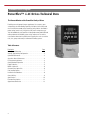
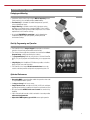
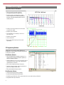
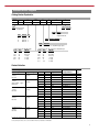
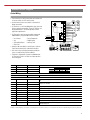
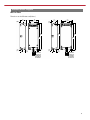
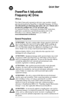
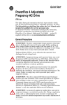
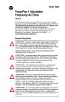
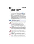
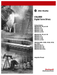
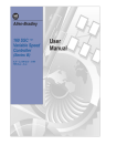
Technical Data
PowerFlex 4
AC Drives
Standard Drives Program
PowerFlex™ 4 AC Drives Technical Data
The Newest Member of the PowerFlex Family of Drives
Providing users with powerful motor speed control in a compact, space
saving design, the Allen-Bradley PowerFlex 4 AC drive is the smallest and
most cost-effective member of the PowerFlex family of drives. Available in
power ratings from 0.2 to 3.7 kW (0.25 to 5 HP) and in voltage classes of
120, 240 and 480 volts, the PowerFlex 4 is designed to meet global OEM and
end-user demands for flexibility, space savings and ease of use and is a
cost-effective alternative for speed control of applications such as machine
tools, fans, pumps and conveyors and material handling systems.
Table of Contents
Description
Page
Packaging and Mounting . . . . . . . . . . . . . . . . . . . . . . . . . . . . . . . . . . . 3
Start Up, Programming and Operation . . . . . . . . . . . . . . . . . . . . . . . . . 3
Optimized Performance . . . . . . . . . . . . . . . . . . . . . . . . . . . . . . . . . . . . 3
Sensorless Vector Performance . . . . . . . . . . . . . . . . . . . . . . . . . . . . . . 4
PC Programming Software . . . . . . . . . . . . . . . . . . . . . . . . . . . . . . . . . . 4
Catalog Number Explanation . . . . . . . . . . . . . . . . . . . . . . . . . . . . . . . . 5
Product Selection . . . . . . . . . . . . . . . . . . . . . . . . . . . . . . . . . . . . . . . . . 5
NEMA 1 Option Kit . . . . . . . . . . . . . . . . . . . . . . . . . . . . . . . . . . . . . . . . 6
Communication Option Kits . . . . . . . . . . . . . . . . . . . . . . . . . . . . . . . . . 6
User Installed Options . . . . . . . . . . . . . . . . . . . . . . . . . . . . . . . . . . . . . 7
Installation Considerations. . . . . . . . . . . . . . . . . . . . . . . . . . . . . . . . . . 8
Control Wiring . . . . . . . . . . . . . . . . . . . . . . . . . . . . . . . . . . . . . . . . . . . 9
Specifications . . . . . . . . . . . . . . . . . . . . . . . . . . . . . . . . . . . . . . . . . . . 10
Parameter Descriptions . . . . . . . . . . . . . . . . . . . . . . . . . . . . . . . . . . . 12
Approximate Dimensions . . . . . . . . . . . . . . . . . . . . . . . . . . . . . . . . . . 13
2
Standard Drives Program
Packaging and Mounting
• Installation can be a virtual snap using the DIN rail mounting feature.
Panel mounting is also available providing added flexibility.
• Zero Stacking™ is allowable for ambient temperatures up to 40°C,
saving valuable panel space.
• Integral filtering is available on select 230V single phase ratings,
providing a cost-effective means of meeting EN55011, Class A and B
EMC requirements. External filters provide compliance to Class A and B
requirements for all PowerFlex 4 ratings.
• An optional IP30 (NEMA 1) conduit box is easily adapted to the
standard IP20 (NEMA Type Open) product, providing increased
environmental ratings.
Start Up, Programming and Operation
• The PowerFlex 4 has an integral keypad that provides out of the box
operation using the local potentiometer and control keys.
• The 10 most common application parameters are contained in the Basic
Program Group, making programming fast and easy.
• The programming keys have the same function as all other PowerFlex
drives, so if you can program one PowerFlex drive, you can program them
all.
• 4 digit display with 10 additional LED indicators provides an intuitive
display of drive status and information.
• The PowerFlex 4 has integral RS-485 communications that can be
used in a multi-drop network configuration or programming from a PC.
Optimized Performance
• Removable MOV to ground provides trouble-free operation when used
on ungrounded distribution systems.
• A relay pre-charge limits inrush current.
• Integral brake resistor, available on 0.75 kW (1.0 HP) units and larger,
provides dynamic braking capability with simple low cost brake resistors.
• DIP switch settable 24V DC sink or source control for control wiring
flexibility.
• 150% overload for 60 seconds or 200% overload for 3 seconds provides
robust overload protection.
• Adjustable PWM frequency up to 16 kHz ensures quiet operation.
3
Standard Drives Program
Sensorless Vector Performance
• Drive automatically provides auto boost
(IR compensation) and slip compensation.
• Provides excellent speed regulation and high
levels of torque across the entire speed range of
the drive, and improved speed regulation even as
loading increases.
• At 100% motor load, the drive will run the motor
at synchronous speed.
• Excellent current regulation.
• The PowerFlex 4 has the ability to start into at
least 150% load.
• Excellent starting torque.
• Linear acceleration.
• Best in class digital input response time and
repeatability.
PC Programming Software
Through the use of a Serial Converter Module and
DriveExplorer or Drive Executive software, programming
can be greatly simplified.
DriveExplorer Software
• View and modify drive and adapter parameters in a
method similar to the file management capability of
Microsoft Windows Explorer.
• Operate the drive via an on-screen Control Bar, which is
a tool that allows you to start, stop, and change the
speed reference of the drive.
• Save, restore and print parameter information.
• Compare current parameters with factory defaults or
previously saved parameter values.
• Edit, upload and download parameters.
DriveExecutive Software
•
•
•
•
4
Online and offline programming capability
In-grid and dialog-based parameter editing
Immediate visual indication of drive and communication status when viewing online drive
Integrated HTML Help architecture
Standard Drives Program
Catalog Number Explanation
22A
-
A
1P5
N
1
1
4
Drive
Dash
Voltage Rating
Rating
Enclosure
HIM
Emission Class
Comm Slot
Code
22A
Code
4
PowerFlex 4
Code
V
A
B
D
Voltage
120V AC
240V AC
240V AC
480V AC
Code
0
1
Ph.
1
1
3
3
Code
1
Code
N
Output Current @ 380-480V Input
Code Amps
kW (HP)
1P4
1.4
0.37 (0.5)
2P3
2.3
0.75 (1.0)
4P0
4.0
1.5 (2.0)
6P0
6.0
2.2 (3.0)
8P7
8.7
3.7 (5.0)
Version
RS485
Rating
No Filter
Integral EMI Filter
Interface Module
Fixed Keypad
Enclosure
Panel Mount - IP 20 (NEMA Type Open)
Output Current @ 100-120 Input or 200-240V Input
Code Amps
kW (HP)
1P5
1.5
0.2 (0.25)
2P3
2.3
0.37 (0.5)
4P5
4.5
0.75 (1.0)
8P0
8.0
1.5 (2.0)
012
12
2.2 (3.0)
017
17.5
3.7 (5.0)
Product Selection
Drive Ratings
Input Voltage
100-120V 50/60 Hz
1-Phase
No Filter
Output Voltage
0-230V
3-Phase
200-240V 50/60 Hz
1-Phase
With Integral “S Type”
EMC Filter
0-230V
3-Phase
200-240V 50/60 Hz
1-Phase
No Filter
0-230V
3-Phase
200-240V 50/60 Hz
3-Phase
No Filter
0-230V
3-Phase
380-480V 50/60 Hz
3-Phase
No Filter
0-460V
3-Phase
kW
0.2
0.37
0.75
0.2
0.37
0.75
1.5
0.2
0.37
0.75
1.5
0.2
0.37
0.75
1.5
2.2
3.7
0.37
0.75
1.5
2.2
3.7
HP
0.25
0.5
1.0
0.25
0.5
1.0
2.0
0.25
0.5
1.0
2.0
0.25
0.5
1.0
2.0
3.0
5.0
0.5
1.0
2.0
3.0
5.0
Output Current
1.5A
2.3A
4.5A
1.5A
2.3A
4.5A
8.0A
1.5A
2.3A
4.5A
8.0A
1.5A
2.3A
4.5A
8.0A
12.0A
17.5
1.4A
2.3A
4.0A
6.0A
8.7A
Catalog Number ➀
22A-V1P5N104
22A-V2P3N104
22A-V4P5N104
22A-A1P5N114
22A-A2P3N114
22A-A4P5N114
22A-A8P0N114
22A-A1P5N104
22A-A2P3N104
22A-A4P5N104
22A-A8P0N104
22A-B1P5N104
22A-B2P3N104
22A-B4P5N104
22A-B8P0N104
22A-B012N104
22A-B017N104
22A-D1P4N104
22A-D2P3N104
22A-D4P0N104
22A-D6P0N104
22A-D8P7N104
Frame
Size
A
A
B
A
A
A
B
A
A
A
B
A
A
A
A
B
B
A
A
A
B
B
See page 13 for dimensions.
➀ For pricing information, refer to the PowerFlex 4 Price List, Publication 22A-PL001x.
5
Standard Drives Program
NEMA 1 Option Kit
Item
IP30/NEMA 1/UL Type 1 Kit
Description
Field installed kit. Converts drive to IP30/NEMA 1/UL Type 1 enclosure.
Includes conduit box with mounting screws and plastic top panel.
Drive
Frame
A
B
Catalog Number ➀
22-JBAA
22-JBAB
Communication Option Kits
Item
Serial Converter Module
(RS485 to RS232)
Description
Provides serial communication via DF1 protocol for use with DriveExplorer and Drive
Executive software.
Includes:
DSI to RS232 serial converter (1)
1203-SCF serial cable (1)
22-RJ45CBL-C20 cable (1)
DriveExplorer Lite CD (1)
Catalog Number ➀
22-SCM-232
DSI Cable
2.0 meter RJ45 to RJ45 cable, male to male connectors.
22-RJ45CBL-C20
Serial Cable
2.0 meter serial cable with locking low profile connector to connect to the serial converter 1203-SFC
and a 9-pin sub-miniature D female connector to connect to a computer.
Null Cable Converter
For use when connecting the serial converter to DriveExplorer on a handheld PC.
1203-SNM
DriveExplorer™ Software
“Windows” based software package that provides an intuitive means for monitoring or
(CD-ROM) Version 3.01 or later configuring Allen-Bradley drives and communications adapters online.
Compatibility:
Windows 95, 98, ME, NT 4.0 (Service Pack 3 or later), 2000, XP and CE ➁
9306-4EXP01ENE
DriveExecutive™ Software “Windows” based software package that provides an intuitive means for monitoring or
(CD-ROM) Version 1.01 or later configuring Allen-Bradley drives and communications adapters online and offline.
Compatibility:
Windows 98, ME, NT 4.0 (Service Pack 3 or later), 2000 and XP
9303-4DTE01ENE
➀ For pricing information, refer to the PowerFlex 4 Price List, Publication 22A-PL001x.
➁ See www.ab.com/drive/driveexplorer.htm for supported devices.
6
Standard Drives Program
User Installed Options
Drive Ratings
Input Voltage
120V 50/60 Hz
1-Phase
240V 50/60 Hz
1-Phase
240V 50/60 Hz
3-Phase
480V 50/60 Hz
3-Phase
EMC Line Filters
S Type Filter
kW HP Catalog Number ➀
0.2 0.25 –
0.37 0.5 –
0.75 1.0 –
0.2 0.25 ➁
0.37 0.5 ➁
0.75 1.0 ➁
1.5 2.0 ➁
0.2 0.25 22-RF9P5-AS
0.37 0.5 22-RF9P5-AS
0.75 1.0 22-RF9P5-AS
1.5 2.0 22-RF9P5-AS
2.2 3.0 22-RF021-BS
3.7 5.0 22-RF021-BS
0.37 0.5 22-RF5P7-AS
0.75 1.0 22-RF5P7-AS
1.5 2.0 22-RF5P7-AS
2.2 3.0 22-RF012-BS
3.7 5.0 22-RF012-BS
L Type Filter
Catalog Number ➂
22-RF010-AL
22-RF010-AL
22-RF018-BL
22-RF010-AL
22-RF010-AL
22-RF010-AL
22-RF018-BL
22-RF9P5-AL
22-RF9P5-AL
22-RF9P5-AL
22-RF9P5-AL
22-RF021-BL
22-RF021-BL
22-RF5P7-AL
22-RF5P7-AL
22-RF5P7-AL
22-RF012-BL
22-RF012-BL
Dynamic
Brake Modules
1321-3R Series
Line Reactors
Catalog Number
–
–
160-BMA1
–
–
160-BMA1
160-BMA2
–
–
160-BMA1
160-BMA2
160-BMA2
160-BMA2 ➃
–
160-BMA1
160-BMA2
160-BMA2
160-BMA2 ➃
Catalog Number ➄
–
–
–
–
–
–
–
1321-3R2-A
1321-3R4-B
1321-3R4-A
1321-3R8-A
1321-3R12-A
1321-3R18-A
1321-3R2-B
1321-3R2-A
1321-3R4-B
1321-3R8-B
1321-3R18-B
See pages 14-15 for dimensions.
➀ This filter is suitable for use with a cable length of at least 5 meters for Class A and 1 meter for Class B environments. The maximum allowable cable length was not available
at publication.
➁ These ratings can be ordered with internal “S Type” filters.
➂ This filter is suitable for use with a cable length of at least 100 meters for Class A and 5 meters for Class B environments. The maximum allowable cable length was not
available at publication.
➃ Must order two for a 3.7 kW (5 HP) application. The two dynamic brake modules must be wired in parallel.
➄ Catalog numbers listed are for 3% impedance open style units. NEMA Type 1 and 5% impedance reactor types are also available.
7
Standard Drives Program
Installation Considerations
The PowerFlex 4 has the following built in protective features to help simplify installation.
• Ground fault protection during start up and running ensures reliable operation
• Electronic motor overload protection increases motor life
• Removable MOV to ground ensures compatibility with ungrounded systems
• 6kV transient protection provides increased robustness for 380-480V system voltages
There are many other factors that must be considered for optimal performance in any given application. The block diagram below
highlights the primary installation considerations. Consult the PowerFlex 4 User Manual, Publication 22A-UM001x, available online at
www.ab.com/manuals/dr, for detailed recommendations on input power conditioning, CE conformance (EMC filtering), dynamic
braking, reflected wave protection, motor cable types and motor cable distances.
Block Diagram
Branch Circuit Protective Devices – See Specifications on page 10
Input Power Conditioning – See Line Reactors on page 7
Line (EMC) Filter – See page 7
Integral Keypad
Power Terminal Block – See Description Below
R/L1 S/L2 T/L3 U/T1 V/T2 W/T3
Removable MOV to Ground
BR+ BR-
Dynamic Brake Module – See page 7
Reflected Wave Protection – (Consult the PowerFlex 4 User Manual)
Motor Cable Type and Length Recommendations –
(Consult the PowerFlex 4 User Manual)
Class 10 Overload Protection – Provided by the PowerFlex 4 drive
Motor – See publication MOTORS-CA001x
Power Terminal Block
Terminal
Description
R/L1, S/L2
R/L1, S/L2, T/L3
U/T1
V/T2
W/T3
BR+, BR-
8
1-Phase Input
3-Phase Input
To Motor U/T1
To Motor V/T2
To Motor W/T3
Dynamic Brake Resistor
Connection
Safety Ground - PE
Power Wiring
Maximum Wire
Frame Size ➀
A
B
3.3 mm2 (12 AWG)
5.3 mm2 (10 AWG)
Minimum Wire
Size ➀
0.8 mm2 (18 AWG)
1.3 mm2 (16 AWG)
Torque
1.7-2.2 N-m (16-19 lb.-in.)
➀ Maximum/minimum sizes that the terminal block will accept - these are not recommendations.
Standard Drives Program
Control Wiring
• The control logic is 24V DC and can be set for either Sink
or Source control via a DIP switch setting.
01
• Control terminal screws are sized for a conventional
blade screw driver.
02
03
SNK
• I/O Terminals 1, 2 and 3 are dedicated for Stop, Start and
Reverse operation respectively. These I/O Terminals can
be programmed for 2- or 3-Wire operation to meet
application requirements.
• I/O Terminals 4 and 5 are programmable and provide
added flexibility. Programmable functions include:
– Local Control
– Preset Frequencies
– Jog
– RS485 Control
– Second Accel/Decel – Auxiliary Fault
– Clear Fault
• Speed can be controlled via a 0-10V input or 4-20 mA
input. Both are electrically isolated from the drive.
SRC
04
05
06
+24V
11
+10V
12
13
Relay N.O.
Relay Common
Relay N.C.
R1
14
R2
15
R3
16
Stop
Typical
Typical
SRC Wiring SNK Wiring
Start/Run FWD
Dir/Run REV
Digital Common
Digital Input 1
Digital Input 2
+24V DC
+10V DC
0-10V In
Analog Common
4-20mA In
RS485 Shield
01 02 03 04 05 06
R1 R2 R3
SNK
SRC
• One form C relay can be programmed to provide the
status of a wide variety of drive conditions.
11
12 13 14 15 16
RS485
(DSI)
81
(1)
• The drive is shipped with a jumper installed between
I/O Terminals 01 and 11 to allow out of box operation
from the keypad.
Terminal
R1
R2
R3
Signal
Relay N.O.
Relay Common
Relay N.C.
Sink/Source DIP Switch
Default
Fault
–
Fault
Description
Source (SRC)
Inputs can be wired as Sink (SNK) or Source (SRC) via DIP Switch setting.
The factory installed jumper or a normally closed input must be present for the drive to
start.
Command comes from the integral keypad by default. To disable reverse operation, see
A095 [Reverse Disable].
01
Stop ➀
Coast
02
03
04
05
06
11
12
13
14
15
16
Start/Run FWD
Dir/Run REV
Digital Common
Digital Input 1
Digital Input 2
+24V DC
+10V DC
0-10V In ➂
Analog Common
4-20mA In ➂
RS485 (DSI) Shield
Not Active
Not Active
–
Preset Frequencies
Preset Frequencies
–
–
Not Active
–
Not Active
–
Resistive
Inductive
30V DC
3.0A
0.5A
125V AC
3.0A
0.5A
240V AC
3.0A
0.5A
For digital inputs. Electronically isolated with digital inputs from analog I/O.
Program with A051 [Digital In1 Sel].
Program with A052 [Digital In2 Sel].
Drive supplied power for digital inputs. Maximum output current is 100mA.
Drive supplied power for 0-10V external potentiometer. Maximum output current is 15mA.
For external 0-10V input supply (input impedance = 100k ohm) or potentiometer wiper.
For 0-10V In or 4-20mA In. Electronically isolated with analog inputs from digital I/O.
For external 4-20mA input supply (input impedance = 250 ohm).
Terminal should be connected to safety ground - PE when using the RS485 (DSI)
communications port.
➂ Only one analog frequency source may be connected at a time. If more than one reference is connected at the same time, an undetermined frequency reference will result.
9
Standard Drives Program
Specifications
Drive Ratings
Output Ratings
Catalog Number
kW (HP)
Amps
100 - 120V AC – 1-Phase
22A-V1P5N104
0.2 (0.25)
1.5
22A-V2P3N104
0.37 (0.5)
2.3
22A-V4P5N104
0.75 (1.0)
4.5
200 - 240V AC – 1-Phase ➀
22A-A1P5N104
0.2 (0.25)
1.5
22A-A2P3N104
0.37 (0.5)
2.3
22A-A4P5N104
0.75 (1.0)
4.5
22A-A8P0N104
1.5 (2.0)
8.0
200 - 240V AC – 3-Phase
22A-B1P5N104
0.2 (0.25)
1.5
22A-B2P3N104
0.37 (0.5)
2.3
22A-B4P5N104
0.75 (1.0)
4.5
22A-B8P0N104
1.5 (2.0)
8.0
22A-B012N104
2.2 (3.0)
12.0
22A-B017N104
3.7 (5.0)
17.5
380 - 480V AC – 3-Phase
22A-D1P4N104
0.37 (0.5)
1.4
22A-D2P3N104
0.75 (1.0)
2.3
22A-D4P0N104
1.5 (2.0)
4.0
22A-D6P0N104
2.2 (3.0)
6.0
22A-D8P7N104
3.7 (5.0)
8.7
Input/Output Ratings
Output Frequency: 0-240 Hz (Programmable)
Efficiency: 97.5% (Typical)
Branch Circuit Protection
Amps
Fuse Rating
Other Devices IP20 Open Watts
90-126
90-126
90-126
0.75
1.15
2.25
6.1
9.4
18.4
10
15
30
10
15
30
25
30
50
180-265
180-265
180-265
180-265
0.75
1.15
2.25
4.0
3.1
4.7
9.2
16.4
10
10
15
30
5
10
15
25
25
30
50
80
180-265
180-265
180-265
180-265
180-265
180-265
0.75
1.15
2.25
4.0
5.5
8.6
1.8
2.7
5.3
9.5
14.2
20.7
3
6
10
15
25
35
5
5
7
15
25
30
25
30
50
80
115
165
340-528
340-528
340-528
340-528
340-528
1.4
2.3
4.0
5.9
8.6
1.7
3
2.7
6
4.7
10
7.1
15
10.3
15
Approvals
3
4
7
10
15
30
40
60
90
145
LIST
ED 966X
UL
®
I ND
LIST
UL508C
C
®
I ND
CO N T E Q
ED 966X
UL
CSA 22.2
CO N T E Q
EMC Directive 89/336
LV:
EN 50178, EN 60204
EMC: EN 61800-3, EN 50081-1, EN 50082-2
Digital Control Inputs (Input Current = 6mA)
Analog Control Inputs
SRC (Source) Mode:
SNK (Sink) Mode:
4-20mA Analog: 250 ohm input impedance
18-24V = ON
0-6V = ON
0-10V DC Analog: 100k ohm input impedance
0-6V = OFF
18-24V = OFF
External Pot: 1-10k ohms, 2 Watt minimum
Control Output
Programmable Output (form C relay)
Resistive Rating: 3.0A at 30V DC, 3.0A at 125V AC, 3.0A at 240V AC
Inductive Rating: 0.5A at 30V DC, 0.5A at 125V AC, 0.5A at 240V AC
Fuses and Circuit Breakers
Recommended Fuse Type: UL Class J, CC, T or Type BS88; 600V (550V) or equivalent.
Other Protective Devices: 140M-xxx (A-B Bulletin 140 Manual Motor Starter) or HMCP circuit breaker or equivalent.
Protective Features
Motor Protection: I2t overload protection - 150% for 60 Secs, 200% for 3 Secs (Provides Class 10 protection)
Overcurrent: 200% hardware limit, 300% instantaneous fault
Over Voltage:100-120V AC Input – Trip occurs at 405V DC bus voltage (equivalent to 150V AC incoming line)
200-240V AC Input – Trip occurs at 405V DC bus voltage (equivalent to 290V AC incoming line)
380-480V AC Input – Trip occurs at 810V DC bus voltage (equivalent to 575V AC incoming line)
Under Voltage:100-120V AC Input – Trip occurs at 210V DC bus voltage (equivalent to 75V AC incoming line)
200-240V AC Input – Trip occurs at 210V DC bus voltage (equivalent to 150V AC incoming line)
380-480V AC Input – Trip occurs at 390V DC bus voltage (equivalent to 275V AC incoming line)
Control Ride Through: Minimum ride through is 0.5 Secs - typical value 2 Secs
Faultless Power Ride Through: 100 milliseconds
Dynamic Braking
Internal brake IGBT included with all ratings 0.75 kW (1 HP) and larger. Refer to page 7 for ordering information.
➀ 200-240V AC - 1-Phase drives are also available with an integral EMC filter. Catalog suffix changes from N104 to N114.
10
Power
Dissipation
Input Ratings
Voltage
Range
kVA
Standard Drives Program
Specifications, Continued
Environment
Altitude:
Ambient Operating Temperature
IP20:
NEMA 1:
Storage Temperature:
Atmosphere:
Relative Humidity:
Shock (operating):
Vibration (operating):
Control
Carrier Frequency
Frequency Accuracy
Digital Input:
Analog Input:
Speed Regulation - Open Loop with Slip
Compensation:
Stop Modes:
Accel/Decel:
Intermittent Overload:
Electronic Motor Overload Protection
1000 m (3300 ft) max. without derating
–10 to 50 degrees C (14 to 122 degrees F)
–10 to 40 degrees C (14 to 104 degrees F)
–40 to 85 degrees C (–40 to 185 degrees F)
Important: Drive must not be installed in an area where the ambient atmosphere contains
volatile or corrosive gas, vapors or dust. If the drive is not going to be installed for a period of
time, it must be stored in an area where it will not be exposed to a corrosive atmosphere.
0 to 95% non-condensing
15G peak for 11ms duration (±1.0ms)
1G peak, 5 to 2000 Hz
2-16 kHz. Drive rating based on 4 kHz.
Within ±0.05% of set output frequency.
Within 0.5% of maximum output frequency.
±2% of base speed across a 40:1 speed range.
Multiple programmable stop modes including - Ramp, Coast, DC-Brake, Ramp-to-Hold and
S Curve.
Two independently programmable accel and decel times. Each time may be programmed from 0 600 seconds in 0.1 second increments.
150% Overload capability for up to 1 minute
200% Overload capability for up to 3 seconds
Class 10 protection with speed sensitive response.
11
Standard Drives Program
Parameter Descriptions
Parameter Number
Display Group
d001
d002
d003
d004
d005
d006
d007-d009
d010
d012
d013
d014
d015
d016
d017
d018
d019
Basic Program Group
P031
P032
P033
P034
P035
P036
P037
P038
Parameter Name
Description
Factory Default
Output Freq
Commanded Freq
Output Current
Output Voltage
DC Bus Voltage
Drive Status
Fault x Code
Process Display
Control Source
Contrl In Status
Dig In Status
Comm Status
Control SW Ver
Drive Type
Elapsed Run Time
Testpoint Data
Output frequency present at T1, T2 & T3 (U, V & W)
Value of the active frequency command
Output current present at T1, T2 & T3 (U, V & W)
Output voltage present at T1, T2 & T3 (U, V & W)
Present DC bus voltage level
Present operating condition of the drive
A code that represents a drive fault
The output frequency scaled by parameter A099 [Process Factor]
Displays the source of the Start Command and Speed Reference
Status of the control terminal block control inputs
Status of the control terminal block digital inputs
Status of the communications device
Main Control Board software version
Used by Rockwell Automation field service personnel
Accumulated time drive is outputting power
The present value of the function selected in parameter A102 [Testpoint Sel]
Read Only
Read Only
Read Only
Read Only
Read Only
Read Only
Read Only
Read Only
Read Only
Read Only
Read Only
Read Only
Read Only
Read Only
Read Only
Read Only
Motor NP Volts
Motor NP Hertz
Motor OL Current
Minimum Freq
Maximum Freq
Start Source
Stop Mode
20 to 240V for 120V and 240V drives, 20 to 460V for 460V drives
10 to 240 Hz
0.0 Amps to (Drive Rated Amps x 2) in units of 0.1 Amps
0.0 to 240.0 Hz
0.0 to 240.0 Hz
6 settings; Keypad, 3-Wire, 2-Wire, 2-Wire Level Sensitive, 2-Wire High Speed, RS485 (DSI) Port
8 settings; Ramp-Clear Fault, Coast-Clear Fault, DC Brake-Clear Fault, DC Brake w/Shutoff-Clear Fault,
Ramp, Coast, DC Brake, DC Brake w/Shutoff
5 settings; Drive Potentiometer, Internal Freq, 0-10V Input/Remote Potentiometer, 4-20 mA Input,
Preset Freq 0-3, RS485 (DSI) Port
0.0 to 600.0 seconds
0.1 to 600.0 seconds
Used to reset drive to factory default settings
230 or 460
60
Based on Drive Rating
0.0
60.0
Keypad
Ramp-Clear Fault
8 settings; Not Used, Accel 2 & Decel 2, Jog, Auxiliary Fault, Preset Frequencies, Local, RS485 (DSI) Port,
Clear Fault
10 different settings for a variety of drive status conditions
0.0 to 9999
0.0 to 600.0 seconds
0.1 to 600.0 seconds
0.0 to 240.0 Hz
0.0 to 240.0 Hz
0.0 to 240.0 Hz
0.0 to 240.0 Hz
0.0 to 240.0 Hz
0.0 to (Value set in P035 [Maximum Freq]
0.1 to 600.0 seconds
0.0 to 90.0 seconds
0.0 to (Drive Rated Amps x 1.8)
Used to set percent duty cycle for external dynamic braking
0 to 100%
14 boost settings (in % of P031 [Motor NP Volts]), redefines the Volts per Hertz curve
20 to Drive Rated Volts
0.1 to (Drive Rated Volts x 1.8)
3 settings; No Derate, Minimum Derate, Maximum Derate
2.0 to 16.0 kHz
0 to 9
0.0 to 120.0 seconds
2 settings; Disabled, Enabled
2 settings; Reverse Enabled, Reverse Disabled
2 settings; Disabled, Enabled
4 settings; Disabled, Electrical, Mechanical, Both
Software instantaneous trip, 0.0 to (Drive Rated Amps x 2)
0.1 to 999.9
Resets a fault and clears the fault queue
Protects parameters against change by unauthorized personnel
Used by Rockwell Automation field service personnel
6 settings; 1200, 2400, 4800, 9600, 19.2K, 38.4K
1 to 247
4 settings; Fault, Coast to Stop, Stop, Continue Last Speed
0.1 to 60.0 seconds
3 settings; RTU 8-N-1, RTU 8-E-1, RTU 8-O-1
Preset Frequencies
Speed Reference
Accel Time 1
P039
Decel Time 1
P040
Reset To Defaults
P041
Advanced Program Group
Digital Inx Sel
A051, A052
A055
A056
A067
A068
A069
A070
A071
A072
A073
A078
A079
A080
A081
A082
A083
A084
A088
A089
A090
A091
A092
A093
A094
A095
A096
A097
A098
A099
A100
A101
A102
A103
A104
A105
A106
A107
12
Relay Out Sel
Relay Out Level
Accel Time 2
Decel Time 2
Internal Freq
Preset Freq 0
Preset Freq 1
Preset Freq 2
Preset Freq 3
Jog Frequency
Jog Accel/Decel
DC Brake Time
DC Brake Level
DB Resistor Sel
S Curve %
Start Boost
Maximum Voltage
Current Limit
Motor OL Select
PWM Frequency
Auto Rstrt Tries
Auto Rstrt Delay
Start At PowerUp
Reverse Disable
Flying Start En
Compensation
SW Current Trip
Process Factor
Fault Clear
Program Lock
Testpoint Sel
Comm Data Rate
Comm Node Addr
Comm Loss Action
Comm Loss Time
Comm Format
Drive Potentiometer
10.0
10.0
0
Ready (Not Faulted)
0.0
20.0
20.0
60.0
0.0
5.0
10.0
20.0
10.0 Hz
10.0
0.0
Drive Rated Amps x 0.05
Disabled
0% (Disabled)
5.0
Drive Rated Volts
Drive Rated Amps x 1.5
No Derate
4.0
0
1.0
Disabled
Reverse Enabled
Disabled
Disabled
0.0 (Disabled)
30.0
Ready
Unlocked
400
9600
100
Fault
5.0
RTU 8-N-1
Standard Drives Program
Approximate Dimensions
PowerFlex 4 Drive
A
D
79.1
(3.11)
64.1
(2.52)
40.6
(1.60)
C
59.2
(2.33)
40.0
(1.57)
F
∅ 22.2
(0.88)
20.7
(0.81)
∅ 22.2
(0.88)
25.6
(1.01)
GEB
34.0
(1.34)
35.6
(1.40)
75.3
(2.96)
74.3
(2.93)
5.5 (0.22)
Dimensions are in millimeters and (inches). Weights are in kilograms and (pounds).
Frame
A
B
A
80 (3.15)
100 (3.94)
B➀
185 (7.28)
213 (8.39)
C
136 (5.35)
136 (5.35)
D
67 (2.64)
87 (3.43)
E➁
152 (5.98)
180 (7.09)
F
59.3 (2.33)
87.4 (3.44)
G
140 (5.51)
168 (6.61)
Shipping Weight
1.4 (3.1)
2.2 (4.9)
Ratings are in kW and (HP).
Frame
A
120V AC – 1-Phase
0.2 (0.25)
0.37(0.5)
240V AC – 1-Phase
0.2 (0.25)
0.37 (0.5)
0.75 (1.0)
B
0.75 (1.0)
1.5 (2.0)
240V AC – 3-Phase
0.2 (0.25)
0.37 (0.5)
0.75 (1.0)
1.5 (2.0)
2.2 (3.0)
3.7 (5.0)
480V AC – 3-Phase
0.37 (0.5)
0.75 (1.0)
1.5 (2.0)
2.2 (3.0)
3.7 (5.0)
➀ Overall height of drive with IP 30/NEMA 1/ UL Type 1 option kit installed.
➁ Overall height of standard IP 20/Open Type drive.
13
Standard Drives Program
Dynamic Brake Modules
Dimensions are in millimeters and (inches).
72
(2.84)
50
(1.97)
14
(0.55)
8
(0.31)
86.4
(3.40)
7.5
(0.30)
B
A
6.86 (0.27)
Mounting Holes,
4 Places
Catalog Number
160-BMA1, -BMB1
160-BMA2, -BMB2
29
(1.14)
A
245 (9.64)
334 (13.15)
B
225 (8.86)
314 (12.36)
Bulletin 1321-3R Series Line Reactors
Dimensions are in millimeters and (inches). Weights are in kilograms and (pounds).
A
B
E
D
C
Catalog Number
1321-3R2-A
1321-3R2-B
1321-3R4-A
1321-3R4-B
1321-3R8-A
1321-3R8-B
1321-3R12-A
1321-3R18-A
1321-3R18-B
14
A
112 (4.40)
112 (4.40)
112 (4.40)
112 (4.40)
152 (6.00)
152 (6.00)
152 (6.00)
152 (6.00)
152 (6.00)
B
104 (4.10)
104 (4.10)
104 (4.10)
104 (4.10)
127 (5.00)
127 (5.00)
127 (5.00)
133 (5.25)
133 (5.25)
C
70 (2.75)
70 (2.75)
76 (3.00)
76 (3.00)
76 (3.00)
76 (3.00)
76 (3.00)
79 (3.10)
86 (3.40)
D
50 (1.98)
50 (1.98)
50 (1.98)
50 (1.98)
53 (2.10)
53 (2.10)
53 (2.10)
54 (2.13)
63 (2.48)
E
37 (1.44)
37 (1.44)
37 (1.44)
37 (1.44)
51 (2.00)
51 (2.00)
51 (2.00)
51 (2.00)
51 (2.00)
Weight
1.8 (4)
1.8 (4)
1.8 (4)
1.8 (4)
3.1 (7)
3.6 (8)
4.1 (9)
4.1 (9)
5.4 (12)
Standard Drives Program
EMC Line Filters
Dimensions are in millimeters and (inches).
29.8
(1.17)
50
(1.97)
80
60 (3.15)
(2.36)
29.8
(1.17)
220
(8.66)
50
(1.97)
100
78 (3.94)
(3.07)
217
(8.54)
208
(8.19)
17.8
(0.70)
24
(0.94)
5.5 (0.22)
22-RF5P7-AS
22-RF5P7-AL
22-RF9P5-AS
22-RF9P5-AL
22-RF010-AL
229
(9.02)
216
(8.50)
17.8
(0.70)
24.0
(0.94)
5.5 (0.22)
22-RF012-BS
22-RF012-BL
22-RF018-BS
22-RF021-BS
22-RF021-BL
15
The Allen-Bradley PowerFlex family of AC drives provides a singlesource solution for virtually any drive application requirement ranging
from 0.2 to 3,000 kW (0.25 to 4,000 hp). Significant commonality
across multiple platforms including networks, operator interface,
programming and hardware make PowerFlex drives easy to start up,
operate and maintain. Multi-lingual programming, operator interface
text and voltage-sensitive defaults in PowerFlex drives will help global
OEMs and end-users save time and money during set-up, integration
and maintenance of virtually any automation system.
Rockwell Automation supports drive users whenever and wherever
needed, providing drive specialists and manufacturing expertise for
unmatched service and support around the globe. In fact, one of every
five Rockwell Automation employees is in the field with users every day.
Rockwell Automation also offers a full spectrum of value-added
services and expertise to help simplify maintenance and enhance
productivity.
Rockwell Automation is committed to helping its customers meet everchanging demands. PowerFlex drives illustrate our commitment to user
productivity through timely delivery of world-class products and
continued backward compatibility to minimize life-cycle costs. Count
on Rockwell Automation to be your Complete Automation™ partner –
now and in the future.
For further information on PowerFlex drives visit our web site at:
www.abpowerflex.com
www.rockwellautomation.com
Corporate Headquarters
Rockwell Automation, 777 East Wisconsin Avenue, Suite 1400, Milwaukee, WI, 53202-5302 USA, Tel: (1) 414.212.5200, Fax: (1) 414.212.5201
Headquarters for Allen-Bradley Products, Rockwell Software Products and Global Manufacturing Solutions
Americas: Rockwell Automation, 1201 South Second Street, Milwaukee, WI 53204-2496 USA, Tel: (1) 414.382.2000, Fax: (1) 414.382.4444
Europe: Rockwell Automation SA/NV, Vorstlaan/Boulevard du Souverain 36-BP 3A/B, 1170 Brussels, Belgium, Tel: (32) 2 663 0600, Fax: (32) 2 663 0640
Asia Pacific: Rockwell Automation, 27/F Citicorp Centre, 18 Whitfield Road, Causeway Bay, Hong Kong, Tel: (852) 2887 4788, Fax: (852) 2508 1846
Headquarters for Dodge and Reliance Electric Products
Americas: Rockwell Automation, 6040 Ponders Court, Greenville, SC 29615-4617 USA, Tel: (1) 864.297.4800, Fax: (1) 864.281.2433
Europe: Rockwell Automation, Brühlstraße 22, D-74834 Elztal-Dallau, Germany, Tel: (49) 6261 9410, Fax: (49) 6261 1774
Asia Pacific: Rockwell Automation, 55 Newton Road, #11-01/02 Revenue House, Singapore 307987, Tel: (65) 351 6723, Fax: (65) 355 1733
U.S. Allen-Bradley Drives Technical Support
Tel: (1) 262.512.8176, Fax: (1) 262.512.2222, Email: [email protected], Online: www.ab.com/support/abdrives
Publication 22A-TD001A-EN-P — February 2002
Copyright ® 2002 Rockwell Automation. All rights reserved. Printed in USA.