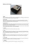
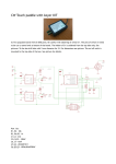
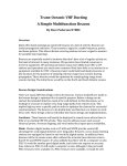
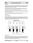
1
PicoKeyer-Plus
Ultra Low Power Morse Memory Keyer
The PicoKeyer is a single chip, automatic iambic Morse code memory keyer. Its small size, low
power requirements and robust set of features make it perfect for portable or QRP operation or for
integrating into transmitters or transceivers.
Features of the PicoKeyer-Plus:
Dual MOSFET keying circuit will key
transmitters up to 60 V, positive or negative
Simple one-button "menu" interface
Four 60-character message memories can
be chained together for longer messages
Works with any dual lever iambic paddle,
single lever keyer paddle or straight key
Dot and dash memories, automatic timing
and element spacing
Setup and message entry using your paddle
Auto straight key detect, all message
memories available with straight key
―Bug‖ mode allows automatic dots with
manually formed dashes
Speed adjustable from 5 to 60 WPM via
menu OR speed control potentiometer
Speed control can be set to your preferred
speed range
Dual-Set Speed allows quick QRS/QRQ
and return to favorite speed
Adjustable weight
Variable pitch audio sidetone
Curtis ―A‖ or ―B‖, ―bug‖ and Ultimatic
keying modes
PicoKeyer-Plus
Variable letter spacing
Tune mode with on/off carrier or automatic
string if dits for easy tuneup
Beacon mode with adjustable 0 – 99 second
repeat delay and optional power-on auto start
MCW mode for sending audio Morse over
voice radios
Memory ―pause‖ command with automatic
resume allows manual insertion of RST etc.
into message
Auto-incrementing QSO / serial number can be
embedded in memory messages, with or
without leading zeros
Paddle switching - select left or right handed
operation
Variable transmitter QSK delay compensation
Memory and parameter settings retained with
power off
Low voltage - from as low as 2.5 to 5.5V
Low current - typically under 1 mA when
keying, with automatic extreme low power
sleep mode.
All controls and connectors on board
09/06/2012 (Firmware V4.1)
Page 1 of 17
Operating the PicoKeyer-Plus:
Once your PicoKeyer-Plus is assembled, mounted in the cabinet and has the battery installed, it’s time to connect your paddles
and transmitter or transceiver and take a little time to read this manual to learn how to use your PicoKeyer’s features.
This is the connections end of your PicoKeyer. The left
hand jack is for your paddles (input); the right hand jack is
for your transmitter or transceiver (output).
This is the controls end of your PicoKeyer. The speed
control knob is on the right, the memory/setup pushbutton is
on the left.
The Speed Control
This is the control you will probably use the most often. The code speed can be adjusted from 5 to 40 words per minute
(WPM) by simply turning the speed control knob. You may notice that the speed will decrease to 5 WPM as you rotate the
knob counter-clockwise, then suddenly jump to 13 WPM. This is a special feature known as ―Dual-Set Speed‖.
Two Morse code speed settings are available for your use. The current speed is the speed at which the keyer is operating,
regardless of whether that speed is derived from the speed pot or the menu. The stored speed is saved in the chip’s internal
non-volatile memory, and is used when the speed pot is turned to its minimum position. At any time you may use the speed
adjustment to set any speed from the low range setting to the high range setting. Setting the speed with the pot does not affect
the stored speed, which will always be available by simply turning the pot to its full counter-clockwise position. This feature
can be very useful; for example, you can keep your speed set at a constant, favorite speed, but have the option of rapid
QRS/QRQ to answer faster or slower stations. Or, you can simply ignore the stored speed and always use the pot for speed
control – it’s up to you.
One thing to note: you can set the stored speed anywhere from 5 to 63 WPM – and it doesn’t have to be within your pot speed
control range. You can also set the range of the speed control to whatever is best for you. See the Range (RL & RH)
commands in the ―Setup Menu Commands‖ section.
The Pushbutton
One pushbutton switch is used for memory messages and setup. Exactly how this works will be different depending on
whether you are using a straight key or a paddle, and your preferences. We’ll cover the default settings first, then discuss some
variations.
Pressing and immediately releasing the button once (a ―tap‖ of the button) will send the message stored in Message 1 (M1), if
there is one stored. You can also use the paddle inputs to quickly send messages M2, M3 and M4.
To send M2: Briefly press the button while you tap the DOT paddle.
To send M3: Briefly press the button while you tap the DASH paddle.
To send M4: Briefly press the button while you tap BOTH paddles together.
Pressing and holding in the pushbutton more than about half a second will also allow you to send messages M2, M3 and M4.
If you wish to send the contents of message memory 2 (M2), release the button when you hear two dits, sent via the sidetone
only. Similarly, to send message 3 or 4 (M3 or M4), hold in the button until you hear three or four dits, then release. This is
useful for sending messages while using a straight key.
To enter setup mode, continue to hold the button down until you hear the keyer’s command prompt, a Morse question mark ―?‖
character. This tells you that the keyer is waiting for your input. In setup mode, you will normally just send the letter of the
PicoKeyer-Plus
09/06/2012 (Firmware V4.1)
Page 2 of 17
setting you want to check or change – for example, S to set the stored speed. That will let you make changes to a setting until
you tap the button to return to command mode. Each time you return to command mode, you will hear the ―?‖ prompt.
BUT – this method won’t work with a straight key, since the PicoKeyer can’t copy your commands from a straight key – only
from paddles. If you are using a straight key, the keyer will revert to Button command mode. In this mode, you simply hold
the button and listen to the keyer send the letters for each menu setting, one by one. When you hear the one you want to check
or set, just release the button. If you don’t want to carry a ―cheat sheet‖ with the commands listed and can’t remember them,
you can also set Paddle Command Mode to use this mode for setup all the time (see setup menu item ―C‖).
Power control
Note that your PicoKeyer does not have a power switch! The microprocessor ―brain‖ of the keyer will go into a low-current
sleep mode after about ½ second with no inputs from either paddle. In sleep mode, the keyer chip draws so little current that
the internal battery can last for years. As soon as you touch a paddle, the chip instantly ―wakes up‖ and continues its normal
operation. At this point the keyer will operate as a normal iambic keyer, sending dots and dashes with automatic spacing and
timing according to paddle inputs and stored settings.
Replacing the Battery
The battery in your PicoKeyer-Plus should last for a long time – anywhere from several months to several years. Battery life
depends on a few factors:
Frequency of use. Obviously, the more you use the keyer, the shorter the battery life will be.
Sidetone. The sidetone speaker draws more power than the rest of the keyer. Using the sidetone speaker will reduce
battery life – but you should still only have to replace it once in a great while.
Straight key use. Leaving a straight key plugged in while not using the keyer will drain the battery within a few
weeks. If you use a straight key, unplug it when you’re not operating.
Beacon mode. The keyer does not sleep between messages while in beacon mode. If you use your PicoKeyer to
control a beacon full time, you should use an external power source. This can be as simple as a pair of series AA or
AAA alkaline cells, or you can use the kit’s Zener diode and resistor for power sources up to about 20 Volts DC.
Battery replacement is straightforward – just remove the two screws from the cabinet bottom, open the cabinet and pop the
coin cell battery out of its holder. Hold the setup button in for a couple of seconds to make sure power is completely drained,
then release the button and install the new battery. All of your settings and messages will be retained even with no battery
power.
If you should need to replace the battery in your keyer, you will need a CR2032 or equivalent lithium cell. These are very
common and are used in many devices from garage door openers to car remotes to thermometers and medical monitors. You
can order high quality CR2032 cells from www.HamGadgets.com.
Master Reset
In case you happen to get the settings to a point where the keyer is unusable, you can easily return your PicoKeyer to its default
settings. Open the case and remove the CR2032 coin cell from its holder. Push the setup button with the battery removed –
this is to ensure that power is completely removed from the chip. Now, hold the button in while you insert the battery into its
holder. At this point the keyer will send ―RESET?‖; tap either paddle to perform a complete reset. If you don’t want to do
that, just tap the button again to exit.
Straight Key Mode
The PicoKeyer can automatically detect and use a properly wired straight key if one is plugged in when power is applied.
During its power-on program, the PicoKeyer checks to see if either paddle input is grounded. If one input is shorted, the other
input is assumed to be a straight key. This way you can plug in a straight key wired to a mono plug and use it without any
changes or adjustments. Be aware that while the menu will still function, many parameters will not be adjustable (and would
not apply to a straight key anyway). You will not be able to record messages while using a straight key. If your PicoKeyer is
in the plastic cabinet, you may find it more convenient to switch between paddles and a straight key using the K menu setting.
PicoKeyer-Plus
09/06/2012 (Firmware V4.1)
Page 3 of 17
Sidetone
The PicoKeyer’s sidetone is a square wave audio signal generated by the microprocessor. Sidetone can be turned on or off,
and the audio frequency can be changed from the setup menu. There is a very noticeable peak in the response of the on-board
speaker at roughly 2 kHz; if your PicoKeyer is installed in the plastic cabinet you’ll probably want to find this peak so you can
hear it with the case assembled. The default setting should be at this audio peak.
Keying the transmitter
The PicoKeyer will key any solid state, tube or hybrid transmitter or transceivers that uses a keying voltage of 60V or less,
positive or negative. If you are using the keyer with a negative keyed transmitter, you will need to make sure the KEY and
RIG jacks are isolated from each other – this is the case when the keyer is mounted in its plastic cabinet.
If you intend to use the PicoKeyer with a rig requiring grid-block or cathode keying voltages over 60 V, you will need to use a
separate high voltage keying adapter. The Universal Keying Adapter 3 available from NØXAS at www.hamgadgets.com is
optically isolated and will handle solid-state, grid-block or cathode keyed transmitters at up to 400 V. Of course, you can
always build your own!
Keying Modes (What’s Mode A, Mode B and Ultimatic??)
There have been a couple of different operating modes for iambic keying that have evolved over the years. Modes
A & B are simply a matter of when the keyer checks for input from the paddles. In iambic mode A, the keyer only
checks for paddle inputs after the end of each dot or dash. In iambic mode B, on the other hand, the keyer will
check for paddle input during each dot or dash.
In practice, this can mean that you get ―extra‖ or ―dropped‖ dots or dashes at the end of a character, depending on
how you send. If you find that the keyer often drops the last dot or dash in a character, or you often get an extra dot
or dash at the end of a character, try switching between modes A & B and see which one best suits you. I find that
Mode B worked best for me when using a single-lever paddle, while Mode A works best with a dual-lever paddle.
Ultimatic mode is a different way of handling iambic keying. In modes A & B, if the keyer sees both paddles
closed it will alternate sending dots and dashes. Ultimatic, on the other hand, will send dots or dashes according to
the last paddle to be pressed. For example, to send the letter P in mode A or B, you would close the dot paddle,
then close the dash paddle and release the dot paddle for the two dashes, then release the dash paddle and close the
dot paddle for the last dot. In Ultimatic mode, you would close the dot paddle and hold it closed, close the dash
paddle for the two dashes, then release it for the last dot. Some letters are easier to send and require less effort
using Ultimatic mode. It’s a little bit of an adjustment from regular iambic keying; it took me a couple of hours of
practice to get used to it.
Selecting a keying mode (A, B or Ultimatic) is largely a matter of personal preference. There is no one ―right‖ way
that works for everyone; find which works best for you.
Using Your Keyer With a Handheld or FM Rig (“MCW” Mode)
One of the unique features of your PicoKeyer-Plus is MCW mode (menu option ―T‖ for sidetone, select ―M‖ for
MCW). In this mode, the keying output can be used to trigger the PTT input of a VHF or UHF handie-talkie or FM
mobile rig, allowing you to use your FM rig for Morse code. This is not CW (Continuous Wave) operation, nor is
it true MCW (Modulated CW) mode – it’s really just an FM transmission, with audio Morse code tones sent instead
of voice. This makes it easy, for example, to have a CW practice net using a local repeater – with the blessing of
the repeater operator, of course – or a simplex frequency. Those participating don’t need HF privileges or HF
equipment to learn and practice Morse code on the air.
PicoKeyer-Plus
09/06/2012 (Firmware V4.1)
Page 4 of 17
It is not possible to give detailed instructions for attaching your keyer to every rig on the market. You will need to
take a look at your rig’s manual to determine how the audio and PTT signals from the keyer need to be connected.
Doing it wrong could possibly damage your rig and/or your keyer! However, presented here are a few examples
that you may find useful for setting up your station for FM code practice. Refer to the operator’s manual for your
rig for specific requirements for PTT and audio.
Using MCW mode requires making soldered connections to a set of solder pads (JP1), which is located underneath
the battery holder on the PicoKeyer’s printed circuit board. You can ―tack solder‖ wires in place using a low
wattage pencil type iron, 25-35 Watts maximum. Be sure to remove the battery before soldering.
In Figure 1, we see the most common method that will work with
many handheld transceivers from Alinco, Yaesu, Icom and others
that use a similar combined audio/PTT scheme. This value of the
capacitor is not critical, and can be several times smaller or larger. A
2.2K or 2.7K Ohm resistor is used in series with the PTT line to key
the rig. In most cases, GROUND is connected to the sleeve (barrel)
of a 2.5mm stereo plug, and PTT/Audio is connected to the tip – but
again, be sure to consult your rig’s manual.
Figure 1 - Keying Yaesu and similar HTs
Figure 2 shows the method for using with with separate audio and
PTT lines. Consult your rig’s manual for the correct plug and wiring
to use.
Figure 2 - Keying HTs with separate audio & PTT
The diagram in Figure 3 illustrates the method used by some
Icom handhelds. If your HT does not respond with the circuit
in Figure 1, try this one instead.
Figure 3 - Keying ICOM and similar HTs
Figure 4 shows the method used with mobile or fixed station rigs.
You will likely find it easiest to connect the keyer via the packet data
connector. The schematic shows an optional audio level control
potentiometer that may or may not be needed.
Figure 4 - Keying FM mobile rigs
PicoKeyer-Plus
09/06/2012 (Firmware V4.1)
Page 5 of 17
About Setup Mode
In setup mode, all except the U, M, V and F commands share a common method of reviewing and changing the
current setting. In general:
Send the letter corresponding to the setting you want (M, S, etc). In ―Button‖ command mode, hold the
button until you hear the letter of the item you want to review or change, then release it.
The keyer will respond with the current setting.
For most commands, simply use the dot or dash paddle to change the setting. Tapping either paddle will
step through the possible settings. The dash paddle ―steps up‖ , the dot paddle ―steps down‖.
Tap the setup button to return to the ―?‖ command prompt (―Paddle‖ command mode). In ―Button‖
command mode, a short tap of the button will exit setup mode, while holding it will advance to the next
setting.
There are some exceptions to this rule. The specifics for the U, M, V and F commands are detailed below.
PicoKeyer Setup Menu Commands
U
Tune mode: Tune mode is used to send either a steady carrier or a series of dits for adjusting or testing
your station equipment. While in tune mode, each paddle acts as an on/off toggle switch. Tap the dash
paddle to turn a steady carrier on or off. Tap the dot paddle to start or stop a continuous stream of dits.
This is gives you a 50% duty cycle signal that is preferred by some operators as a way to tune up with
less stress on final PA, tuner and antenna components.
S
Speed: The keyer will always announce the current speed in WPM. If the current speed is not the same
as the stored speed, the keyer will announce the current speed followed by a slash and the stored speed.
For example: Assume the stored speed is 13 WPM, any you have the optional speed pot installed and set
for 20 WPM. The keyer will announce ―20/13‖. If you have the pot set to its minimum, you will be
using the stored speed and the keyer will only announce the stored speed, since it is the same as the
current speed. It sounds more complicated than it is; play with it a little and you’ll get the hang of it.
(Default:
13 WPM)
You can adjust the stored speed from the menu. Tapping the dot paddle will decrease the speed by one
WPM, or the dash paddle will increase it. Holding either paddle will continuously increase or decrease
the speed, with a dot or dash sent at the new speed for each step. When the paddle is released, the keyer
will again announce the current speed setting and the stored speed, if it is different from the current
speed. Speed may be set from 5 to 60 WPM.
M
Messages: Four message memories are available, numbered 1 through 4. When you enter Message
mode, message 1 will be the default selection. You have a choice of actions available to you when in
memory mode, selected by sending a single character from your paddle:
Send the number 1, 2, 3 or 4 to select a message memory. The keyer will respond by sending 1,
2, 3 or 4 to confirm.
Send P (Play) to listen to the contents of the currently selected memory. The keyer will play the
message, followed by the Morse prosign AR and the message number.
Send R (Record) to record a new message. If a message already exists it will be erased and
replaced. The keyer will respond with K to let you know it is in record mode. Enter your
message, with exaggerated word space but normal spacing between characters. If you make a
mistake when recording the message, just send 8 dits and the keyer will backspace one word.
You will hear a single dit to confirm this (two dits means you are at the beginning of the
message). Tap the setup button once when you are finished recording. The keyer will send R
and the message number to indicate the end of the message. You can then Play the message
back.
Send C (Continue) to add to or edit the message. The keyer will play the current message, then
PicoKeyer-Plus
09/06/2012 (Firmware V4.1)
Page 6 of 17
enter Record mode. You can backspace over existing words if needed.
You can use the R, P and C commands to listen and change your message until you're satisfied. Each
memory can hold up to 60 characters. If you send something other than 1 - 4, P, R, or C the keyer will
respond with ―?‖ and let you try it again.
Several special embedded commands may be used in messages. All commands start with a slash
followed by one or two characters. When playing back a message in setup mode you will hear the
command itself, not its effect – message chaining, QSO numbers, pause and beacon mode are inactive
while in setup mode. For example, you will hear /R instead of the word to be repeated. To store a slash
character in a message, save it as //.
/R will repeat the last word, including the word space after it. This can save a lot of memory space,
since each /R takes up only two character positions in memory. For example, to send a 3x3 CQ, you
can simply store ―CQ /R/RDE (callsign) /R/RK‖. This can save a lot of memory space.
/1, /2, /3 and /4 can be used to chain the message memories. The indicated message will be played
immediately when one of these commands is encountered. You can chain messages in any order.
/P will insert a pause in the message. This will cause the message to pause while you manually send
information such as manually entered QSO number, RST, etc. The message will automatically
resume after a full word space has passed with no paddle input. Hint: If you use /P, store it
immediately following the preceding characters without a word space. In other words, store ―UR
RST/P …‖ instead of ―UR RST /P …‖. This prevents you starting to send before the word space
completes, which will terminate memory playback completely.
To have your message automatically repeat at timed intervals, insert the command /B (BEACON) at
the end of your message. This will cause the keyer to delay for the number of seconds set with the B
parameter (see below) and re-send the message. You can terminate beacon operation by tapping
either paddle or the button. This can be especially useful for calling CQ, or to use your PicoKeyer to
control a propagation beacon or ―fox‖ transmitter.
To have Message #1 automatically start whenever power is applied to the PicoKeyer, store the /A
command as the first two characters in message #1. This is useful for autostarting a keyer used as
part of a beacon. Remember that you will still need to use /B at the end of the message if you want it
to repeat.
To send the QSO number and increment it by one, send /QI (QSO & Increment).
To send the QSO number and NOT increment it, send /QN (QSO & No increment).
To the last (previous) QSO number, send /QR (QSO Repeat). This is useful during contests if you
need to send a ―fill‖.
To temporarily increase the keyer speed by one WPM, send /SU (Speed Up). Note that this and the
/SD command will take effect immediately and will remain in effect only until the message is
finished. You can store multiple /SU or /SD commands to change speed by more than one WPM –
for example, /SU/SU will increase your speed by 2 WPM.
To temporarily decrease keyer speed by one WPM, send /SD (Speed Down).
To temporarily set a specific speed, send /Snn where nn is the speed you want. /S or /S0 will resume
the normal speed. For example, to send a signal report at 30 WPM and return to the normal speed
you would use /S30 599/S.
To alter the letter spacing, send /Fn where n is one digit, 0 through 9. This will act the same as
setting the letter spacing in the menu. For example, say you want to add a little extra space between
letters in your call sign in a CW message. You could store, ―CQ /R/R DE /F2N0XAS /R/R K
/F0/B‖. Remember to set the letter spacing back to your normal setting.
To insert an extra word space in your message, use the special prosign character ―1M‖ (.------).
To insert a steady carrier, use the /Cn command, where n is the number of seconds (from 1 to 9) that
you wish to send the carrier.
PicoKeyer-Plus
09/06/2012 (Firmware V4.1)
Page 7 of 17
Q
QSO Number: The keyer will send the current QSO number. You can use the paddles to set the QSO
number anywhere from 1 to 255. Note that when the QSO number is auto-incrementing, it can go from 1
to 65535.
RL
Range Low: This sets the low end of the speed control pot range. The setting is adjusted the same way
you would set the stored speed – the dot paddle will reduce the setting, the dash paddle will increase it.
(Default: 5
WPM)
RH
(Default:
40 WPM)
L
(Default:
OFF)
X
(Default:
0/9)
Z
(Default:
N)
B
(Default:
15 sec.)
W
(Default:
5)
T
(Default:
Y)
K
(Default:
Mode A)
P
Range High: This sets the high end of the speed control pot range. Set the same way as the stored speed
and low range setting.
Auto letter spacing: The keyer will announce the current setting and wait for input. Automatic letter
spacing takes effect for messages sent from memory as well as code sent manually with the paddle.
0 turns automatic letter spacing off. In this mode you control the spacing between letters. This is
the default setting, and is the same as most keyers.
1 turns on auto letter spacing at the set speed. A letter space is automatically inserted if the keyer
detects no input from either paddle at the end of the space after a dot or dash.
Settings from 2 to 9 will set automatic letter spacing with longer delays. For example, selecting 2
will insert one extra ―dit‖ length spacing between characters. Selecting 3 will insert an extra 2
―dit‖ lengths, and so on.
Note that auto letter spacing is ignored while in setup mode.
Cut numbers: The keyer will send Ø and 9 using the current setting and wait. You can cycle between
no cut numbers (Ø 9) cut zeros (T 9), cut nines (Ø N), or both (T N). Note that this only affects the way
QSO numbers are sent. Other numbers in stored messages, or numbers sent by hand, are not affected.
The default setting is no cut numbers.
Leading Zeros: The keyer will send ―Y‖ or ―N‖ and wait. As with other menu settings, either paddle
may be used to switch between the two settings. Y will send numbers in stored messages with up to two
leading zeros (1 is sent as 001, 99 is sent as 099, 123 is sent as 123, 1000 is sent as 1000). N sends
numbers without leading zeros. Like the X setting, this affects only QSO numbers and not other numbers
stored in messages or sent manually. The default setting is N.
Beacon delay: The keyer sends the current beacon delay in seconds. Use the dash paddle to increase or
the dot paddle to decrease the delay between beacon transmissions from 0 to 99 seconds.
Weight: The keyer announces the current weight and waits for input. The dot paddle may be used to
decrease the weight or the dash paddle to increase it. Weight can be set anywhere from 1 (50% "light") to
5 (normal) to 9 (50% "heavy"). The default setting is 5.
Sidetone: The keyer announces the current sidetone setting and waits for input. You can use the dot and
dash paddles to switch between ―N‖ (sidetone OFF), ―Y‖ (sidetone ON) and ―M‖ (MCW mode). In
MCW mode, the keying output is active any time code is being sent and for two word spaces after the key
is released. This can be used to control the PTT line of an FM transmitter. Regardless of the sidetone
setting, the sidetone is always used while in setup mode.
Key Mode: The keyer will send the current keying mode: "A" or "B" for iambic A or B timing modes,
―U‖ for Ultimatic, ―G‖ for bug or ―S‖ for straight key. You can use the key or paddle to switch between
modes. In ―Bug‖ mode, dots are made automatically with the correct spacing and length with one paddle
input, while dashes are made manually with the other. If straight key mode is selected while using a
paddle, either paddle input will key the transmitter.
Paddle Selection: This will allow you to reverse the paddles for mis-wired paddles or left handed
operators. Simply hit whichever paddle you want to use for DITs. No need to rewire your paddle!
PicoKeyer-Plus
09/06/2012 (Firmware V4.1)
Page 8 of 17
A
(Default:
Around 2
kHz)
D
(Default:
0)
Audio Tone: The keyer will send a dash at the selected sidetone audio frequency each time a paddle is
hit. Use the paddles to increase or decrease the audio frequency as desired. The default setting is
approximately 2000 Hz, which gives the loudest audio from the on-board speaker.
Transmit delay compensation: Some transmitters tend to shorten Morse code elements when used in
QSK mode. This setting can be used to lengthen Morse elements and shorten spaces to compensate. The
setting can be from 0 to 50 milliseconds. This is similar to weighting, except that it is independent of
speed. Weighting shortens or lengthens elements by a percentage; delay lengthens elements by a
specified number of milliseconds. Be aware that this can cause problems when using large delays and
fast speeds. The default setting is zero.
V
Firmware version: The keyer sends the version number of its internal firmware program.
C
Command Mode: You can select between ―Button‖ mode (BTN) or ―Paddle‖ mode (PDL). In Paddle
mode, you will hear a ―?‖ prompt once you enter setup mode. Simply use your paddle to send the Morse
letter of the option you want to review or change. For example, to set the speed you would send ―S‖. To
leave a menu item, tap the button to return to the ―?‖ prompt. To leave setup mode, either tap the button
again or send ―SK‖ with your paddle.
(Default:
PDL)
In Button mode, just hold the button to scroll through the list of available commands. When you hear the
letter of the item you want to change, release the button. When you’re finished with that setting, you can
either tap the button to exit setup mode, or press and hold to continue with the list of setup commands.
Note: If you have selected Paddle mode but are using a straight key, the menu will temporarily revert to
Button mode since commands cannot be accepted from the straight key.
F
Factory Reset: The keyer sends ―RESET?‖ and waits. If you tap either paddle the keyer will be
completely reset to its original settings All message memories are deleted and the QSO number is reset to
1. If this is not what you want, tap the button to exit without making changes.
You can also perform a factory reset at power-on. The button is pressed when power is first applied, the
keyer will send ―RESET?‖ in Morse code. Tap either paddle to perform the reset, or press the button to
exit without resetting.
PicoKeyer-Plus
09/06/2012 (Firmware V4.1)
Page 9 of 17
Assembly Instructions
Before You Start
Your PicoKeyer-Plus kit was designed with the beginning kit builder in mind. With just a little care and practice,
even a first time kit builder can complete the project in a relatively short time. You will need to gather a few tools
and supplies together before beginning to assemble your kit. Here’s what you will need:
A clean, level, static-free work area with good lighting. Wooden workbenches are fine. If you are working
on a kitchen table, be sure to spread out some newspaper or something else to keep solder splatters and
sharp wire ends from damaging the table top.
A soldering iron. A small, low-wattage (25-35 Watt) pencil type iron is ideal. Avoid larger, pistol-grip
types. You can find inexpensive irons at your local Radio Shack. You will need a fine tip intended for
electronics. Be sure to use an iron rest or holder to keep the iron from damaging your work surface. If you
plan to assemble more kits, I recommend investing in a good quality, temperature controlled soldering
station such as the Weller WES or WLC series. You’ll be glad you did! Follow the iron manufacturer’s
instructions for tinning the tip, and keep a damp sponge handy to keep the tip clean.
Solder suitable for electronics work. Use a good quality, small diameter rosin core solder intended for
electronic assembly. DO NOT use acid core solder!
Small needle-nose pliers and a pair of small diagonal wire cutters. The smaller you have, the better off you
will be. Again, you can find hand tools intended for electronics work at Radio Shack and other suppliers
such as Techni-Tool, Jensen, Mouser and Sears.
A clamp or small vise to hold the work is a good idea. I use a PanaVise, but you can also construct a board
holder out of scrap wood and rubber bands. If you use a regular bench vise, use gentle pressure and
something to cushion the vise jaws.
A pencil to check off each step as you finish it.
Once you have all of your tools and supplies gathered together, you’re ready to get started. Warm up the iron while
you remove the parts from the bag and lay them out on the work surface. We’ll start with the small parts and work
our way through each component, checking them off on the list as we go.
To install a component such as a resistor or capacitor, follow these steps:
1. Hold or gently clamp the PCB with the component side up. The side with the white printing is called the
―component side‖ or top; the side with no white lettering is called the ―solder side‖ and is the bottom.
2. Bend the component wire leads, if necessary, to fit the spacing of the holes in the PCB. Insert the leads
through the holes in the PCB. From the bottom side of the PCB, bend the leads out at a 45-degree angle to
hold the part in place.
3. From the bottom of the PCB, solder the leads in place. Remember to place the tip of the iron at the point
where the lead comes through the PCB hole, so you heat the wire and the hole at the same time. Wait a
couple of seconds for the lead to heat up, then touch the solder to the lead and pad, NOT the soldering iron
tip. The solder should flow into the joint. Remove the solder and iron and don’t move the PCB for a
couple of seconds until the solder has cooled. The joint should be smooth and shiny. If it looks dull or
rough, touch the tip of the iron to the joint to re-melt the solder. If there is a blob of solder, use some solder
wick or a solder sucker to clean it up; re-solder the joint if needed.
Be careful not to leave the iron on the joint too long, and don’t use too much solder. Electronic
components and circuit boards can be damaged by too much heat for too long. If you have never soldered
electronic components before, it would be a good idea to find some scrap parts and PCB and practice on
them first. Also, it’s a great idea to find someone more experienced to help you learn this skill!
PicoKeyer-Plus
09/06/2012 (Firmware V4.1)
Page 10 of 17
4. Once the part is in place and the solder has cooled, use a pair of fine pointed cutters to trim the excess
component leads close to the PCB.
You can build your PicoKeyer-Plus kit to be powered by either the on-board coin cell battery or external DC
power. During normal use, the supplied battery should last at least a year or two. If you wish to use external
power, install the supplied Zener diode and resistor in Step 9 instead of the battery holder. Do not install both
power options! Connecting external power while a battery is installed can result in component damage and could
even cause the coin cell battery to heat up and explode or burn. If using external power, a source of 3-14 Volts DC
must be connected to JP1, not to the pads used for the battery holder.
Step-By-Step Assembly Instructions
Locate the printed circuit board (PCB). Orient the PCB with the
component side on top and the lettering right-side up as you look at
it.
Locate the three ceramic capacitors in your kit. These will be small
rectangular parts with two parallel leads. All of themare .01 μF
(marked 103). Install the three capacitors in the locations marked
C1, C2 and C3. The capacitors used in your kit are not polarity
sensitive (meaning, don’t worry – you can’t install them backwards).
Note: If you have an older version of the printed circuit board, C1
may be in a different location. The boards are functionally identical,
and the three capacitors still get installed in C1, C2 and C3.
Install one of the 2N7000 MOSFET transistors in location Q1. Make
sure the flat side of the transistor is facing the direction indicated by
the silkscreen printed outline. Leave about 1/8‖ between the circuit
board and the bottom of the transistor to avoid putting too much
stress on the leads.
Install the second 2N7000 MOSFET in location Q2, making sure the
flat side is oriented as shown on the printed outline. It’s not installed
the same as Q1!
PicoKeyer-Plus
09/06/2012 (Firmware V4.1)
Page 11 of 17
Now find the 8-pin IC socket. Orient the socket so that the notched
end is at the end indicated by the silkscreen markings. Insert the pins
into the PCB. You may need to bend the pins at any two diagonally
opposite corners flat against the bottom of the PCB to hold the
socket in place while you solder. Solder all eight pins in place. Be
careful not to use too much heat or too much solder.
Find the speaker and install it in the location marked SPKR. The
speaker may be marked with a + on one side; don’t worry about
polarity as it can be installed either way. Make sure the speaker is
inserted fully into the holes before soldering. Don’t bend the leads
of the speaker; you may want to use a bit of adhesive tape to hold it
in place. Don’t spend too much time soldering the speaker or it may
be damaged.
At this point, you have two options for powering your keyer. The included coin cell battery will power your kit for quite
a while, usually a couple of years or more under normal use. In some cases, however, you may wish to use an external
source of DC power instead. Examples would be if you plan to build your keyer into a transmitter or transceiver, or for
use as part of a beacon station that will transmit continuously. If you choose to use the on-board battery, install the
battery holder. For external power, leave the battery holder off and install the resistor and Zener diode instead. I
recommend using the battery unless you are building your PicoKeyer-Plus into another piece of equipment such as a
transmitter or transceiver. DO NOT use both external power and the battery – ever!
To use the on-board coin cell battery, locate and install the battery
holder. You may need to use a piece of adhesive tape to hold it in
place while you solder.
— OR —
If you wish to use external DC power, omit the battery holder.
Install 1K (Brn-Blk-Red) resistor R1 and Zener diode D1 instead.
The banded end of D1 should be toward the white circle marked on
the PCB. (Note: If you have an older circuit board, this resistor may
be marked R3. On those older boards, R1 is not used.)
PicoKeyer-Plus
09/06/2012 (Firmware V4.1)
Page 12 of 17
Install the speed control potentiometer in the location marked R2.
This must be inserted fully into the PCB so that the bottom of the
metal bracket is against the PCB. You may need to bend the sides
slightly inward to make it easier to fully seat. Turn the adjusting
shaft fully counter-clockwise.
Locate pushbutton switch S1. Install the switch in the location
marked S1.
Install the two stereo jacks in the locations indicated on the
component side of the PCB. Be sure to press them far enough in to
get them fully seated. There are three plastic ―bumps‖ on the bottom
that will fit into holes in the PCB when they are pushed all the way
in. Install the two threaded, knurled collars on the two stereo jacks.
This keeps them from getting lost! You can use them to mount your
PicoKeyer in a box or tin.
We’re almost there! Find the PicoKeyer chip and remove it from its
protective anti-static package foam. Locate the Pin 1 end – this end
will be marked with a molded notch and/or a dot. If you hold the
chip so you can read the markings on top, Pin 1 is toward your left.
Orientation is important here! Insert the chip into the socket so that
the notch and/or dot on the chip are on the same end as the notch in
the socket and the notch outline on the PCB.
PicoKeyer-Plus
09/06/2012 (Firmware V4.1)
Page 13 of 17
If you built your kit with the battery holder (recommended), locate
the battery and remove it from its protective packaging. Note that
the flat side is marked with a plus sign (+). This side will be up
when the battery is inserted into the battery holder. Insert the battery
into the battery holder. If you have done everything right, you
should hear the keyer send ―73‖ in Morse code through the speaker.
Congratulations! Your kit is complete. Note that resistor location
R1 is not used, and should be empty. So that’s not a missing part,
it’s really OK.
If you have the optional cabinet, now would be a good time to mount
your keyer in the cabinet. Make sure the speaker is underneath the
holes drilled in the top cover.
PicoKeyer-Plus
09/06/2012 (Firmware V4.1)
Page 14 of 17
Support Information
Warranty & Support
Your PicoKeyer is guaranteed against defects for one year from date of purchase. This warranty does not cover
damage due to improper modification, improper soldering or wiring, overvoltage, static damage or other misuse or
abuse. If you have problems, please contact me via email to arrange for an exchange or replacement part. If you
accidentally damage your keyer, don’t panic! Replacement parts are not expensive. Send an email and let me
know what you need.
Should you need support, have questions, have feature requests or bug/problem reports, please feel free to contact
me via email at [email protected]. I will make every effort to respond as quickly as possible.
Troubleshooting
Having problems during or after assembly of your kit? Don’t worry… it’s fixable! Here are some common
problems and what to do about them. More hints can be found at http://www.hamgadgets.com.
Q: Everything is done, but I get no “73” when I install the battery!
A: Almost all of these so far have turned out to be soldering mistakes. Remove the battery and check the voltage –
it should be just above 3 Volts. Now carefully go over the solder joints with a magnifying glass. Re-melt any that
look suspicious, and use de-soldering braid or a solder sucker to clean up any blobs you have left.
Q: I broke (or melted) a part! (Or, I got a bad part!)
A: Don’t panic. Email me, or just mail the bad part back to me with a note. Include your address! If you broke it,
it would be nice to include a buck or so to cover the postage. If it was bad when you got it, just say so. I’ll send a
replacement. I’m pretty easy to get along with.
Q: The sidetone audio is too low, I can’t hear it!
A: You can adjust the sidetone audio frequency (menu setting ―A‖); it will get quite a bit louder near the speaker’s
resonant frequency around 2 kHz. If that doesn’t do enough for you, you may want to use a small audio amplifier
and larger speaker. You might try covering the small hole in the top of the speaker with a piece of tape; this can
help, depending on the audio tone you are using.
Q: I’m having problems entering messages into memory.
A: The keyer will insert a word space if it sees more than about 1 "dit" time between characters. I allowed a little
play, but not a lot. I recommend that when storing the message, don't even try to worry about character spacing.
Let the keyer do it. Enter the characters as you normally would, but when you finish one character just start the
next immediately. You only need an instant after the last dit or dah when you're not touching the paddles. You
can't get the characters too close together even if you try unless you actually run them together, which would
happen if you start the second character before the first is complete.
A lot of people find it helpful to slow the keyer down when entering messages - if you normally work at 12 WPM,
slow it down to 8 or so, but enter the characters with almost no space between them. Let the keyer do the character
spacing. Just pause a second or two between words and let the keyer do the word spacing -- just like you can't get
the character spacing too close, you can't get the word spacing too large.
Q: I can’t enter a message into memory while using a bug or straight key.
A: Correct. You must be in iambic mode (A or B), and you need to use a paddle of some sort. Single or dual lever
is OK, but it must have separate dot and dash contacts. You may be able to save messages and use the menu while
PicoKeyer-Plus
09/06/2012 (Firmware V4.1)
Page 15 of 17
using a paddle in ―bug mode‖, but it’s tricky and I don’t recommend it. In any case, the recorded message will
have normal timing – not your ―bug fist‖.
Q: I removed and replaced the battery, and now the keyer doesn’t seem to work right.
A: The bypass capacitor on the board can store enough energy to power the keyer chip for several seconds.
Remove the battery, then press the setup button to discharge the filter caps. Now re-install the battery and you
should be OK.
Q: When I plug in a straight key, I just get dashes! How do I make it work with a straight key?
A: Straight key auto-detection works only during power-on. You need to remove the battery, plug in the straight
key, then insert the battery. It’s a good idea to press the setup button for a second or two while the battery is out, to
make sure the chip gets completely reset.
PicoKeyer-Plus
09/06/2012 (Firmware V4.1)
Page 16 of 17
Quick Reference & Connections
PicoKeyer Menu Quick Reference
2 dits (I)
3 dits (S)
4 dits (H)
U
S
Send M2
Send M3
Send M4
tUne mode
Speed
Z
B
W
T
K
M
Q
RL
RH
L
X
Memory
QSO# Set
Speed pot Range Lo
Speed pot Range Hi
Letter spacing 0-9
Cut numbers 0 / 9
P
A
D
V
C
F
Leading Zeros on/off
Beacon delay
Weight
Sidetone
Keying Mode (A, B,
Umatic, buG, Straight)
Paddle reverse
Audio tone
Xmit precomp. Delay
Firmware Version
Command mode
Factory Reset
Header JP1 Connections
JP1-1 Ground
JP1-2 DC power, 3-14V DC Only
JP1-3 Sidetone Audio
JP1-4 Pushbutton Switch
JP1-5 Keying (60V / 200 mA Max)
JP1-6 DOT paddle input
JP1-7 DASH paddle input
Schematic Diagram
PicoKeyer-Plus
09/06/2012 (Firmware V4.1)
Page 17 of 17