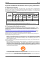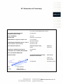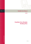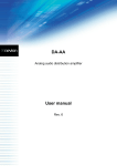
1
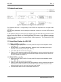
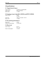
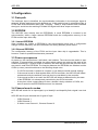
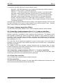
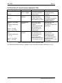
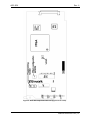
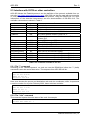
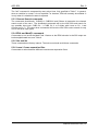
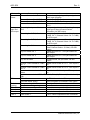
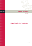
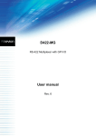
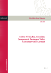
Flashlink User Manual
ADC-SDI
NTSC/PAL to SDI encoder
network-electronics.com
Rev. 6
ADC-SDI
Rev. 6
Network Electronics AS
P.O. Box 1020
N-3204 Sandefjord, Norway
Phone: +47 33 48 99 99
Fax: +47 33 48 99 98
Email: [email protected]
www.network-electronics.com
Support Phone: +47 90 60 99 99
Revision history
Current revision of this document is the uppermost in the table below.
Rev.
6
5
4
3
Repl.
5
4
3
2
Date
2008-07-14
2007-10-23
2007-10-09
2007-06-26
2
1
2005-07-07
1
0
2005-03-03
0
C
2004-01-20
C
B
A
B
A
-
2003-01-28
2002-02-07
2001-12-01
Sign
AS
AS
AS
TØ
Change description
Added Declaration of Conformity.
New front page.
Added Materials Declaration and EFUP
Corrected value for Return loss to ‘> 35 dB’ under
specifications. Applied new document template,
cleaned up document structure, added Appendix A
Materials declaration and recycling information.
New functionality added to DIP switch 9 (software
release ≥ 7).
Specification updated, and changed ConQuer to
Flashlink.
Updated with info about luma/chroma separation
filter.
Updated to ConQuer (software release 2).
Changed section numbering.
LED descriptions, and Flashlink commands.
Preliminary revision for PIC software revision 0.1.2
network-electronics.com | 2
ADC-SDI
Rev. 6
Contents
1 Product overview ..................................................................................................... 4
1.1 Quick Start Guides for ADC-SDI ........................................................................................4
2 Specifications .......................................................................................................... 5
2.1 Digital Serial Output ...........................................................................................................5
2.2 Analogue input, both PAL (625/50) and NTSC (525/60) ....................................................5
2.3 Processing performance ....................................................................................................5
2.4 Electrical.............................................................................................................................5
3 Configuration ........................................................................................................... 6
3.1 Data path............................................................................................................................6
3.2 EEPROM............................................................................................................................6
3.3 Power-up sequence ...........................................................................................................6
3.4 Channel search modes ......................................................................................................6
3.5 Luma / chroma separation filters ........................................................................................7
3.6 Selection of luma/chroma separation filter .........................................................................8
4 Connections............................................................................................................. 9
4.1 Mounting the connector module .........................................................................................9
4.2 Correspondence of connectors and signals .......................................................................9
5 Operation............................................................................................................... 11
5.1 Module status - Light Emitting Diodes..............................................................................11
5.2 Switches ...........................................................................................................................11
5.3 Interface with GYDA or other controllers..........................................................................14
General environmental requirements for Network Electronics equipment ................ 17
Product Warranty...................................................................................................... 18
Appendix A Materials declaration and recycling information..................................... 19
A.1 Materials declaration........................................................................................................19
A.2 Environmentally-friendly use period.................................................................................19
A.3 Recycling information.......................................................................................................20
EC Declaration of Conformity ................................................................................... 21
network-electronics.com | 3
ADC-SDI
Rev. 6
1 Product overview
Figure 1: Simplified block diagram of the ADC-SDI card
The Flashlink ADC-SDI is a high-quality 10-bit NTSC/PAL composite 4:2:2 to digital video
converter.
ADC-SDI user parameters can be changed via switches on the unit, or via the GYDA control
interface.
To aid digital to analogue conversion of the digital output the ADC-SDI may generate a white
pulse to mark first field of an 8-field-PAL/4-field-NTSC signal. If the digital to analogue
converter is able to detect this, it will synchronize to the correct field (8-field-PAL/4-fieldNTSC) when synchronizing to an external Black & Burst-generator. The Flashlink DAC-SDI
is able to do this.
1.1 Quick Start Guides for ADC-SDI
1.1.1 Without GYDA controller
1. Attach Analogue input (CVBS or S-Video) and SDI-output to the backplane module
(see Figure 2).
2. Set DIP-switch 1 on (towards backplane), switches 2 and 3 according to the Input
Channel search-mode you want (see Table 3).
3. Insert ADC-SDI into a slot in the sub-rack.
4. Power on. After some seconds the ADC-SDI should be running, and the input should
be detected. No LED should be red and the SDI output should be active. If this is not
the case, please see section 5.1.
1.1.2 With GYDA controller
1. Attach Analogue input (CVBS or S-Video) and SDI-output to the backplane module
(see Figure 2).
2. Insert ADC-SDI into a slot in the sub-rack.
3. Power on. After some seconds the ADC-SDI should be running, and the input should
be detected. No LED should be red and the SDI output should be active. The card
settings should be as the previous time power was applied.
4. Communication with the card is described in section 5.3.
network-electronics.com | 4
ADC-SDI
Rev. 6
2 Specifications
2.1 Digital Serial Output
Output format
270 Mb/s scrambled NRZI
Output level
800 mV nominal
Return loss
> 15 dB
2.2 Analogue input, both PAL (625/50) and NTSC (525/60)
Input formats
CVBS
S-Video
Input level
1000 mV nominal ± 10 mV
Return loss
> 35 dB
2.3 Processing performance
Signal path
10 bits
Video processing delay
2 video lines
2.4 Electrical
Input Voltage
DC 5 V
DC –15 V
Power Consumption
< 2.6 W
network-electronics.com | 5
ADC-SDI
Rev. 6
3 Configuration
3.1 Data path
The Analogue input is identified, the synchronization information in the analogue signal is
detected, and the analogue signal is digitized to a 10-bit parallel signal in a dedicated chip. A
FPGA adds EDH-information and Field 1 marking. Finally a chip serializes and scrambles
the signal, and drives the resulting 270 Mb/s SDI-signal onto three output connectors.
3.2 EEPROM
The ADC-SDI card actually has two EEPROM's. A small EEPROM is included in the
microcontroller, while a larger external EEPROM holds the configuration memory of the
FPGA and the input video chip.
3.2.1 Internal EEPROM
State variables are written to EEPROM in the microcontroller each time a configuration
change is made. Basically, the card remembers it's setting between power-downs.
3.2.2 External EEPROM
The configuration memory of the FPGA and the input video chip is upgradeable. This is,
however, a task for qualified maintenance personnel.
3.3 Power-up sequence
At power-up, the card performs a self-check, and initiation. The manual mode switch is then
sampled. If manual mode is enabled, the other switch settings are read and the state of the
card set accordingly. If manual mode is disabled, the state the card held the previous time it
was used is read from EEPROM. The interplay between the EEPROM, the switches and the
GYDA (or other) controller adheres to the following simple rules:
−
−
−
−
If a GYDA controller is present in a system, it can always override manual settings.
If the manual mode is used together with a GYDA controller, the ADC-SDI will initiate
as determined by the switches, and may then be overridden by the controller.
If the manual mode is not used, the ADC-SDI will initiate as determined by the state
of the EEPROM. It is subsequently controlled by the GYDA controller.
At any time, when a state change is done, whether it be by switches or GYDA, the
state is stored in the EEPROM as soon as it is detected.
3.4 Channel search modes
ADC-SDI will search for an input-signal, try to identify it and hopefully find a signal it can lock
to.
ADC-SDI has 2 input channels with 3 types of input:
−
−
−
CVBS Channel 1
CVBS Channel 2
S-Video: Luma Channel 1, Chroma Channel 2.
network-electronics.com | 6
ADC-SDI
Rev. 6
To search for input ADC-SDI has 4 channel search modes:
−
Automatic ADC-SDI searches for any possible input signal type. When a signal is
detected, it tries to lock to it, and stops searching.
− CVBS Ch. 1 ADC-SDI searches for CVBS input on channel 1, and ignores other
input types. When a signal is detected, it tries to lock to it, and stops searching.
− CVBS Ch. 2 ADC-SDI searches for CVBS input on channel 2, and ignores other
input types. When a signal is detected, it tries to lock to it, and stops searching.
− S-Video ADC-SDI searches for S-Video input, Luma on channel 1, chroma on
channel 2, and ignores other input types. When a signal is detected, it tries to lock to
it, and stops searching.
If the input type is changed while the card is running, or the signal is missing or lost, the card
will start searching for the type of signal defined by the channel search mode. Channel
search mode settings are described in sections 6 and 7.3.
3.5 Luma / chroma separation filters
The ADC-SDI module has 4 different luma / chroma separation filters to select between.
3.5.1 Comb filter - adaptive between 3-line (½, 0, ½) and no comb filter
This filter will adaptively select between 3-line (½, 0, ½) comb filter and no comb filter.
Adaptive comb filter is available for both luminance and chrominance. The adaptive comb
filter algorithm computes the vertical and horizontal contours of colour based on a block of
3x3 pixels. If there is a sharp colour transition, comb filtering is applied to the two lines that
have fewer colour changes. If there is no colour transition, 3-line comb filtering is used with
filter coefficients (½, 0, ½).
The comb filter can be selectively bypassed in luma or chroma path. If the comb filter is
bypassed in the luma path, then chroma trap filters are used which has a characteristic
according to CCIR601.
The adaptive comb filter algorithm reduces artefacts such as hanging dots at colour
boundary and detects and properly handles false colour in high frequency luminance images
such as a multi burst pattern or circle pattern.
3.5.2 Comb filter - adaptive between 3-line (¼, ½, ¼) and no comb filter
This filter will adaptively select between 3-line (¼, ½, ¼) comb filter and no comb filter, same
functionality as the above, but with different filter coefficients.
3.5.3 Fixed 2-line comb filter
This is a fixed 2-line comb filter with no adaptive selection.
3.5.4 No comb filter
This filter has no comb filter enabled. The luma signal will be filtered with a chroma trap, and
the chroma signal will be filtered with a low pass filter.
network-electronics.com | 7
ADC-SDI
Rev. 6
3.6 Selection of luma/chroma separation filter
Filter type
No comb filter
(filter 3)
Fixed 2-line comb filter
(filter 2)
Adaptive 3-line comb
filter
with filter coefficients
(½,0,½)
(filter 0 for PAL)
(filter 1 for NTSC)
Adaptive 3-line comb
filter
with filter coefficients
(¼, ½, ¼)
(filter 0 for NTSC)
(filter 1 for PAL)
Luma Bandwidth
Limitations
PAL ~= 4MHz
Limited bandwidth.
NTSC ~= 3MHz
Cross colour artefacts
visible in luma
Full bandwidth
Cross chroma errors at
available
vertical transitions.
For PAL: Some cross
colour artefacts in luma
Full bandwidth
available
Some cross colour
artefacts at vertical
transition.
Graphics material with
high saturation may
produce artefacts at
vertical edges.
Full bandwidth
available
Graphics material with
high saturation may
produce artefacts at
vertical edges.
Some Cross colour
artefacts visible in luma
for PAL signal sources.
Applications
VHS, Umatic and other
sources with lower
bandwidth
Full bandwidth
processing.
Not suitable for graphics
or material with high
saturation levels.
Best suited for PAL
signal sources.
Very good for most PAL
applications.
Best suited for NTSC
signal sources.
Very good for most
NTSC applications.
Also a good alternative
for PAL sources if
artefacts in (½, 0, ½) are
unacceptable.
Table 1: Selection of luma /chroma separation filter.
The factory default filter setting is: Adaptive 3-line comb filter with filter coefficients (½,0,½).
network-electronics.com | 8
ADC-SDI
Rev. 6
4 Connections
The ADC-SDI has its own connector module: ADC-SDI-C1, mounted at the rear of the subrack.
Figure 2: ADC-SDI-C1 connector module.
4.1 Mounting the connector module
If the connector module is purchased separately, it should be mounted as described in the
user manual for the sub-rack frame FR-2RU-10-2. This manual is also available from our
web site: http://www.network-electronics.com/
4.2 Correspondence of connectors and signals
The ADC-SDI-C1 connector module has 7 BNC's:
Ch1
Ch2
Dup1
Dup2
SDI1
SDI2
SDI3
Analog input: CVBS or S-Video Luma
Analog input: CVBS or S-Video Chroma
Passive loop through Ch1.
Passive loop through Ch2.
Digital SDI output
Digital SDI output
Digital SDI output
The analogue input BNC's can be used with CVBS, one at a time, or together with S-Video
Luma on Ch1 and Chroma on Ch2. SDI1, SDI2 and SDI3 are equivalent SDI outputs.
The backplane has a DIP-switch with two individual switches, as shown in Figure 2. Switch 1
is used to turn on/off 75 ohm termination on input channel 1, and switch 2 is used to turn
on/off 75 ohm termination on input channel 2.
The analogue input must be terminated somewhere to enable the video decoder
chip.
network-electronics.com | 9
ADC-SDI
Rev. 6
Figure 3: ADC-SDI simplified silkscreen (figure not to scale).
network-electronics.com | 10
ADC-SDI
Rev. 6
5 Operation
5.1 Module status - Light Emitting Diodes
Summary: Green LEDs are good, red LEDs are bad.
ADC-SDI implements four Light Emitting Diodes (LEDs) that show the state of the card. The
LEDs are visible through the front-panel of the rack (see the user manual of FR-2RU-10-2 for
details). The LEDs are described top-down, see also Figure 3.
5.1.1 Card State
No Light
Red
Yellow
Green
No power, fuse F1 blown, LED malfunction or configuration memory lost.
A fundamental, probably electrical, error has been detected. The card is set in a
passive state, so that it does not disturb other cards in the rack. While powering
on, the CardState LED will light red for approximately 0.5 s while the card
undergoes self-test.
The startup-sequence is running. The card is not yet ready
ADC-SDI is powered and ready.
5.1.2 State of input channel 1
No Light
Red
Yellow
Green
Channel 1 is inactive.
ADC-SDI tries to detect input signal on channel 1.
Input signal is detected on channel 1, but not yet locked.
Input signal on channel 1 is detected, and properly locked.
5.1.3 State of input channel 2
No Light
Red
Yellow
Green
Channel 2 is inactive.
ADC-SDI tries to detect input signal on channel 2.
Input signal is detected on channel 2, but not yet locked.
Input signal on channel 2 is detected, and properly locked.
5.1.4 SDI output
No Light
Red
Yellow
Green
Not used.
No SDI output, or SDI output not correct.
Not used.
Correct SDI output.
5.2 Switches
Summary: Most users will probably want switches 1, 6 and 10 in on position and
the rest in off position. All users should place switch 10 in the on position.
The ADC-SDI card implements a Dual-Inline switch (DIP-switch) that provides 10 individual
On/Off switches. The purpose of the switches is to offer you an easy interface to some
features of the ADC-SDI card, without the need of a GYDA controller. Table 2 gives the
general layout of the switches. The switches are numbered from '1' at the top and
downwards to the bottom, see Figure 3. A switch is on when the tap is displaced in direction
of the back-plane.
The ADC-SDI card is shipped with all switches, except switch 1, 6 and 10, in the Off-position.
Switch number 10 should always be in the On-position. The switches are discussed in logical
rather than numerical order.
network-electronics.com | 11
ADC-SDI
Switch #
1
2
3
4
5
6
7
8
9
10
Rev. 6
Function
Manual mode on/off
Input Channel select 1
Input Channel select 2
EDH disable on/off
Comment
When on, enables switches 2, 3, 4, and 5
According to Table 3
According to Table 3
When on, the EDH will not be inserted into the
SDI-output.
Mark Field 1 disable on/off
When on, the Mark Field 1-feature is not used.
Luma/chroma separation filters According to Table 4
Luma/chroma separation filters According to Table 4
Factory Reset on/off
To restore internal EEPROM only
Chroma blanking for Teletext
Chroma blanking for Teletext within vertical
blanking area
Running mode on/off
For factory use only
Table 2: Summary of the DIP switches. Switch 9 and 10 are mainly for factory use, while
switches 1, 2, 3, 4, 5, 6 and 7 will be used when no GYDA controller is available.
5.2.1 Switch 1 - Manual mode
Switch 1 is the manual mode switch. If set to on, the ADC-SDI is primarily assumed to be
operated with switches alone. If set to off, the ADC-SDI is assumed to be used with a GYDA
controller.
Factory setting is switch 1 in off position.
With switch 1 off
While in automatic mode, switches 2, 3, 4 and 5 are without any effect.
With switch 1 on
In manual mode, the functionality of switches 2, 3, 4 and 5 is as follows:
5.2.2 Switches 2 and 3
These two switches determine the input channel selection. See Table 4.
Factory setting is switch 2 and switch 3 off.
Sw #3
0
0
1
1
Sw #2
0
1
0
1
Input Channel Select
Automatic
CVBS Ch. 1
CVBS Ch. 2
S-Video
Comment
Search for any possible input type.
Only search for CVBS on Ch. 1
Only search for CVBS on Ch. 2
Only search for S-Video; Luma Ch. 1 and
Chroma Ch. 2
Table 3: Manual selection of video mode
5.2.3 Switch 4
Switch 4 turns on/off disabling of EDH in the output SDI. With switch 4 off, the EDH is
included in the SDI signal, with switch 4 on, EDH is not included.
Factory setting is switch 4 in off position.
5.2.4 Switch 5
Switch 5 turns on/off disabling of the Mark Field 1-feature. With switch 5 off the Mark Field 1feature is enabled, with switch 5 on the Mark Field 1-feature is disabled.
Factory setting is switch 5 in off position.
network-electronics.com | 12
ADC-SDI
Rev. 6
5.2.5 Switch 6 & 7
These two switches determine which Luma / Chroma separation filter that are in selected,
according to Table 5. The factory settings are switch 6 set to on and switch 7 set to off.
Function description
Switch #
6
7
0
0
1
0
0
1
1
1
Default adaptive 3-line comb filter selection.
NTSC adaptive comb with filter coefficients (¼, ½, ¼)
PAL adaptive comb with filter coefficients (½, 0, ½)
Adaptive 3-line comb filter selection with optional filter coefficients
NTSC adaptive comb with filter coefficients (½, 0, ½)
PAL adaptive comb with filter coefficients (¼, ½, ¼)
Fixed 2-line comb filter
No comb filter
Luma filtered with chroma trap
Chroma low pass filtered
Table 4: Luma / Chroma separation filter.
5.2.6 Switch 8 - Reset to factory default
ADC-SDI contains EEPROM that is affected by your choices. Switch 8 is implemented to
reset the EEPROM to factory default. Its use is shown in Table 5.
Action
Power down
Turn switch 8 on
Power up
Power down
Turn switch 8 off
Power up
Comment
ADC-SDI enters a special state where the EEPROM is restored to
factory default values. This is flagged by the LEDs, they are all yellow.
If you want the DIP switches to be placed in the factory default
position, this is the time to do so: Turn switches 1 through 9 to the off
position. Switch 10 should, as always, be turned to the on position.
The card EEPROM is now reset to factory settings.
Table 5: A method to restore the ADC-SDI card to the factory settings. Remember to let some
seconds pass by each time you power down, to allow capacitors to be fully discharged.
5.2.7 Switch 9 –Chroma Blanking for Teletext
Switch 9 is enabling Chroma Blanking within the vertical blanking area. When on, the chroma
information in lines 1-23 / 313-335 (PAL) or 1-21 / 263-284 (NTSC) will be erased (replaced
with 0x200). This is an important setting when using ADC-SDI with teletext information in line
23 (like for PAL+). When switch 9 is off, the vertical blanking area will be optimised for video
information.
When using ADC-SDI with S-Video (Y/C), it is recommended to leave switch 9 in off position
Factory setting is switch 9 in off position.
5.2.8 Switch 10 - Programming mode
Switch 10 is purely used for service upgrade of the ADC-SDI card. It should always be in the
on position. If switch 10 is in the off position, the CardState LED will light up red, and the
ADC-SDI card will enter programming mode. This causes no harm, but the card will not work
in this mode.
Factory setting is switch 10 in on position.
network-electronics.com | 13
ADC-SDI
Rev. 6
5.3 Interface with GYDA or other controllers
ADC-SDI follows the Flashlink-protocol, see the definition of the protocol available from our
web site: http://www.network-electronics.com/. ADC-SDI can also be used with any controller
or controller system that adheres to the Flashlink-protocol, using the RS422 bus. For more
information on the electrical interconnect, see the documentation of RS-2RU-10-2. The
available commands are shown in Table 6.
Command
?
info
AutoSearch
CVBSCh1
CVBSCh2
SVideo
EDH on
EDH off
MarkF1 on
MarkF1 off
get [0xHH]
set [0xHH] [0xHH]
filter 0
filter 1
filter 2
filter 3
Response
Yes
Yes
“OK”
“OK”
“OK”
“OK”
“OK”
“OK”
“OK”
“OK”
Yes
No
“OK”
“OK”
“OK”
“OK”
Comment
The “Hello” command.
Gives back the card state.
Set Cannel Search mode to automatic.
Set Cannel Search mode to CVBS Ch. 1.
Set Cannel Search mode to CVBS Ch. 2.
Set Cannel Search mode to S-Video; Luma Ch1,
Chroma Ch2.
Turn on EDH in output SDI.
Turn off EDH in output SDI.
Turn on the Mark Field 1-feature.
Turn off the Mark Field 1-feature.
Get a value from a numbered register.
Set a value to a numbered register.
Select luma/ chroma separation filter, see Table 4.
Select luma/ chroma separation filter, see Table 4.
Select luma/ chroma separation filter, see Table 4.
Select luma/ chroma separation filter, see Table 4.
Table 6: All commands available to the user
5.3.1 The '?' command
According to the Flashlink-protocol, no card can use the RS422-bus before the '?' (hello)
command is sent the card at least once. The response from ADC-SDI will be:
xxxxADC-SDI\
PIC sw rev X.X.X\
FPGA sw rev X\
Protocol ver X.X
Here xxxx denotes the source and destination rack and slot coordinates, while X represents
a version number. As of primo February 2002, these revisions would be:
xxxxADC-SDI\
PIC sw rev 1.1.0\
FPGA sw rev 7\
Protocol ver 1.0
5.3.2 The “info” command
This command reports the entire state of the card. An example:
xxxxChannel Select: automatic\
Locked PAL CVBS Ch. 1
network-electronics.com | 14
ADC-SDI
Rev. 6
The “info” command is composed by many minor lines, fully specified in Table 7. In general,
when a condition is normal, it is not reported. For instance, EDH will normally be enabled. It
is only when it is disabled its state is reported.
5.3.3 Channel Search commands
The commands AutoSearch, CVBSCh1, CVBSCh2 and SVideo all determine the channel
search mode of the card. The AutoSearch-command will let the ADC-SDI-card search for
any possible input type: CVBS Ch. 1, CVBS Ch. 2 or S-Video with Luma on Ch. 1 and
Chroma on Ch. 2. The other three commands will force the ADC-SDI-card to search for only
one of the three input types.
5.3.4 EDH- and MarkF1-commands
Commands to turn on/off the Mark Field 1-feature or the EDH inclusion in the SDI output are
both straightforward text, see Table 6.
5.3.5 Get and Set
These commands are factory internal. The end-user should avoid these commands.
5.3.6 Luma / Croma separation filter.
Commands to select between different luma/chroma separation filters.
network-electronics.com | 15
ADC-SDI
Status of
Channel
Select
Analog
input and
SDI output
EDH
Field 1
marking
Filter 0
Filter 1
Filter 2
Filter 3
Rev. 6
Status string
Channel Select: Automatic
Comment
Search for any legal type of input signal on
the 2 input channels.
Channel Select: Ch. 1 CVBS
Search for CVBS Ch. 1
Channel Select: Ch. 2 CVBS
Search for CVBS Ch. 2
Channel Select: S-Video
Search for S-Video, Luma Ch. 1, Chroma
Ch. 2
Searching for input on Ch1 and
No input signal detected. Searching for any
Ch2
legal type of input (Channel Select:
Automatic). No SDI output.
Searching for CVBS, Ch. 1
No input signal detected. Searching for
CVBS, Ch. 1 (Channel Select: Ch. 1 CVBS).
No SDI output.
Searching for CVBS, Ch. 2
No input signal detected. Searching for
CVBS, Ch. 2 (Channel Select: Ch. 2 CVBS).
No SDI output.
Searching for S-Video
No input signal detected. Searching for SVideo Channel Select: S-Video). No SDI
output.
Try lock CVBS Ch. 1
CVBS found on Ch. 1, not yet locked. No
SDI output.
Try lock CVBS Ch. 2
CVBS found on Ch. 2, not yet locked. No
SDI output.
Try lock S-Video
S-Video found, not yet locked. No SDI
output.
Locked <video standard> CVBS Stable locked CVBS on Ch. 1. SDI output is
Ch. 1
on.
Locked <video standard> CVBS Stable locked CVBS on Ch. 2. SDI output is
Ch. 2
on.
Locked <video standard> SStable locked S-Video input. SDI output is
Video
on.
Valid video standards: NTSC, NTSC 4.43, PAL, (M) PAL and (Combination-N)
PAL.
EDH off
No EDH information in SDI output.
(No EDH status string)
EDH information is included in SDI output.
Field 1 marking off
The Mark Field 1-feature is turned off
(No Field 1 marking-string)
Mark Field 1-feature is turned on
No filter status string
Luma / chroma separation filter 0 selected
Filter mode 1
Luma / chroma separation filter 1 selected
Filter mode 2
Luma / chroma separation filter 2 selected
Filter mode 3
Luma / chroma separation filter 3 selected
Table 7: The info command broken up in components.
network-electronics.com | 16
ADC-SDI
Rev. 6
General environmental requirements for Network Electronics
equipment
1.
2.
-
The equipment will meet the guaranteed performance specification under the following
environmental conditions:
Operating room temperature range: 0°C to 40°C
Operating relative humidity range:
Up to 90% (non-condensing)
The equipment will operate without damage under the following environmental
conditions:
Temperature range:
-10°C to 50°C
Relative humidity range:
Up to 95% (non-condensing)
network-electronics.com | 17
ADC-SDI
Rev. 6
Product Warranty
The warranty terms and conditions for the product(s) covered by this manual follow the
General Sales Conditions by Network Electronics AS. These conditions are available on the
company web site of Network Electronics AS:
www.network-electronics.com
network-electronics.com | 18
ADC-SDI
Rev. 6
Appendix A Materials declaration and recycling information
A.1 Materials declaration
For product sold into China after 1st March 2007, we comply with the “Administrative
Measure on the Control of Pollution by Electronic Information Products”. In the first stage of
this legislation, content of six hazardous materials has to be declared. The table below
shows the required information.
Toxic or hazardous substances and elements
組成名稱
Part Name
ADC-SDI
鉛
汞
镉
六价铬
多溴联苯
多溴二苯醚
Lead Mercury Cadmium Hexavalent Polybrominated Polybrominated
Chromium
biphenyls
diphenyl ethers
(Pb)
(Hg)
(Cd)
(Cr(VI))
(PBB)
(PBDE)
X
O
O
O
O
O
O: Indicates that this toxic or hazardous substance contained in all of the homogeneous materials for
this part is below the limit requirement in SJ/T11363-2006.
X: Indicates that this toxic or hazardous substance contained in at least one of the homogeneous
materials used for this part is above the limit requirement in SJ/T11363-2006.
A.2 Environmentally-friendly use period
The manual must include a statement of the “environmentally friendly use period”. This is
defined as the period of normal use before any hazardous material is released to the
environment. The guidance on how the EFUP is to be calculated is not finalised at the time
of writing. See
http://www.aeanet.org/GovernmentAffairs/qfLeOpAaZXaMxqGjSFbEidSdPNtpT.pdf for an
unofficial translation of the draft guidance. For our own products, Network Electronics has
chosen to use the 50 year figure recommended in this draft regulation.
Network Electronics suggests the following statement on An “Environmentally Friendly Use
Period” (EFUP) setting out normal use:
EFUP is the time the product can be used in normal service life without leaking the hazardous
materials. We expect the normal use environment to be in an equipment room at controlled
temperature range (0ºC - 40ºC) with moderate humidity (< 90%, non-condensing) and clean air, not
subject to vibration or shock.
Further, a statement on any hazardous material content, for instance, for a product that uses
some tin/lead solders:
Where a product contains potentially hazardous materials, this is indicated on the product by the
appropriate symbol containing the EFUP. The hazardous material content is limited to lead (Pb) in
some solders. This is extremely stable in normal use and the EFUP is taken as 50 years, by
comparison with the EFUP given for Digital Exchange/Switching Platform in equipment in Appendix A
of “General Rule of Environment-Friendly Use Period of Electronic Information Products”. This is
indicated by the product marking:
50
It is assumed that while the product is in normal use, any batteries associated with real-time clocks
or battery-backed RAM will be replaced at the regular intervals.
The EFUP relates only to the environmental impact of the product in normal use, it does not imply that the
product will continue to be supported for 50 years.
network-electronics.com | 19
ADC-SDI
Rev. 6
A.3 Recycling information
Network Electronics provides assistance to customers and recyclers through our web site
http://www.network-electronics.com. Please contact Network Electronics’ Customer Support
for assistance with recycling if this site does not show the information you require.
Where it is not possible to return the product to Network Electronics or its agents for
recycling, the following general information may be of assistance:
−
−
−
−
Before attempting disassembly, ensure the product is completely disconnected from
power and signal connections.
All major parts are marked or labelled to show their material content.
Depending on the date of manufacture, this product may contain lead in solder.
Some circuit boards may contain battery-backed memory devices.
network-electronics.com | 20
ADC-SDI
Rev. 6
EC Declaration of Conformity
MANUFACTURER
Network Electronics AS
P.B. 1020, N-3204 SANDEFJORD, Norway
AUTHORISED REPRESENTATIVE
(Established within the EEA)
Not applicable
MODEL NUMBER(S)
ADC-SDI
DESCRIPTION
NTSC/PAL to SDI encoder
DIRECTIVES this equipment complies with
LVD 73/23/EEC
EMC 2004/108/EEC
HARMONISED STANDARDS applied in order to
verify compliance with Directive(s)
EN 55103-1:1996
EN 55103-2:1996
TEST REPORTS ISSUED BY
Notified/Competent Body
Report no:
Nemko
E07379.00
TECHNICAL CONSTRUCTION FILE NO
Not applicable
YEAR WHICH THE CE-MARK WAS AFFIXED
2008
TEST AUTHORIZED SIGNATORY
MANUFACTURER
AUTHORISED REPRESENTATIVE
(Established within EEA)
Date of Issue
2008-07-14
Place of Issue
Not applicable
Name
Thomas Øhrbom
Position
Quality Manager
(authorised signature)
Sandefjord, Norway
network-electronics.com | 21