1
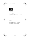
FS100 series
10/100Mbps Ethernet Switch
User’s Manual
Cod. MUUSW----FS10 Rev.7
Telsey Telecommunications
Copyright statement
This publication may not be reproduced as a whole or in part, any way whatsoever unless prior consent
has to be obtained from Telsey.
10/100Mbps ETHERNET SWITCH: FS124 and FS126
FCC warning
The 10/100 Ethernet Switch have been tested and found to comply with the limits for a Class A digital
device, pursuant to Part 15 of the FCC Rules. These standards have been designed to provide reasonable
protection against harmful interference when these devices are operated in commercial environment
These devices can use, generate and radiate radio frequency energy and may cause harmful interference
to radio communications unless installed in accordance with this User’s Guide. Operation of this device in
a residential area is likely to cause harmful interference which will make the user responsible for the
appropriate remedial action at his/her own expense.
CE mark Warning
These are Class A products. In a domestic environment these products may cause radio interference in
which case the user will need to consider adequate preventative measures.
-2-
Telsey Telecommunications
Electrical Safety and Emission Compliance Statement
The equipment complies with the following product specifications :
RFI Emissions : EN55022 Class A, FCC 47, Part 15, Class A;
Immunity : EN 55024 ; IEC61000-3-3; IEC61000-4-2; IEC61000-4-3;
IEC61000-4-4; IEC61000-4-5; IEC61000-4-6; IEC61000-4-11;
Safety : UNI EN 60825-1; UNI EN 60825-2, Class 1
UNI EN 60950 ; GOST R IEC 60950
The equipment complies with the following European Directives : 89/336/EEC (electromagnetic
compatibility), 73/23/EEC (low voltage), and 92/59/EEC (general product safety),
-3-
Telsey Telecommunications
Package Content : all models
Thank you for selecting and purchasing our product. Before you start installing the 10/100 Mbps Ethernet
Switch, check that the following items are in the package
•
10/100 Mbps switch
•
User’s Manual
•
Power Adapter
•
Rack Mount kit or Wall Mount kit (depending from the model)
The 10/100Mbps switch is the perfect way of integrating 10Mbps Ethernet and 100Mbps Fast Ethernet
devices. All five ports are auto speed negotiating, and have automatic MDI/MDI-X crossover detection,
so you don't have to worry about the cable type. Each port independently negotiates for best speed and
half- or full-duplex mode, for up to 200Mbps of bandwidth per port. Fast store-and-forward switching
prevents damaged packets from being passed on into the network.
-4-
Telsey Telecommunications
Port Speed
The twisted pair ports are compliant with the 10Base-T and 100Base-TX standards and are capable of
either 10 Mbps or 100 Mbps operation. The ports are IEEE 802.3u auto-negotiation compliant so the
switch will set the port speed automatically by the switch after it determines the speed of the end-node
connected to the port. Auto-negotiation is designed to ensure that the port on the switch and the
end-node are at the highest possible common speed of the devices.
Duplex mode
An end-node can operated in either half- or full-duplex mode depending on its capabilities.
The end-node that is operating in half-duplex mode can either send data or receive data, but it cannot do
both at the same time. Instead an end-node that is operating in full-duplex mode can send and receive
data simultaneously.
The twisted pair ports on the switch can operate in either half-duplex or full-duplex mode. The switch
sets the duplex mode automatically through auto-negotiation.
Auto MDI/MDI-X
An RJ-45 twisted pair port on a 10 Mbps or 100 Mbps Ethernet network device can have one of two
possible wiring configurations: MDI or MDI-X. A RJ-45 port on a PC, router, or bridge is typically wired as
-5-
Telsey Telecommunications
MDI, while a twisted pair port on a switch or hubs is usually MDI-X. To connect two 10 Mbps or 100 Mbps
network devices together that have dissimilar port wiring configurations, such as an MDI to MDI-X, you
would use a straight-through twisted pair cable. To connect two networks devices that have the same
wiring configuration, such as MDI to MDI, you would use a crossover cable.
The Switch features automatic MDI/MDI-X. The RJ-45 port automatically determines the configurations
of the port on the device to which it is connected and then configures itself appropriately.
MAC Address Table
The heart of an Ethernet switch is the Media Access Control (MAC) address table. Every device that you
attach to an Ethernet network has a MAC address. This address is assigned to the device by the device’s
manufacturer.
The switch creates the MAC address table by examining the frames that it receives on its ports. The
switch checks to determine whether the address is already in its MAC address table. If it is not, the switch
adds the address to the table along with the port number on which the frame was received.
The switch also checks the destination MAC address of each frame it receives. If the destination address
is not in the MAC address table, the switch broadcasts the frame to all switch ports.
The MAC address table in the switch can store and update periodically up to 2,000 MAC addresses.
-6-
Telsey Telecommunications
Installation
As with any electronic device, you should place the equipment out of extreme temperatures, humidity,
or electromagnetic interference. Specifically, the site you select should meet the following requirements:
•
If you are installing the Switch on a table, be sure that the table is level and secure;
•
If you are wall mounting the Switch, select a location on the wall that is safe and easily
accessible;
•
The power outlet for the Switch should located near the unit and should be easily accessible;
•
The site should provide easy access to the ports on the back and the power socket on the side
of the Switch. This arrangement will make it easy for you to connect and disconnect cables as
well as to view the LEDs;
•
To allow proper cooling of the Switch, air flow around the unit and through its vents should be
unrestricted;
•
Do not place objects on top of the chassis;
•
Do not expose the Switch to moisture or water;
•
Make sure that the site is a dust-free environment;
-7-
Telsey Telecommunications
•
Use dedicated power circuits or power conditioners to supply reliable electrical power to the
device.
Installation on a desktop
•
If you are installing the Switch on a table, be sure that the table is level and secure; attach the
four protective feet, if available, to the bottom on the unit. Do not attach the protective feet if
you are wall-mounting the switch.
Wall-Mounting Installation
The switch can be mounted horizontally on a wall using the keyholes on the bottom of the switch. The
screws, plastic anchors, and other materials necessary to mount the switch on a wall are not provided.
To wall-mount the switch, perform the following procedure:
z
If attached, remove the rubber feet, data cables, and power cord from the switch.
z
Select a wall location for the device.
z
Install two plastic anchors and two screws into the wall, separated by 85.34 millimeters.
Position the switch onto the wall screws so that the ports and LEDs are facing up.
To connect network devices to the Switch, follow these instructions:
-8-
Telsey Telecommunications
1. Make sure all the devices you will connect to the Switch are powered off.
2. Connect a Category 5 Ethernet network cable to one of the numbered ports on the Switch.
3. Connect the other end to a PC or other network devices.
4. Repeat steps 2 and 3 to connect additional devices.
5. Connect the supplied power adapter to the power port on the Switch’s back panel.
Note: Make sure you use the power adapter included with the Switch. Using a different
power adapter may result in damage to the Switch.
6. Plug the other end of the adapter into an electrical outlet.
7. Power on the devices connected to the Switch. Each active port’s corresponding LED will light up on
the Switch.
The description of Leds and ports is contained in the chapter dedicated to the specific switch model.
-9-
Telsey Telecommunications
1.
FS105, FS108: 10/100MBPS ETHERNET SWITCH
Features
•
5 port 10/100Mbps TX Auto-Negotiation Ethernet Switch (FS 105)
•
8 port 10/100Mbps TX Auto-Negotiation Ethernet Switch (FS 108)
•
Full/Half-Duplex capability on each TX port
•
Supports TP interface Auto MDIX function for auto TX/RX swap
•
Automatic Source MAC Address Learning and Aging
•
Supports up to 1024 MAC addresses
•
Up to 384KB buffer (FS 105)
•
Up to 768KB buffer (FS 108)
•
Supports Store & Forward architecture and performs forwarding and filtering
•
IEEE802.3x flow control for Full-duplex, Back Pressure for Half-duplex operation
•
Supports to handle up to 1536 bytes packet
•
LED indicators for simple diagnostics and management
•
Plug and Play
- 10 -
Telsey Telecommunications
FS105-FS108 FRONT Panel
- Power LED: This green indicator illuminates when the Switch is receiving power.
- Link/Act: This green indicator illuminates steadily when a port is connected to a station
successfully, if this green indicator is blinking, it indicates that a port is transmitting or receiving
data on the network.
- 10/100M: This green indicator illuminates steadily when a port is connected to a 100Mbps Fast
Ethernet station. Otherwise, the indicator is off when a port is connected to a 10Mbps Ethernet
Device.
FS105-FS108 BACK Panel
The network ports are located on the back panel of the switch. These ports are connection points
for PCs and other network devices, such as additional switches.
FS105-FS108
SIDE Panel
The Power port is located on the side of the switch. The power port is where you will connect the
included power adapter.
- 11 -
Telsey Telecommunications
Specifications
Physical (FS105)
Dimensions: 90mm(L) x 68.5mm(W) x 22mm(H)
Weight: 170 gr. (net)
Physical (FS108)
Dimensions: 140mm(L) x 77mm(W) x 28mm(H)
Weight: 300 g
Environmental
Maximum Operating: 0° to 40° C
Maximum Storage: -20° to 70° C
Humidity: 5% to 90 % non-condensing (operating), 5% to 90% non-condensing
(storage)
Operating and Storage Altitude: Up to 3000 meters
Power:
9Vdc – 500mA (max)
Standards:
IEEE 802.3 10Base-T, IEEE 802.3u 100Base-TX, IEEE 802.3x Flow Control
Certifications:
FCC Part 15 Class B, CE Mark, Gost Mark
Data Transfer Rate:
10/100Mbps (Half and Full duplex)
Access Method:
CSMA/CD
Network Media:
10BaseT: UTP Cat. 3 or higher, 100BaseTX: UTP Cat. 5 or higher
- 12 -
Telsey Telecommunications
Transmission Method:
Store and Forward
MAC Address Table:
2K for FS105, 1K for FS108
Built-in Buffe (FS105): 384K bits
Built-in Buffer(FS108): 768 KB
Auto MDI/MDIX:
2.
Yes
FS116: 16 PORT 10/100MBPS ETHERNET SWITCH
Features
•
16 port 10/100Mbps TX Auto-Negotiation Ethernet Switch
•
Full/Half-Duplex capability on each TX port
•
Supports TP interface Auto MDIX function for auto TX/RX swap
•
Automatic Source MAC Address Learning and Aging
•
Supports up to 4K MAC addresses
•
Up to 1,25MB buffer
•
Supports Store & Forward architecture and performs forwarding and filtering
- 13 -
Telsey Telecommunications
•
IEEE802.3x Flow Control for Full-duplex, Back Pressure for Half-duplex operation
•
Supports to handle up to 1552 bytes packet
•
LED indicators for simple diagnostics and management
•
Built-in power
•
Plug and Play
FS116 Front Panel LEDs
Power LED: This green indicator illuminates when the Switch is receiving power.
Link/Act: This green indicator illuminates steadily when a port is connected to a station
successfully, If this green indicator is blinking, it indicates that a port is transmitting or receiving
data on the network.
FDX/Col (Full-duplex/Collision): This green indicator is blinking when a port is transmitting or
receiving data at two operation mode, full duplex and half duplex.
1-16 Port: These ports are connection points for PCs and other network devices, such as additional
switches.
FS116 Back Panel LEDs
- 14 -
Telsey Telecommunications
The power connector is located on the back panel of the switch. AC Power Connector: This is a
three pronged connector that support the power cord. Plug in the female connector of the provided
power cord into this connector, and the male into a power outlet. Supported input voltages range
from 100~240V AC at 50~60Hz.
Specifications
Physical
Dimensions: 440mm(L) x 200mm(W) x 44mm(H)
Weight: 2,5 Kg
Environmental
Maximum Operating: 0° to 40°C
Maximum Storage: -20° to 70° C
Humidity:
5%
to
90
%
non-condensing
(operating),
non-condensing (storage)
Operating and Storage Altitude: Up to 3000 meters
Standards: IEEE 802.3 10BaseT, IEEE 802.3u 100BaseTX, IEEE 802.3x Flow Control
Certifications: FCC Part 15 Class B, CE Mark
Access Method: CSMA/CD
- 15 -
5%
to
90%
Telsey Telecommunications
Network Media: 10BaseT: UTP Cat. 3 or up, 100BaseTX: UTP Cat. 5 or up
Transmission Method: Store and Forward
MAC Address Table: 4K
Built-in Buffer: 1,25MB
Data Transfer Rate: 10/100Mbps (Half and Full duplex)
Auto MDI/MDIX: Yes
4.
FS124: 24 PORT 10/100MBPS ETHERNET SWITCH
Features
•
24 port 10/100Mbps TX Auto-Negotiation Ethernet Switch
•
Full/Half-Duplex capability on each TX port
•
Supports TP interface Auto MDIX function for auto TX/RX swap
•
Automatic Source MAC Address Learning and Aging
•
Supports up to 4K MAC addresses
•
Up to 1,25MB buffer
- 16 -
Telsey Telecommunications
•
Supports Store & Forward architecture and performs forwarding and filtering
•
Broadcast Storming Filter function
•
IEEE802.3x flow control for Full-duplex
•
Back Pressure function for Half-duplex operation
•
Supports to handle up to 1552 bytes packet
•
LED indicators for simple diagnostics and management
•
Plug and Play
FS124 Front Panel LEDs
Power LED: This green indicator illuminates when the Switch is receiving power.
Link/Act: This green indicator illuminates steadily when a port is connected to a station
successfully, if this green indicator is blinking, it indicates that a port is transmitting or receiving
data on the network.
FDX/Col (Full-duplex/Collision): This green indicator is blinking when a port is transmitting or
receiving data at two operation mode, full duplex and half duplex.
- 17 -
Telsey Telecommunications
1-24 Port: These ports are connection points for PCs and other network devices, such as additional
switches.
FS124 Back Panel LEDs
The power connector is located on the back panel of the switch. AC Power Connector: This a three
pronged connector that support the power cord. Plug in the female connector of the provided
power cord into this connector, and the male into a power outlet. Supported input voltages range
from 100~240V AC at 50~60Hz.
Specifications
Physical
Dimensions: 440mm(L) x 200mm(W) x 44mm(H)
Weight: 2,5 Kg
Environmental
Maximum Operating: 0° to 40° C
Maximum Storage: -20° to 70° C
Humidity:
5%
to
90
%
non-condensing (storage)
Operating and Storage Altitude: Up to 3000 meters
- 18 -
non-condensing
(operating),
5%
to
90%
Telsey Telecommunications
Power:
13.2W(max)
Standards: IEEE 802.3 10BaseT, IEEE 802.3u 100BaseTX, IEEE 802.3x Flow Control
Certifications: FCC Part 15 Class A, CE Mark
Access Method: CSMA/CD
Network Media: 10BaseT: UTP Cat. 3 or up, 100BaseTX: UTP Cat. 5 or up
Transmission Method: Store and Forward
MAC Address Table: 4K
Built-in Buffer: 1,25MB
Data Transfer Rate: 10/100Mbps (Half and Full duplex)
Auto MDI/MDIX: Yes
5.
FS126: 24 PORT 10/100MBPS ETHERNET SWITCH + 2 UPLINK 10/100/1000BASE-T
TWISTED PAIR PORT WITH 2 GBIC INTERFACES INTEGRATES
Features
•
24 port 10/100Mbps TX Auto-Negotiation Ethernet Switch + 2 Uplink 10/100/1000Base-T
- 19 -
Telsey Telecommunications
twisted pair port
•
Full/Half-Duplex capability on each TX port
•
Supports TP interface Auto MDIX function for auto TX/RX swap
•
Automatic Source MAC Address Learning and Aging
•
Supports up to 8K MAC addresses
•
Up to 1,25MB buffer
•
Supports Store & Forward architecture and performs forwarding and filtering
•
Broadcast Storming Filter function
•
IEEE802.3x flow control for Full-duplex
•
Back Pressure function for Half-duplex operation
•
Supports to handle up to 1552 bytes packet
•
LED indicators for simple diagnostics and management
•
Plug and Play
FS126 Front Panel LEDs
Power LED: This green indicator illuminates when the Switch is receiving power.
- 20 -
Telsey Telecommunications
Link/Act: This green indicator illuminates steadily when a port is connected to a station
successfully, If this green indicator is blinking, it indicates that a port is transmitting or receiving
data on the network.
FDX/Col (Full-duplex/Collision): This green indicator is blinking when a port is transmitting or
receiving data at two operation mode, full duplex and half duplex.
1-24 Port: These ports are connection points for PCs and other network devices, such as additional
switches.
FS126 Back Panel LEDs
The power connector is located on the back panel of the switch.
AC Power Connector: This a three
pronged connector that support the power cord. Plug in the female connector of the provided
power cord into this connector, and the male into a power outlet. Supported input voltages range
from 100~240V AC at 50~60Hz.
Specifications
Physical
Dimensions: 440mm(L) x 200mm(W) x 44mm(H)
Weight: 2,5 Kg
- 21 -
Telsey Telecommunications
Environmental
Maximum Operating: 0° to 40° C
Maximum Storage: -20° to 70° C
Humidity:
5%
to
90
%
non-condensing
(operating),
non-condensing (storage)
Power:
13.2W(max)
Operating and Storage Altitude: Up to 3000 meters
Standards: IEEE 802.3 10BaseT, IEEE 802.3u 100BaseTX, IEEE 802.3x Flow Control
Certifications: FCC Part 15 Class A, CE Mark
Access Method: CSMA/CD
Network Media: 10BaseT: UTP Cat. 3 or up, 100BaseTX: UTP Cat. 5 or up
Transmission Method: Store and Forward
MAC Address Table: 8K
Built-in Buffer: 1,25MB
Data Transfer Rate: 10/100Mbps (Half-duplex), 20/200Mbps (Full-duplex)
Auto MDI/MDIX: Yes
- 22 -
5%
to
90%
Telsey Telecommunications
TROUBLESHOOTING
Connectivity Testing
In the following procedure, you will test each port for a valid connection and to confirm the correct
operation of the network.
1.
Start with Ports 1 and 2. Connect these two ports of a single switch to two nodes or
workstations and turn on the switch power.
2.
Wait approximately 1-3 seconds for the auto-negotiation process to complete after power-on
or after the cables are reconnected.
3.
Make sure the Link/Activity and other LEDs of both switch ports are lit.
4.
After confirming that Port 1 and Port 2 are operational, reconnect one of the
nodes/workstations to another port, then repeat this connectivity test with the switch’s
remaining ports. Continue to verify the connection in each port by checking the Link/Activity
and other activity LEDs.
Problem Solving
If the POWER LED is OFF, do the following:
- Make sure that the power cord is securely connected to the wall outlet and the power connector is
securely connected to the back of the switch.
- Verify that the power outlet has power by connecting another device to it.
- Try using another power cord of the same type that came with your switch.
If a LINK/ACT LED is OFF, do the following:
- Check that the end-node connected to the port is powered ON and is operating properly.
- 23 -
Telsey Telecommunications
- Check that the twisted pair cable is securely connected to the port on the switch and to the port on the
end-node.
- Verify that the end-node connected to the port and the switch are operating at the same speed. Both
must be operating at either 10 Mbps or 100 Mbps.
- Make sure that the twisted pair cable does not exceed 100 meters (328 feet) and that you are using a
Category 3 or better cable for 10Base-T operation or a Category 5 or better cable for 100Base-TX
operation.
- Make sure that you are using an undamaged cable.
If there is a communication problem between the end-nodes connected to the switch, do the following:
- Verify that the end-nodes are operating with the same duplex mode.
RETURNING PRODUCTS
Products for return or repair shall be sent to an authorized repair centre. For support refer to the Telsey
web site.
Warranty Terms
Telsey guarantees the product to be free from defects in materials and workmanship at the date of original purchase
for a period of 24 MONTHS. If within the guarantee period the product is determined to be defective (at the date of
original purchase) due to improper materials or workmanship, Telsey will, without charge for labour or parts, repair or
(at Telsey's discretion) replace the product or its defective parts subject to the terms and limitations below. Telsey may
replace defective products or parts with new or refurbished products or parts. All products and parts replaced become
the property of Telsey.
- 24 -
Telsey Telecommunications
Guarantee services will be provided only if the original invoice or sales receipt (indicating the date of purchase, model
name and dealer's name) is presented with the defective product within the guarantee period. Telsey may refuse
free-of-charge guarantee service if these documents are not presented or if they are incomplete or illegible. This
Guarantee will not apply if the model name or serial number on the product has been altered, deleted, removed or
made illegible.
- This Guarantee does not cover transport costs and risks associated with transport of your product to and from Telsey.
- This guarantee does not cover:
a) periodic maintenance and repair or parts replacement due to wear and tear
b) consumables (components that are expected to require periodic replacement during the lifetime of a product)
c) damage or defects caused by use, operation or treatment of the product inconsistent with normal personal or
domestic use
d) damage or changes to the product as a result of : misuse, failure to install or use the product for its normal
purpose or in accordance with Telsey instructions on installation or use, failure to maintain the product in
accordance with Telsey instructions on proper maintenance, installation or use of the product in a manner
inconsistent with the technical or safety laws or standards in the country where it is installed or used, repair or
attempted repair by persons who are not Telsey members, adjustments or adaptations without Telsey’s prior
written consent, accidents, fire, liquids, chemicals, other substances, flooding, vibrations, excessive heat,
improper ventilation, power surges, excess or incorrect supply or input voltage, radiation, lighting, other external
forces and impacts.
- 25 -
Telsey Telecommunications
APPENDIX : ELECTRICAL, SAFETY AND EMISSION INFORMATION
Electrical Safety notices (for all products)
Warning: To prevent electric shock, do not remove the cover. No user-serviceable part inside.
This unit contains hazardous voltages and should only be opened by a trained and qualifies
technician. To avoid the possibility of electric shock, disconnect electric power to the product
before connecting or disconnecting the LAN cables. Power cord is used as a disconnection device. To
de-energize equipment, disconnect the power cord.
Warning: Do not work on equipment or cables during periods of lightning activity
Warning: Class 1 Equipment. This equipment must be earthed. The power plug must be
connected to a properly wired earth ground socket outlet. An improperly wired socket outlet
could place hazardous voltages on accessible metal parts.
Pluggable Equipment. The socket outlet shall be installed near the equipment and shall be easily
accessible.
Caution: Air vents must not be blocked and must have free access to the room ambient air for
cooling. To allow proper cooling of the Switch, make sure that the air flow around the unit and
through its heat sink cooling fins on the rear is not restricted.
- 26 -
Telsey Telecommunications
Warning: Operating Temperature. This product is designed for a maximum ambient temperature of 70°
degrees C.
Warning: As a safety precaution, install a circuit breaker with a minim value of 20 Amps
between the equipment and the power source. Always connect the wires to the LAN equipment
first before you connect the wires to the circuit breaker. Do not work with HOT feeds to avoid
the danger of physical injury from electrical shock. Always be sure that the circuit breaker is in the OFF
position before connecting the wires to the breaker.
Warning: Do not strip more than the recommended amount of wire. Stripping more than the
recommended amount can create a safety hazard by leaving exposed wire on the terminal
block after installation.
Warning: When installing this equipment, always ensure that the frame ground connection is
installed first and disconnected last. The power source for the Switch should be located near
the unit and should be easily accessible.
Warning: Check to see if there are any exposed copper strands coming from the installed wire.
When this installation is done correctly there should be no exposed copper wire strands
extending from the terminal block. Any exposed wiring can conduct harmful levels of
electricity to persons touching the wires.
Caution: Do not install in direct sunlight, or a damp or dusty place. Do not expose the Switch
to moisture or water.
Caution: If the Switch is installed indoors, make sure that the site is a dust-free environment.
The site should provide for easy access to the ports of the gateway device. This will make it
- 27 -
Telsey Telecommunications
easy for you to connect and disconnect cables, as well as view the LEDs.
Circuit Overloading: Consideration should be given to the connection of the equipment to the supply
circuit and the effect that overloading of circuits might have on overcurrent protection and supply wiring.
Appropriate consideration of equipment nameplate ratings should be used when addressing this concern.
Warning: For centralized AC power connection, install only in a restricted access area.
Warning: Mounting of the equipment in the rack should be such that a hazardous condition is not created
due to uneven mechanical loading.
Warning: Remove all metal jewelry, such rings and watches, before installing or removing a
line card from a powered-on chassis.
Use dedicated power circuits or power conditioners to supply reliable electrical power to the device.
Warning: The chassis may be heavy and awkward to lift. Telsey recommends that you get
assistance when mounting the chassis in an equipment rack.
Warning: This unit might have more than one power cord. To reduce the risk of electric shock,
disconnect all power cords before servicing the units.
Warning: Only trained and qualified personnel are allowed to install or to replace this equipment.
Warning: To reduce risk of fire use only 18 AWG or larger wires, that should be provided by the installer.
If installed in a closer or multi-unit rack assembly, the operating ambient temperature of the rack
- 28 -
Telsey Telecommunications
environment may be greater than the room ambient temperature. Therefore, consideration should be
given to installing the equipment in an environment compatible with the manufacturer’s maximum rated
ambient temperature (Tmra).
Caution: Installation of the equipment in a rack should be such that the amount of air flow required for
safe operation of the equipment is not compromised.
Warning: Reliable earthing of rack-mounted equipment should be maintained. Particular
attention should be given to supply connections other than direct connections to the branch circuits (e.g.,
use of power strips).
Telecommunications compliance notice
Warning: When using your Communication equipment, basic safety precautions should always
be followed to reduce the risk of fire, electronic shock, and injury to persons, including the following:
•
Do not use this products near water, for example, near a bathtub, washbowl, kitchen sink, or
laundry tub in a wet basement or near a swimming pool.
•
Avoid using a Communication equipment (other than a cordless type) during electrical storm.
There may be a remote risk of electric shock from lightning.
•
Do not use the Communication equipment to report a gas leak in the vicinity of the leak
Warning: To reduce the risk of fire, use only 26 AWG or larger telecommunication line cords.
- 29 -
Telsey Telecommunications
WEEE
DISPOSAL OF WASTE EQUIPMENT IN THE EUROPEAN
UNION
This symbol on the product or on its packaging indicates that this product must not be disposed of with
your other household waste. Instead, it is your responsibility to dispose of your waste equipment by
handing it over to a designated collection point for the recycling of waste electrical and electronic
equipment. The separate collection and recycling of your waste equipment at the time of disposal will
help to conserve natural resources and ensure that it is recycled in a manner that protects human health
and the environment. For more information about where you can drop off your waste equipment for
recycling, please contact your local city office, your household waste disposal service or the shop where
you purchased the product. For equipment used for professional use, please contact your supplier to
verify terms and conditions of the purchase contract. These products must be disposed off separately
from the other waste.
- 30 -
Telsey Telecommunications
- 31 -