1
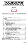
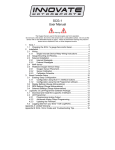
LM-2
Digital Air/Fuel Ratio Meter
User Manual
Note: This manual assumes that firmware version 1.10 is installed on your LM-2
Warning!
The Oxygen Sensor used in this device gets very hot in operation.
Do not touch the hot sensor. Do not let a hot sensor touch a combustible
surface. Do not use the sensor with or near flammable liquids or gases. Failure
to heed these warnings may result in severe burns, explosions or fires.
When installed in the exhaust, the oxygen sensor MUST be connected and
operating with the LM-2 whenever the car is running. An un-powered oxygen
sensor will be quickly damaged when exposed to hot exhaust gases.
TABLE OF CONTENT
1
LM-2 ....................................................................................................................................................... 3
1.1 Main Screen ..................................................................................................................................... 5
1.2 Status Bar ........................................................................................................................................ 5
1.3 Configuration Menu Screen ............................................................................................................. 7
1.4 Recording......................................................................................................................................... 8
1.5 Playback........................................................................................................................................... 8
2 Air/Fuel Ratio Setup............................................................................................................................... 9
2.1 Sensor Calibration............................................................................................................................ 9
2.2 Sensor Placement.......................................................................................................................... 10
2.3 Calibration Schedule ...................................................................................................................... 11
3 Software (LogWorks 3 and LM Programmer) ...................................................................................... 13
3.1 Installing software and Connecting the LM-2 to computer............................................................. 13
3.2 Updating Firmware......................................................................................................................... 14
3.3 Downloading Logs from Memory Card .......................................................................................... 15
4 OBD-II .................................................................................................................................................. 16
4.1 Locate the OBD-II Connector in your vehicle................................................................................. 16
4.2 Selecting Channels on the LM-2.................................................................................................... 17
4.3 Selecting Channels with the LM Programmer software................................................................. 18
4.4 OBD-II Channel Speed .................................................................................................................. 19
4.5 Set the Priority of OBD-II Inputs (Optional).................................................................................... 21
4.6 Check Vehicle Trouble Codes on the LM-2 ................................................................................... 25
4.7 Clear Vehicle Trouble Codes on the LM-2..................................................................................... 25
4.8 Check and Clear Vehicle Trouble Codes with LM Programmer .................................................... 26
4.9 OBD II Basics................................................................................................................................. 27
5 Analog Cable ....................................................................................................................................... 29
5.1 RPM Input ...................................................................................................................................... 29
5.1.1
Enable/Disable RPM .............................................................................................................29
5.1.2
Configure RPM ...................................................................................................................... 29
5.2 Analog Inputs ................................................................................................................................. 31
5.2.1
Enable/Disable Analog Inputs ............................................................................................... 31
5.2.2
Wiring Analog Inputs ............................................................................................................. 31
5.3 Analog Outputs .............................................................................................................................. 32
5.3.1
Programming the analog outputs .......................................................................................... 32
5.3.2
Advanced output programming ............................................................................................. 33
5.3.3
Wiring Analog Outputs .......................................................................................................... 34
6 Tips, Tricks, & Troubleshooting ........................................................................................................... 35
6.1 Air/Fuel and Lambda...................................................................................................................... 35
6.2 General measurement requirements ............................................................................................. 36
6.3 Vehicles with ‘smog-pumps’........................................................................................................... 36
6.4 Single Cylinder Engines ................................................................................................................. 36
6.5 Diesel Engines ............................................................................................................................... 36
6.6 Sensor Timing Errors ..................................................................................................................... 37
6.7 Connecting the LM-2 to simulate a narrow band oxygen sensor .................................................. 37
6.8 Attenuating a Tach Signal .............................................................................................................. 39
6.9 OBD II connection diagnostic trace................................................................................................ 39
Appendix A: Specifications.......................................................................................................................... 40
Appendix B: Limited Warranty .................................................................................................................... 41
Appendix C: Connectors ............................................................................................................................. 42
Appendix D: Supported PIDs ...................................................................................................................... 44
Appendix E: Error Codes and Troubleshooting Tips .................................................................................. 46
7 Revision History ................................................................................................................................... 47
2
Document # 31-0008
LM2_Manual_1.2.doc
1 LM-2
The LM-2 is a single or dual channel wideband controller with a built-in OBD II scan tool,
RPM input, four analog inputs, MTS serial I/O, SD memory card recording and two
analog outputs per wideband channel. The following screens will help you get familiar
with the unit.
Front
LCD Display
Mode Button
Press once to
cycle through
channel display
screens. Press and
hold to enter menu.
Up Arrow
Scroll through available
channels. Move through
menu
Enter
Accept an entry in the menu
screen.
Cancel Button
Press to cancel out
of menu or to stop
recording.
Down Arrow
Scroll through available
channels. Move through
menu
Record
Press once to
record or press again
to stop recording. Press
and hold to force a new log.
Left
Inductive Clamp
3
MTS Serial IN
MTS Serial OUT
Document # 31-0008
LM2_Manual_1.2.doc
Top
SD Memory Card Slot
USB Connector
Bottom
Sensor Input # 2 (Enabled with
the Dual Channel version)
Analog Cable
Sensor Input # 1
Power
OBD-II Connector
4
Document # 31-0008
LM2_Manual_1.2.doc
1.1 Main Screen
There are 5 different screen view options. These can be cycled by pressing the Mode
button.
One Channel
Two Channels
Four Channels
One Channel Line Graph
One Channel Fill Graph
1.2 Status Bar
The bottom edge of the screen is the status bar and will look something like this:
The left most portion is the current time (which can be set via menu and is set
automatically by LM Programmer).
5
Document # 31-0008
LM2_Manual_1.2.doc
During Recording, an upper case ‘R’ and a counter will display on the lower left:
Counting minutes and seconds of recording.
Similarly, during playback a upper case ‘P’ and a counter will display:
Counting elapsed time during playback.
Note: If Recording does not start (see later section), also look here, the word “Card?”
will appear if no SD card is detected when Record is selected. The word “Full!” will
appear if you have either filled the SD card, or exhausted the available log names (see
section on recording).
Moving to the right, the next two indications are O2 sensor status, which can be one of
the following:
HW
Cal
O2
L
Ex
- Heater Warm-up
- Calibrating
- Reading O2 context (lambda over 8.something)
- Reading Lambda (or AFR)
- Error, Check Appendix E for error code meanings and trouble shooting tips
Note: If the LM-2 is a single channel model, the second indication will be blank, not an
error code.
The next indicator, “R”, will appear when a) RPM is selected for logging/use (see
menus) and b) an RPM signal is detected. Note, when RPM is enabled, but no RPM
signal is detected, this symbol will appear in lower case (“r”).
The “A” indicator means that the 4 Analog Inputs are selected for logging/Use (see
menus). It is all or nothing. The display will be blank if disabled.
The “O” indicates that an OBD-II connection is active. This indicator will blink at the
relative ‘sample rate’, which will vary on the number of channels selected and the
vehicle’s protocol. The display will be blank if the unit is not connected to an OBD-II port.
The blinking “M” indicates that MTS serial data is being generated. This will blink at the
relative MTS packet rate (for comparison with the O indicator). If the unit is not the
“head” unit, then this will only blink when packets are being received via the Serial In
6
Document # 31-0008
LM2_Manual_1.2.doc
connector.
Last, “H” indicates that the unit is the MTS head unit. If the unit is not head this indicator
will appear as a “-“
1.3 Configuration Menu Screen
To enter the Configuration Menu Screen press and hold the Mode button.
Navigating the Menu:
“Enter” Accepts
“Cancel” Returns one menu level
“Mode” Returns to Main Screen
Arrows adjust selection or value
“Record” has no effect
When “Mode” is first pressed, the following choices appear:
•
•
•
•
•
•
•
•
Display AFR or Lambda. The factory default setting is AFR.
Calibrate Sensors - Free Air Calibrate ALL O2 sensors connected will be
calibrated
RPM – Enable/Disable RPM and Configure RPM.
Analog Inputs- Enable/Disable Analog Inputs and Configure Inputs.
OBD-II - Configure Number of Channels (0-16), Channel Use, Get/Clear DTC
codes Display in Metric/Imperial Units, and Start Trace File.
Playback Log
Reverse/Normal Display
Set Date/Time - Set the current date/time
Important Note: Entering the Configuration Menus will stop recording and
suspend MTS packet output
7
Document # 31-0008
LM2_Manual_1.2.doc
1.4 Recording
To start a record session press the Record button. The LM-2’s display will then inverse
and the status bar will display an upper case ‘R’ and a counter on the lower left hand
corner of the screen. To stop the record session press the Record button a second time.
Note: Loss of power while the LM-2 is recording will lose all data from the current
session being recorded.
When recording is first activated, a file is created. The naming convention is:
mmddyyXX.d32
These are the month, day, and year that the file is created. The XX is to accommodate
multiple files on the same day (counting begins at “00”).
Once a file exists, sessions are appended to it for each additional recording. The
exceptions to this are:
1. The MTS channel count/type has changed
2. The user requests a new log file by pressing and holding “Record” (or holding the
record button on an external XD-16.)
The first instance will occur if devices are added or removed the MTS serial chain , or if
channels are enabled/disabled on the LM-2.
When a new file is created, it will be given the day’s date and a unique counter:
07010800.d32
07010801.d32
Etc
Note: When the LM-2 is recording the display will inverse. In the status bar, an upper
case ‘R’ and a counter will display on the lower left
1.5 Playback
1. Press and hold the Mode button to go into the Configuration Menu Screen.
2. Select Playback log and press the Enter button.
3. A list of available logs present on the memory card will be displayed. Make your
selection and press the Enter button.
Note: Depending on the size of the log the next screen some time to appear.
4. A list of available sessions will be displayed. Make your selection and press the
Enter button.
5. The selected session will now start playing. The status bar will display an upper
case ‘P’ and a counter on the lower left hand corner of the screen.
8
Document # 31-0008
LM2_Manual_1.2.doc
Note: While the session is being played back you can pres the Menu button to cycle
through the different display screens and you may also press the Arrow buttons to
change the displayed channels.
6. To stop the playback you may press the Cancel button at any time or allow the
playback to run it’s course.
2 Air/Fuel Ratio Setup
Innovate Motorsports’ ‘Direct Digital’ wideband measurement principal allows you to
calibrate the sensor to compensate for sensor wear. This procedure takes no more than
a couple seconds and it will insure the most accurate readings throughout the oxygen
sensor’s life.
2.1 Sensor Calibration
The calibration procedure requires that the oxygen sensor be in free air, not in the
exhaust.
1. Connect the oxygen sensor to the provided sensor cable and then to the
appropriate port on the LM-2. Note: The dual channel LM-2 model allows you to
connect both oxygen sensors to the unit at the same time to do the calibration
simultaneously.
2. Connect the LM-2 to the cigarette power plug with the provided cigarette power
adapter.
3. The sensor(s) will start warming up. The LM-2
will display WXX, where XX is the percentage of
temperature reached. Notice the status bar
displaying a ‘W’.
4. Next is the calibration procedure. Press and hold the Mode button until the
Configuration Menu appears. Select ‘Calibrate Sensors’ and press the Enter
button.
5. The display will momentarily display ‘Cal’ and then it will switch to reading a
percentage of oxygen. If the oxygen content now differs from 20.9% by more
than 0.6%, repeat the calibration.
9
Document # 31-0008
LM2_Manual_1.2.doc
6. The LM-2 is calibrated and ready for use.
The LM-2 must be powered by the cigarette adapter (12 volts) in order to
properly heat the Oxygen sensor and measure Air/Fuel. If the unit is only to be
used connected to the OBDII port it will properly function as a scan tool.
2.2 Sensor Placement
Using a bung is the preferred method for mounting the O2 sensor for both catalytic and
non-catalytic cars.
On CATALYTIC CONVERTER equipped vehicles:
Install the oxygen sensor’s bung upstream from the catalytic converter (a bung and
plug is included in the LM-2 kit). The bung must be installed in the exhaust pipe at
the side or on top, NOT on the bottom of the exhaust pipe. Any decent muffler or
exhaust shop can do this for you. The wide-band oxygen sensor is then installed into
the bung to take a reading. (Insert the plug into the bung when not in use). The ideal
position is between 10:00 and 2:00 position.
On NON-CATALYTIC converter vehicles:
You have the option with non-catalytic cars to also use an exhaust clamp as
described below. Use of a bung is the preferred method for mounting the 02 sensor
for both catalytic and non-catalytic cars.
On TURBO CHARGED vehicles:
Install the bung downstream from the turbo but before the catalytic converter. The
high exhaust pressure before the turbo interferes with the lambda measurement and
the high exhaust temperatures encountered there can damage the sensor.
Alternatively you can also use the optional exhaust clamp (part number 3728) to sample
exhaust gases at the end of the tail pipe.
10
Document # 31-0008
LM2_Manual_1.2.doc
Do NOT install the Bung below the 3 o'clock or 9 o'clock position. Condensation
can form in the exhaust pipe and permanently damage the sensor. 6 o’clock is the
absolute worst position to mount the sensor.
Wide band oxygen sensors, like the one shipped with the LM-2, are designed to
work with unleaded gasoline. Use with leaded gasoline will significantly reduce the
lifespan of the sensor. The reduction is directly proportional to the metal content of the
fuel and the tune of the engine. In most cases, a wide band sensor will provide
accurate measurements somewhere between 50 hours and 500 hours with leaded fuel.
WHEN INSTALLED IN THE EXHAUST, THE OXYGEN SENSOR MUST BE
CONNECTED AND OPERATING WITH THE LM-2 WHENEVER THE CAR IS
RUNNING. AN UN-POWERED OXYGEN SENSOR WILL BE DAMAGED WHEN
EXPOSED TO EXHAUST GAS IF NOT PROPERLY POWERED.
The maximum temperature of the sensor at the bung (the sensor hexagon)
should not exceed 500 oC or 900 oF. If these temperatures are exceeded in your
application you should either install a double length bung (one inch) or the Innovate
Motorsports Heat-Sink Bung extender (HBX-1).
The double length bung is also recommended for situations where airflow is restricted.
It is NOT a good idea to do a sensor warm-up prior to starting the vehicle.
Depending on the climate and the sensor position in the exhaust, condensation can
form in the exhaust pipes. This condensation could then be blown by the exhaust
stream against the hot sensor when the car is started. The resulting heat shock can
permanently damage the sensor.
2.3 Calibration Schedule
Normally aspirated (daily driver)
- Calibrate before installation of new sensor
- Calibrate new sensor again after 3 month of use
- Thereafter calibrate once a year or every 20,000 miles, whichever comes first
11
Document # 31-0008
LM2_Manual_1.2.doc
Turbo Application, daily driver (tuned rich)
- Calibrate before installation of new sensor
- Calibrate new sensor again after 3 month of use
- Thereafter calibrate twice a year or every 10,000 miles, whichever comes first
Race Application
- Calibrate before first installation of new sensor
- Calibrate once per race weekend
- For added sensor life we also recommend our optional double length bung (part
number 3764
Dyno use:
- Calibrate a new sensor
- Calibrate every 2-3 days, depending on usage
12
Document # 31-0008
LM2_Manual_1.2.doc
3 Software (LogWorks 3 and LM Programmer)
It is important to install the provided software to the computer prior to connecting
the LM-2. Failure to do so may lead to connection complications.
3.1 Installing software and Connecting the LM-2 to computer
1. Install the CD that came with your LM-2 in your personal computer.
2. The installer will automatically start, follow the prompts to install the software.
3. Connect one end of the USB cable to the LM-2 and the other end to your computer.
4. Power up the LM-2. Note: The unit is not powered up by the USB connector.
5. Windows will now recognize the device and prompt the “New Hardware Wizard.”
Click Next.
13
Document # 31-0008
LM2_Manual_1.2.doc
6. Select “Install the Device Automatically” and click Next.
7. A progress screen will appear. During this installation process the screen below will
pop up. Click “Continue Anyway.”
8. The last screen will inform you that the unit has been successfully installed. Click
“Finish.” The unit is installed and ready to use.
3.2 Updating Firmware
1. Connect the LM-2 to your computer with the provided USB cable.
2. Power up the LM-2. Note: The unit is not powered up with the USB connector.
3. Launch LM Programmer. The LM Programmer application can be launched from
Start->Programs->LogWorks3->LM Programmer from the Windows task bar.
4. Once connected the LM Programmer will display the current version of the
firmware that is installed in the LM-2. Do not update the firmware if the versions
are the same. A firmware update should only be necessary if there has been a
new release.
5. On the very first tab of LM Programmer you will see a button labeled “Update
Firmware,” click this button.
14
Document # 31-0008
LM2_Manual_1.2.doc
6. Select the firmware file with the dld extension.
7. The software will now prompt you to put the LM-2 in “Boot Mode.” In order to
accomplish this you must power the unit off. Next, while pressing the Mode
button on the LM-2, power the unit back ON. The LM-2’s display will show that it
is now in “Boot Mode.” Press the OK button on the software to start the firmware
reflash.
8. You may disconnect and exit out of the software once the firmware update is
finished.
3.3 Downloading Logs from Memory Card
Note: An SD memory card reader is necessary to retrieve logs from the memory card.
The logs can not be downloaded through the LM-2..
1. Remove the memory card from the LM-2 and insert it in your SD memory card
reader.
2. Launch LogWorks 3. The LogWorks 3 application can be launched from Start>Programs->LogWorks3->LogWorks3 from the Windows task bar.
3. Click on File->Import/Download->Import LM-2 Log.
4. A window will pop up which will allow you to select the desired log from the
memory card. Click Open.
15
Document # 31-0008
LM2_Manual_1.2.doc
4 OBD-II
The LM-2 allows you to read up to 16 channels of “OBD-II” (“On Board Diagnostic)
information directly from your vehicle’s engine control unit (ECU). A log file can be
recorded on the included SD card, and played back on a personal computer using
Innovate’s LogWorks software (included with the LM-2) or other 3rd party MTScompatible applications.
4.1 Locate the OBD-II Connector in your vehicle
This is typically the most dangerous aspect of LM-2 installation. A safety helmet is
wholly optional, but a flashlight can be extremely helpful. The connector is required to
be within 3’ of the driver’s seat in the vehicle and accessible without tools. Generally it
is somewhere just behind the bottom edge of the dashboard, immediately in front of the
driver, but it may be in a relatively obscure place, like hidden behind an ashtray.
If you are unable to locate the connector by inspection your best bet would be to either
ask a mechanic familiar with the make and model vehicle or locate an online
hobbyist/enthusiast group devoted to your vehicle.
Here is a sample OBD-II connector. Please
note that the orientation of the connector varies
from vehicle to vehicle.
For example, in this example, the wide part of
the connector is ‘down’. In other installations
this wide part of the connector will be up. In still
other installations the entire connector may be
‘facing’ the floorboard.
On many newer vehicles the connector is
concealed behind a small door or removable
plastic cover plate.
Also, the connector itself may be covered with a
small, removable, rubber cap.
16
Document # 31-0008
LM2_Manual_1.2.doc
4.2 Selecting Channels on the LM-2
1. Press and hold the Mode button to go into the Configuration Menu Screen.
Select OBD-II and press the Enter button.
2. Select Configure OBD-II.
3. You will now be given the option to select a particular
OBD II protocol or you can leave it on ‘Automatic’ which
will scan all available protocol until it connects. Press
Enter.
4. Select the number of OBD II channels to read (A maximum of 16 channels can
be selected). It is recommended to start off with 2 to 3 channels to evaluate the
speed at which the ECU delivers data. Press Enter.
5. You will now be able to scroll through all available
channels and make your selection. Note: If you are
connected the unit will filter and only display the available
channels available by the ECU. Press Enter.
6. Chose if the channel is Low or High Priority. Please see
section 3.5 of the manual. Press Enter to move to the next channel.
7. After all channels have been selected the unit will return to the main screen.
If a PID (channel) is not available for the particular vehicle, the data will read 0)
17
Document # 31-0008
LM2_Manual_1.2.doc
4.3 Selecting Channels with the LM Programmer software
1. Connect the LM-2 to your computer with the provided USB cable.
2. Power up the LM-2. Note: The unit is not powered up with the USB connector.
3. The LM Programmer application can be launched from Start->Programs>LogWorks3->LM Programmer from the Windows task bar. A small dialog box
will appear indicating that the program is looking for connected Innovate Devices,
then the main dialog should appear.
4. The Inputs tab allows you to set the number of MTS channels to generate.
5. Click the Inputs tab. Only the number of channels selected on the
Protocol/Channels page can be edited. The available values for logging on the
connected ECU are listed in the drop list for each Input. Some vehicles will
support larger lists than others.
6. Hit the ‘Program’ button to send the configuration.
Also, it cannot be stressed enough that different ECUs will have dramatically
different response speeds. Below are two extreme examples.
18
Document # 31-0008
LM2_Manual_1.2.doc
4.4 OBD-II Channel Speed
The first is a log trace of one channel (RPM) from a 2001 Lexus:
Notice that the data appears ‘steppy’ and, based on the timeline, appears to be
updating about 6 times per second.
Next we have a log trace of 16 channels (RPM, MAF, MAP, TP, you name it) from a
2006 Saturn:
19
Document # 31-0008
LM2_Manual_1.2.doc
Even if we zoom in to a closer time scale, the data is quite smooth. Performance is
controlled by two things:
•
•
The Connection Speed
ECU Responsiveness
The Lexus in the first example is using ISO 9141 and 10.4K bits per second. The
Saturn is using ISO 15765 (CAN) at 500K bits per second. So it is easy to understand
the difference in performance.
However, the responsiveness of the ECU also can be a significant factor. Consider this
log from a 2006 Pontiac GTO:
20
Document # 31-0008
LM2_Manual_1.2.doc
Like the Saturn, it is connected using 500K bit CAN, but we can begin to see some
‘steppiness’ in the RPM channel with only 8 channels being collected. In addition, some
values, like the Calculated Load are courser still. Presumably because the ECU itself is
only calculating them a few times per second.
With this in mind, it is probably best to assign channels only a few at a time and then
select “Program”. The ECU will disconnect, reconnect with the new choices, and then
the overall sample rate of the current settings can be observed using the blinking
vehicle light on the LM-2.
It is then up to you, the user, to decide what is an acceptable balance.
4.5 Set the Priority of OBD-II Inputs (Optional)
Next to each Input Selection on the Inputs page In LM Programmer there is a small
checkbox labeled “Low Priority.” This option is also available when selecting channels
through the LM-2’s display:
21
Document # 31-0008
LM2_Manual_1.2.doc
Since it is often a battle getting an ECU to deliver data fast enough, it is reasonable to
ask why one would lower the priority of a channel? The simple answer is, some ECU
values just do not change very fast. So, reading those values less often means that
values that do change quickly can be read more often. To understand how this works
let’s take a look at how the LM-2 normally reads values:
As we can see from the diagram on the right, values are
read from the ECU one after another, in a loop. Since takes
ECU has certain amount of time to respond to each query,
longer the list of channels, the longer it takes to complete
the loop. Obviously, the longer to takes to complete the
loop, the larger the time gap between each read of
Repeat
individual value.
Read 1st
Value
the
the
Read 2nd
Value
an
Read 3rd
Value
Read last
Value
Read 1st
Value
Read 2nd
Value
Repeat
Now let’s look at how Low Priority Values fit into this.
Instead of being read once each time through the loop, only one
Low Priority value is read each time through the loop. So, if you
have three low priority values, it will take three passes of the
loop to read them all once.
Read last
Value
22
Read one Low
Priority Value
Low Priority
Value List
Document # 31-0008
LM2_Manual_1.2.doc
With our racetrack shaped diagram fresh in mind, let’s look at Low Priority inputs in
practice. In this example the vehicle can provide four LM-2 channels that update at full
MTS rates. Even four channels are still very usable. For example, here is RPM,
SPARKADV (ignition timing), FUEL1_OL (Open Loop Status) and VSS (Vehicle Speed
Sensor):
But what would happen if we also added ECT, IAT, MAF, and MAP? If we left all our
channels at normal priority, some critical channels may not be fast enough for our
purposes:
23
Document # 31-0008
LM2_Manual_1.2.doc
But not all channels change quickly and we are more concerned with some channels
than others. For example, let’s say we are primarily concerned with RPM, SPARKADV,
and FUEL1_OL. We’d like VSS, IAT, ECT, MAF, and MAP but we do not care if they
update slowly. So, we can mark those channels as low priority:
24
Document # 31-0008
LM2_Manual_1.2.doc
Now, when we log the data, RPM, SPARKADV, and FUEL1_OL, look like our original
four channel log:
This extra resolution comes at the expense of our Low Priority inputs. These channels
all share the ECU ‘bandwidth’ once used by VSS alone. But, this lets us have high
resolution critical data combined with lower priority, lower resolution data in the same
log.
4.6 Check Vehicle Trouble Codes on the LM-2
1. To view your vehicle trouble codes press and hold the Mode button to go into the
Configuration Menu Screen.
2. Select OBD-II and press the Enter button.
3. Select “Get DTC’s”. A list (if any) of error codes will be displayed on the screen. To
see the specific meaning of the error code, select it and click Enter. Click Enter
again to return to the list.
4. Press Mode or Cancel to exit.
4.7 Clear Vehicle Trouble Codes on the LM-2
1. To clear your vehicle trouble codes press and hold the Mode button to go into the
Configuration Menu Screen.
25
Document # 31-0008
LM2_Manual_1.2.doc
2. Select OBD-II and press the Enter button.
3. Select Clear DTC Codes and press the Enter button.
4.8 Check and Clear Vehicle Trouble Codes with LM Programmer
1. Connect the LM-2 to the vehicle via the OBD II connector.
2. Power up the LM-2. Note: The unit is not powered up with the USB connector.
3. The LM Programmer application can be launched from Start->Programs>LogWorks3->LM Programmer from the Windows task bar. A small dialog box
will appear indicating that the program is looking for connected Innovate Devices,
then the main dialog should appear.
4. Click the tab labeled “Trouble Codes.”
Standard Trouble Codes are listed both with a number and a description. Manufacturer
specific codes will generally just appear as a number, though sometimes, the general
category can be identified.
You can request that the ECU clear the pending codes using the Clear and Refresh
button at the bottom right corner of the page.
Note: On some vehicles, the ignition must be on, but the vehicle not started, for the
Clear DTC request to be accepted.
26
Document # 31-0008
LM2_Manual_1.2.doc
4.9 OBD II Basics
OBD stands for “On Board Diagnostics”. It represents a collection of industry and
legislative standards for getting basic diagnostic information from passenger vehicles
sold in the US since Model Year 1996. The “II” means that this is the second attempt at
standardizing across all makes and models.
OBD-II standardized what type of information ECU’s must provide, but did not set a
single standard on how the information should be communicated (typically called a
‘Communication Protocol’ or just ‘Protocol’) or even the electrical characteristics of the
communication link itself (usually referred to as the ‘Physical Communication Link’).
Instead, the various car manufacturers were each allowed to keep using their own
existing protocols and physical links. We can see this compromise on the OBD-II
connector itself:
Pin Assignments:
1. 2. J1850+
3. 4. Chassis Ground
5. Signal Ground
6. CAN (J2284) High
7. ISO 9141 K line
8. -
9. 10. J185011. 12. 13. 14. CAN (J2284) Low
15. ISO 9141 L line
16. Battery Power
Note: Pins marked with ‘-‘ are sometimes used for make/model specific purposes.
Looking closely we can see that there are really three different electrical ‘pairs’, each
representing a different type of physical communication link. J1850 (pins 2&10), CAN
(pins 6&14), and ISO (pins 7&15). On top of these three physical communication links
are six different communication protocols:
•
•
•
The J1850 pair uses either J1850pwm (Ford) or J1850vpw (GM)
The CAN pair uses either ‘standard’ ISO 15765 or ‘extended’ ISO 15765
The ISO pair use either ISO 9141 or ISO 14230 (sometimes referred to as
KWP2000)
So, in order to get OBD-II information from any OBD-II compatible vehicle an interface
needs to ‘speak’ six different languages over three different types of electrical links.
Starting in MY2008, this will drop to one electrical link (CAN) and two protocol variations
27
Document # 31-0008
LM2_Manual_1.2.doc
(ISO 15765 standard or extended) but that still leaves about 12 years of ‘compromise’
vehicles. Fortunately the LM-2 can take care of most of this complexity automatically.
So, from a user’s point of view OBD-II can primarily be considered on the basis of what
is consistent and standard, namely:
•
•
The Connector
The Information Provided
OBD-II information comes in two basic flavors, “PIDs” and “DTCs”. PIDs, or
“Parameter IDs”, represent real time measurements about the state of the power plant;
information such as RPM and ignition timing. The definitive reference on these
standard PIDs is the J1979 Standard (last revised 4/2002), published by the SAE
International (www.sae.org). Not all ECUs support all PIDs, but the LM-2 understands
and converts over 100 of the most common ones (see Appendix B for a complete list).
DTCs, or “Diagnostic Trouble Codes” are, as the name implies, problems reported by
the ECU. Codes can be “Standard” or “Manufacturer Controlled”. An example of a
standard code would be P0051. This code means”HO2S Heater Control Circuit Low,
Bank 2, Sensor 1” for all OBD-II vehicles. But P1336 is in the non-standard code range.
The exact meaning is up to the vehicle maker. Without information from the car maker
all we know from the code itself is that the beginning, P13xx, suggests that it is in the
general category of “Ignition System or Misfire.”
The definitive listing of standard DTCs is J2012 (last revised 4/2002), also published by
SAE International. All these standard DTCs are reported as both a number and in plain
English by the LM-2. Manufacturer Controlled DTCs are reported solely by number.
28
Document # 31-0008
LM2_Manual_1.2.doc
5 Analog Cable
The provided analog cable has 14 stripped ends. The wire assignments are as follows:
Analog Out 1 + (Lime Green)
Analog Out 2 + (Brown/White)
Analog Out 1 – (Yellow)
Analog Out 2 – (Dark green)
Analog In 1 + (Purple)
Analog In 1 – (Black)
Analog In 2 + (Grey)
Analog In 2 – (Brown)
Analog In 3 + (White)
Analog In 3 – (Red)
Analog In 4 + (Peach)
Analog In 4 – (Orange)
RPM + (Black/White)
RPM – (Blue)
5.1 RPM Input
The LM-2 has a direct tach signal input signal. This input can be used to feed a signal
from the negative lead of a coil, ECU, negative lead of an injector, or ignition box (i.e.
MSD 6AL). This tach signal can be feed to the RPM + (Black/White) wire. The negative
wire (Blue) can be connected to ground if a tach signal is not being registered.
5.1.1 Enable/Disable RPM
Enabling the RPM channel will allow you to display the channel on the
LM-2 and log it on the SD memory card. Disabling the channel will do the exact
opposite.
1. Press and hold the Mode button to go into the Configuration Menu Screen.
2. Select RPM and press the Enter button.
3. You will not have the option to Enable/Disable RPM.
5.1.2
1.
2.
3.
4.
Configure RPM
Press and hold the Mode button to go into the Configuration Menu Screen
Select RPM and press the Enter button.
Select Configure RPM and press the Enter button.
You will now have the option of selecting the Tach input source, use the arrows
to change the selection. 0 is the input from the Analog Cable, 1 is the input from
the Inductive Clamp. Press Enter.
5. You will not have the option to select the ‘Polarity.’ Rising Edge is the most
common way to measure a tach signal. If you find that your readings are very
erratic you should change this setting to Falling Edge. Press Enter.
6. Select the RPM range. Options are 10230 RPM or 20460 RPM. Press Enter..
7. Select Pulses per Rotation. Below are two tables to aid in your selection:
29
Document # 31-0008
LM2_Manual_1.2.doc
Cylinder number and RPM calibrate number 4 Cyl engine
Number
4-Stroke
Calibrate
Comment
of
pulses/CrankNumber
Cylinders Rotation
1
1/2
1
Use also when using inductive
clamp on spark wire or power
wire of COP system of 1 cylinder
only for all cylinder numbers
2
1
2
Use also when using inductive
clamp on spark wire or power
wire of Waste spark coil of 1
cylinder only.
Waste spark system:
1 coil for every 2 cylinders.
3
1-1/2
3
4
2
4
5
2-1/2
5
6
3
6
8
4
7
10
10
8
12
12
9
Cylinder number and RPM calibrate number 2 Cycle and Rotary Engine
Number
2-Stroke
Calibrate
Comment
of
pulses/CrankNumber
Cylinders Rotation
1
1
2
Use also when using inductive
clamp on spark wire or power
wire of COP system of 1 cylinder
only for all cylinder numbers
Also use for rotary engine.
2
2
4
Use also when using inductive
clamp on spark wire or power
wire of Waste spark coil of 1
cylinder only.
Waste spark system:
1 coil for every 2 cylinders.
3
3
6
4
4
8
5
5
8
6
6
9
Once the selection is made press Enter. You will be brought back to the main
screen.
30
Document # 31-0008
LM2_Manual_1.2.doc
5.2 Analog Inputs
The LM-2 has 4 analog inputs for external 0-5V sensors. Each input has a
corresponding positive lead (+) for the signal and a negative lead (–) for the ground
signal source. It is important to wire both of these leads to get accurate measurements.
5.2.1 Enable/Disable Analog Inputs
1. Press and hold the Mode button to go into the Configuration Menu Screen.
2. Select Analog Inputs and press the Enter button.
3. You will not have the option to Enable/Disable the Analog Inputs.
5.2.2 Wiring Analog Inputs
The LM-2’s inputs are differential. A differential input does not measure a signal relative
to electrical ground. Instead it measures the relative voltage between two signals. That
is, it does not measure the '+' signal in relationship to ground, but in relationship to the '-'
signal. It measures the 'difference' between them (hence the name differential input!)
Below you will find diagrams that should better illustrate the correct way to wire in
external sensors. Please note that the + lead is signal positive, NOT power.
31
Document # 31-0008
LM2_Manual_1.2.doc
5.3 Analog Outputs
5.3.1 Programming the analog outputs
1. Connect the LM-2 to your computer with the provided USB cable.
2. Power up the LM-2. Note: The unit is not powered up with the USB connector.
3. Launch LM Programmer. The LM Programmer application can be launched from
Start->Programs->LogWorks3->LM Programmer from the Windows task bar.
4. Select one of the Analog output tabs. The Analog output page looks like this:
This shows the analog output voltages versus Lambda for one of the two analog outputs.
The graph display is automatically scaled to the selected voltages. For each output you
can specify a minimum and maximum lambda value and the associated voltages. Below
the minimum and above the maximum lambda values the output voltages stay constant
at the associated programmed voltage.
By selecting the ‘use Air-Fuel-Ratio’ button you can program the curve by AFR instead
of Lambda. This does not change the programming, only the representation of the data.
When programming by AFR the LM Programmer converts the number to Lambda
before programming the LM-2.
Click the ‘Program’ button to download the new data into the LM-2. Once the unit is
programmed the ‘Program’ button will grey out.
32
Document # 31-0008
LM2_Manual_1.2.doc
Note for Dual A/F channel units: You can program each analog output to represent the
data from sensor 1 or 2 by selecting the appropriate radio box.
Factory Programmed Defaults:
Single Channel A/F units: Analog Output 1 is programmed to output between 0 V for an
AFR of 7.35 (gasoline) and 5.0V for an AFR of 22.39. Analog Output 2 simulates a
typical narrow band oxygen sensor. The configuration is 1.1 V for an AFR of 14 and .1 V
for an AFR of 15.
Dual Channel A/F units: Analog Output 1 and Analog Output 2 are programmed to
output between 0 V for an AFR of 7.35 and 5.0V for an AFR of 22.39. They represent
sensor 1 and sensor 2, respectively.
Other curves, of course, are easily programmable.
5.3.2 Advanced output programming
The ‘Advanced’ button allows programming to set the analog out update speed and the
voltage output during sensor Warm-up and Error Condition. The factory defaults of the
analog outputs is to update the outputs 1/12 of a second. The factory default voltage
output is set for 0 volts for both the Warm-up and Error Condition.
When setting the LM-2 to the slower response speed settings the measured mixture
data will be averaged over the response time setting before being output.
33
Document # 31-0008
LM2_Manual_1.2.doc
5.3.3 Wiring Analog Outputs
The analog outputs on the LM-2 are differential. As with the analog inputs, the negative
lead (-) must be connected to ground for the readings to be accurate. Below are the
three different ways the analog outputs of the LM-2 can be wired. If you are unsure
whether your analog input is differential or not you may wire the analog output as shown
in diagram 1.
34
Document # 31-0008
LM2_Manual_1.2.doc
6 Tips, Tricks, & Troubleshooting
6.1 Air/Fuel and Lambda
The Stoichiometric AFR value is the AFR multiplier. So for (standard, unblended)
gasoline its 14.7. If you set it to 14.7 the LM-2 display will show 14.7 AFR for Lambda
1.0. If you set it to 6.4 (methanol) the LM-2 will show 6.4 AFR for Lambda 1.0.
You can look at Lambda as the percent of richness. If running Lambda 0.85 (12.5 AFR
for gasoline) you are running 15% rich. For methanol 15% rich means 5.44 AFR. That's
where the value of Lambda comes in. If you run blended fuels where you don't know the
stoich value, you look at Lambda and adjust to 10-20% rich, depending where your max
power is. The % value of richness required by an engine (for max power) does change
relatively little (fairly independent of fuel). But if for example you adjust an engine
running methanol to 12.5 AFR, you would be running so lean that it would probably not
even run.
The LM-2 can be used to read Air/Fuel Ratio (AFR) or Lambda for an engine. For
gasoline-driven engines, the theoretically optimal air fuel ratio for efficiency is 14.7
pounds of air for every pound of fuel. At this ratio, theoretically, all available oxygen in
the air combines with all available fuel. This ratio is called the stoichiometric ratio.
Stoichiometric for different fuels are as follows:
Gasoline
LPG (Propane)
Methanol
Ethanol
CNG
Diesel
14.7
15.5
6.4
9.0
17.2
14.6
The measurement Lambda is the actual air fuel ratio over the stoichiometric ratio. A
Lambda measurement of “1” equates to the air fuel ratio of 14.7 (for gasoline engines).
When Lambda is less than 1 the engine runs “rich”, i.e., unburned fuel exists in the
exhaust stream. If lambda is greater than 1 the engine runs lean, i.e., free oxygen (02) is
present in the exhaust. Depending on the engine, maximum power is typically delivered
when the engine runs slightly rich (for example at lambda values of 0.8 to 0.9 for most
engines). This instrument provides a means to measure the actual air fuel ratio or
lambda in the engine in operation directly from the exhaust. For this a special wide-band
oxygen sensor is used to measure the lambda value derived from the oxygen content
(or lack thereof) of the exhaust gases.
35
Document # 31-0008
LM2_Manual_1.2.doc
6.2 General measurement requirements
The LM-2 measures the air-fuel-ratio by measuring the amount of oxygen in the exhaust
(for lean conditions) or the amount of unburned or partially burned fuel (for rich
conditions). You should correct for the following in order to get optimum results from the
LM-2
1) An exhaust leak will allow oxygen to enter the exhaust stream and therefore
will measure leaner than the engine is actually running. For correct
measurement, air-leaks in the exhaust MUST be prevented under all
circumstances.
2) Missing ignitions (where the air-fuel mixture does not ignite) also pump
unburned oxygen into the exhaust and cause the LM-2 to measure lean.
3) The only circumstance where the LM-2 will measure richer than the engine is
running is if the pressure in the exhaust tract is excessive (and the engine is
running on the rich side to begin with).
6.3 Vehicles with ‘smog-pumps’
Older fuel injected vehicles with a ‘smog-pump’ actually inject air into the exhaust
stream to aid their catalytic converter in the burn-up of unburned or partially burned
fuels. This additional air will make the exhaust look leaner than the engine is running.
For an accurate measure, install the LM-2 sensor up-stream of the outputs of the smogpump. If this is not possible, temporarily disable the smog-pump by removing its drive
belt.
6.4 Single Cylinder Engines
These kinds of engines are difficult to measure at the tail-pipe using an Exhaust Clamp.
The oscillations of the exhaust gas are so large that a lot of outside air enters the
exhaust and prevents correct measurement. Sometimes it helps to temporarily wrap a
piece of heat resistant cloth around the exhaust clamp to prevent outside air from
entering the exhaust.
6.5 Diesel Engines
Diesel Engines and gas turbines run at wide open throttle at all times. They do not have
a throttle but regulate power by the amount of injected fuel. The LM-2 can still be used,
but measurements at idle will read as lean.
36
Document # 31-0008
LM2_Manual_1.2.doc
6.6 Sensor Timing Errors
These errors are typically encountered when the sensor does not have outside air
available as reference gas. If you encounter this error, restart the LM-2 and operate the
sensor in free air (remove from exhaust.) If you still encounter this error, the sensor may
be bad and needs to be replaced.
Replacement sensors are available from your nearest VW dealer under the VW partnumber 021-906-262-B or direct from Innovate Motorsports (part number 3737.)
Sensor timing errors are also common when the sensor overheats. Relocate the sensor
further downstream in the exhaust and/or install a Heat-Sink Bung extender (HBX-1).
This problem is easier to diagnose as you will only see the error code come up at wide
open throttle.
Sometimes it’s possible to encounter Error 08 when the exhaust gas suddenly gets too
rich.
6.7 Connecting the LM-2 to simulate a narrow band oxygen sensor
It is possible to install the wide-band sensor in place of the OEM oxygen sensor. In this
case the meter's analog output signal will replace the OEM oxygen sensor's signal to
the fuel injection computer. Note: Please review your analog output settings, the
configuration for a narrowband is 1.1 V for an AFR of 14 and .1 V for an AFR of 15.
EFI equipped cars typically incorporate a narrow band oxygen sensor. These sensors
are typically 1, 2, 3 or 4 wire sensors. Some vehicles are equipped with oxygen sensors
that do not produce an output voltage but change their resistance depending on exhaust
gas content. These sensors cannot be simulated. They are used in less than 1% of all
vehicles. Refer to your vehicles specifications if you think that your vehicle may be in
this category. The same is true for vehicles already factory equipped with a wide-band
oxygen sensor. These cannot be simulated either.
Some EFI-computers will create a fault when the heater power wires of the oxygen
sensor are disconnected. In this case mount the old oxygen sensor in a safe place (but
not necessarily in the exhaust) and connect the heater wires to it to keep the EFIcomputer happy.
Be careful where you mount the stock sensor, as heated sensors will get hot.
37
Document # 31-0008
LM2_Manual_1.2.doc
To connect the LM-2 to the EFI-computer, first determine what kind of narrow band
sensor is used, then follow the instructions below (you will need a digital multimeter to
determine correct OEM sensor wires):
a. Vehicle has a 1-wire sensor:
Wire analog output 1 directly to the wire.
b. Vehicle has a 2-wire sensor:
While the engine is off determine which of the 2 wires has a low resistance between the
wire and the sensor body. This is the heater power for the sensor. Wire analog output 1
directly to the other wire. Leave the heater power wire unconnected but make sure it
cannot ground itself.
c. Vehicle has a 3-wire sensor:
Typically the 3 wires are: heater power, Ground, and sensor element connection.
Generally they have 1 black wire and 2 white wires. Connect the black wire from the EFI
computer to analog output 1 of the meter. Leave the other wires unconnected but make
sure they cannot contact any metal parts or see above. If the wiring colors are different,
then heater power can simply be determined by measuring the voltage on the wires
when the engine is running. The wire showing 12V or more is the heater power. The
sensor element connection voltage fluctuates around 0.45V when the car is warmed up.
Wire analog output 1 directly to this wire. The Ground connection has low resistance to
chassis ground (less than 1 Ohm). Measure while the engine is off.
d. Vehicle has a 4-wire sensor
Typically the 4 wires are: heater power, heater ground, sensor ground, and sensor
element connection. Proceed as for the 3-wire sensor.
38
Document # 31-0008
LM2_Manual_1.2.doc
6.8 Attenuating a Tach Signal
The problem of an erratic tach signal happens if there is a lot of ringing at high voltages.
To counteract this, it is sometimes necessary to attenuate the tach signal by about 30dB
or so. This is accomplished with a 20k or 50k variable potentiometer which can be
purchased at Radio Shack or any electronics store.
Wiring
1. Connect the tach signal to terminal A.
2. Connect the terminal B to Ground. (Do not connect this to the Blue tach signal
ground on the LM-2’s analog cable.)
3. Connect terminal C to the tach signal input of the LM-2’s analog cable which is
the Black wire with a White stripe.
Tuning RPM
1. Turn the pot all the way to the right (until no RPM is registered).
2. Start turning the pot to the left and stop when you start registering a tach signal
and the LM-2 displays an 'R' on the status bar.
6.9 OBD II connection diagnostic trace
In the rare situation where the LM-2 is not able to connect to the vehicle’s OBD-II
protocol creating a trace file will greatly aid in diagnosing the problem.
1. Press and hold the Mode button to go into the Configuration Menu Screen.
2. Select OBD-II and press the Enter button.
3. Use the Arrow buttons to scroll down to Start Trace File and press the Enter
button. A 't' will alternate (or stay steady) in the "O" spot on the status bar.
4. Connect the LM-2 to the vehicle’s OBD-II port. Wait one minute.
5. Wait one minute, then either press Record to stop, or select "Stop Trace File"
from OBD-II menu.
6. A file named OBDIIxx.TXT will be saved on the SD card (xx counts up to 99).
7. E-mail this file along with the year, make, and model of the vehicle to the support
staff at Innovate Motorsports.
39
Document # 31-0008
LM2_Manual_1.2.doc
Appendix A: Specifications
Power
Power requirements
Single Channel 8-14 Volt / 2 A (max, 1 A nominal)
Dual Channel 8-14 Volt / 4 A (max, 2 A nominal)
Serial Communication
Serial Port Speed
Packet/Logging Speed
Sample Resolution
19.2 kbit/sec
81.92 msec/sample packet
10 bits (0..5V at 0.1% resolution)
Software
Supported OSs
Windows 98, ME, 2000, XP, and Vista
OBD-II Specifications
Number of Channels
Supported protocols
USB Specifications
Protocol Version
Supported OSs
Temperature
Max Operating
Temperature
40
16 (max)
ISO 157650 (CAN), J1850PWM, J1850VPW, ISO 9141,
ISO 14230 (KWP2000)
2.0
Windows 98, ME, 2000, XP, and Vista
-20 to +80 deg Celsius
Document # 31-0008
LM2_Manual_1.2.doc
Appendix B: Limited Warranty
LIMITED WARRANTY
Innovate stands behind the quality of its products. Innovate makes the following warranty to purchasers of
its products: All new Innovate products carry a six-month warranty from the date of purchase. If proof of
purchase cannot be provided, warranty will be determined by date of manufacture.
When Warranty Void
This warranty shall terminate and Innovate shall have no obligation pursuant to it if (i) your Innovate
product has been modified or repaired in a manner not previously authorized by Innovate in writing, (ii)
the identification markings on your Innovate product have been removed, defaced, or altered; (iii) your
Innovate product was subjected to accident, abuse, shipping damage, or improper use; (iv) your Innovate
product was not used or configured as specified in the product manual; or (v) your Innovate product was
subjected to operating conditions more severe than those specified in the product manual.
Exclusions From This Warranty
Oxygen Sensors are excluded from this warranty.
Repairs Under This Warranty
In the unlikely event that your Innovate hardware product should prove defective during the warranty
period, contact Innovate Customer Support for a return material authorization (RMA) at 949-502-8400.
Products returned for service must be securely packed to prevent damage and shipped charges pre paid,
along with proof of purchase and the return material authorization number, to the Innovate repair location
as instructed by Customer Service. Innovate within a reasonable amount of time from its receipt of your
product so shipped, will ship to you, at its option, the repaired product or a new or reconditioned product
of comparable or greater specified functionality. All repaired or replacement products shall be warranted
for the remainder of the original product warranty.
Disclaimer
INNOVATE MAKES NO OTHER EXPRESS OR IMPLIED WARRANTY WITH RESPECT TO YOUR
INNOVATE PRODUCT OTHER THAN THE LIMITED WARRANTY SET FORTH ABOVE. No Innovate
dealer, agent, or employee is authorized to make any modification, extension, or addition to this warranty,
unless enforceable or unlawful under applicable law, INNOVATE DISCLAIMS ALL IMPLIED
WARRANTIES, INCLUDING THE IMPLIED WARRANTIES OF MERCHANTABILITY,
NONINFRINGEMENT, AND FITNESS FOR A PARTICULAR PURPOSE, AND THE LIABILITY OF
INNOVATE, IF ANY, FOR DAMAGES RELATING TO ANY ALLEGEDLY DEFECTIVE PRODUCT SHALL
UNDER ANY TORT, CONTRACT, OR OTHER LEGAL THEORY BE LIMITED TO THE ACTUAL PRICE
PAID FOR SUCH PRODUCT AND SHALL IN NO EVENT INCLUDE INCIDENTAL, CONSEQUENTIAL,
SPECIAL, OR INDIRECT DAMAGES OF ANY KIND EVEN IF INNOVATE IS AWARE OF THE
POSSIBILITY OF SUCH DAMAGES. Some states do not allow limitations on how long an implied
warranty lasts or the exclusion or limitation of incidental or consequential damages, so the above
limitations or exclusions may not apply to you.
41
Document # 31-0008
LM2_Manual_1.2.doc
Appendix C: Connectors
1. Sensor 1 (2 optional)
Pin
1
2
3
4
5
6
7
8
Use
IPUMP+
SENSE/PUMPSHTR
VBAT
SENSE+
SHIELD GND
SHTR
VBAT
Tip: Sensor 1 is near the back of the unit and marked with a circled “1”
2. OBD-II
Pin
1
2
3
4
5
6
7
8
9
10
Use
GND
VBAT
J1850+
J1850ISO K
ISO L
CAN-H
CAN-L
Alt-CAN-H
Alt-CAN-L
Notes: The “Alt CAN” Buss is for instrument monitoring and is not connected to the
J1962 connector in the standard Innovate Cable. Also, the unit can be powered via this
connector for basic operation. However, the O2 sensor circuits are not powered when
OBD-II is used as the power source. The O2 sensor(s) require the normal power
connection.
3. Analog
Looking at the connector with the clip up, pin 1 is the lower left.
PIN
USE
COLOR
1
Analog In 1 Black
2
Analog In 2 Brown
3
Analog In 3 Red
4
Analog In 4 Orange
5
Analog Out 1 Yellow
6
Analog Out 2 Dark Green
7
RPM Blue
8
Analog In 1 +
Purple
9
Analog In 2 +
Grey
10
Analog In 3 +
White
42
Document # 31-0008
LM2_Manual_1.2.doc
11
12
13
14
Analog In 4 +
Analog Out 1 +
Analog Out 2 +
RPM +
Peach
Lime Green
Brown/White
Black/White
Note: All these inputs and outputs are “differential”. That is, the negative inputs must
be connected to ground.
4. Serial Out
Pin
1
2
3
4
Use
RX
TX
GND
GND
5. Serial In
Pin
1
2
3
4
Use
TX
RX
GND
*MTS Sense
6. Inductive Clamp
Pin
1
2
Use
Coil +
Coil –
7. USB
Pin
1
2
3
4
5
Use
NC
DD+
NC
GND
The unit CANNOT be powered from USB. It must be powered via OBD-II or the main
power connector for use.
8. Power
Pin
1,3
2,4
43
Use
GND
VBAT
Document # 31-0008
LM2_Manual_1.2.doc
Appendix D: Supported PIDs
44
Name – Description
Units
Min.
Max
"RPM - Engine RPM",
"TP - Throttle Position(abs)", "%",
"LOAD_PCT - Engine Load(calc)",
"SPARKADV - Timing Advance(cyl1)",
"MAF - Mass Air Flow",
"MAP - Manifold Abs. Presure",
"VSS - Vehicle Speed Sensor",
"ECT - Engine Coolant Temp",
"IAT - Intake Air Temp",
"PTO_STAT - PTO Status",
"FUEL1_OL - Fuel Sys1 Open Loop",
"FUEL2_OL - Fuel Sys2 Open Loop",
"SHRTFT1 - Short Term Fuel Trim 1",
"LONGFT1 - Long Term Fuel Trim 1",
"SHRTFT2 - Short Term Fuel Trim 2",
"LONGFT2 - Long Term Fuel Trim 2",
"SHRTFT3 - Short Term Fuel Trim 3",
"LONGFT3 - Long Term Fuel Trim 3",
"SHRTFT4 - Short Term Fuel Trim 4",
"LONGFT4 - Long Term Fuel Trim 4",
"FRP - Fuel Rail Pressure",
"FRP_MED - Fuel Rail Pressure",
"FRP_HIGH - Fuel Rail Pressure",
"EQ_RAT - Commanded Equiv. Ratio",
"LOAD_ABS - Absolute Load Value",
"EGR_PCT - Commanded EGR",
"EGR_ERR - EGR Error",
"TP_R - Throttle Position(rel)", "%",
"TP_B - Throttle Position B(abs)",
"TP_C - Throttle Position C(abs)",
"APP_D - Acc. Pedal Position D",
"APP_E - Acc. Pedal Position D",
"APP_F - Acc. Pedal Position D",
"TAC_PCT - Commanded Throttle",
"EVAP_PCT - Commanded Evap. Purge",
"EVAP_VP - Evap. Vapor Pressure",
"AIR_UPS - Secondary Air DNS",
"AIR_DNS - Secondary Air DNS",
"AIR_OFF - Secondary Air DNS",
"FLI - Fuel Level Indicator",
"BARO - Barometric Pressure",
"AAT - Ambient Air Temp",
"VPWR - Control Module Voltage",
"MIL - Malfunction Indicator Lamp",
"DTC_CNT - DTC Count",
"MIL_DIST - Distance MIL active",
"MIL_TIME - Hours MIL active",
"CLR_DIST - Distance MIL clear",
"WARM_UPS - Warm Ups MIL clear",
"RUNTM - Run Time",
"O2S11 - O2 Sensor(NB) 1-1",
"SHRTFT11 - O2 Fuel Trim 1-1",
"O2S12 - O2 Sensor(NB) 1-2",
"SHRTFT12 - O2 Fuel Trim 1-2",
"O2S21 - O2 Sensor(NB) 2-1",
"SHRTFT21 - O2 Fuel Trim 2-1",
"O2S22 - O2 Sensor(NB) 2-2",
"SHRTFT22 - O2 Fuel Trim 2-2",
"O2S31 - O2 Sensor(NB) 3-1",
"SHRTFT31 - O2 Fuel Trim 3-1",
"O2S32 - O2 Sensor(NB) 3-2",
"RPM",
0.0,
"%",
"degBTDC",
"g/s",
"kPa",
"km/h",
"degC",
"degC",
"PTO",
"OL",
"OL",
"%",
"%",
"%",
"%",
"%",
"%",
"%",
"%",
"kPa",
"kPa",
"kPa",
"lambda", 0.0,
"%",
"%",
"%",
0.0,
"%",
"%",
"%",
"%",
"%",
"%",
"%",
"Pa",
"UPS",
"DNS",
"OFF",
"%",
"kPa",
"degC",
"Volts", 0.0,
"MIL",
"DTCs",
"km",
"hours", 0.0,
"km",
"WUs",
"mins",
"Volts", 0.0,
"%",
"Volts", 0.0,
"%",
"Volts", 0.0,
"%",
"Volts", 0.0,
"%",
"Volts", 0.0,
"%",
"Volts", 0.0,
0.0,
100.0,
0.0,
-64.0,
0.0,
0.0,
0.0,
-40.0,
-40.0,
0.0,
0.0,
0.0,
-100.0,
-100.0,
-100.0,
-100.0,
-100.0,
-100.0,
-100.0,
-100.0,
0.0,
0.0,
0.0,
10230.0,
1.999,
0.0,
0.0,
-100.0,
100.0,
0.0,
0.0,
0.0,
0.0,
0.0,
0.0,
0.0,
-8192.0, 8191.0,
0.0,
0.0,
0.0,
0.0,
0.0,
-40.0,
65.535,
0.0,
0.0,
0.0,
1023.0,
0.0,
0.0,
0.0,
1.275,
-100.0,
1.275,
-100.0,
1.275,
-100.0,
1.275,
-100.0,
1.275,
-100.0,
1.275,
Document # 31-0008
100.0,
63.5,
655.35,
255.0,
255.0,
215.0,
215.0,
1.0,
1.0,
1.0,
99.22,
99.22,
99.22,
99.22,
99.22,
99.22,
99.22,
99.22,
765.0,
5177.27,
655350.0,
802.75,
100.0,
99.22,
100.0,
100.0,
100.0,
100.0,
100.0,
100.0,
100.0,
1.0,
1.0,
1.0,
100.0,
255.0,
215.0,
1.0,
1023.0,
65535.0,
65535.0,
1023.0,
1023.0,
99.22,
99.22,
99.22,
99.22,
99.22,
LM2_Manual_1.2.doc
"SHRTFT32 - O2 Fuel Trim 3-2",
"%",
"O2S41 - O2 Sensor(NB) 4-1",
"Volts",
"SHRTFT41 - O2 Fuel Trim 4-1",
"%",
"O2S42 - O2 Sensor(NB) 4-2",
"Volts",
"SHRTFT42 - O2 Fuel Trim 4-2",
"%",
"EQ_RAT11 - WideO2 Equiv-Ratio 1-1", "lambda", 0.0,
"WO2S11 - WideO2 Voltage 1-1",
"Volts", 0.0,
"EQ_RAT12 - WideO2 Equiv-Ratio 1-2", "lambda", 0.0,
"WO2S12 - WideO2 Voltage 1-2",
"Volts", 0.0,
"EQ_RAT21 - WideO2 Equiv-Ratio 2-1", "lambda", 0.0,
"WO2S21 - WideO2 Voltage 2-1",
"Volts", 0.0,
Name – Description
Units
-100.0,
0.0,
-100.0,
0.0,
99.22,
1.275,
-100.0,
1.999,
7.999,
1.999,
7.999,
1.999,
7.999,
Min.
"EQ_RAT22 - WideO2 Equiv-Ratio 2-2", "lambda", 0.0,
"WO2S22 - WideO2 Voltage 2-2",
"Volts", 0.0,
"EQ_RAT31 - WideO2 Equiv-Ratio 3-1", "lambda", 0.0,
"WO2S31 - WideO2 Voltage 3-1",
"Volts", 0.0,
"EQ_RAT32 - WideO2 Equiv-Ratio 3-2", "lambda", 0.0,
"WO2S32 - WideO2 Voltage 3-2",
"Volts", 0.0,
"EQ_RAT41 - WideO2 Equiv-Ratio 4-1", "lambda", 0.0,
"WO2S41 - WideO2 Voltage 4-1",
"Volts", 0.0,
"EQ_RAT42 - WideO2 Equiv-Ratio 4-2", "lambda", 0.0,
"WO2S42 - WideO2 Voltage 4-2",
"Volts", 0.0,
"WBEQ_RAT11 - WB-O2 Equiv-Ratio 1-1",
"lambda", 0.0,
"WBO2S11 - WB-O2 Voltage 1-1",
"mA",
-128.0,
"WBEQ_RAT12 - WB-O2 Equiv-Ratio 1-2",
"lambda", 0.0,
"WBO2S12 - WB-O2 Voltage 1-2",
"mA",
-128.0,
"WBEQ_RAT21 - WB-O2 Equiv-Ratio 2-1",
"lambda", 0.0,
"WBO2S21 - WB-O2 Voltage 2-1",
"mA",
-128.0,
"WBEQ_RAT22 - WB-O2 Equiv-Ratio 2-2",
"lambda", 0.0,
"WBO2S22 - WB-O2 Voltage 2-2",
"mA",
-128.0,
"WBEQ_RAT31 - WB-O2 Equiv-Ratio 3-1",
"lambda", 0.0,
"WBO2S31 - WB-O2 Voltage 3-1",
"mA",
-128.0,
"WBEQ_RAT32 - WB-O2 Equiv-Ratio 3-2",
"lambda", 0.0,
"WBO2S32 - WB-O2 Voltage 3-2",
"mA",
-128.0,
"WBEQ_RAT41 - WB-O2 Equiv-Ratio 4-1",
"lambda", 0.0,
"WBO2S41 - WB-O2 Voltage 4-1",
"mA",
-128.0,
"WBEQ_RAT42 - WB-O2 Equiv-Ratio 4-2",
"lambda", 0.0,
"WBO2S42 - WB-O2 Voltage 4-2",
"mA",
-128.0,
"CATEMP11 - Catalyst Temp 1-1",
"degC",
-40.0,
"CATEMP21 - Catalyst Temp 2-1",
"degC",
-40.0,
"CATEMP12 - Catalyst Temp 1-2",
"degC",
-40.0,
"CATEMP22 - Catalyst Temp 2-2",
"degC",
-40.0,
45
99.22,
1.275,
99.22,
Max
1.999,
7.999,
1.999,
7.999,
1.999,
7.999,
1.999,
7.999,
1.999,
7.999,
Document # 31-0008
1.999,
127.996,
1.999,
127.996,
1.999,
127.996,
1.999,
127.996,
1.999,
127.996,
1.999,
127.996,
1.999,
127.996,
1.999,
127.996,
6513.5,
6513.5,
6513.5,
6513.5,
LM2_Manual_1.2.doc
Appendix E: Error Codes and Troubleshooting Tips
Error
Code
Error 1
Error Message
Likely Root Cause
Fix
Heater circuit
shorted
Heater circuit
open
1.
2.
1.
2.
3.
Short in cable
Short in sensor
Damaged sensor cable.
Cable connector not fully seated
Sensor Damaged
Error 3
Pump cell circuit
shorted
1.
2.
3.
4.
Short in sensor cable
Short in sensor
Sensor overheating
EGT >1700º F
Error 4
Pump cell circuit
open
1. Damaged sensor cable.
2. Cable connector not fully
seated
3. Sensor Damaged
1. Repair/replace cable.
2. Replace sensor.
1. Inspect sensor cable for rips or tears.
2. Verify Sensor is fully seated into
connector, make sure it ‘clicks.’
3. Replace Sensor
1. Repair sensor cable.
2. Replace sensor.
3. Move your sensor bung as far
downstream as possible OR add a
heatsink to isolate the sensor from the
pipe.
1. Inspect Sensor cable for rips or tears.
2. Verify Sensor is fully seated into
connector, make sure it ‘clicks.’
3. Replace Sensor
Error 5
Reference cell
circuit shorted
Reference cell
circuit open
1. Short in sensor cable
2. Short in sensor
1. Cable connector not fully
seated
2. Damaged sensor cable
3. Damaged Sensor
1. Inspect sensor cable for rips or tears.
2. Replace sensor.
1. Verify Sensor is fully seated into
connector, make sure it ‘clicks.’
2. Inspect sensor cable for rips or tears.
3. Replace sensor
General System
error (typically a
software error).
Sensor Timing
error (typically a
damaged
sensor).
Software error
Reboot LM-2 by cycling power.
Reload firmware if necessary.
1. Sensor overheating.
(The Bosch LSU4.2 is rated to
operate at a sensor housing
temperature of < 900 degrees
(measured at the bung) for
maximum accuracy and control.
When this operating temperature
range is exceeded, the sensor can
no longer be accurately
controlled.)
2. Sensor is damaged
3. Overly Rich condition
Supply voltage too low for sensor
regulation
1. a. Perform sensor heater
recalibration; b. Move your sensor
bung as far downstream as possible.
Right before the cat, or 2-3 feet from the
end of the tailpipe are good locations; c.
Add a heatsink to isolate the sensor
from the pipe. The HBX-1 is an
available accessory.
2. Replace sensor.
3. Correct Tune and recalibrate the
sensor.
Error 2
Error 6
Error 7
Error 8
Error 9
46
Supply Voltage
too low
Check your 12V connection for corrosion.
Document # 31-0008
LM2_Manual_1.2.doc
7 Revision History
1.0 6/23/2008
Initial Release
1.1 7/10/08
Added RPM setup and LM Programmer configuration screens.
1.2 8/27/08
Added sections 6.8 (Attenuating a Tach Signal), 1.5 (Playback), 6.9 (OBD II connection
diagnostic trace), and 3.3 (Downloading Logs from Memory Card). Added references for
Inverse screen display in sections 1.3 and 1.4.
47
Document # 31-0008
LM2_Manual_1.2.doc