1
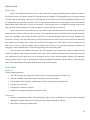
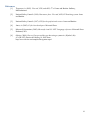
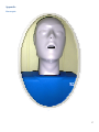
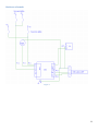
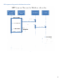
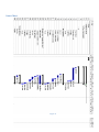
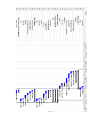
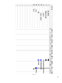
University of Puerto Rico
Department of Electrical and Computer Engineering
Mayagüez Campus
CPR Electronic Teaching Assistant Mannequin Progress Report
March 25, 2009
ICOM 5047 – Computer Engineering Project Design Course
Professors: J. Fernando Vega
Vega-Riveros,
Riveros, Nayda G. Santiago and Manuel Rodríguez
EHS team: Arelis Perez Peña, Jose A. Lombay Gonzalez, Juan C. Gorritz García,
Jomar Rosario Muñiz, Edvier Cabassa Miranda
Section –032
1
Table of Contents
List of Figures ......................................................................................................................................................... 3
Executive summary................................................................................................................................................. 3
Software .............................................................................................................................................................. 4
Hardware ............................................................................................................................................................. 4
Introduction ............................................................................................................................................................. 6
Progress Report ....................................................................................................................................................... 6
Status ................................................................................................................................................................... 6
Project Plan ......................................................................................................................................................... 7
Delays, changes and corrective Plan ............................................................................................................... 7
Tasks ................................................................................................................................................................... 7
Completed ....................................................................................................................................................... 7
In Progress ...................................................................................................................................................... 8
Next Tasks ...................................................................................................................................................... 9
Changes ............................................................................................................................................................. 12
Technical Plan ....................................................................................................................................................... 12
System architecture design ............................................................................................................................... 12
Software ............................................................................................................................................................ 12
Hardware ........................................................................................................................................................... 13
Future work ........................................................................................................................................................... 14
Phase Two ......................................................................................................................................................... 14
Phase Three ....................................................................................................................................................... 14
Software ........................................................................................................................................................ 14
Hardware ....................................................................................................................................................... 14
For the microcontroller: ................................................................................................................................ 15
References ............................................................................................................................................................. 16
Appendix ............................................................................................................................................................... 17
Mannequin .................................................................................................................................................... 17
Hardware schematic ...................................................................................................................................... 18
UML sequence diagram for database interaction ......................................................................................... 19
Software modules – Updated ............................................................................................................................ 20
Gannt Chart ....................................................................................................................................................... 22
2
List of Figures
Cost breakdown……………………………………………………………………………………………………………..11
Budget investments…………………………………………………………………………………………………………12
Mannequin…………………………………………………………………………………………………………………..17
Hardware schematic………………………………………………………………………………………………………...18
UML Sequence diagram for Database interaction…………………………………………………………….……………19
Software modules-Updated…………………………………………………………………………………………..……..20
High level……………………………………………………………………………………………………………….....20
Low level…………………………………………………………………………………………………………………..21
Gantt Chart……………………………………………………………………………………………………………….....22
List of Tables
Hardware components………………………………………………………………………………………...…11
3
Executive summary
As this document is submitted, we are currently working on the development of phase two or our project. On the
software side, much of the user interface design was completed in phase one. This gave the client an idea of what the final
product would look like. A few aesthetic modifications have been made to the design, making it easier to use, as well as
implementation modifications to make the interface simpler to use. Software issues have also materialized due to
misunderstanding conventions in the programming language, but were not so complicated as to delay the software
development. Concerning the database aspect, it has been implemented as demonstrated in the first oral exam. No
significant changes have been made.
In the hardware area, much progress has been made, even though a delay was faced in the delivery of the
mannequin. The different sensors are currently being relocated from the imitation mannequin to the real one. Creativity
has been used in the placement of the sensors in order to prevent damage to the mannequin, and care is being taken to
insure a final product that isn’t so unreal that it won’t help the student visualize what he or she could someday experience
in real life. The goal is to avoid at all costs the addition of any steps to the procedure while maintaining a functional
mannequin, since the procedure is highly dependant on a specific sequence of steps. If the student has to press a button,
for example, in order to activate a reading, he or she could become unfocused when he or she is faced with the problem in
the real world. Steps are also being taken to insure that the sensors will be held firmly in place, especially since the
mannequin will receive brute force movements through chest compressions.
Regarding the microcontroller status, we are using it as a bridge between the computer that will have the software
and the mannequin. It is using the UART to transmit the sensors outputs at a 9600 bit/sec. The sensors are all connected to
port 1 of the microcontroller, at the same time the ADC at the same port is used to connect sensors like the microphones,
force sensors and pressure sensors.
A brief summary of the deliverables for this phase are listed below:
Software
A functional prototype of the software application, now with added functionality is provided. Features include:
•
Create an account and reset password in case of loss
•
View detailed student information (name, student number, average grade, section)
•
View course information such as sections, and enrolled students in each section
•
User authentication
•
Recognition of the flags that come in through the serial port
•
Database information is accessible, manageable, and processed in the user interface
Hardware
We did not have the mannequin for our first demo. For that reason, most of our time has been used to integrate
our sensors into the mannequin. For a detailed schematic, please refer to figure 2 in the appendix. We have two push
buttons to verify if the student “pinched” the nose while providing the air to the victim. Also, we placed two push buttons
4
on the area where the student is supposed to verify the pulse of the victim. Also, there is a pressure sensor in the throat of
the mannequin to detect if the student provided air to the victim. This is detected by measuring the change of pressure
caused by the air provided from the student. We substituted the LED simulating the pulse of the victim with a buzzer that
will make a sound when the victim has been successfully resuscitated.
Regarding our estimated budget, based on the project status, we haven’t made any changes, thus no extra
purchases have been made. Making an estimate of the future expenditures, it is clear that we will come very close to
matching the estimated budget at the beginning of the project. For a more detailed budget analysis please make reference
to the budget analysis section.
5
Introduction
Our project proposal presented a challenging problem: develop an electronic teaching assistant mannequin in
order to help instructors and professors teach CPR techniques. Some of things we presented that make our project
different from similar products on the market is the comprehensive monitoring of all steps that are necessary in order to
provide correct CPR assistance (breath checking, chest compression, etc.) Also, our product would contain a graphical
user interface (GUI) developed to meet the format to manage groups and grades in a classroom in any institution. A
significant challenge of our project is also to make the product as similar as possible to an unmodified CPR mannequin,
even thought ours would contain several sensors.
Based on our proposal and the objectives set, we are focused on completing those objectives for the final
presentation. For example, in the software area, the GUI that is being developed is evolving to include classroom
management, such as the option to manage students, sections, and courses (with the ability to add, edit, and delete them).
Usability is an important factor, and a meeting has been scheduled with the client to insure that the application is as usable
as possible when it comes to keeping his or her courses organized and under control. At the moment, perhaps the most
difficult part of the software development is taking place in the live training section. The GUI has to be able to receive,
process, and display the information coming in from the sensor in an easy-to-understand manner in real time. Extra time
and dedication is being used in the development of this section, which is keeping its development on schedule so far.
In the hardware area, a CPR mannequin was purchased, and although we ran into issues with the shipping, we
finally received it. The parts are currently being transferred from the temporary mannequin, and the hardware team is
working hard to plan and customize the location of sensors in order to accomplish one of the objectives, which is to
monitor all steps of the CPR process. This customization is being done carefully in order to maintain a similar look and
feel as that of an unmodified mannequin.
This report focuses on the technical part and process of our project. We will be discussing as well as
analyzing our status with regard to the proposed timeline, clearly stating if we are on schedule or not. A critical
and sincere analysis will be done to demonstrate the critical paths of the project and how we are dealing with
difficulties and delays faced. A short budget analysis is also provided to outline expenses and identify any
changes with respect to the original budged that was estimated. A technical plan is also presented in order to
provide evidence as to the progress and implementation of the project. The report concludes with development
that will take place in the next phase based on our current status, focusing on deliverables.
Progress Report
Status
The project development is in the second phase of the CPRETAM project according to our Gantt chart. The first
phase of the project that consisted of the How to do CPR was developed about 95%, the 5% that was not completed is
because we expect some changes in the communication module for the second phase that should affect the first part. As of
6
now all tasks are on schedule; at the very least, every task issued for this phase is underway. The following metrics are
being used to determine task progress:
•
•
•
•
•
•
0% - Not started
10% - In progress
50% - Implementation done, needs testing
80% - Implemented and tested, needs verification and integration
95%-Completed but on standby for possible revision.
100% - Completed
This metric system allows us to have a general idea about the current status of the project and individual tasks.
This also measures the performance of the members of the EHS team and whether or not it is necessary to move or
reassign some task.
Project Plan
At this point of the project our team is developing the second phase that has as a deliverable for the software part
the real time training module and for hardware all the sensors need to be in place in the mannequin.
Delays, changes and corrective Plan
Considering that this project involves many tasks, the changes in the initial plan have been very few. To be exact,
2 major changes were made to our plan; the first one was that the GUI and application development for the software
department will be performed using pair programming. This allows us to have more ideas, debug in parallel with the
development, and if some researching has to be done it will not cause a delay since one member can research while the
other codes. The other issue that materialized was the delay in the mannequin shipping. We had to simulate the
mannequin to test the sensors of the first phase. We are now on time to recover the wasted time due to this materialized
risk. The mitigation of this risk was successfully implemented. Another thing that helped to mitigate this problem was that
the hardware tasks are not the critical part of the project.
Tasks
The tasks to complete the CPRETAM project was specified in the WBS and Gantt chart provided in the project
proposal. Here we will show the tasks that have been completed, the progress of the current tasks using the specified
metrics, and the next tasks that were assigned.
Completed
Software Team
Juan Gorritz – Frame handling for new database operations, some database work (integration & testing)
DB queries class: 100%
Add course/student, create account frame design: 100%
Create account (pair): 100%
How to debugging: 100%
7
Edvier Cabassa – Database queries & methods for new database operations, pair programming with
Juan
DB local setup & configuration: 100%
Create account (pair): 100%
Query to create account: 100%
Query to reset password: 100%
Jomar Rosario
UART transmission: 100%
Sensor data retrieval: 100%
Code Optimization (UART): 100%
Changes due to code review: 100%
Hardware Team
Arelis Perez & Jose Lombay
Removal of components from demo mannequin: 100%
Localization of components on new mannequin: 100%
Port identification for connections: 100%
Testing: 100%
Jomar Rosario
Testing: 100%
In Progress
Software Team
Juan Gorritz
Add course (pair): 50%
Add student (pair): 50%
Student details (pair): 50%
Live training: 10%
Edvier Cabassa
DB queries: 50%
8
Add course (pair): 50%
Add student (pair): 50%
Student details (pair): 50%
Jomar Rosario
ADC programming: (80%)
Hardware Team
Arelis Perez & Jose Lombay
Mannequin Surgery (pair): 50%
Mannequin component placement: 50%
Sound detectors configuration, interface and placement: 10%
Push button for neck position: 10%
Jomar Rosario
Mannequin Surgery (pair): (50%)
Micro-controller interface: (50%)
Next Tasks
Software Team
Juan Gorritz
Live grading
Custom grading scheme
Results report
Edvier Cabassa
Query to delete professor account
Query to delete students
Query to change grade
Results report
Jomar Rosario
UART PC-Micro
Testing
9
Hardware Team
Arelis Perez
Wireless communication
Mannequin esthetics
Force sensor configuration and placement
Jose Lombay
Wireless communication
Mannequin esthetics
Force sensor configuration, interface and placement
Testing
Jomar Rosario
Wireless communication
Mannequin esthetics
Testing
10
Budget Analysis
The budget of the project is under the estimation in the proposal. We receive the refund of the mannequin
shipping by the amount of $66.50, adjusting the budget amount of the hardware cost from $255.28 to $188.78. The
hardware components and cost are detailedd in the following table.
Component
Mannequin
Push Buttons
Sound Detector
Cable (jumpers)
Case
Rocker switch
Batteries
Miscellaneous
Total
Amount
$94.45
20.08
25.59
10.46
6.20
3.73
3.20
23.07
$188.78
Table 1
This chart show the actual cost of the hardware components and the estimated in the proposal.
400
$394.76
350
300
250
$190.00
200
$188.78
Estimated Cost
Actual Cost
150
Future expenditures
100
50
0
1
2
3
Figure 1
11
This chart shows the budget invested in the hardware part of the project and in the human resources following the time
and payment per hour stipulated in the proposal.
$188.78
Hardware
Human Resources
$16,569.80
Figure 2
We are waiting for the components needed to finish the project. There are the force sensors, the Zigbees and plug
connectors (6 males and 6 females). The total cost of these components is approximately $190.00, that when added to the
$188.78 spent does not exceed the amount stipulated in the proposal.
Changes
The only problem that changed a little bit our estimated budget was the problem with the shipping of the
mannequin. But it was resolved.
Technical Plan
System architecture design
Software
Initially, phase two was going to be dedicated solely to the live training process and the correction of minor bugs
left over from phase 1. However, due to the increasing complexity of database operations, including some processes that
were overlooked, the focus in the beginning of this phase has been changed in order to deal with the new processes.
The first important task of this phase was to modularize the database connection methods into one class,
clsConnector.cs. The class is set up to have two public methods, one for setting the search parameters and one for
connecting to the database and returning the data retrieved. The parameters sent to the class are the query to be executed
and a search index which, when sent through the method is switched to determine which internal method will be executed
for the database cycle. For example, if I were to send (“SELECT * FROM students”, 4) as the parameters, the class would
12
know to use the first parameter as the query and determine that it needs to use method 4 to get the desired data. For a more
time-based representation, please refer to the appendix, figure #2.
The next few tasks materialized when the “Create account” process was created, where the software developers
realized that processes would also have to be created to be able to add courses, sections and students. Pair programming
became necessary to complete these tasks as fast as possible in order to not fall behind in the training process, which has
been taking place in parallel with the new form creation and database manipulation. Completed tasks include the ability to
reset a forgotten password, create a new account, and retrieve student details, please refer to the appendix, figure # 3.
Bug fixes and performance issues have been corrected in this phase. The database operations have been optimized
by storing the database file on the machine and accessing it locally rather than over an internet connection, making
threading unnecessary for database interaction; however, in the interest of expansion, threading will be left in tact, in case
the user would like to use a remote server to store the data. Form handling has been changed to use the ShowDialog()
method instead of Show(), which increased the speed of the program. Several bug fixes have occurred throughout the
program, most notably in the “How to perform CPR” form, where if a user pressed the Previous button, the program
would lose its place and on most occasions, crash. Features have been added to better notify the user when the system is
waiting for a response and when he or she has done something correctly. Previously unnoticed errors in the View Courses
form have also been corrected. Students not belonging to specified sections were being retrieved, which would cause an
error when trying to view their information. The error was in one of the queries, and has been corrected.
In the live training section of the application, a class has been created to “translate” the flags into userunderstandable text. The serial port receives six flags from the microprocessor’s Zigbee device, each flag representing
whether or not the user activated one or more of the sensors. The new class identifies which flags have been activated and
generates a String which will be used to notify the user of the action that was just performed. The next step in this process
will be to test this class and create an ArrayList with the correct sequence, in which the live sequence will be compared to
determine correctness.
Hardware
As shown on the hardware schematic (Figure 2 in the appendix), we will be interfacing several sensors and
switches with the micro-controller. We will have two push buttons connected to pin P1.0, which will be used to monitor if
the student verified the pulse of the victim. Two more push buttons are connected to pin P1.3 and are being used to
determine if the student pinched the mannequin’s nose while providing air to the it. This will be done by using the
pressure sensor that is connected to the ADC pin P1.1. If the buttons are pushed while a change of pressure occurs, then
we know that the student provided air while pinching the nose. By utilizing similar logic, we will be able to detect if the
student provided air without closing the nose. A buzzer is being used to indicate if the victim was resuscitated and it is
connected to the pin P1.1 as well. As explained in our previous report, the communication to the application is being done
with a Serial to USB cable, from our micro-controller to the computer running the application. We are using three cables,
“0” for ground, “3” for receiving data from the sensors to the microcontroller, and “4” for sending data from the microcontroller.
13
Future work
Phase Two
We are in the middle of the phase two so we have some tasks in progress and others that have barely been started.
The software group will continue with the GUI and application development. The debugging process is being performing
in parallel with the developing. Code Review and Testing has to be prioritized. The insertion and deletion queries have to
be completed for this part and are in process. The serial port communication has to be tested again soon to insure that the
improvements made in the How to section are functional. The next major task is to complete the training section of the
program, which will read the data in real time and process it to determine the score achieved.
Some sensors have not been delivered yet. One of them is the sound detector that will be used to detect when the
student calls the victim to verify if he/she is conscious. The sound detector that we ordered provides an output between 0
and 5 volts, depending on the amount of sound received. We will be connecting that sensor to the ADC. Another of the
sensor that is missing is the force/load sensor. It will be placed on the torso and it will be used to measure the amount of
force applied by the student to the victim at the moment of the compressions. This connector will be connected to the
ADC as well. Since we will have multiple sensors connected to the ADC, we are currently exploring the alternative of
using logic circuit to alternate the use of the ADC depending on the sensor being used.
In the microprocessor module of the project, the ADC subroutine was completed, but it has to be adapted to each
sensor; the calibration of the sensors will be done in this code. UART communication between PC and microprocessor has
to be implemented. In the sensors part, we are waiting for the force sensor and microphones shipping. The mannequin
surgery continues until we have an aesthetically acceptable and durable mannequin with the sensors in place (damageproof). This implementation and testing should be done by the end of this phase.
Phase Three
Software
For the software application:
•
Allow the instructor to configure the evaluation process and program options (COM, IP, etc)
•
Generate an HTML report where student evaluation sessions are presented
•
GUI should be 100% functional, which means all frames are designed and implemented
•
Log and view past results
•
Non-interactive tutorials completed
•
Database file encryption for protection of sensitive data
Hardware
•
Wireless communication module, done through the Zigbee device connected to the microcontroller inside the
mannequin to another Zigbee device connected to the computer through a USB cable
•
Bug testing to insure proper functionality
14
For the microcontroller:
•
All code necessary to transmit information efficiently from the mannequin to the software
•
Demonstrate that the microcontroller is the bridge between the application and the mannequin
•
Logic implemented to transmit and receive data through the UART, only transmitting changes in the flags
Apart from the above-mentioned deliverables, a user manual will be completed for the use of the mannequin with the
software. A final report and presentation will also be delivered.
15
References
[1]
Thygerson, A. (2005). First aid, CPR, and AED, 4th ed. Jones and Bartlett: Sudbury,
Massachusettes.
[2]
National Safety Council. (1999). Heartsaver facts: First aid, AED, CPR training system. Jones
and Bartlett.
[3]
National Safety Council. (1997). CPR for the professional rescuer. Jones and Bartlett.
[4]
Jones, A. (2003). C# for Java developers. Microsoft Press.
[5]
Microsoft Corporation. (2002). Microsoft visual C# .NET: Language reference. Microsoft Press:
Redmond, WA.
[6]
Obviex. (2009). How to: Encrypt and decrypt data using a symmetric (Rijndael) Key
(C#/VB.NET). Retrieved February 10, 2009 from
http://www.obviex.com/samples/Encryption.aspx#
16
Appendix
Mannequin
Figure 3
17
Hardware schematic
Figure 4
18
UML sequence diagram for database interaction
Figure 5
19
Software modules – Updated
Figure 6a
20
Figure 6b
21
Gannt Chart
Figure 7a
22
Figure 7b
23
Figure 7c
24
Figure 7d
25