1
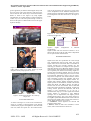
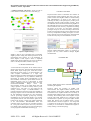
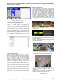
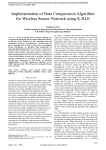
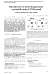
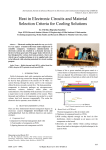
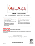
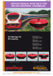
International Journal of Advanced Research in Electronics and Communication Engineering (IJARECE)
Volume 3, Issue 4, April 2014
An Innovative Design Initiative for Preventing
And Or Interrupting Carnage during Surface
Transportation.
Prof. R.N. Panda1, Dr.M.G.Tiary2, Swati Bhattacharjee3
1,2,3.Department of Electronics and Communication Engineering
Asansol Engineering College.Asansol,West Bengal,India
Abstract:- Adequate and coordinated consideration of
safety integration issues, by both the Board and the
Local Railroad Administration, are responsible for the
enforcement
of
railroad
safety
and
its
implementation.Members
of
the
Surface
Transportation Technical Group recognize that the
human operator is an integral component of a system
comprised of the operator, the surface vehicle, and the
environment. Therefore, the same effort that goes into
designing and developing the vehicle and its
infrastructure must be put into optimizing the
behaviour and performance of the operator. As the
performance capabilities of ground and rail, based
vehicles become more advanced, accompanied by equal
advances in the complexity of the operating
environments, we must ensure that vehicle handlers
are able to perform their tasks with minimal errors
and maximum comfort. Adopting a systems approach
to surface transportation security, including an
understanding of the surface transportation sector as a
complex, interconnected system of networks and
functions is mandatory. It is critical to recognize the
security measures currently in place to determine a
strategic path forward for addressing the Nation’s
surface transportation security [2]. This paper presents
a system to upgrade existing Security monitoring
systems in the trains. The goal is to design and
implement a cost effective and intelligent full-fledged
microcontroller and wireless based system to save the
lives of the passengers in a running train. This is very
low cost solution as no change is necessary to be made
to the infrastructure of the existing system. Key to
success, however, still lies in the in the method to send
distress signal to the person in charge with pin point
accuracy and speed by using available robust and state
of the art technology like ZigBee replacing age old
conventional chain pulling systems[ACP]. This project
uses ZigBee pro, communicating easily over 2 miles of
outdoor
and
being
interfaced
with
8051
microcontroller kit and LCD display can process and
communicate distress signals at great speed and
accuracy, needed for safety of the passengers[at the
flick of a button]. This is economically feasible in
contrast to that using Wi-Fi system. Main purpose of
this project is to install these modules in a train to save
the lives of the passengers on moving train and to
make safety and happy journey for the passengers.
Key word: ACP-Alarm Chain pulling; DEMU-Digel
Electrical Main line Unit, MEMU-Mainline Electric
Multiple Unit, Microcontroller, ZigBee Pro-ZigBee
professional
I.INTRODUCTION
Improvements in security activities and coordination are
needed to effectively reduce and manage risk and enhance
security within surface transportation. Inability to apply an
integrated systems management approach to assessing risk
and improving security and resilience is short-sighted and
does not fully account for a networked surface
transportation system existing in our country. Using
intelligence to identify potential threats by employing
programs and procedures that allow for better
identification and interdiction of threats prior to their
arrival. Engaging system operators in intelligence sharing,
security planning, and operations is required ensuring that
key transportation workers are vetted. Increasing frontline
worker and public security awareness; creating a more
stringent, less opportunistic environment for terrorist
attack [1] planning (e.g., non-intrusive inspection devices,
canine teams, random bag checks, etc.) and countersurveillance; changing operations to reduce vulnerabilities
and potential consequences and to thwart attempts to
circumvent security measures; hardening critical
infrastructure (e.g., intrusion detection, facility hardening,
smart Surveillance) and common operating picture
development and improving general efficiency are some
of the essential key measures to be put in place.
In the extreme cases of emergencies like fire, dacoity and
the other forms of organised crimes, passengers travelling
in high speed trains are really helpless on two grounds.
One they are unable to locate /actuate the alarm during
near stampede situations [during a fire hazard] as shown in
the figure-1, or are rendered motionless due to mortal fear.
Even if somebody gathers courage /chance to actuate the
alarm, the motorman only stops the train to investigate the
cause and its location by an elaborate search operation. By
the time anybody checks in the compartment of distress,
most of the damages are already done and the dacoits will
431
ISSN: 2278 – 909X
All Rights Reserved © 2014 IJARECE
International Journal of Advanced Research in Electronics and Communication Engineering (IJARECE)
Volume 3, Issue 4, April 2014
get the opportunity to dismount and disappear easily from
the scene of the crime. Irate passengers will wait for the
train to reach the next station only to surround the Station
Master as shown in the figure-2. By using ZigBee
communication at 2.4GHz, situations could be handled in
a better way even if the train speeds through a tunnel as
shown in the figuure-3. Method will be clear as this paper
sequences through.
receiver unit powered by the 135Volt AC power source
of the compartment and an additional arrangement for
standby operation with battery bank beneath the carriage.
The arrangement looks like that shown in the figure -5
below.
Figure-4: A train moving over an embankment.
Courtsey-Google.com
¥ZN
¥ ZN-1
¥Z0
Figure-1: Fire in an AC Coach. Coursey-Google.com
CN
CC
CN-1
.........................
C0
Figure-5:
ZigBee
configurations
in
different
compartments.
ZigBee module with the microwave antenna is to be
fitted on the top left on the rear side of each compartment
for free space instant communication.
III.ZIGBEE TECHNOLOGY
Figure-2: Tanusree Sil recounts at Howrah station how a
robber held a pistol to her head. Picture by Gopal
Senapati.Courtsey-Telegraph-Dec-20, 2013
Figure-3: Tunnel of Pir Panjal in J.K, Courtesy Google.com
II.SYSTEM APPROACH
As shown in the figure -4, a train can be considered as a
cluster of a number of microcontroller cards housing
communication program and ZigBee-Pro unit fitted with
each card, which can operate as a self contained trans-
ZigBee is the name of a specification for a suite of high
level communication protocol using small, low power
digital radios based on the IEEE 802.15.4 standard for
wireless personal area networks (WPANs) [4]. The
technology is intended to be simpler and less expensive
than other WPANs, such as Bluetooth. ZigBee is used for
radio-frequency (RF) applications that require a low data
rate, long battery life, and secure networking. ZigBee is a
wireless mesh networking standard. The low cost allows
the technology to be widely deployed in wireless control
and monitoring applications, where as the low powerusage allows longer life with smaller batteries, and the
mesh networking provides high reliability and larger
range of communication[4]. The ZigBee Alliance is a
standard body defining ZigBee operational protocols.
ZigBee operates in the industrial, scientific and medical
(ISM) radio bands- 868 MHz in Europe, 915 MHz in
countries such as USA and Australia, and 2.4 GHz ISM
band in most other jurisdictions worldwide. Compared to
existing wireless protocols like Bluetooth, and Wi-Fi
ZigBee is more advantageous as we can get a
communication range up to 1.6 km. ZigBee has excellent
security features as encryption is used. Different
topologies can be implemented with ZigBee protocol
including mesh topology, peer to peer shown in figure-6.
The ZigBee specification identifies three kinds of devices
that incorporate ZigBee radios, with all three found in a
typical ZigBee Network are given below.
1. Coordinator, which organizes the network and
maintains routing, tables.
2. Routers, which can talk to the coordinator, to other
routers, and to reduced function end devices
432
ISSN: 2278 – 909X
All Rights Reserved © 2014 IJARECE
International Journal of Advanced Research in Electronics and Communication Engineering (IJARECE)
Volume 3, Issue 4, April 2014
3. Reduced function end devices, which can talk to
routers and the coordinator, but not to each other [6].
Figure-6: ZigBee Mesh Network [6]
Figure-7: ZigBee stack[5]
ZigBee is built on top of the IEEE 802.15.4 standard.
ZigBee provides routing and multi-hop functions to the
packet-based radio protocol. It is the foundation on
which ZigBee is built. Figure-7 Shows a simplified
ZigBee stack, which includes the two layers, specified by
802.15.4 the Physical (PHY) and MAC layers [5].
V.DESIGN CONCEPTS
Proposed model consists of minimum two numbers of
microcontroller boards interfaced with LCD, some low
profile switches and a ZigBee module in each facilitating
data communication, as shown in the figure-8 for
enhancing the safety of the passengers by averting if not
interrupting tragedies inside speeding carriages. These
self sufficient microcontroller boards housing ZigBee act
like individual trans-receiver modules and these modules
can be installed in each and every compartment including
the engine of the train. So that during emergency
passengers can press one switch according to their needs
and the corresponding message will be displayed in each
and every compartment including the engine of a train.
Then it becomes clear for all passengers- what happened
and the necessary helps can be mobilized in no time.
Figure-8: shows two almost identical modules capable
alternate SEND RRECEIVE modes of operation by
program and key board initiation through ZigBee
communication
VI.HARDWARE
5.0V
IV.MICROCONTROLLER
A microcontroller incorporates all the features that are
found in microprocessor. The microcontroller has built in
ROM, RAM, Input Output ports, Serial Port, timers,
interrupts and clock circuit [7]. A microcontroller is an
entire computer manufactured on a single chip.
Microcontrollers are usually dedicated devices embedded
within an application. It is very difficult to disable [by
miscreants] an in-built digital communication by the
microcontroller activated by a quick feather touch on an
illuminated switch, since it is inaccessible .It works
silently, instantaneously and decisively and in error free
manner.P89C51RD2BN
Philips
made
8-bit
microcontroller, because of its CMOS design and wide
voltage operation, is useful for battery and AC power
operations for a long time. It is best suited for the
existing electrical setups of MEMUs/DEMUs. Its
powerful instruction repertoire provides true flexibility in
designing compact error free communication subroutines
for this demanding environment. Its open architecture
and bit processing capability greatly help bit-string
manipulations [3]. This controller board is very versatile
and operable from the lead acid batteries placed at the
bottom of the carriage. Unique open ended architecture
of the microcontroller P89C51RD2BN make this
controller board very effective for networked operation
for a long time without system chaos. Key board and
LCD display allow inputting of user data and debugging
of new programs and attachment interfacing [3].
Computer
RS-232
Microcontroller
LCD&KEYPAD
ZigBee
5V to 3.3V
Converter
Figure-9: Block Diagram of the individual trans-receiver
unit during development.
Figure-10 Shows the interface of ZigBee with
microcontroller. The ZigBee modules works at the 2.4
GHz frequency which means smaller embedded board
and antenna in size. ZigBee modules have the ability to
transmit Digital, PWM, Analog or Serial RS232 signals
wirelessly. For interfacing 8051 with a ZigBee we just
need the TxD, RxD, GND and Vcc connections. Data
communication is possible by using the ZigBee module
digital data directly into the SBUF register of 8051
microcontroller as shown in figure-10. +5V and ground
is connected to provide power to the module. While TX
and RX pin is connected for communication.ZigBee is
mainly working in the mesh topology.
433
ISSN: 2278 – 909X
All Rights Reserved © 2014 IJARECE
International Journal of Advanced Research in Electronics and Communication Engineering (IJARECE)
Volume 3, Issue 4, April 2014
train accesses the situation quickly and starts acting
correctly in the present circumstances and sends armed
personnel the scene of the crime through the common
corridor in case of robbery.
Microcontroller board senses the keys all the time till a
valid key closure is identified; it then sends a character
string to all the other controllers in the vicinity through
its own ZigBee and informs the exact danger and
location by the sent information packet. Other
microcontrollers receive these packets to decode the
danger massage and location of it for its own in-house
display. Controller in the driver’s cabin will facilitate to
inform the sender that the message is received and help is
on its way through a keypad initiation to the great relief
of the passengers in distress. Motor man will then start
multiple activities like speeding/breaking the train,
asking for further help and reinforcements from the
nearest centres to ensure a tragedy interruption if not
averted fully.
5V to 3.3V
Figure-10: Circuit Diagram of the Proposed System
To establish a mesh topology in railway network using
ZigBee Communication is also a very challenging and
purposeful application. For constructing such kind of
network, self-contained microcontroller board interfacing
with ZigBee module, LCD, and some illuminated
switches, is placed in each and every compartment
including the Engine of the train in distributed manner
near passenger berths as shown in the figure-11.
Components of communication hardware are shown in
the figure-12.
Fire
Dacoity
Fighting
Heart attack
Murder
Crime on
Women
Figure-11: Emergency switches are located near the
berths of the passengers.
(a) Message received in the driver,s cabin
(b) Test message sent to the caller
Fuger-13:Typical interchange of test messages.
Figure -13 shows how messages are echoed back to the
distressed caller from the motorman’s cabin. Motor man
of the speeding train can send armed force to the
distressed compartment through the common corridors
from both sides and also initiate rushing of fire
extinguishers to the compartment in fire after slamming
the break, as the situation warrants.
VIII.SOFTWARE DEVELOPMENT
(a) Microcontroller board
(b) ZigBee Board [8]
Figure-12: Communication hardware.
VII.COMMUNICATION AND CONTROL
Otherwise peaceful and comfortable journey of the
passengers of a high speed train can suddenly turn out to
be a miserable one when the just joined passengers flash
out a gun and start demanding money and jewellery or
smokes bellows out from the adjacent joints of the
carriage. In this case any passenger can push the right
kind of feather touch switch to inform the motorman and
passengers of all other compartments about the danger
within split second and with deadly accuracy.
Microcontroller senses the switch closure and relays the
information through the ZigBee to all the compartments
including Driver and the TTE. Motorman of the speeding
1. Virtual Programmer. Development microcontroller
board is connected to a PC using a serial cable. Program
is developed using the development tools and is written
into the memory of the microcontroller on the
development board. The board has the facility of insystem programming [9]. We can download or erase the
program on board without using any programmer device
or even without removing the chip from its socket. This
will avoid the damage to the chip as well as it will be
very easy to proceed on program development. To
download the programs to the board a virtual program
utility (WINISP) package is pressed into the operation
environment. This utility is from Philips and supports a
number of on board microcontrollers of the same family.
The screen shot in the figure-14 shows the features of the
WINISP utility program.
434
ISSN: 2278 – 909X
All Rights Reserved © 2014 IJARECE
International Journal of Advanced Research in Electronics and Communication Engineering (IJARECE)
Volume 3, Issue 4, April 2014
2. ZigBee communication.
Two microcontroller boards tested [as above] with the
programs loaded in the memory of 8051 were interfaced
with the ZigBee modules with appropriate connections of
TxD ,RxD, Vcc and Ground as shown in the Figure-10
and switched on to establish wireless communication
between them. Wireless communication is the fastest and
safest way of communication unlike wire connections
which are susceptible to EMI present in the electrical
wirings of MEMU and DEMUs. ZigBee option is low
cost technology and can be consider as a mini WI-FI
connectivity without massive infrastructural investments.
Figure-14: WINISP Screen shot
2. Virtual Programming Builder (VPB)
This is a software tool which provides facility to write a
program in assembly language. Programming was
decided to be written in the assembly language. This
enabled us to write compact general purpose and multiple
nestable programs for efficient utilization of memory
space. Integrating various utility modules in future will
become easy. This package converts assembly language
program in hex codes which can be loaded into the
development board using WINISP that creates four types
of files on assembly programs these are .HEX files, .BIN
files, .ASM files and .PRN files. The screen shot of the
VPB software is shown in the figure.-15 below.
Figure-16: Two
communication
development
(a)
boards
in
wired
(b)
(a) Eco from reception after transmission (b) Pulse shape
of transmitted character.
Figure-17: Message and pulse shape during continuous
transmission and reception.
Figure-15: Program development screen in VPB
IX.TEST METHODOLOGY
1. Two wire communication.
Before interfacing ZigBee modules with two
microcontroller development boards we have configured
them as two trans-receiver units communicating through
two wire connections. While the serial transmission
program was being put in endless loop, a serial pulse
train for transmission and reception of a specific ASCII
character was visible on a CRO screen and also the
ASCII character is display on the LCD whenever the
respective switch will be pressed as shown in the figure16 and Figure-17 below. Here CRO is used for testing
purpose for ensuring that the boards are able to transmit
and receive various ASCII characters accurately .For
example after pressing the right switch of board-1, it is
able to transmit and display an ASCII character A. After
receiving A, the board-2 will transmit another ASCII
character say U when the required key switch is pressed
on the board in question.
(a) Two test boards interfaced with ZigBee are
communicating (Photocopy of Actual Design Circuit)
(b) Communicating ZigBees are placed side by side
Figure-18:
Showing
ZigBee
setups
during
communication
Figure-18 shows how the boards were initialised into a
closed loop communications in the laboratory.
X.TEST RESULTS
435
ISSN: 2278 – 909X
All Rights Reserved © 2014 IJARECE
International Journal of Advanced Research in Electronics and Communication Engineering (IJARECE)
Volume 3, Issue 4, April 2014
ZigBee communications were carried out in different
laboratory set ups and with different personnel including
corridors for ascertaining the effect of environment on
secured ZigBee communications. Results are summarised
on the table-I below.
Table-I Test Results
Serial
No.
Distance(In
door
Range)
1.
7 meters
Laboratory
Observations
Solid
lab
Properly
Receive
and
Transmit Data
Send –Receive
Ok through the
glass panel.
Working
Properly
Working
Properly.
The design outlined above will enable us to install these
modules in a train to save the lives of the passengers on
moving train and to make the travel a ZERO HARM
proposition for the vast millions. The security of the
women in a moving train can be increased to a point well
above the present scenario. Incidence of pick-pocketing,
theft or looting etc. will, we believe, drastically come
down to a low level when all aspects of security as
discussed earlier are put in place.
XII.FUTURE WORK
state
2.
11meters
3.
16 meters
Solid state
and Digital
Lab
Basic Lab
4.
35 meters
Corridor
Prototypes are developed successfully and are awaiting
field trials and testing in MEMUS/DEMUs.
This project opens up immense possibilities like safety
communications, processing of distress signals from
vehicles, short robotics movement through ZigBee
networks for attending places which are otherwise
beyond human access- like chemical warfare zones,
nuclear warfare etc This can be commanded and
governed successfully in many areas including terrorist
activities. This being a low cost solution is very helpful
and can be adopted in numerous exploration and mining
activities in our country.
XIII.ACKNOWLEDGEMENT
The authors wish to acknowledge the helps and
continuous encouragements received from the Dean PG
studies and Research –Dr.A.K.Ganguly and Principle Dr. Bijay Krishna De of Asansol Engineering College.
XIV.REFERENCE
Figure-19: Covering a Range up to 35 Meters in our
College Campus Corridor-Block, 2nd floor-ECE Dept.
XI.CONCLUSION
For availing the comfort and benefit of Wi-Fi guided rail,
we may have to wait for a decade or more considering
the requirement of massive investment in this
infrastructure. ZigBee, however, on the other hand, is a
low cost option and bring us the benefit of safety by its
secure, speedy and accurate communication capability
being nearest to Wi-Fi. This project describes in short a
sustainable method for uplifting passengers’ safety
without much Engineering modifications on the existing
MEMUs/DEMUs’s electrical setups.
[1]Antiterrorism security and surface transportation
systems’-by
A.
Camille
N.Y.Fink;
http://www.resources.metapress.com/pdf-preview.
[2] Surface transportation security priority assessment.
http://www.whitehouse.gov/sites/default/files/rss_vie
[3] Improvised Microcontroller Networking Alleviates
Safety Hazards in Rail Journey; R.N.Panda, Prajit Paul,
Dr.A.Kumar
[4] http://en.wikipedia.org/wiki/ZigBee
[5]Product Manual on an Introduction to ZigBee
(Dynamic C)
[6] PDF on ZigBee Wireless Transceiver Engineering
Options
[7] BOOK-The 8051 Microcontroller and Embedded
Systems by Muhammad Ali Mazidi and Janice Gillispie
Mazidi
[8] http://www.rhydolabz.com
[9]User’s Manual of Edutech System
436
ISSN: 2278 – 909X
All Rights Reserved © 2014 IJARECE