1
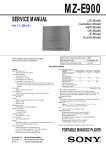
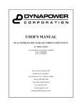
HIG 5.5 Power Supply User’s Manual P/N: HFP-7-P0102A325 October 2012 ©2012 High Frequency Power LLC dba ‘iTherm Technologies’ To ensure years of dependable service, iTherm Technologies products are thoroughly tested. Please read this manual prior to applying power to the power supply in order to operate the induction system safely and to avoid personal injury or death. All parts and labor carry our standard 1-year warranty. Additional information about the Terms and Conditions of Sale are listed in iTherm’s quotation sent to your procurement office. CONTACT INFORMATION: iTherm Technologies 85 Meadowland Drive South Burlington, VT 05403 www.iTherm.com For customer service: Toll free USA: 1.802.862.9976 Int’l: +1.802.862.9976 Fax: 1.802.864.3782 All rights reserved. Printed in the United States of America. This manual is supplied to enable the reader to safely install and operate the equipment described herein. In the interest of providing even better equipment iTherm Technologies reserves the right to make product changes without notification or obligation. RETURNING UNITS FOR REPAIR Prior to returning any unit for repair or replacement contact iTherm Technologies to determine if the problem can be resolved without returning the unit. All consults of this nature are available free of charge. Be able to provide the serial number of the unit and a description of the problem. It is important to obtain an RMA number from iTherm Technologies prior to returning any product. This process enables appropriate follow up and rapid resolution. To obtain an RMA please contact: Mark Poulin Toll free USA: 1.802.652.1321 Int’l: +1.802.652.1321 [email protected] ©2012 High Frequency Power LLC dba ‘iTherm Technologies’ Page 1 of 10 WARNING SAFE OPERATION PROCEEDURES AND PROPER USE OF THE EQUIPMENT ARE THE RESPONSIBILITY OF THE USER OF THIS SYSTEM. Symbols Used In This Manual: This symbol indicates a safety warning that requires special attention. This symbol indicates a potential hazard to personnel or property. iTherm Technologies provides information on its product and associated hazards, but is assumes no responsibility for the after-sale operation of the equipment or the safety practices of the owner or user. This equipment produces potentially lethal high-voltage, high current, high frequency (HF) energy. You should read this manual and understand its content before you attempt to power or operate the equipment it describes. Follow all safety precautions. Never defeat interlocks or grounds. THERE ARE NO USER SERVICEABLE PARTS IN THIS POWER SUPPLY. DO NOT OPEN THIS UNIT. CALL ITHERM TO HELP YOU WITH ANY TROUBLESHOOTING OR IF YOU HAVE ANY QUESTIONS AT NO CHARGE. ©2012 High Frequency Power LLC dba ‘iTherm Technologies’ Page 2 of 10 POWER SUPPLY PARAMETERS INPUT VOLTAGE: 240 VAC ± 10% 50/60 Hz Single Phase INPUT CURRENT: 20 A INPUT PROTECTION: Circuit Breaker, 20A Fuse, 250V 1A Slow Blow (for cooling fans) OUTPUT POWER: 5000W at maximum, 900V peak Note: Maximum power depends upon coil parameters. CAUTION: USE ONLY COIL HF CONNECTORS SUPPLIED BY ITHERM TECHNOLOGIES IN ORDER TO ASSURE PROPER SAFETY RATING AND PERSONNEL SAFETY. OUTPUT FREQUENCY: 36-500kHz (contact iTherm for alternative configurations) COOLING: This unit is air cooled with an air intake on the front of the power supply. Do not restrict the airflow to the power supply. Provide 3-4” clearance at the front and rear of the power supply to allow air to sufficiently enter and exit from the unit. Environmental Protection: IP 31 This equipment requires a connection to earth ground. Failure to connect earth ground will result in a potentially hazardous condition. COIL PARAMETERS COIL INDUCTANCE: 0.6 μH – 340 μH CAUTION: THE COIL MUST BE APPROPRIATELY ELECTRICALLY INSULATED FROM CONTACT. The coil carries high frequency, high voltage, high current and may present a shock hazard. Contact with the coil is not permissible. Any conductive objects contacting the coil and/or coil housing should be properly connected to an earth safety ground. ©2012 High Frequency Power LLC dba ‘iTherm Technologies’ Page 3 of 10 INTERFACE Figure 1 Front panel Figure 2 Rear panel ©2012 High Frequency Power LLC dba ‘iTherm Technologies’ Page 4 of 10 POWER SUPPLY OPERATION Connecting a Coil Care must be taken when connecting and disconnecting a coil from the power supply. Always disconnect the power supply from the supply voltage before connecting or disconnecting a coil. To disconnect the power supply from the supply voltage move the dial switch on the front panel to the OFF position. Modes of Operation This unit supports three modes of operation: temperature, time and power. The LED indicator lights on the front panel indicate the general status of the power supply Mode Green Yellow Red Time Running Standby Error Temperature Running at temp Running, not at temp Error Power Standby Error Running Custom run modes are available, contact iTherm Technologies for details. Push the mode button on the front panel to cycle through modes. Modes cannot be changed while the power supply is running. The power supply will automatically adjust to every coil connected. Temperature Mode Temperature mode operates in closed-loop control, the power supply will modulate its output power to achieve and maintain the set temperature. The standard feedback input is an ungrounded K-Type thermocouple, or infrared thermocouple with K-Type output. Custom options are available. Contact iTherm Technologies for details. Push the mode button until temperature mode is reached. Use the ↑(up) and ↓ (down) arrows to enter the desired temperature, o To toggle between °C or °F push and hold the up and down arrows simultaneously Once the desired set point is entered push the I/O button to turn the power on. Push the I/O button again to stop the output of the power supply. ©2012 High Frequency Power LLC dba ‘iTherm Technologies’ Page 5 of 10 Power Mode Power mode operates in open loop control. A power is entered on the front panel by pushing the mode button until power mode is reached. Once at power mode use the ↑(up) and ↓ (down) arrows to select the desired power in Watts. Push the I/O button to turn on the output of the power supply, push the I/O button again to turn off the output of the power supply. o NOTE: If after pushing start the power supply shows a lower than entered set power, this is the maximum power attainable with that particular coil under the present conditions. You must push I/O again to accept the new power level. To turn the output off push the I/O button. Time Mode Time mode operates the same as power mode, but will only leave the output on for a finite amount of time. First enter a set power in power mode Then push the mode button to reach time mode. Use the ↑(up) and ↓ (down) to enter the desired run time with a resolution of 100 ms. Push I/O to turn the output on. To turn the output off prior to the timer expiring push the I/O button. Analog Mode Analog mode offers a way to control the power level or temperature set-point using a 0-5V DC signal connected to I/O pins 5 & 6 on the rear panel. To enter analog mode, simultaneously press and hold both the up and down arrows for at least 5 seconds while in temperature or power mode. The machine will confirm analog mode by displaying ‘ANALOG INPUT’ on the bottom line. Once in analog mode, the power set-point in either power mode or time mode is determined from the DC value at the I/O pins, 0V corresponding to 0W and 5V corresponding to 5000W. In temperature mode 0V corresponds to 0°C and 5V corresponds to 700°C. Analog mode will remain operational even when the mode button or power switch is cycled. To exit analog mode simultaneously press and hold both the up and down arrows for at least 5 seconds in either power or temperature mode. NOTE: Exceeding 5V on the I/O pins will not result in a higher power or higher temperature set-point and may damage the power supply. ©2012 High Frequency Power LLC dba ‘iTherm Technologies’ Page 6 of 10 PROGRAMMING THE POWER SUPPLY To reprogram your HIG power supply: 1. Disconnect the power supply from the supply voltage by moving the rocker switch on the rear panel to the off position. 2. Connect a RS-232 cable from the host computer to the RS-232 port on the back of the power supply. 3. In the folder called ‘BootLoader_HostApplication’ locate and edit (with notepad) boot.bat it should only contain the following: "16-Bit Flash Programmer.exe" -i COMx -b 9600 s3.hex a. Change the x after COM to the communication port you have connected the RS-232 cable to. b. Save and close this file. 4. While the power supply is still off push and hold the I/O button. 5. While holding the I/O button move the rocker switch on the rear panel to the on position 6. Now double click boot.bat. 7. A DOS window will open and indicate the status of the programming. 8. Once the DOS programming window disappears release the I/O button, turn the power supply off and then back on again. Troubleshooting: If the boot loader returns any errors it is likely because the communications cable is not connected to the power supply and the computer, and/or the wrong communication port was specified. ©2012 High Frequency Power LLC dba ‘iTherm Technologies’ Page 7 of 10 T/C & INPUT OUTPUT (I/O) CONNECTORS: K-Type thermocouples can be attached to the connector ports TC1 and TC2 at the rear of the power supply. For North American style, attach the red lead to the minus (-) and the yellow lead to the plus (+). Unless otherwise necessary, utilize the TC1 port. I/O pins 1 and 2 provide a normally closed relay connector, opening upon any error internal to the power supply. I/O pins 3 and 4 are used for analog operation (please see page 6 for details on running in analog mode). Ensure that DC- is connected to pin 3 and DC+ is connected to pin 4. Do not exceed 5V across these pins or the power supply could become damaged. I/O pins 5 and 6 provide a normally open safety relay that closes when current is flowing through the coil. This usually occurs when the power supply is running but will also occur during the load detect cycle that produces an invalid load error. I/O pins 7 and 8 provide a means to communicate to the power supply. Typically this is utilized for turning the power supply on in a timed cycle. These pins will activate the programmed event from the front panel when pin 7 is shorted to pin 8. The heating cycle will start upon the falling edge of the signal pulse. NOTE: Contact iTherm engineering to request custom operation if the I/O pins do not provide suitable flexibility for your application. Maintenance Air Filter The air filter on the front of the power supply should be cleaned once a month or more depending upon environmental conditions. To clean the air filter: 1. Turn the power supply off. 2. Remove the plastic grommet around the air filter on the front panel. 3. Remove the filter and vacuum thoroughly, replace if necessary. 4. Replace the clean filter and re-insert the plastic grommet. 5. Reconnect the power supply for normal operation. Replacing the Fuse The fuse holder for the cooling fans is located at the rear of the power supply. Ensure the power supply is OFF when replacing the fuse. To open the fuse holder turn the fuseholder knob counter-clockwise ¼ turn. Remove and discard the blown fuse. Replace only with a slow-blow 1A 250 VAC rated fuse, the fuse size is a 20mm x 5mm package. ©2012 High Frequency Power LLC dba ‘iTherm Technologies’ Page 8 of 10 POWER SUPPLY DIAGNOSTICS The following text describes possible errors the power supply may output during its operation. Error Description Solution “ERROR INVALID LOAD” A coil with too low or too high of an inductance is connected to the power supply. This error will also occur if the coil becomes shorted. Consider adding/removing turns and check the coil for damage. “ERROR INTERNAL OVERHEAT” This occurs when components internal to the power supply approach their maximum operating temperature. The power supply will not operate until the power supply has cooled to an acceptable temperature. Check fans for operation, reduce power settings and/or move to a cooler environment. Check air filters on bottom of the power supply, clean if needed. “ERROR CONNECT COIL” This indicates that a coil is not plugged into the output of the power supply, or the coil has suffered an open circuit failure. Check coil connection and coil continuity. No lights or power No power Turn on main disconnect and check source voltage. Blank screen and LED light(s) illuminated Partial reset of microcontroller Cycle power supply main disconnect switch ©2012 High Frequency Power LLC dba ‘iTherm Technologies’ Page 9 of 10 PHOTO OF PRODUCT Mains Plug Type: NEMA L6-20 ©2012 High Frequency Power LLC dba ‘iTherm Technologies’ Page 10 of 10