1
IPSO FACTO
ISSUE
'4
JANUARY, 1978
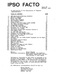
TABLE OF CONTENTS
1
2
3
4
5
6
7
8
9
10
11
12
13
14
15
16
17
18
19
20
EDITOR'S REMARKS
OUTLINE OF A TEXT EDITOR
ECONOMICAL HEX DISPLAY
A MONITOR FOR ASCII KEYBOARD AND DISPLAY
LETTERS TO THE EDITOR
MEMORY MAPPED I/O
± J2 VOLTS ON TEKATCH BUS
MEMORY TEST ROUTINE
OTHER CLUB NEWSLETIERS
RANDOM NUMBER GENERATION
ROM OUT OF RAM
ITEMS FOR SALE
ANOTHER KEYBOARD APPROACH
INTERRUPT PROCESSING ON THE 1802
ERRATIA
TEe-EDITOR DIS-ASSEMBLED
SOME NOTES ON CONNECTING AN 1861 TO A TV
MINUTES OF THE LAST A.C.E. MEETING
1802 INFORMATION SHEET
CHANGE OF ADDRESS AND MEMBERSHIP FORM
Editor
Invaluable Assistants
I
I
2
3
9
10
J1
J5
19
20
23
23
25
25
26
28
29
31
33
34
35
37
Tom Crawford
Wayne Bowdish and all
contributors to this issue.
All Newsletter correspondence should be senttol
Tom Crawford
50 Brentwood Dr.ive
Stoney Creek, Ontario
CANADA
L8G 2W8
We wish to express our thanks to Xerox Corporation and
to Dominion Foundries and Steel Co. Ltd. for their
assistance in the printing of this issue of IPSO FACTO.
(I)
EDIIORIS
REMARKS
FEB. 4. 1918
We have received many comments in the past month concerning Issues 2 and 3 of IPSO FACTO. I am pleased to say· that almost
all of the reader feedback has been favourable (I person, though,
thinks our Newsletter is too big!)
The last club mieting, held on January 10th, saw several
items discussed with great interest. Members are getting tired of
watching their console lights flash, and entering machine language
programs 1/2 byte at a time on a hex keypad. They are starting to
think seriously about running high-level languages, and the hardware system nescessary to support them.
Tho prime consideration now is to pick up an alpha-numeric
keyboard and display. To this end, several members will be investigating the availability and price of surplus and used video generators, Teletypes (Baudot and Ascii), and keyboards. We hope to
hear from them at the next meeting on February 9th.
We will also be having a flea market at the February 9th
meeting, and if it proves successful, we will probably set it up
as a monthly a~fair. So bring any items you are tired of, and some
one will probably bUy them from you. There is no dealerJs fee
charged by the club.
We have scheduled club meetings and tutorials for the next
4 months. You will find a copy of the schedule at the end of the
Minutes of the last club meeting, in this issue of IPSO FACTO~ If
you arenJt sure where the Stelco auditorium is, call one of the
Ex~cutive for directions.
One article that everyone should read can be found on pgs.
30-33 of the October 1971 issue (#19) of DR. DOBS-IS JOURNAL, or on
pgs. 65-69 in the February 1918 issue of POPULAR ELECTRONICS. The
article is by Edward M. McCormick, and deals with several items of
simple hardware and software for the 1802.
In early January I received a copy of Ross WirthJs Booklet
of Software for the 1802, in which IPSO FACTO and several clUb
members are listed as sources of significant software. In addition
Ross will be passing on any further software he receives to us in
the form of articles for IPSo FACTO.
For those who cnnot attend club meetings in Hamilton,' but
would like to get in touch With clUb members living in their area,
I suggest you write me a flLetter of Contact- for inclusion in the
Letters to the Editor section of IPSO FACTO. Simply state the geographic area you live in, and include your name, address and phone
number. For example, you might live in Ottawa, and would be interested in getting together with any members who live within your
local telephone calling area.
Incidently, I would like to point out that the "Tektron
Newsletter Issue #l fl is Issue #1 of IPSO FACTO before it was called IPSO FACTO. The name "Tektron Newsletter is no longer in use.
One very interesting source of software for the 1802 can
be found in RCAls UserJs Manual for their VIP home micro~computer.
This is a computer based on the 1802 chip combined with an 1861
Video display chip. The software I have seen shows an (~erating
System for hex keypad in 512 bytes of memory, and a 512 byte Interpreter program to allow use of RCAls IICHIP-8·11 high-level language. There are also 20 sample game programs to get you started in
CHIP-8. A very interesting package for those of you With an 1861
chip~ Check with your local RCA dealer.
i
(2)
"
A TEXT EDITOR
Wayne Bowdish
The editor of IPSO FACTO has asked me to write an article on a
text editor which I have been working on. This program would allow
you to create ASCII text files for Input t6 a ~esldent assembler
or:compiler or data files.
I think that about 2K bytes of memory
woUld be required for the editor. With the large memory board (soon
to come I hear > and a good cassette Interface this program would
provide a very useful function.
I have decided to write the article in the form of a users
manual (although somewhat shortened for publication purposes); If
there is any interest I will write some future articles describing
some ideas on implementing the editor.
FILES
EDITR views a file as a series of lines of ASCII characters •
A line is terminated by a carriage return and line feed. Each line
begins With a I to 5 digit line number in the range of I to 32767
( 32k >. Note that a line number may have leading zeros which are
ignored by EDITR. A line may consist of up to 80 ASCII characters
( including the line number but not the carriage return line feed
sequence, Ie. the line could actually be up to 82 ASCII characters
in length >.
COMMANDS
The EDITR commands are described in this section. They will be
listed in alphabetic order. Certain conventions have be adopted in
this section.
<return>
k ,
m, n
represents pressing the carriage return key. This
key is usually labled RETURN, RTN or CR •
The lower case letters "k", "m'" , and "n" are used
to represent line numbers in the range 1 to 32767
( 32k i.
inc
This represents a line number increment. Increments
may be in the range 1 to 32767 ( 32k >.
<text>
represents a string of ASCII characters which the
user types in. The string may not contain line faed
or carrige return characters since these are used
as end of line indicators.
The underscore character will be used to indicate
a space character where spaces are required. Spaces
are used to separate commands from their arguments
and to separate multiple arguments.
NOTE in all cases if line number k and line number m are specified
line number k must be less than or equal to line number m •
( 3)
C - Copy specified lines into new location
The general form of the copy command is'
C_k_m-n_inc <return>
This command copies lines k through m to a new location
starting at line number n and incrementing the new line
numbers by inc. If inc is not. present the standard default
of 10 is assumed. Lines k through m are not altered. There
must not be any lines with line numbers betwp.en n and the
largest line number created by the copy operation.
ex. if the user wanted a copy of lines 3, 4, and 5 at line
number 100; 110, and 120 the command
C 3 5 100 10
would be used. The file now contains lines 3,4;5,'100,
JIO, and 120. Note that in this example the inc value
of 10 was not required since the default value for an
increment is 10. Ie. the command could have been
C 3 5 100
D - De 1e t e Ii nes
The general form of the delete command is'
This command deletes all lines from line number k through
line number m inclusive. If m is not specified then only
line k is deleted. Lines which are deleted are effectively
removed from the file and may not be recovered.
ex.
D 3 9
D 77
delete lines 3 through 9 inclusive
delete line 77
G - Get file from cassette
The general form of the get command is'
G <return>
This command reads the next file from the cassette unit
into the program bU.ffer for editing. Further definition of
the format of tape data will be required before the format
of this command can be completely defined.
(4)
I - Insert lines
The general form of this command iSI
I_k_<text> <return>
•
This command inserts the specified line <text> into the
fIle at line number k • If line k exists when an insertion
is attempted an error message is typed •
ex.
I 55 THIS IS LINE 55
line number 55 Is added to
the file
M - Move lines to new location
the general form of the move command isl
M-k_m_n_inc <return>
This command move lines k through m to a new location in
the file starting at line number n and incremented by inc.
The original lines k through m are then deleted from the
fIle. If inc is ommited the the standard default increment
of 10 is used. In order to move only t lin~ k and m should
be set equal.
N - reNumber lines
The general form of the renumber command iSI
N_inc <return>
This command will renumber all of the lines currently in
the file. The first line will have line number Inc and the
successive line numbers will be incremented by inc. If inc
is not specified the the first line will be line number 10
and the default increment of 10 will be used.
ex. If the user has a file containing lines 97 , 105
213 the commandl
N 100
would renumber the lines to 100 , 200 , and 300.
command
N
would renumber the lines to 10 , 20 , and 30 •
(5)
,
and
The
P - Put file on cassette
The general form of the put command iSI
P <return>
This command will write the file currently in the editers
buffer onto the cassette unit. Further definition of the
format of data on the tape will be required before the P
command can be further defined.
R - Replace an existing line
The general form of this command iSI
R k <text> <return>
This command is used to replace an existing line in the
file. This command may be thought of as performing a Delete
command (D k) followed immediatly by an Insert command
( I k <text> i,
ex.
R 34 NEW LINE 34
!delete line 34 if it was
!in the file and insert
!the new text
5 - Scratch current file
The general form of this command iSI
S <return>
This command deletes all lines in the editors buffer and
initializes the editor. This command would be used if the
user was editing,several files in 1 editing session. After
each file had been ed ited and saved on the cassette tape
an S command would be issued to initialize the editor for
the next file.
(6)
T - Type lines on output device
The general form of the type command iSI
This command types the specified lines of the file on the
users output device. If both k and m are given then lines
1 through m inclusive are typed.If m is not specified then
only J line is typed. If no arguments are entered then the
whole file is typed.
ex.
T 50 100
T 63
T
type lines 50 through 100 inclusive
type only line 63
type the entire file
EXAMpLES OF COMMANDS
The follOWing section uses examples to demonstrate the use of
the various editor commands. User input will be underlined while
any editor output will not be. Comments will be made on the right
side of the page where necessary. These comments will be in lower
case and will be preceeded by an exclamation mark ! • It should be
noted that each line that the user types must be terminated with a
carriage return.In all of the examples it is assumed that the user
has previously loaded the editor and has started it.
EXAMPLE # 11 Creating a new file
The user wishes to create a file and then later place this file on
a cassette tape. Note that the editor outputs a prompt character
when it is ready for input ( the "0" character ).
@I 10 THIS IS IHE
@I 20 FIRSI EXAMPLE OF
@I 30 ItlE USE OF EPIIR
@r 40 Io CREAIE A FILE
@D 10 20
01 1
OX
!the user begins inserting
!text into the editors
!buffer
!a change is desired so 2
!lines are deleted
!a new line is inserted
!the file is now typed to
!check the changes
EXAMpj E , 1
00001 EXAMPLE # I
00030 THE USE OF EDITR
00040 TO CREATE A FILE
@H
Ol
tresequence the file
land retype the whole file
00010 EXAMPLE # 1
00020 THE USE OF EDITR
00030 TO CREATE A FILE
ftE
!output file to cassette
o
The editing session is now complete with the new file stored on
the cassete.
(7 )
EXAMPLE # 2 - Editing an existing file
This example is an editing session on an eXisting file. The user
has positioned the cassette tape so that the next file read is the
one which is to be edited.
@!l
!read file off of cassette
!type the whole file
oI
00010 EXAMPLE # J
00020 THE USE OF EDITH
00030 TO CREATE A FILE
@R 30
@I
In
!a line is changed
!retype edited file
MOpIFY A EILE
00010 EXAMPLE # I
00020 THE USE of EDITH
00030 TO MODIFY A FILE
@E.
!replace file on cassette
@
This example demonstrated a method for editing an eXisting file.
Note that before the P (put) command the tape should have been rewound otherwise the new file would have been written onto the tape
immediatelly after the first. Multiple copies of a file is usually
a good idea since tape data can deteriorate and valuable data will
be lost.
ERaQR MESSAGES
?CHAR?
illegal character in command string
?LINE?
line number out of range or non-existant
?CMD?
i.11egal command character
?TAPE?
cassette tape error detected
?HENUM?
file requires renumbering before insert can
can be done
?FULL?
editor buffer full
(8)
Cec Williams
HEX-DISpLAY
ECONOMICAl
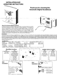
The 1978 Electronic Experimenter1s Handbook shows another version
of th& original C(~MAC ELF. It uses a simpler and more economical
data display than the original ELF, that specified expensive
Hewlett-Packard integrated hex-display chips.
As no advertisement could be found for the dual National hexdisplay specified, the circuit was adapted to the Monsanto dual
hex-display, their MAN6640, a common cathode device. This has 2
orange, 0.56" high digi t s , The c tr cut t produces the hex numerals
and alphas, with Ib l and 'd' being in lower case. The original 8
data LED's should, of course, be removed.
The four Ie's and the one dual hex-display are obtainable from
James Electronics, California, for Just over $10. This gives a
one-digit price of about $5, which compares favourably with the
H-P price of about $15 - $20 per digit (when obtainable). The
circuit is easy to breadboard, it can also be used to replace the
address LED's, if desired.
J3
«41
_ ..:0-
r!•
07 D6 OS 0+ ~
4050
7
..; 1\ 7
~
~ '7
7
'J
a
I
1-
U
7
, "1I
~
I
+Sv
~
3
03 D2 DI
DI
~ r-:7.,..' --:oj/......:3T-~9.... 40S0
I
1.&"
12.
,
,
7
liS
.2
7. ,\"1
l
¥
''''
,
7
~---+-:'H
.9368
h+--Tl
I"
"
~l:!~~:::r~,,,-::1~~..r.~':r.:::'1"""
~1
~!2 ..... -!t:,
-IZ"OA-
ab c d eJ9/-/
'-I
I I I f
(9)
"::j::-:::!~:::"":'~F'""",r.~:r-~::l""""
:::~CD"''''~'''
abcdeJ9
MAPl6640
A MONITqR FOR ASCII KEyBOARD AND DISpLAY
Tom Crawford
In thi s art icl e I shall descr ibe a IIOnitor program I am In the
final stages of debugging.
First, though, I would like to
elaborate on the reasons for having a monitor.
The first contact most people have With their own micro-computer
is through a hex keypad and a row of LEDs~ This means of I/O works
OK as an introduction to the machine, but soon becomes tedious for
those who attempt any serious programming. Another irritating
factor is the loss of memory contents each time the power is
switched off, resulting in the need to reload all the code you are
working on, 1/2 byte at a time, through the keypad.
The solution to the 2nd problem for most people requires adding
a cassette interface to your microcomputer. This allows speedy
reloading of software each time you use your system.
The solution to the problem of easier input and output usually
takes the form of a serial ASCII terminal. This can take many
shapes, depending upon the size of your wallet. In my case, I have
constructed a TVT-2 video terminal (also known as a CT-I024 ) with
a 64 key keyboard, and a serial interface. The serial interface
adds some complexity to the hardware, but allows substitution of a
hard copy terminal such as a Teletype when my bUdget permits;
simply by changing connectors.
The ASCII terminal is a general purpose terminal~ in the sense
that it allows the entry of machine language data now, and can be
used for higher level languages employing the full ASCII character
set at a later date.
The problem at this point is to tie together the ASCII terminal,
the cassette interface, and the micro-computer into a system which
can stand alone for machine language use, and which will provide
the detailed I/O routines which service the terminal and the
cassette, for the use of the higher level language programs; This
is the purpose served by a monitor program.
Virtually every computer system has a monitor; and many of the
simpler ones provide similar features.
I chose a monitor I was
familiar With, The Motorola MIKBUG monitor, and re-wrote it for
an 1802 with my particular I/O arrangement.
The result has been
nick-named "RIKBUG".
THE RIKBUG MONITOR
I
RIKBUG,' as currently wri t t en , is 750 bytes long, and interfaces.
to a serial ASCII terminal via the a-line (output) and EFI
( input ). The routines assume a frame composed of I start bit, 7
data bits, I parity bit (even parity) and 1 stop bit.
RIKBl1G
initially determines the baud rate of the serial device by timing
the start bit of the first character entered. This feature has been
tested at 300 and 1200 baud, and works qUite well.
RIKBUG also handles a KC standard cassette interface as written
up in Issue #3 of IPSO FACTO.
a is the output, while EF2 is data
input and EF4 is clock input~ The routines perform a software UART
function, which will allow use of the cassette interface at 300,
600,
or 1200 baud (irrespective of the baud rate of the ASCII
terminal ).
'
( 10)
RIKBUG provides the following functions, each started by the
associated key letter'
G - Go to target program
L - Load from tape
M -Memory change
P - dump to tape
R - display contents of target stack
The monitor is highly subroutinized, and makes use of RCA's SCRT
routines (modified to save the D-register contents). Therefore any
user-generated software can make use of the terminal and tape
I/O routines simply by making a SCRT call, with data passed back
and forth in the D-register. (This assumes RIKBUG is co-resident
in memory with the user1s program, of course ! )
RIKBUG is not yet completely debugged, as I mentioned earlier.
The G, M, P and R routines all work satisfactorily. The L function
reqires mods to make use of the external clock on EF4, I am
confident it will be working shortly.
I am willing to make copies of RIKBUG available to anyone
seriously interested. I will supply an assembly language listing;
including extensive comments and the assembled machine code.
No
cassette tapes are available yet.
Please send a 9" X 12" SASE
(50 cents Canadian postage only please ) to'
TOM CRAWFORD,
50 BRENTWOOD DR., STONEY CREEK, ONT., CANADA L8G 2W8
( The listing is 28 pages long, so if you scrimp on the envelope
or the postage, you won't get it ).
This software was assembled using Wayne Bowdish~s 1802 crossassembler.
Some extended instructions (~+" instructions) are
used,' such as "+CALL" and "+RETRN". These aresel f-explanatory;
for the most part.
Further details can be obtained by contacting
Wayne. See his article in Issue 12 of IPSO FACTO.
LEITERS TO THE EPITOR
( Ed. Note. The following letters have been edited slightly to
conserve space. The Editor apologizes for any errors or omissions
which result. TC )
Dear Sirs.
I have heard of your club and newsletter in the last issue of
Popular Electronics.
I own an 1802 based ELF II and am very
interested in your efforts.
There is a local hobbyist computer club trying to get a start
here. I will relay any info to the clUb.
I have several projects under way currently and would be
interested in contributing articles to your letter. (please do.TC)
Thank you very much., Claud Hesselman~ 805 "0" St.
Chesapeake, Virginia, U.S.A. 23324
Dear Tom.
I read your announcement in the Nov. issue of Byte. I wish to
obtain more information on your 1802 Users l Group. I am in the
process of building a computer based clUb using an 1802 computer
we built from scratch.
As you can see any into regardlnq your
users l group would be appreciated.
Thank you, Mark Moore, 36 Waverley Dr., Guelph, Ontario, NIE 6C8
( J 1)
Sirsl
Reading Issue #3 of I PSO FACTO; a couple of thi ngs caught my
attention •••
Page 3. The diagram labeled "bus conversion" cannot be expected
to work properly. Since a 1404 has totem-pole outputs ( i.e.
active pullups ) it is probably capable of sourcing more current
in the high state than the average CMOS output is capable of
sinking. Combine this with the (unspecified) pullup resister; and
it is unlikely that the CMOS side of the bus will ever get low
enough to register a good zero. A 1405 open-collector equivalent
(or better the high-voltage 1416) should be used. Furthermore; the
logic used to determine bus direction could be either more complex
or more simple than that shown,' depending on where memory and I/o
devices reside.
If as implied in the accompanying text, only the
CPU is on the CMOS side, then bus direction could be defined
adequately by (~N3), which is high during memory fetch and INP
cycles, and low otherwise. If on the other hand you want to allow
arbitrary I/O and/or memory on either bus; then the Bus Direction
signal must be cognizant of the allocation of memory, and
must
know whether this memory access reters to CMOS- orITL-bus memory.
In interfacing my 1802 system to an S-loo expansion bUs, I chose a
middle ground l while I expect' both I/O and memory to be on either
the TTL or CM(~ side; I determined a priori where the CM(~ memory
is ( first 8K ) and that I will never access the .ITL bus for both
I/O and memory ( the S-loo spec disallows this anyway), so my Bus
Direction is driven by the high three address lines, Mlm, and the
N-lines.
I will send in a schematic when I am sure it runs.
(please do! TC)
,
With a little more cleverness it is possible to get all 32 (or
64 ) characters on the TVT-6 line. This is based on the fact that
the RTS instruction in the 6502 has a much closer cognate in the
1802 than SEP.
The RET instruction is a two-cycle instruction
which both does what the SEP does and can be coded to do it with
two consecutive memory accesses. Lacking the freedom to specify
the second byte (it must be the same as the opcode), this requires
that RO, not R14, be used as the main line PC, but this is an
inconvenience only to the extent that DMA is disallowed during TVT
operation (it would mess up the timing anyway).
One further
requirement is that X=P during the scan routine, but I do not see
that as a major difficulty. It might be simplified if P=7 (since
the RET instruction will always set X=7 on exit). If it is desired
to preserve 0 through the scan routine, the XRI instruction ( FB )
could be used instead of LOI (F8), an' even number of these
restores the 0 to its original state (since there are an odd
number in the scan routine, one more is reqUired in the main line).
Alternately, one OUT instruction could be sacrificed ( remember,
X-P tor the RET ), Which outputs a constant 6n on' the designated
port;
For all you guys who want a resident assembler; I have one in
the works.
It will generate relocatable code, so a relocating
loader is inclUded, at what I hope is a reasonable price. It
should be ready within a month or so.
Tom Pittman (Itty 8itty Computer Co.)~ P.O. Box 23189
San Jose, CA,
(USA) 95153
( 12)
Dear Tom l
I am replying to Wayne Bowdish's letter of November 30, 1917,
which I received last week ( the holiday mail again).
Thank you
for sending copies of the first three issues of your newslettert
I applaud your enterprising association.
Now of my project.
By now you should have read my plea to all
CDP 1802 users in the August issue of DOJ. The response has been
great but the project is still prenatal. A questionnaire was to
have been sent to all respondents and other interested parties
this week, but is being delayed pending the outcome of this
correspondence.
Two of our biggest problems in forming a "Chicago" club were time
and lack of capital to finance a newsletter. If there is anything
that we can do from this end, please let me know. Meanwhile please
find my application for membership in ACE along with a $5.00 check
enclosed.
What will eventually happen is for ACE to become the headquarters
for many 1802 Spartan clubs throughout the world.' A national
meeting is not too far fetched. There are many who are yearning
for a userJs club. Yet; I can appreciate Milan Skodny's comments
in the second issue of IPSO FACTO.
A good point to bring up at your next meeting is how large do you
want ACE to become? (Think in particular about finding someone to
run this large an enterprise. TC). I think regional clubs who
remain
autonomous while operating under your banner is an
excellent idea.
There are many who, like myself, have taken it upon themselves
to generate some interest in the COSMAC system, Ie. Ross, Wirth, Ed
McCormick, H.Shanko, and others. ACE needs representation as well
as exposure. Can we consolidate all of these efforts through ACE?
One more item, to Paul Birke of Burlington, Ontario,' tell him to
contactl Robert Jerald, 103 Coventry Drive, Lakewood, N.J.
08701
He should be finished interfacing the National Semiconductor
numbercruncher chip to his 1802 uC.
Yours very truly,
Phil ·Gennarelli (CDPJ802 National Clearinghouse)
Dear Sirt
Thank you for sending information. I would like very much to
Join your club. Inclosed is my fee.
I have an ELF-II, 1802 basedi system which I purchased as a kit
from Netronics (advertised in Popular Electronics). I am working
on a tape interface to an Alphatype Typesetting machine. It uses
reel to reel decks in a saturated digital switching mode and has
two channels (one used for a clock track).
Is there anyone out there who knows, of this type of recording?
( If so, please contact Barney directly. let me know how you make
out, Barney. TC)
I would also like to know where I could buy '86 pin connectors
for the ELF-II, also I need a RCA Data Book.
Thank you, Barney Widner, Alpha SerVice, 24 W Ethel
lombard, Il 60148
(13)
Dear Wayne,
Thanks very much for your letter of Oct. 19th. I was in Canada
during Sept. on home leave from a CIDA project that I am working
on in Kenya. I am here in a Canadian Govt. aid project and am
teaching and writing courses in Microwave technology for the Posts
and Telecommunications Dept. of the Kenyan Government. Expect to
be here approximately another year and then likely back to Canada
where I work for Canadian Pacific Telecommunications.
I attended the IEEE Conference in Toronto during my home leave in
Sept. and got "turned on'" by the micro-processor explosion that
s~ems to be taking place.
I purchased a basic set from Mr. E.
Tekatch of Tektron Equip. Which is still not to hand but expected
shortly.
My background is not entirely lacking in digital
techniques but I was most pleased to get your letter as I
certainly have lots to learn in the new field of microprocessors.
In other words, I am a real beginner and very keen to know more
about the construction and uses of this obviously very versatile
device. I don't know what I can contribute at this time but would
be most happy to have your newsletter and any other information on
developments of the RCA 1802; My application and cheque for $5.00
are herewith enclosed.
I am particularly interested in ASCII or BAUDOT interfaces as my
connection with CPT could give me access to retired teletypes that
could be available at very reasonable cost. Maybe I could help out
the club by putting in touch with sources of this sort.
(Definitely! Te)
In the meantime, thanks again and keep the info coming.
Sincerely~'
Eric Duggan, Box
30305,~
Nairobi, Kenya, East Africa
Hi,
Just a qUick note to let you know I enjoyed the two back issues
of the newsletter. they have been very helpful.
I recently built a ELF II 1802 processor, but have not expanded
the unit yet. I am an amateur radio operator and build all of my
equipment, so I will probably be building some hardware for the
ELF.
The editor program and the code program in the newsletter work
qUite well on the ELF.
Please start my newsletter with issue #3 so I don't miss any
articles.
Bob Hillard
Dear Tom,
I have formed a small computer club in the local Junior High
School I teach In. We have ordered and are waiting for a 'Super
ELF' from Quest Electronics In California - you have probably seen
it advertised.At any rate I was most interested to see your notice
in the latest BYTE with regard to 1802 users and your· plans for
memory expansion, I/O, moni tor programs and a Basic interpreter.
We would like to correspond With you if possible about these
developments. Could we be put on your maIling list if one exists?
I would be more than willing to defray any costs, etc. Hope to
hear from you soon.
(You will. Keep in touch. TC)
Yours trUly,
R. Herbison, RR 2 Horne Lake Road
Port Alberni, B.C., V9Y lL6
(14 )
MEMORY-MAPPED I/O
tor the J 802
Tom Crawford
In the world of micro-processors today, there are 2 main
techniques available for I/O to and from peripheral devices. One
technique uses special instructions and special hardware signals
for input and output. The 8080, Z80 and 1802 micro-processors make
this method available, although the implementation is somewhat
different in the 1802 as compared to the 8080.
The other technique requires that I/O devices be connected to
the CPU as though they were memory elements. The CPU reads from
or writes to the device in precisely the same manner as it reads
from or writes to memory.
The only difference between an I/O
device and a memory location is the address. All micro-processors
can use this techniquel the ones which must use it include the
6800 and 6502.
The 1802 employs 3 I/O lines ( NO, NI, N2 ) and the MRD line to
implement I/O. The INPx and OUTx instructions (x = I to 7 ) are
supplied to control this I/O technique. The hardware connections
for up to 3 input ports and 3 output ports are extremely simple t
one N-line is assigned to each port, with the state of MRD
distinguishing between inputs and outputs. Only the folloWing I/C)
instructions are us ed t INPI, INP2, INP4, OUTI, OUT2, OUT4. This is
the I/O implementation used on the TEK-1802 to handle the on-board
keyboard and data LED display under program control.
The addition of a simple 3 line to 8 line decoder to the N-lines
allows up to 7 input ports and 7 output ports, and uses the full
complement of INP and OUT instructions ( note that NONIN2=OOO
cannot be used for I/O)~
This implementation is illustrated in
Figure 98 on page 77 of the RCA 1802 USERS MANUAL ( MPM-20IA ).
I am presently planning for some I/O devices I intend to add to
my 1802.
These include UART's, relay outputs, logic I/Oi and
analog I/O.
I need more than 7 I/O ports. What do I do ?
The 1802 USERS MANUAL shows one possibility, known as 2-level
decoding of the N-lines ( pages 78 - 79, Figure 99). In my
opinion, this method is needlessly complicated, both in the
hardware and in the software reqUired to use it.
I intend to implement memory-mapped I/O on my 1802 system. It
prOVides more than enough I/O addressing, and uses the eXisting
memory addressing hardware and software to do this. The only
decision reqUired is which memory addresses will be used for
memory, and which for I/O. Since the total number of unique memory
addresses exc eeds 65,000 , there is pI enty of space available for
I/O devices, wi thout any .noticable sacrifice in memory space. Each
I/O device simply watches for its unique address on the address
lines, then either reads the . data lines, or writes to them,
depending on the state of MRD.
Admittedly, watching 16 address lines for an unique combination
requires extensive hardware for each I/O device, but this can be
simplified considerably if all I/O devices are located in the same
region of memory. Then the high order address lines, which are the
same for every I/O device, can be monitored by only 1 set of
hardware, which produces a single signal which indicates whether
any I/O device is being addr es sed , The same technique can be
applied to smaller blocks of devices within the I/O device space,'
as well.
( 15)
It is convenient to assign a full memory page for I/O addressing.
this allows up to 256 input and 256 output ports, and still leaves
65,279 words of memory.
If more I/O devices are required, simply
assign 2 pages to I/O devices instead of I. This allows up to 512
I/O ports.
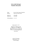
Figure # I shows the hardware required to watch for selection of
I/O page #FF by the CPU. The logic produces a signal called IOSEL,
which is true if the I/o page is selected. This signal is valid
anytime that TPA is false. In particular, it is required to be
valid while TPB is true.
If you add this signal to your buss
structure, then it can be used by any I/O board card you make, but
only the first card needs the hardware shown in figure #1.
Note
that this circuit is guaranteed to work at 5 volts with a CPU
clock frequency no greate~ than 5 MHz ( TPA > 200nS ):
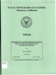
The circuitry shown in figure #2 is typical of that used to
decode individual device selection for several devices on I card.
It provides o-true strobe pulses, co-incident With TPB, for up to
4 input and 4 output devices. The 4 device addresses must be
adjacent, but may be selected anywhere in the I/O page with 6
Jumpers or a DIP-switch connected to the second input of each of
the XOR gates.
This selection circuitry is a careful mix of CMOS and TTL logic.
The CMOS gates are required to buffer the data from the buss.
Bseries CMOS is specified, in order to drive I TIL input from each
CMOS output. The TTL logic is required in order to do the
necessary decoding in a reasonable amount of time. The delay time
from TPB input to any strobe output is 172 nS max. (90 nS typical>.
Since data on the bus is valid for 1/2 clock cycle after the end
of TPB, then this decoding circuitry is useable With clock
frequencies up to 2~9 MHz gauranteed, and up to 5.5 MHz typical.
( TTL driven from CMOS B-series is based on experience. For those
desiring best noise margins, substitute a 74LS42 for the 7442 IC.>
A similar circuit to provide decoding for 8 inputs and 8 outputs
can be made by using a 74154 instead of a 1442.
This is shown in
Figure #3.
In summary, I have shown a method of mapping I/O ports into
addresses, as an alternate to 2-level N-line decoding. I feel
that; for more than 1 I/() ports, memory mapping can be implemented
with less hardware,' and can be used With simpler software, than 2level N-line decoding.
References
I>
2)
3>
USER MANUAL FOR THE CDPI802 COSMAC MICROPROCESSOR,'
RCA HMPM-20IA; pgs 13-19
"Ciarc1a's Circuit Cellarl Memory Mapped I/OM,
BYTE magazine, November 1911, pgs 10-16
"Build a Universal I/O board", W.T. Walters,
KILOBAUD magaz1 ne, Oc tober 1971, pgs 102-108
( 16)
+sv
I
TPA
t"f
..
~
L.
f!+
/6
MPC
S-
4-
/VI fJ. 1
{(
Me
s
j-1A 3
10
r: P 4f~IP ~
j:..
Me
7
11+5 os
3 Itt-50 1
1/
/r-
111
f7
5
/B
1<1
6
2C
at
7
,3
h2.
It
~
7
MA~
1=
f
1
to
U-
b
b
14-
lCSE!-
15
8
(r/.o
Ph=£
= FF)
d
-I
I I I I I
1EI.QURE
M RO
M~O
•
I
f\1A 1
T5V
T
/6
MA2
I
7'+4;e
Z
C~'T
"c
(p)
3
IA
~I
Cl. T ,: I
1+ (8)
'+
5
(:
O(JTf=e
7
IN '':3
q
ooT '.;"3
I~
M (13
~
j"
,...1 A 'f
~
•
MA5
eb:
o;o.nB
I
if.()308 :
MA7
«J
I? (p)
C~
TPB
13
J.
Mf/6
IOSE.L
I
S
4-.
...
CD,
I
'hHas ----
FIGURE
'2
<17 )
IN '':2
10
/1/. c .
/I
N.C.
+~v
Ct'
'J
O! C
er
. -,
....
IN /. a
DUT ,"/ 0
N:lO
-
+5V
-
...
-
-
OU-::: I
~
f\1
A0
/8 (17 I)
----+-+---'f----~
,/
'/·03': F. ;
-----t---+----~\'\.
,..1 A 7 .-----t------~lh
CD ".03 (Ie I
IO 5 [L
TP8
J..
."
-
.•~
-
----------'-I'>-~
c a «osce ;. _ .. _:
oj.
"2
0iJ, tI]
~
III
I
EIGlteE
I.J
( 18)
it-
'1-
;
5
If
IN
13
cJ o t:
-~
1f t
IN
t-'6
15
:JI/
16
IN
/7
/2.
1-
co :
-:: u' T
-----t--i--+--+---'--\h
CD
•2
/ ,,,! "3
-'1
5
110.,1
J •
-j
N ,t.J 3 -----+"--i--+--+--+--\"
fVl.~
I
~
7~/5lf,-
"'j ,,\ '1'
'=
I '\
fv(/4 I
r
5
;;6
"7
O"T~7
+l.- I, VULTS ON THE IEKATCH BUS
Tom Crawford
I recently added a Kansas City cassette interface to my
micro-processor system. My system is based on the TEC-1802, which
employs a44 pin buss structure. This buss has provisions to supply only +5V power. Also, there are no spare pins on the buss. My
KC interface requires +/- 7.5V to supply 2 op amps. In addition,
I intend to add a number of other circuits requiring a +ve and -ve
supply, such as A-D converters and 3-supply UARTs (cheaper than 5V
only UARTs!). I decided that +12V and -12V would serve my purposes
and that these should be available on the buss.
Careful examination of the existing pin assignments showed
several which are provided for operation of an 18~2 I/O Port IC on
the CPU board. Since 1 do not have an 1852 chip, these pins are
unused in my system. 1 therefore made the folloWing changes'
pIN'
OLD USE
NEW USE
2
CS I, ~
-1 2V DC
24
SR
+12V DC
25
CLK(1852)
CLK(1802)
You will note also the change in the assignment of pin 25.
This one requires some cutting of traces and a Jumper, to connect
the 1802 chip to the edge connector on the CPU board. Now you can
build an oscillator on another card, and plug it into the buss
structure. As a bonus, the CPU clock frequency is available for
other purposes, such as Real Time Clock interrupts, a UART timebase, synchronous logic, etc~
I would recommend that you cut the traces on the CPU board
which connect edge connector pins 2 and 24 to the I/O Port socket
(25 was cut in the previous paragraph), Just to avoid potential
problems at a later time~
.
Although I haven1t made a pin assignment yet, I have been
looking tor a pin to hang an InSEL signal on, tor Memory-Mapped
I/O. Some thoughts on this subJect include' one of CE2 (pin 43) or
CE1(pin 21) can be freed up, leaving only 1 line to select the 256
bytes of memory on the CPU board. A little extra logic will be
required on the ;75K memory board, to drive the remaining line. Or
one could remove the 256 bytes entirely from the CPU board, freeing up 2 lines of the buss. The 2 memory chips can be piggy-backed
on 2 chips of the .75K memory board, making it a IK memory board.
It is also possible to free up some unused N-lines or Ef lines.
I would be interested in feedback on my +/-12V pin aSSignments, and on the other comments I have made regarding the Tekatch
buss. I emphasize that these are not standard changes,
but only
modifications to my personal system at this time.
( 1y)
MEMORY TEST ROUTINE FOR THE IFC-18Q2
A. Dunlop
A recent algorithm by Knaizuk and Hartmann (IEEE Transactions on Computers. April 1977) outlines an ultra-fast RAM test.
This algorithm is employed in the test routine shown in Listing 1.
The memory test routine will detect any stuck-at-I or
stuck-at-O fault in a RAM. including the memory itself. the
address and data lines. and the address decoders.
It sacrifices
testing efficiency to a small degree so as to achieve simplicity.
run time is short compared to some other test routines.
Operation of the routine is described in three steps processed for three phases with complemented data used in alternate
passes. Each phase is made up ot the follOWing thrp.e steps'
I. A Data ~yte is stored in every location to be tested
2. The complement of the Data Byte is stored in every third
location
3~ Memory is checked for all locations in the test region
It is important to note that the above three steps must be done as
three seperate iterations.
The three steps are performed three times. once for each
phase. with the position of the complemented Data Byte changing
each time. Then the Data Byte is complemented and the next pass is
begun.
The Data Byte is initially #FF giving an FF FE 00 FF FF 00
FF. •• pa ttern for the t i rst phase and FF 00 FF fF 00 .FF FF • .-. tor
the second phase and 00 FF fF UO FF FF 00.;. tor the third phase
of the first pass. The second pass first phase generates a 00 00
FF 00 00 FF••• pattern.
Memory is tested as a group of bytes between. and including. any two arbitrary addresses allOWing small sections of memory
to be tested. The low address value of the area to be tested is
placed in bytes 2 and 3 of the program at the label 'BEGIN' and
the high address limit is placed in bytes 4 and 5 at the label
~END'. Testing progresses from high to low address so as
to simplify the limit-checking.
The program starts at byte 0 with a
branch around the data area to the initialization section.
After 256 complete passes the program will halt unconditionally. The user may wish to NOP the halt instruction to let the
test run continuously.
If a fault is detected; the program will halt conditionally with the most significant byte of the fault address displayed
in the Data leds. and the Q led indicating what was expecJed to be
in the memory byte at the fault address' Q reset when #00 was expected and a set when #FF was expected. PreSSing and holding the
'llkey Will permit the least significant byte of the fault address
to be displayed. Upon releasing the ' I' key the program will continue.
The test routine can be executed in any page of memory
since it references the absolute page address at initialization
time.
This test routine will not solve memory problems or indicate the cause directly. It serves only to direct. the user's attention to specitic problem areas if they exist;
(2U)
-
llEMOAY TEST AOUTINE -
I
2
3
4
5
6
7
8
9
10
....
02-FE!.'-7e
17.451
.TITlE -- IIIEIlORY TEST RIlIITINE ,IlElloRY TEST RCA 1802 JAN. 1978 AD
'REGISTER ASSIGllENT
,RO
P COUNTER
,RI
PRESENT BYTE ADDRESS IN IIEIORY
'R2.1 PHASE INDEX (3 PHASES To TEST)
'R2.0 INDEX REFLECTING PHASE INDEX
ADDRESS OF llEMORY CoNTAINING BEGIN
'R3
ADDRESS OF llEIiORY CIlIf'TAINIIfO END
'R4
ADDRESS OF TEMPIlRARY BYTE
'R5
IfUMBER OF COMPLETE PASSES
'R6
'R7.0 DATA BYTE
II
12
13
14
15
16 0000 30 07
17 0002 FF FF
18 0004 FF FF
19 0006 00
20 0007 90
21 0008 B3
22 0009 B4
23 OOOA B5
24 OOOB F8 02
25 OOOD A3
26 OOOE FB 04
27 0010 A4.
28 0011 F8 06
29 0013 A5
30 0014 F8 00
31 0016 B6
32 0017 A6
33 0018 A7
34 0019 F8 02
35 OOIB B2
36 OOIC 7A
37 0010 A2
38 OOIE
39 OOIF BI
40 0020 04
41 0021 AI
42 0022 24
4J 0023 39 2C
44 0025 82
45 0026 32 2C
46 0028 22
47 0029 21
48 002A 30 25
49 002C 13
50 002D 81
51 002E E3
52 oo2F F7
53 0030 23
54 0031 91
llElITST.RCA
RCI802-VOI
,
START'
BEGIN'
END'
TEllP'
INZ'
POOO.
POlO'
P020'
POlO'
P040'
BR
.DBYTE
.DBYTE
• BYTE
GHI
PHI
PHI
PHI
lDI
Plo
lDI
Plo
lDI
Plo
lDI
PHI
Plo
Plo
lDI
PHI
AEO
Plo
lOA
PHI
lr»f
Plo
DEC
BNO
GW
B2
DEC
DEC
SR
INC
Glo
SEX
Sll
DEC
GHI
,**
, CAUTIIIN .**
INZ
,FFFF
'FFFF
0
RO
R3
R4
R5
BEOIIf
R3
END
R4
TEllP
R5
0
A6
R6
R7
2
R2
R2
A4
RI
A4
AI
R4
P040
R2
P040
A2
RI
P030
R3
AI
R3
R3
RI
,
RANGE FoR "'BEGIN"'
I - 'FFFF
'BEGINtfING ADDRESS TO BE TESTED
'ENDING AOORESS TO BE TESTED
ITEIlPIIRARY lllCATI (If FIIR OllTPUT
'INITIALIZE HIGH REO TO
THIS PAGE ADDRESS
,,
,,
'R3 SET TO ADDRESS CF BEGIN
..,R4
, SET TO ADDRESS Of END
,R5 SET TO ADDRESS CF TEMP
,,
'R6 SET TO '0000
'DATA BYTE INITIALIZED AS '00
,SET PHASE INDEX FOR 3 PHASES
,
'RESET 0 FOR STEP I - EVERY BYTE
'R2.0 SET FoR -FUNNY SUBTRACT-
,'AI PRESENT TEST BYTE START AT END
,,'RESET A4 To poiNT TO END AGAIN
'STEP I BYPASS
,SPECIAL ACTION FOR STEP 2
'SUBTRACTION COMPLETE
,
,,-FUNNY SUNTRACT- '''-RI-A2.0
'TO GET LEAST SIGNIFICANT BYTE
,,SET
of "'BEGIN"'
"'BEGIN"'
,,TO GETX FOAllOSTSUBTRACT
SIGNIFICANT BYTE
,
of "'BEGIN"'
MEMORY TEST RIIUTINE I
2
3
4
5
6
7
8
9
10
1\
12
13
14
15
16
17
18
19
20
21
22
23
24
25
26
27
2B
29
30
31
32
33
34
35
36
37
38
39
40
41
42
43
44
45
46
47
48
49
50
51
52
53
54
0032
0033
00,)';
0036
0038
003A
003B
OOJe
0030
OOJE
003F
0040
0041
0043
0045
0046
0047
0049
004A
004B
004C
0040
oo4E
004F
0050
0051
0052·
0053
0054
0055
0056
0057
0059
005A
OOSC
0050
oo5F
0061
0063
0064
0065
0066
0067
0068
0069
006A
006B
0060
006E
006F
0070
0071
0072
0074
77
3B 43
87
FB FF
39 3F
87
51
21
21
38
51
21
30 2C
31 49
7B
92
30 ID
44
BI
04
AI
24
92
A2
13
81
E3.
F7
23
91
POSO'
P06O'
PIOO'
PliO.
n
3B 7E
82
32 61
87
FB FF
30 65
F8 03
A2
87
CE
7B
38
7A
EI
F3
32 7A
E5
91
55
64
25
3F 72
81
PI20'
RC1802-YOI
5MB
Bll
Glo
XRI
BNa
GlO
STR
DEC
DEC
SKP
SIR
DEC
BR
BO
SEa
GHI
BR
lOA
PHI
lr»f
Plo
DEC
GHI
Plo
INC
GlO
SEX
Sll
DEC
GHI
SIiB
Bll
Glo
BZ
Olo
XRI
SA
Lnl
PlO
GLO
PI301
lSZ
SEO
SICP
AEO
SEX
XIIR
BZ
SEX
GHI
SIR
(JUT
DEC
BN4
OLO
P060
R7
'FF
POSO
R7
RI
Rl
Rl
RI
RI
P040
PIOO
R2
P020
A4
AI
R4
RI
R4
R2
R2
A3
AI
R3
R3
RI
P200
R2
PI20
R7
'FF
PI30
3
R2
A7
RI
PI40
A5
AI
A5
4
R5
•AI
llEllTST.RCA
02-FEB-78 17.451
-
BEGIN
'PRESENT ADDRESS
IDONE THIS STEP "HEN DF-o
'GET DATA BYTE
,CoMPlEllENT IT
'STEP I BYPASS
, SPEC IAl ACTlIIN FoR STEP 2
,SToRE DATA BYTE
'DECREllENT PRESENT ADDRESS T~ICE To
'BYPASS NEXT T"o BYTE ADDRESSES
,
,SToRE CI*PlEllENTED DATA BYTE
,'DECREllENT PRESENT ADDAESS
,FIIfISHED STEP 2
,SET 0 FOR STEP 2 - EVERY THI flO BYTE
,GET PHASE INDEX
,GO Til STEP 2 ENTRY
'STEP 3 TEST FoA CORAECT DATA
,,
'RI SET To END ADDRESS
'RESET R4 To polin To END AGAIN
'GET PHASE INDEX
'SET FoR INDEX TO EVERY THI RD BYTE
FIIR THIS PHASE
,
'. X FoR SUBTRACT "'BEGIN"'
,,SET
,,
'PRESENT ADDRESS - BEGIN
,'DllNE STEP 3 "HEIf OF-a
TO TEST·THIRD BYTE
,'BRANCH
,CI*PlEllENT DATA BYTE
,,
,,'RESET R2.0 TO TEST THIRDFAOllBYTEHEAE
,,SET 0 IF I)elFF
'RESET 0 IF 0-'00
'SET X FoA EXCLUSIVE OA
,CollPARE NITH llEllOAY BYTE
'OK
'SET X FOR oUTPUT FAULT AOORESS
,,
BYTE OF
,,oUTPUT aosr SIGNIFICANT
FAULT AOORE.'iS
,'NAIT FOA PUSHED
"'I"'
-
RC1802-VOI
MEMORY I'EST RnUTINE -
I 0075
2 0076
3 0077
4 0078
5 007A
6 oo7B
7 OO7C
8 oo7E
9 OO7F
10 0080
II 0081
12 0083
13 0084
14 0085
IS 0087
16 0088
17 oo8A
18 oo8C
19 0080
20
STR
(JUT
DEC
B4
DEC
DEC
8R
OHI
PLO
DEC
BNZ
INC
GHI
BNZ
OLo
XRI
BR
OLO
BR
.EHD
55
64
25
37 78
22
21
30 50
92
A2
22
3A ec
16
96
3A 85
87 .
FB FF
30 18
82
30 IB
P140'
P2OO'
P210'
0002
oo3F
OO8C
END
P060
SrART
0004
0043
0000
INZ
Ploo
TEMP
PROGRAM SIZE - ooBF
o ERRORS DETECTED
•
02-FEB-78
PAOE
17'45'53
3
,
BYTE OF
,HlUTPUT LEAST SIONIFICANT
FAULT ADDRESS
R5
4
R5
•RIR2
PliO
R2
R2
R2
P210
R6
R6
'WAIT FOR I I I RELEASED
'R2.0-R2.o-l
,RI-RI-I
,
,,
'DECREMENT PHASE INDEX
'PHASE r"'DEX NoT -I, DO NEXT PHASE
'INCREMENT COUNT OF PASSES
,
.
AFTER COMPLETINO 256 PASSES
•IFF
,'STOP
R7
'COMPLEMENT DATA BYTE FOR NEXT PASS
POOO
R2
POlO
'00 DO ANOTHER PASS
'OET DECREMENTED PHASE INDEX
'On DO NEXT PHASE
,
RCle02-VOI
MEMORY TEST ROUTINE USER SYMBOL TABLE
BEOIN
P050
P210
MEMTST.RCA
0007
0049
0006
POOO
,PliO
02-FEB-78 17'45'53
MEMTST.RCA
oole
0050
POlO
PI20
oolB
0061
P020
PI30
0010
0065
P030
PI40
PAGE
0025
oo7A
4
P040
P200
002C
007E
OTHEij cum NEWSLE1TER,S
The following list shows the pUblications produced by other
clubs, which we have obtained, otten in exchange tor fPSO FACTo.
To see any ot these, simply contact any member of the ACE Executive at the next ACE meeting.
COSMAC ELF NEWSLETfER (Charles Manry, 2012 Williamsburg ce; S;,
Leaque City, Texas 17573)
- November 77 (3 pages)
- Decem-ber77 (3 pages) - includes a reprint trom IPSO FACTO
- January 78 (3 pages)
MCMASTER
UNIVEW~lTY COMPUTEI-l CLUI::$ (Hamilton, Ontario)
- Introductory Information. ~eptember II (I pages)
Tl-llANGLE AMATEUR
- August
- Sept.
(This
COMPUTEI-l CLUB (Po BOX 17~23, Raleigh, N.C. 27609)
77 (~ pages)
77 (2 pages)
club seems to have disappeared. TC)
TULSA COMPUTEW SoCI ETY (J.JO ~OX 1 I 33, Tulsa, Okl ahoma
- September 77 (4 pages)
- October
77 (4 Pages)
HANQUM NUMBER GENeRATiON FOR THE 18Q2
74101)
B.J. Murphy
Many computer applications require the use of random numbers.
Computer games such as STAR-TREK, TIC-TAC-TOE use random number
routines to set up initial conditlons.
You may be asking yourself "How can a computer generate a truly
random number"'" The fact of the matter is that computers cannot
generate random numbers - the computer can be programmed however,
to generate a "pseudo-random" number.
Before you turn the page to read the next article, have a lOOK
at listing I. This 1802 routine will generate random numbers from
o to 255. The program however, always generates the same sequence
of random numbers, thus we call this sequence "pseUdo-random".
By changing the initial. value of the variable "RANDOM"~
(statement 40) the program generates different sequences ot random
numbers. This initial value is formally known as the random number
seed.
An interesting technique is the use of the summation of powers
or two to achieve multiplication.
The equation in statement 9 of
the program can be changed to allow the mUltiplication of any
number.
If you wish to learn more about random number generation,'
consult the reference or any good Computer Science textbook.
REFERENCE'
Gri eser "PseUdorandom Number Generator", Byt e Magaz ine,
November 1977, page 218.
(23)
r
LOCN OBJ CODE
0000
0000
0000
0000
0000
0000
0000
0000
0000
0000
0000
0000
0000
0000
0000
0002
0003
0003
0004
0005
0006
0007
0008
0009
OOOA
OOOB
OOOC
OOOD
OOOF
0010
0010
0010
0010
0011
0012
0013
0014
0016
0018
0018
0019
0019
SOURCE STATEMENT
STMT
1
••••••••••••••••••••••••••••••• *••••••••••••••••• ••••••••••
•••
•••
2
3 •••
4
5
•••
•••
~
PSEUDO-RANDOM NUMBER GENERATOR FOR RCA1802
METHOD:
6
•••
7
8
1802 VER 1.2
•••
•
TAKE PREVIOUS RANDOM NUMBER,MULTIPLY BY 13
AND ADD 1
9 ••• MULTIPLY BY 13 BY USING:
13'N = N'2"3
+
N'2"2
+
•••
•••
N •••
10
•••
12
•••
•••
•••*••••,
••••, •••••• ,••••• "" •••••••••••••••••••••, ••,•••••
f ••
1 1 ••• REGISTER USAGE: RO=P.C.; R2=X REG; R3,R4=WORK
13
•
14
15 MAINLOOP LDI
PLO
16
CLEAR
17 •
SEX
E2
18
FO
LDX
19
SHL
20
FE
21
FE
SHL
A3
22
PLO
F4
ADD
23
24
52
STR
83
GLO
25
FE
26
SHL
F4
ADD
27
28
FC 01
ADI
STR
52
29
30 •
END OF
31
•
32 f
64
OUT4
33
B4
PHI
34
24
35 BUZZ
DEC
94
36
GHI
3A 12
BNZ
37
30 00
BR
38
39 •
39
40 RANDOM
DC
41 •
42
END
o DIAGNOSTICS GENERATED
3 SYMBOLS
SYMBOL TABLE:
MAINLOOP
0000
BUZZ
0012
RANDOM
0018
READY
F8 18
A2
•••~.
••
•••
•••
•••
RANDOM
GET ADDR OF PRfJIOUS RANDOM #
R2
SAVE INTO R2
R2 HIGH FOR SYSTEMS OVER 256 BYTES
R2
I-1AKE R2 X REG
GET PREVIOUS RANDOM #
R2
X2
X2 AGAIN
R3
SAVE N'2"2
D= N + N'2*'2
R2
STORE THE RESULT
GET N'2"2
R3
X2 AGAIN GIVES N'2"3
D= N + N'2"2 + N'2"3
1
FINISH BY ADDING 1
R2
STORE RESULT
RANDOM NUMBER CODE GENERATION
R4
R4
R4
BUZZ
MAINLOOP
DISPLAY RANDOM #
USE AS INTERVAL
DECREMENT
GET THE VALUE
DONE ?
YES .. ANOTHER RANDOM #
57
RANDOM NUMBER SEED
(24)
ROM
our
OF RAM
M. Pupeza
For those with the TEC 1802 3/4K Memory Expansion board, there
is an easy way to write-protect the (;MO~ memory page, making it
look for all intents and purposes like ROM. All that is requlred
is a SWitch, 2 resistors, an option81 LED indicator,' and some
wiring to eXisting spare gates in IC3 and IC4. The wiring is shown
in Figure 1 below. Be sure to cut the eXisting traces which
connect pin 20 of rC7 and rC8 to the"'MW1< line, when you connect up
the memory protect circuit.
With the switch in the "Normal" pOSition, 'the CMOS memory
operates as RAM.
In the "Protect" position, the memory cannot be
written into at all, hence looks like ROM.
As described in the
Expansion board notes, 2 "AA"-size batteries will maintain the
contents of your "ROM" when you turn off the power to the rest of
the system.
( Ed. Note l If yo~ do write to this block of memory when it is
Write-Protected~ both the CPU and the memory drive the Uata buss.
This could cause trOUble. TC )
Ie7
r-o-~ fiN ~O
rei
Ie,,"
MWR
7
--7'------1
$
12.
+5V
IC If
33K
1/
NORM.
i----~
c.e.»:
~T.
TO f,IvJP£ J.::
£ x 1ST I 1\' :;. L E /) S
fIGURE
ITEMS FOR SALE
COSMAC ELF (as seen in P.E. A'ugust 76> With
- built in 5v supply, 31 pin dual I/O connector.
- enclosed in box (RS *270-232>
- Hex keyboard controller for hex input and remote
control functions (no software needed>
- speaker With transistor amp.
- asking 575. Contact Richard Kindig~
712 Mitchell Rd., Clearfield, PA, 16830
Phonel (814) 765-4873
CAPACITORS, silver mica, for sale. All values (1-3000pf),
s.~u
each.
Call Gett Waite, (416) 385-5491,
or write 150 Mohawk Rd. E. Apt *611, Hamilton~
Ont., L9A 2HJ.
<25>
A~1.DItJEI1
Richard Kindig
KEYBOARQ APPRQACH
Here's some information on my HEX keyboard' the unit plugs
directly into my ELF with no modirications except tne addition of
a switch to disconnec~ the original input sWitCh. My ELF has 3
position input sWitches, having a center (none) position. nithout
this~
the switches would either have to be ORea with ~he Keyboard
( all switches orr) or removea rrom service Wi~h some sor~ of a
bus seperator.
Encoding 16 keys to hexadecimal can be done several ways. The
ways 1 've used Include t hp use of a HDO-165 encoder chip, and a
circuit discussed in a Popular Electronics article ( How to Fully
Debounce Low Cost Keyboards, January 1977, page 51).
Using the
..........~~,...............H ...........
-
-
-
-
-
-
-
-
-
-
-
.,...,...,..--+v.c
-
-1--oM
---------I==3~~~
---s~
----------i~r
..
-U'-
I
MJlJ
1lJV1
L
_
K[Y
'1--------Fig. 2. Wa11efoTms lIhow how
bouncing kell can produce
a clean lingle output.
Fig. 1. The circuit produces a 1-2-4-8 binarv code
and pro11ides a de bounced data-readv atrobe.
PARTS LIST
C 1-O.033-1&f'. 1'-V capac' tor
ICI·IC4-CD4068 8-input! NAND gale (for
Tn.. use 7430)
.
IC'~D4049 invening hex buller (for TTL.
use 74(4)
ICb--CD407' triple 3-input OR glle (rOt
rn, use 7432)
QI-2N6028 programmable unijunclion transiSlor
RI,Rl-08.00Q..0hm.
~.wan resistor
R2-1'.OOQ-ohm. V..wan resistor
R4.RI9--39.00Q..0hm. ~·wall resistor
R20-IOQ-ohrn. v..wan resillOt (TIl. only)
51-516-Nonn.aIly open.wilChlkeyboard
(26)
encoder chip is very easy since it provides internal pUlldown
resistors, debouncing and a key-pressed signal. The device however
is somewhat expensive, and has a dissipation of 88 millamperes.
(presently my ELF with hex displays and keyboard uses slightly
more than 200 rna. ). The P.E. circuit which I~m now using, has
C-MOS chips and a unijunction transistor ( for debouncing' l . ( s~e
figures 1 and 2 ).
With the encoded output, it is then necessary to latch a high
and low order digit sucessivily tor each key pressed. To do this,
L routed the Key-pressed signal to a flip-flop ror binary division.
(see figure 3 below) The Q and a outputs are then connected to
halt-monostable circuits, to produce a pUlse that would latch an
input before the key is released. These pulses are strobed to the
store pins of 4042 latches, and the output is then heidon the Q
output lines (which are connected to the center position of the
input switches).
The a output of the flip-flop is also buffered
and connected to an LED, which indicates whether the high or low
digit will be entered next.
'
An input switch and LOAD, MEMORY-PROTECT, and RUN switches were
mounted on the same board, resulting in a remote, hand-held
controller, connected to the ELF by a 16 conductor ribbon cable.
When using the keyboard, care must be taken that none of the ELF's
switches are out of their neutral position~
,
0,
I"
\.\ I
,..,
...
~
'
"
}IGOK
,t
~
5
'-
D
Q
aI
-1;
T 3.3k
VA
<::.
+S~'
tr'ilt.;-,
L
4-013
R
~
.
D3
I
Po!
\
sro«:
,
~
:~h3J~
~;;
e
~> 1'iJ~K
_:- '11if.
!:
i
I
r:
I
D,
J
. DJ.'
I
\.)/, , . -
.,.~v
--[>0 ®--=:~
+5V
L..-
G~
)'r-
'+-O if 2
Pol
STOPt:
LED
FIGURE 3
(27)
G:!
-
OUt
" -
D:r
,--
/fGlt'l
G. ' " - -
I
404Q
Q
C
I -c...
02.
It-.] '-;- 2
I
+5V
-
,)" J
,. -
I
DC
a" I--- D/
1'\.
.;
i
I--
D5
06
D7
INIERUPI PROCESSING ON IHE' 1802
Bernie Murphy
This article deals with a flaw in the interupt architecture of
the RCA 1802. If the reader does not understand the concept of
interupts, he/she should consult the references. The BYTE article
is highly recommended.
Having mastered all the basic 1802 instructions, I thought that
the interupt oriented instructions should be tested. I was shOCked
when 1 discovered that the 1802 does not have an 1nterupt disable
instruct f on.I lJage 65 of the RCA 1802 U~Eij MANUAL (I~PM-20 1m) states
"The RETURN and Ul~ABLE instructions can be used to set or reset
IE ••• A convenient method is to set X equal to the current P
value and then perform the REruRN (70) or OISABLE (71) instruction
using the d~sired X,P for the immediate byte."
For example' assume X=2, P=3
•
•
•
SEX
OIS
#23
E3
71
23
R3
set X=3
return to X=2, P=3, IE=O
immediate byte
•
•
•
The RCA manual forgets to mention that if an interupt occurs
Just after the SEX R3 instruction, the machine code preceeding the
DIS instruction becomes the data stac~ for the interupt routine,
not a very desirable Situation.
A possible solution to this problem is to add some extra hardware to the interupt system and use a latched output SUch as the a
line to control Irrt er up t s , ( see figure 1 )
+ 5Y - - - - - - - - l
R~a"EST
sea
--~
SCI
FIGURE
(28)
The sequence to provide flcritical processing" would bel
REQ
disable interupt gate
•
•
•
do critical instruction sequence
~EQ
It anyone has a software solution tor the above mentioned
problem please contact the editor ( or write an article !).
A simple program that demonstrates interupt processing is found
in listing 1.
Try it - short the interupt line to ground and see
what happens •••
If one desires to "fake an interupt" via software, the following
code will do the trickl
DEC
MARK
R2
~EX
R2
I Nt:
1Nt:
R2
SJ::P
R2
R1
decrement stack
get X,P into T register
reset X register again
Increment stack ( because ot MARK )
increment stack
fake interupt now~;.
The above method is very useful when debugging interupt
routines. Just think, the Motorola 6800 does all of the above with
one instruction, SWI ( Software Interupt ) !
REFERENCE~
I. "A LITTI..E BIT ON INTERUPTS", Byte,' December 1977, p.188
2. USER MANUAL FOR THE CDPI802 COSMAC MICROPROCESSOR,
MPM201A, RCA CORPORATION
3. COSMAC Microprocessor Product GUide, MPG-180, RCA
Corporation, p.6
4: IBM 360 Programming and Computing by Golden and Leichus,
Prentice-Hall Inc.
ERRAlTA
There are 3 errors in the Tape Test Routine found on page 30 ot
Issue #3 of IPSO FACTOI
ac
llL.O I NSrR...
NEW INSTR.
JA
7A
7B
3D
7B
7A
35
28
46
REQ
SEQ
BN2
(29)
SEQ
REQ
B2
~(jUHCt::
(
,
C
(J
(;
(
(:
(
(:
(~
(
(
l
(
'C
l
l
>'1
j
• .,
..JI
0000
0000
0000
0000
0000
0000
0000
0000
0000 F8 00
0002 Bl
0003 B2
0004 B3
0005 E2
0006 F8 24
0008 .11.1
0009 F8 FF
OCOB .11.2
OOOC F8 10
OOOE .11.3
OOOF D3
0010 F8 07
0012 .11.7
0013 611
0014 22
0015
0015
0015 Fa 04
0017 B8
0018 28
0019 98
001.11. 3.11. 18
001C 87
001D 7E
001E A.7
001F 52
0020 30 13
0022
0022
0022
0022
0022 42
0023 70
00211 22
0025 78
0026 22
0027 52
0028 7B
0029 F8 10
002B SF
002C 2F
002D 9F
002E 3.11. 2C
0030 7.11.
0031 30 22
0033
OOFF
OOFF
OOFF
o DIAGNOSTICS
7 SYMBOLS
SYMBOL TABLE:
MAINTASK
0010
MA INLOOP
0013
MAIN!
idJ2 VEH 1.
~'l'A'l'I::MI::NT
1 *******************************1******************
2
3
4
5
6
*** 1802 DEMO PGM SHOWING INTERUPT PROCESSING
***
***
Rl
INTERUPT P.C.
* **
R2
STACK (X REG)
***
***
**,
**.
***
R3
MAIN TASK P.C.
***
7 ***
***
8 **************************************************
9
10
11
12
13
111
15
16
17
18
19
20
21
22
23
24
25
26
27
28
29
30
31
32
33
34
35
36
37
38
39
40
41
1I2
4'-3
44
LDr
PHI
PHI
PH I
SEX
LDI
PLO
LDI
PLO
LDI
PLO
SEP
MAINTASK LDI
PLO
MAINLOOP OUT4
DEC
*
*
MAINDLY
LDI
PHI
DEC
GHI
BNZ
GLO
SHLC
PLO
STR
BR
a
Rl
R2
R3
R2
INTERUPT
Rl
STACK
R2
MAINTASK
R3
R3
7
R7
R2
4
R8
R8
R8
MAINDLY
R7
R7
R2
MAINLOOP
ZERO DREG
CLEAR HIGH BYTE
OF ALL REGS USED
R2 IS X REG
ADDR OF INTERUPT ROUT
SET UP IN R1
ADDR OF STACK
SET UP IN R2
A.DDR OF MAIN TASK
FOR P.C.
CHANGE P.C.
PATTERN 3 LIGHTS
SAVE INTO R7
OUTPUT PA.TTERN
FIX UP STACK
MAIN TASK DELAY
SAVE IT
COUNT DOWN
LOAD INTO 0
DONE ?
GST PATTERN
SHIFT LEFT
SAVE AWAY
NE~-l PATTERN
DO IT AGAIN
*
**************************************************
***
INTERUPT ROUTINE (RU~S DISABLED)
***
**************************************************
INTERRTN LOA
RET
INTERUPT DEC
SAV
DEC
STR
SEQ
LDI
PHI
INTERDLY DEC
GHI
BNZ
REQ
BR
45
45
47
48
49
50
51
52
53
54
55 *
56 STACK
57 *
58
GSNERATED
(30)
ORG
END
R2
R2
R2
R2
$10
R15
R15
R15
INTERDLY
RESTORE D
RETURN TO CALLER
DEC STACK
SAVE X,P ONTO STACK
DEC STACK
SAVE 0 REG
TURN ON Q
DELAY
SAVE IT
COUNT DOWN
INTERRTN
DONE ?
TURN OFF Q
DONE WITH INTERUPT
$FF
STACK AREA
<.t
(
lOCN OBJ CODE
1
2
3
4
5
6
1
8
C
..
-
~
STMT
.
9
GlJ
10
11
12
13
14
15
16
11
<r
•
18
«
lq
20
21
([J
<1:;
~
€
(,
t·,
(.
(
(
c
(.
~
~
0000
0002
0003
0005
0006
0008
0009
OOOB
oooe
OOOE
OOOF
0010
0011
0012
0013
0014
0015
0016
0017
0018
0019
001A
001B
OOlC
OOtO
001E
OOIF
0020
0021
0022
0024
0025
0026
0027
0028
0029
002A
Fa
AC
FA
AD
Fa
AE
F8
AF
Fa
B1
B2
83
B4
68
54
69
lE
00
a5
A6
B7
2?
23
24
25
26
21
28
29
30
31
32
33
34
35
36
31
88
3A
B9
BA
BB
BC
SO
BE
BF
DF
39
40
41
76
r-c
DD
6C
3A 40
1A
EE
42
43
44
45
46
't1
48
49
50
51
52
53
00
54
6C
BE
DO
6C
55
56
57
58
SOURCE
STAT~FNT
1802 VER 1.3
***********************.****.******.*.*.**********
***
***
RCA 1802 MINI EO I HJR
**Xc
***
( TH t S VER 51 ON FOR Flill SYSTEM)
***
***
***
***
E. TEKATCH
WRITTEN BY
***
***
01 S-ASSEMBlED BY B. MU~PHY
**'l!I:
***
***
***
***
*** REGISTER USAGE: R15=PC
R14-='f/ORK , PC IN RUN MODE***
***
R13=S UBROUTI NE CAll ADDR ***
**II/t
R12=X REG
***
***
Rll-R2=FREE TO USE
***
***
R1=WORK REG
***
***
R0 = I NIT I AL PC
*Xc*
***
***
***
*** "'1A I NTENANCE RECORD:
***
PHI R14 AO f) EI)
*** 11/12/11
***
OFF Q FOR RUNMOOE AD DR
*** 12/03/77
***
***
***
**************************************************
RESTA~T
LOI
BUFFFRl
ADOR OF I<EYBOARD DATA
PLO
PLACE INTO R12
R12
Kt: YI N
LOI
KEYBOARD IN ROUTINE
PLO
SE T UP ADDR IN R13
R13
BUFFEP.2
LDI
ADDR flF KEYBOARD DATA
PLO
R14
SET INTO R14 LOW
Lf) J
,'1AINLlNE
ADOR OF !IIIAIN CODE
PUT IN R15 LOW
PLO
K15
00
un
INIT o RFG
PHI
Rl
lERf:l
PHI
R2
All
PHI
R3
HIGH
PHI
ORDE R
R4
PH I
R5
OF
PHI
R6
REGS •••
PHI
Rl
?HI
R8
R9
PHI
RI0
PHI
PHI
Rll
PHI
R12
PHI
R13
R14
PHI
PH 1
R15
SEP
R15
CALL "1AINlINF
MAINLINE SEQ
ON D-INDICATE INSTPUC
SE X
R12
X=ADDIU BUFFER1)
SEP
R13
CALL KEYBOARD IN
INP4
GF:T INSTRUC REQU EST
RUNMOI1F
ONl
I3R ANCH IF RU N 1'-1f10F
Rf:Q
ClFF Q-ADDR RJ:OUES T
R14
SE X
X=AODR(BUFFER2)
SEP
R13
CALL KEYdOARD IN
INP4
I~FT HIGH BYTE OF AODR
PHI
R14
DUT IN R14 HIGH
SEP
R13
CALL K!=;YBUARD IN
INP4
Gf
BYTE OF AODR
- -T- lOW
-
(31)
-(
(
(
e
(
(
c
(
(
(
(
(
(.
l
l
c
l
l
l
LOCN OBJ CODE
STMT
SOURCE STATEMENT
1802 VER 1.3
R14
59
60
61
62
63
64
65
R14
NOTlERO
66
67
66
69
R13
70
71
)
INSTRUCT
72
73
1
74
NOTONE
75
76
r NSTRUC T
77 NOTONt
1
78
N[)TTWO
19
R14
R14
RO
0048 64
131
0049 30 2E
82
OUT4
BR
83 •
84 RUf\JMOOE
RFQ
)
)
")
004A 7A
004C DO
00 4-=-0-=-.-'6=--:C=-lJ04E BE
004F DO
0050 6C
:)051 AE
0052 DE
)
)
')
0053
0054
0056
'0058
0059
005A
0050
0050
005F
0061
OF
3F 54
F8 05
B1
21
91
3A 59
37 50
Fa 05
Bl
0062 21
0063 91
0064 3A 67
0066 30 53
)
0068 00
0069 00
)
.
)
)
006A
006C
006E
006F
0070
0071
FC 01
3A 00
7A.
00
6e
64
85
86
-=.:=
~1
RS
89
90
91
92 *
93 KE YR T \I
Cl4 KFYIN
95
96
97 KE YOL Y1
98
99
100
101
SE P
R15
!iN4
LDI
PHI
OEC
GH I
BNl
*5
R14
R13
OFF 0 -INDICATE ADOR
CALL KEYBOARD IN
GET DATA ADOR HIGH
--=-:=--.c---=-=~.:..._.:..~'_'_'____=__=__=c.=..:..:=____
PLACE IN R14 HIGH
CALL KEYBOARD IN
GET DATA ADDR LOW
PlACF IN R14 LOW
CALL PGM AND HOPE •••
134
R1
R1
KEYDL Yl
)
5
R1
)
*
KEYDLY2
KEYRTN
BUZl TILL DONE
SET UP RETURN
BUFFE~2
DC
DC
0
0
KEYBUA~D
NOTT~J
~DI
1
BNZ
REO
SE P
INP4
llUT4
RESTART
*
)
)
dNZ
HUFFE~l
1
K1
3R
*
_
\)
R1
114 MOOIF Y
115
R14
R14
R13
R1
112
113
116
SEP
INP4
---C'-'--'---'PH I
SE P
INP4
PLO
Sf=P
-';H I
103 KEYf)L Y2
104
105
106
108
109
110
III
I NSTR.UC T
LDI
PH I
DEC
102
101
1 TO JNSTRUC TYPE
BRANCH IF NOT TYPE 2
BACK UP ONE ~.A.
1 ~ORF. BECAUSE OF nUT4
OUTPUT DATA AND INC X REG
~DD
,)
KFY60ARO DATA BUFFER
DATA BUFFER
)
)
)
R13
)
(32)
LOCN 08J CODe
STMT
0012 30 bF
.111
118
11q
0014
SOURCE STATFMENT
*
0 DIAGNOST lCS GEN F:R.~ TE I)
14 SYMBOL S
BUFFERl
BUFFER2
SYMBOL TABl e:
RESTART
0000 NOTTIolO
MAINLINE
OOIE MODIFY
BR
1802 VER 1.3
MODIFY
DO IT FOREVER •••
END
0068
0069
OObA
006f
KEYRTN
KEYIN
KEYDlY1
KEYDLY2
tiCITES ON C!2NNECTING AN loB6' TO A
0053
0054
0059
0062
IV
INSTRUCT
NOTZERO
NOTONE
RUNMOOE
002E
0036
0042
0046
Barney Widner
I hooked my CDP1861 - GRAPHICS CHI~ up to a Panasonic color
portable set.
I wired a Jack as shown in figure 1 to the 1st
video amp but my video was reversed. I had to build the kluge
shown in figure 2.
FIGURE
I
(DP
/861
t)t1TPiJ,61.,
rc
FIGURE
2
(33 )
r-,.;.:JI-i
7~1
THE ASSOCIATION Or COMPUTER EXPERIMENTERS
MINUTES OF CLUB MEETING NO. 78-1
Held at the Spectator AUditorium 10-JAN-78 8100 pm
78-1-1
78-1-2
78-1-3
78-1-4
78-1-5
78-1-6
78-1-7
78-1-8
78-]-9
78-1-10
Ihe regular meeting was preceded by a 1 hour tutorial conducted by Ken Smith. The tutorial concept was well received and will continue on a tWice-a-month basis.
The President, 10m CraWford, announced that the dues COllected shOUld last until the end ot the fiscal year (May 31
). The annual dues will be reassessed at that time.
Motion to adopt Minutes /7-31
Proposed - George York
~econded - John Norris
Carried unanimously.
George York, Secretary-Treas~rer reported a current bank
balance of $812.58. There had been an expenditure of $JOO.
advanced to Tom Crawford to cover Newsletter and president's expenses.
After discussion it was decided to include the
minutes of the meetings as part of the Newsletter.
Membership Co-ordinator Claus Doerwald was absent due to
illness. Wayne Bowdish reported there are about 190 paid
members to date and 75 information packages have been sent
out to interested parties.
Software Co-ordinator, Wayne Bowdish, made a request for
software articles for the Newsletter. These would be broken into 2 areas of interestl general interest e;g. games~
light flashers; random number generatorsl and system software e.g. operating systems for 1802, monitor programs,
etc. Also there is still interest in cassette interfaces,
Video and keyboard interface systems and software, memory
test routines, etc.
Hardware. Tom Crawford reported the Tektron memory system
is nearly ready for production.
Education Co-ordinator, Ken Smith, reported the tutorials
will continue on a tWice-a-month basis. The tormat will be
kept informal.
Newsletter Editor, Tom CraWford, reported the next Newsletter should be out near the end of January.
Thanks to
the generous support of Dofasco and IBM the cost of the
last Newsletter was about $.40/issue, mainly for postage
and envelopes.
New Business - Lyle Sandy has volunte~red to develop and
handle an information exchange system tor the Club. Samples
of a typical data sheet were distributed for comments.
The possibility of group purchases arranged by the
executive was discussed. The executive will investigate
the situation.
The sale of kits (e.g. 1861 display of memory map,
Kansas City interface board, terminal board) by the club
was discussed. Brian Fox will investigate the possibility
of obtaining a terminal board kit for about $75.00 if the
volume is adequate.
(34)
Accepting paid advertising to cover the cost of
the Newsletter was discussed. The concensus was agreeable
but our limited circulation probably makes it uneconomic
for a single advertiser.
Announcements of bad weather meeting cancellations
will be made on CHML about 6100 PM.
78-1-11 The next meeting will be Thursday, February 9, 1978 in the
StelcoWilcox St. auditorium. Tutorial at 7100 PM, regular
meeting and flea market at 8100 PM. There will also be a
tutorial evening in the Stelco auditorium February 23 at
8100 PM.
18-1-12 Motion to adjourn meeting l
Proposed - Tom Crawford
Seconded - John Norris
Passed
The meeting adjourned about 10100 PM. About 50 people attended the meeting.
Unless notice to the contrary, the following meeting/tutorial schedule is in effect.
All meetings and tutorials at the
Stelco ~ilcox St. auditorium.
~
Iytorial/Meetiog
Iytor1al
Thursday, Feb.
Tuesday, Mar.
Thursday, Apr.
Tuesday ,May
Thursday, Feb.
Tuesday, Mar.
Thursday, Apr.
Tuesday ,May
(7 PM/8 PM)
(8 PM)
9
-,
6
9
23
21
20
23
------------------------------------------------------------------
1802 I NEORMATI ON SH EFT
At the December meeting it was suggested that we should collect
data on members' systems. As a result, we have included on page 36
an Information Sheet for each member to fill out and return to
Lyle Sandy, who will collect the results and make them available
at club meetings. This will allow members to determine who else
is working ona particular project, so as to minimize effort
required on each project. In addition; Lyle will attempt to
summarize the data, for presentation as an article in the next
issue of IPSO FACTO.
(35 )
*
Illforrnation Sheet for' 180~ SJste1n
Be7oltjitL9 10 :
_
~ A'~
.R.U~ ~:
-d- ~ ~t1-- (Y-Al) - ~ -.Jl ~ . 'P/vntL- - - - - --..to..- .JJ- ~ . F'1't.tnu--_ - _ _
:iD
OPE/?- UNDER NEA R £VENATlNG CONSTR. RJTlJR£ 7LJALLY
_._---,~
------.
_.
_._--.--
--
-_. -
-_ .._--
..
._-._- ----- - ..,-- --_.
..._ .. _. - --
.__.
-
..-'
_.- - - - ' - - - -__ ._---, ----_. - - - ---- - .__... --.-- .."-- ----- ------ ---
J
.
--"--~"--
----------_.-.
_.-
----
--_._---_.- ---- ._._- - - ---"--
---' --..
---
----
----_
--
... '--
-.- -----
- - ----
_. ..
..
------- - ----_."_ .. _-_ ......
-- .._- -_.. - - - - '
.-'---""--
-------.. --
--,-
_._--_.-.- - - ---
_._-.-
-.- -----
.".---'--'
-_.- --
----_ -.---_.__._..
- - - - - _._-_. .. ...- --- -- -. - _ _.--.
---- ---- --- _._--_.,.- _._-- -_.__..
----- -_.- .. - .--•...• . '---'.
--_. - - - -- ----_ .. ._--- -- _--.
.
.
"
..
..
-"-
_ _ 0 _ ••••
..•
..
_._--- - - ----- ---- - - -- - - - - - - - I ---- - -- ._---- - ---_.. -------------_ __ ------- -- . - -----_._.
-'--- ..
...
._--
.-._.
.
----
------
----.
-----
---------_.-
- - --
-------- - ---
--_._- ----- - - - ---_._._------ ----- .-_.
-.
- -- -- __. ..
- -- .-_.- _.- -- ._--- -- --_. -,.- .-.-- .
-._-..__
..---- _..•-.---- .-.._._. - - --- ._--_ _. ..-_
..- ---_.._-_.
... ...
_
- ..
--.-
..
.-
....
.
..
.
..•
HELP
PROMOTE
sneer:
AND
INFORMATION
M.HL
To-
LYt. E
£XCIIANG-~.
SANDY
J
FILL
our ,HIS
~37 Gl.EN MooR CR.
BiJRLINGTON
ONr:
.
(36)
L lNZZ8
This page contains a change of address form and an application
for membership form.
If your address is incorrect or if your
address has changed, please mail in the change of address form.
This will ensure that you get your next copy of the IPSO FACTO
Newsletter. Don't forget to return your old mailing lable.
This will allow us to find the incorrect address and correct it.
If you know of anyone who would be interested in joining our
club, why not give him/her the membership application. We are
constantly looking for new members with new and interesting ideas.
Make cheques payable to the Association of Computer Exper1menters.
Association of Computer Experimenter
CHANGE OF ADDRESS FORM
ATTACH MAILING IABLE HERE
---------------
MEMBERSHIP APPLICATION FORM FOR THE Association of Computer Experimenters
\