1
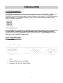
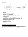
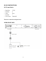
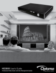
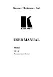
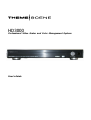
HD3000 Professional Video Scaler and Color Management System User’s Guide ABOUT THIS MANUAL This manual is designed for use with the Optoma/ThemeScene® HD3000 Video Scaler. Information in this document has been carefully checked for accuracy; however, no guarantee is given to the correctness of the contents. The information in this document is subject to change without notice. COPYRIGHT © Copyright 2006 This document contains proprietary information protected by copyright. All rights are reserved. No part of this manual may be reproduced by any mechanical, electronic or other means, in any form, without prior written permission of the manufacturer TRADEMARKS All trademarks and registered trademarks are the property of their respective owners. FCC COMPLIANCE This device complies with Part 15 of the FCC Rules. Operation is subject to the following two conditions: (1) This device may not cause harmful interference, and (2) This device must accept any interference received, including interference that may cause undesired operation. CE COMPLIANCE This device complies with CE directive FEDERAL COMMUNICATIONS COMISSION (FCC) STATEMENT This equipment has been tested and found to comply with the limits for a Class B digital device, pursuant to part 15 of the FCC Rules. These limits are designed to provide reasonable protection against harmful interference in a residential installation. This equipment generates uses and can radiate radio frequency energy and, if not installed and used in accordance with the instructions, may cause harmful interference to radio communications. However, there is no guarantee that interference will not occur in a particular installation. If this equipment does cause harmful interference to radio or television reception, which can be determined by turning the equipment off and on, the user is encouraged to try to correct the interference by one or more of the following measures: · Reorient or relocate the receiving antenna. · Increase the separation between the equipment and the receiver. · Connect the equipment to an outlet on a circuit different from that to which the receiver is connected. · Consult the dealer or an experienced radio/TV technician for help. WEEE Disposal of old Electrical & Electronic Equipment (Applicable throughout the European Union and other European countries with separate collection programs) This symbol found on your product or on its packaging, indicates that this product should not be treated as household waste when you wish to dispose of it. Instead, it should be handed over to an applicable collection point for the recycling of electrical and electronic equipment. By ensuring this product is disposed of correctly, you will help prevent potential negative consequences to the environment and human health, which could otherwise be caused by inappropriate disposal of this product. The recycling of materials will help to conserve natural resources. This symbol is only valid in the European Union. If you wish to discard this product, please contact your local authorities or dealer and ask for the correct method of disposal. -2- TABLE OF CONTENTS INTRODUCTION RECOMMENDATIONS SUPPLIED COMPONENTS INSTALLATION SYSTEM REQUIREMENTS INPUT CONFIGURATIONS CONNECTING HD3000 TO AV RECEIVER ESTABLISHING INITIAL OUTPUT RESOLUTION SYSTEM CONNECTIONS WALL MOUNTING REMOTE CONTROL FRONT CONTROL PANEL SETUP OPERATIONS AND CONTROLS OSD STRUCTURE INITIAL SETUP INTIAL ADJUSTMENTS IMAGE ADJUSTMENT ISF MODES USER MODES DISPLAY SETTINGS IMAGE SHIFT ADJUSTMENT ZOOM ADJUSTMENT EDGE MASKING ADVANCED ADJUSTMENTS SYSTEM ADJUSTMENTS FIRMWARE UPGRADES SPECIFICATIONS PRODUCT HIGHLIGHTS AND FEATURES CONNECTOR DETAILING COMPATIBILITY RS 232 INSTRUCTIONS IMPORTANT SAFETY INSTRUCTIONS APPENDICES -3- 4 5 6 7 7 7 8 11 13 14 15 16 17 18 18 21 25 29 31 32 33 35 36 37 39 51 54 55 55 56 57 58 59 61 INTRODUCTION The Optoma/ThemeScene® HD3000 is a fully-featured, all digital, video processor with advanced Scaling functions designed to enhance and improve all video signals. As home theater technology advances, the role of the video processor has evolved into an integral component in the home theater. The HD3000 provides the best in source content switching, image de-interlacing, image scaling, and color management – in one easy to use package! Optoma/ThemeScene® designed the HD3000 to be the center of you home theater entertainment center. By extensively using HDMI connections as well as a number of other industry standard inputs, all content sources are easily routed through the HD3000. With unparalleled scaling and image de-interlacing, the HD3000 goes well beyond the scope of other traditional video processors. Each video source can be fine tuned to provide the best combination for your viewing enjoyment. Features Highlights • Complete 10-bit video processing (decoding, de-interlacing, scaling, image enhancement and color management) • Gennum VXP video processor chip • Studio-grade 480i/576i Standard Definition de-interlacing and 1080i High Definition de-interlacing • Optimized scaling for each input/output resolution pairing • Dedicated color management chipset • 3 x HDMI input, 4 x Components input (2 x RCA and 2 x BNC), 3 x S-Video and 3 x Composite inputs • Unique HDMI switching that outputs HDMI audio to HDMI-capable A/V receiver • Front panel inputs for camcorder, portable computer and other video sources • Advanced video enhancement engines including: Vivid Color Engine – Provides RGBCYM saturation/hue enhancement over 9 regions independently for each color Edge Sharpening Engine – Advanced user-definable, boundary-limiting function maximizes edge enhancement Auto Contrast Engine – Scene-dependent black and white enhancement for greater picture contrast Adaptive Noise Reduction Engine – Scene-specific noise reduction removes unwanted image noise without affecting detail or sharpness Image Gamma Engine – Users can define their own gamma curve in 9 regions -4- RECOMMENDATIONS It is best to get the video content in its original form without any processing, and feed it to the HD3000 for de-interlacing, scaling and enhancement. For example, we would recommend users to use an HDMI DVD that is capable of outputting digital 480i/576i, and feed it to the HD3000 via HDMI input. In this way, the original digital video will stay intact until the HD3000 unleashes its studio grade video processing engines. In general, we recommend the following: • If possible, use digital output (DVD, D-VHS, DTV setup box, …etc). If there is no digital output, use the component output terminals (YPbPr) with short, good quality components cables. • If you are not sure about the quality of the internal de-interlacing or Scaler of your DVD, let the HD3000 do the processing by connecting it to the interlaced component output. • Some HDTV STB have scaling conversion that will output 1080i in 720p format. Try setting the STB to its native 1080i signal format and let the HD3000 perform de-interlacing and scaling. • Some HDMI DVD do not have digital interlaced output (480i/576i), we suggest users try 480p/576p first, followed by 720p and 1080i, and then users can judge from the image quality to stay with one format. • Many high end DVD players with analog output also come with high quality DAC with 12 or 14 bits of processing. Again, user should try their 480i/576i output to the HD3000 first. • HD3000 has BNC connectors for components, if you plan to use analog component to connect to a video source, you should use these BNC terminals whenever possible. • For connecting to Laser Disc player or S-VHS deck, we suggest you use the S-video output connection to connect to the HD3000. • It is best to have separate power outlet for audio and video equipment. -5- SUPPLIED COMPONENTS The product ships standard with the accessories & items show below. If anything is missing or damaged, please contact your dealer immediately. HD3000 Video Scaler • Color: Anodized Black • Weight: 9.2 Lbs • Dimension: 17.0” (W) x 11.4” (D) x 2.5” (H) 433 (W) x 285 (D) x 65 (H) mm Accessories • User Manual x 1 • Remote control x 1 • 2 x AAA Batteries • IR module x 1 • Warranty Card x 1 • AC Power cord x 1 • HDMI to HDMI cable to display (2m) x 1 • HDMI to HDMI pass-through cable (15cm) x 1 • RCA to BNC connection adapters x 5 • RS-232 cable (1.8m) x 1 -6- INSTALLATION SYSTEM REQUIREMENTS The HD3000 is designed to provide the best possible image to a high definition display, such as Optoma/ThemeScene® Home Theatre DLP projector or others. By utilizing HDMI or DVI/HDCP inputs on the display device, the video stream is fully digital. The HD3000 supports High Resolution DLP Projectors, Plasma TVs or LCD TVs with the following native High Definition Display resolutions: · 1024x768 · 1280x720* · 1280x768 · 1366x769 · 1920x1080* * HD-ready Standard Not all displays or projectors are capable of receiving and displaying this complete list of resolutions. Please refer to the documentation that came with your projector or display for the exact compatibility match. Certain versions of the HD3000 have been factory preset to a single output range. INPUT CONFIGURATIONS • Front Panel 1. VGA 2. S-video (NTSC, PAL and SECAM) 3. Composite (NTSC, PAL and SECAM) -7- BACK PANEL 4. AC IN 5. Composite 1 (NTSC, PAL and SECAM) 6. Composite 2 (NTSC, PAL and SECAM) 7. S-video 1 (NTSC, PAL and SECAM) 8. S-video 2 (NTSC, PAL and SECAM) 9. Component YPbPr/BNC 1 (480i/p, 576i/p, 720p and 1080i) 10. Component YPbPr/BNC 2 (480i/p, 576i/p, 720p and 1080i) 11. DC 12V OUTPUT 12. DC 12V OUTPUT 13. YPbPr/RGBHV 1 (480i/p, 576i/p, SCART RGB (RGBs), 720p and 1080i) 14. YPbPr/RGBHV 2 (480i/p, 576i/p, SCART RGB (RGBs), 720p and 1080i) 15. HDMI 1 (480i/p, 576i/p, 720p and 1080i) 16. HDMI 2 (480i/p, 576i/p, 720p and 1080i) 17. HDMI 3 (480p, 576p, 720p, 1080i) 18. HDMI TO AV RECEIVER 19. HDMI FROM AV RECEIVER 20. TO DISPLAY 21. RS232 22. IR Module CONNECTING THE HD3000 TO AV RECEIVER For maximum flexibility when integrating into an existing entertainment systems, the HD3000 Video Scaler is equipped with 2 HDMI outputs. One output directly sends signal out to the display and the second will send signal out to an HDMI equipped AV receiver There are three ways to connect the HDMI output from the HD3000 Video Scaler. -8- Option 1 Using the HD3000 Video Scaler as a video source selector and HDMI equipped AV Receiver for audio: If you have an HDMI equipped AV receiver and wish to send the audio signal to the receiver, but utilize the HD3000 as the video source selector: 1) Connect the video sources to the HD3000 2) Attach an HDMI cable to the “To AV Receiver” port on the back of the HD 3000. Connect the other end to your AV Receiver. This will allow the audio signal to be controlled by the AV Receiver. 3) Attach a 2nd HDMI cable to the AV out port on the back of the AV Receiver. Connect the other end to the “From AV Receiver” on the back of the HD3000. This will return the video signal in a “pass through” mode. 4) Finally, connect an HDMI Cable to the “To Display” on the back of the HD3000. Connect the other end to your display. Option 2 Using the HD3000 as video source selector and directly connecting the video source to the AV Receiver: If you do not have an HDMI equipped AV receiver, to ensure proper audio connections, you will need to directly connect the Audio out from the Video source to your receiver. The HD3000 will be used only to process the Video signals -9- 1) Connect the video sources to the HD3000 2) Connect the video sources audio out directly to your receiver 3) Attach the short HDMI cable that comes standard with the unit to the “To AV Receiver” port on the back of the HD 3000. Connect the other end to the “From AV Receiver” port on the back of the HD3000. This will allow the video signal to be properly managed. 4) Finally, connect an HDMI Cable to the “To Display” on the back of the HD3000. Connect the other end to your display. Option 3 If you have a single HDMI source, you can hook the Video source directly up to the “From AV Receiver” port on the back of the HD3000. Connect a second HDMI cable to the “To Display” port on the back of the HD3000 and attach the other end to your Plasma TV or Projector display system. - 10 - ESTABLISHING INITIAL OUTPUT RESOLUTION From the factory, the HD3000 is shipped with the default output resolution of 1280x720, progressive scan, commonly knows as 720p. This is a resolution format commonly found on many high definition digital displays. For most high definition display products, this is the only step needed. If your display is not compatible with 720p resolution, the HD3000 offers an easy way for to set the right output signals that match your display. Prior to connecting the HD3000 to a display, please determine resolution capabilities of your Display. To determine the resolution that will work, please refer to the list of compatible resolutions below: • 1280x720p 50*/60*/72 Hz (default 50Hz for European product and 60Hz for US and ASIA) • 1024x768p 50/60/72 Hz (Native resolution for a few 16x9 Plasma TV) • 1280x768p 50/60/72 Hz (Native resolution for some DLP projector, LCD TV and plasma TV) • 1366x768p 50/60 Hz (Native resolution for 16x9 plasma TV) • 1920x1080p 48/50*/60* Hz * HD ready Standard To avoid multiple processing of the same images, we recommend outputting “native” resolution to your display from the HD3000. This will ensure the best possible image quality. Many displays also feature a built-in Scaler unit – but these Scalers are not as sophisticated as the HD3000. - 11 - o Change the Output Resolution: If your display native resolution is not the HD3000’s default 720p, 1280x720, change the resolution as follows: STEP 1: Connect the HD3000 to your display (see Pg 12) and power on the HD3000 and your display. Option 1: If your display is capable of 1280x720, the display will lock on to the output signal from the HD3000. Press the menu button on the remote control and use the OSD (On Screen Display) to change to your desired native display resolution. (See Operation & Control section of this manual) Option 2: If your display cannot lock on to 720p, you will not be able to utilize the OSD to change the initial settings. In this case, use the front panel control buttons, and press the “↑” key. This will automatically start changing the resolution output from the HD3000. Press the button until you find a mode that will work. Please remember to wait a few seconds between button presses to allow for the HD3000 & the display to synchronize. Once a mode is found, the HD3000 will prompt you for a confirmation. All other setup will be done with the remote control, via the Menu button. STEP 2: If your display cannot lock on to 1280x720 a) Use the front panel control buttons, press “_” key one at a time. Each pressing of the HD3000 will change its output resolution from the table shown above. Please allow for a few seconds for display to try to lock on to the changed output resolution. b) Once the desired resolution is found, the HD3000 will ask you for confirmation, or it will return to 1280x720 default resolutions. - 12 - SYSTEM CONNECTIONS • Front Panel • Back Panel - 13 - WALL MOUNT SETUP The HD3000 will be installed into a variety of environments – and it has been designed to take in this into consideration. The HD3000 can be mounted directly to a wall. Please contact your dealer for mounting options. Step 1 Please purchase suitable holder – the HD3000 supports 2 different mounting bracket sizes. Step 2 Please use screws to fix the HD3000 and the holder. Step 3 Then you may follow up the usage instruction of holder to lock the HD3000 on the wall. - 14 - REMOTE CONTROL Remote Control and Buttons - 15 - FRONT CONTROL PANEL Many basic adjustments can be made with the buttons found inside the door on the front panel. Please refer to the diagram below for further information. 1. Left: 2. Down: 3. Up: 4. Right/Re-sync: 5. Menu/Exit: 6. Enter/Source: Move left in the OSD menu Move down in the OSD menu Move up in the OSD menu Move right in the OSD menu. Press this button to re-sync the display device Press this button to enter the OSD. While in the OSD, press this button to exit the OSD Press this button to select setting while in the OSD. Press while outside of the OSD to search sources - 16 - SETUP HD3000 was designed to provide maximum flexibility and image configuration options. Each video input signals has its own memory to store adjustment parameters. • Different input sources can be attached to the same port on the HD3000 and each source can be considered and “independent” signal. Each port has 4 memory “slots” which can be calibrated and stored independently. For example a single HDMI input on the HD3000 could be calibrated for a 480i, 576i, 720P and 1080i. Each signal can be fine tuned according to its own characteristics and according to user’s own preferences. To maximize your experience, once all video sources are connected to the HD3000, we recommend performing a SETUP procedure for each signal. This will set and store in the system memory all configuration parameters for image optimization. Daily management of the video contents is best done by the OSD IMAGE features. - 17 - OPERATIONS AND CONTROLS OSD STRUCTURE There are four main modules in the OSD: IMAGE, DISPLAY, SYSTEM, and SETUP: • IMAGE enables a powerful interface to tune the picture to the best quality possible • DISPLAY provides the ability to set the different scaling formats, both input and output • SYSTEM contains other system oriented functions, such as language,output resolution changing, and more • SETUP configures video inputs IMAGE DISPLAY SYSTEM - 18 - SETUP IMAGE Mo de Contrast Noise Reduction Brightness Color Tint Edge Enhancement Color Temp. Gamma Sharpness Image Mode Reset Current Advanced B/W Extension Reset Color Vividness DISPLAY Format Edge Masking H Zoom V Zoom Image Shift SYSTEM Language Source Background Output Resolution - 19 - 12V Trigger Factory Reset SETUP S ig n a l Auto Calibration Y Gain Pb Gain Pr Gain Y Bias Pb Bias Pr Bias For Component YPbPr Signals SETUP S ig n a l White Level Black Level Saturation Hue CTI For Video Signals SETUP S ig n a l White Level Black Level For Analog RGB Signals - 20 - Reset DNR Reset Reset INITIAL SETUP • • • During the initial setup, adjustment of the color and image quality should be performed. After this initial setup is the completed, the HD3000 will automatically store the settings for optimal image viewing. The HD3000 OSD is dependent upon the video source signal. It has been designed to show a different OSD display with each input. Please refer to table A and B below for more details on available adjustments for each signal. With the exception of the VGA and BNC connections, if the HD3000 is not receiving a signal from the input source device, the OSD will only allow the System Setup module to be adjusted. Note: Please exercise caution when adjusting the “Horizontal” and “Vertical” as this may cause the loss of your image, if the values are set out of range. We recommend using this adjustment only if you cannot receive input signal. - 21 - 1. Press the “Menu” button on the remote to show the Menu. Use “↑”, “↓” arrow keys to select SETUP category, press “Enter” or “→” key to enter this adjustment category. 2. The first line shows the current signal. Use “→”, arrow key to select the item “Signal”; User may see different items for adjust depending on the current signals. - 22 - 3. Press “Enter” key or “→” key to enter category. The OSD shows a signal submenu according to current signal. 4. Press “Enter” key or “→” key to enter item. An option bar shows according to current signal. Please refer to the following examples. 5. For three items (Type, Pedestal and Color Space) use “←”, “→” arrow keys to select the desired choices, then press “Enter” to confirm the items. For the rest of the items (Horizontal, Vertical, Frequency and Phase) use “←”, “→” arrow keys to adjust the slider bar to achieve the desired effects, then press “Enter” to confirm the items. Please also refer to the table A & B for the range of available values. Type This function is only for BNC signals. The default choice, AUTO, automatically detects the signal type. The other three choices (YPbPr, RGBHV, RGB) force the HD3000 to display the selected signal type. Pedestal Black level control: All connected devices besides HDMI can choose between 2 pre-sets: 0 IRE or 7.5 IRE. HDMI devices are given the choice of DVI-PC or DVI-Video; DVI-PC corresponds to 0 IRE and DVI-Video corresponds to 7.5 IRE. - 23 - Color Space The default choice, AUTO, automatically detects the color space used. The other two choices (SDTV, HDTV) force the HD3000 to use the color space mapping associated with SDTV or HDTV. Other Choices: Horizontal Vertical Frequency Phase - 24 - INTIAL ADJUSTMENTS Auto Calibration The HD3000 features and “Auto Calibration” feature. This will automatically optimize and adjust the video image. 1. Activate the OSD by pressing the “Menu” button. 2. Use “↑”, “↓” arrow keys to select SETUP category, press “Enter” or “_” key to enter this adjustment category. 3. Use “↑”, “↓” arrow keys to select the desired adjustment item (as shown): 4. Press “Enter” or “→” to enter this item. The Menu disappears and a small bar appears as shown below: 5. Use “←”, “→” arrow keys to turn on or off the auto calibration. 6. Once the “Auto Calibration” is activated, the HD3000 calibrates and fine tunes the image for optimal performance. - 25 - S Video and Composite Video This section explains the operation of SETUP when inputting S-Video or Video/CVBS signals. 1. Enter SETUP as described in previous section and Menu will be shown as below. 2. Use “↑”, “↓” arrow keys to select the adjustment item, press “Enter” key or “→” key to enter this item. The Menu disappears and a small bar appears as shown below: 3. Use “←”, “→” arrow keys to calibrate. - 26 - Component YPbPr This section explains the operation of SETUP when inputting Component YPbPr signals. 1. Enter SETUP as described in previous section and the Menu is shown as below: 2. Use “↑”, “↓” arrow keys to select the adjustment item, press “Enter” key or “→” key to enter this item. The Menu disappears and a small bar appears as shown below. 3. Use “←”, “→” arrow keys to calibrate. - 27 - Analog RGB This section explains the operation of SETUP when inputting Analog RGB signals (PC). 1. Enter SETUP as described in previous section and the Menu is shown as below: 2. Use “↑”, “↓” arrow keys to select the adjustment item, press “Enter” key or “→” key to enter this item. The Menu disappears and a small bar appears as shown below: 3. Use “←”, “→” arrow keys to calibrate. - 28 - IMAGE Adjustment The IMAGE adjustment module allows the user to tailor the image to their particular taste, such as the frequently-used items, like Contrast, Brightness, Color, Tint and Sharpness. For advanced users, there is an “Advanced …” submenu, which contains more options for image fine-tuning. All function may be operated by the remote control as shown below. The “Up”, “Down”, “Left”, “Right”, “Enter” are the key buttons for control. 1. Press the “Menu” button on the remote to show the Menu. 2. Use “↑”, “↓” arrow keys to select IMAGE category, press “Enter” or “→” key to enter this adjustment category as shown below 3. Once user chooses User 1, 2 or 3, user can adjust each item (Contrast, Brightness, Color, Tint, Sharpness, and Advanced) of IMAGE and SETUP per current signal/connector chosen by user. Therefore users have five modes setups for each signal/connector - 29 - 4. Use “↑”, “↓” arrow keys to select the desired adjustment item, press “Enter” key or “→” key to enter this adjustment item. The OSD disappear and only show a small adjustment bar appears. 5. To adjust other adjustment items, use “↑”, “↓” key to move to other adjustment items. 6. When the adjustment is finished, press “Menu” button to exit the adjustment and go back to Menu. 7. With five different setups user can directly choose any one by pressing buttons (ISF Day, ISF Night, User1, User2 and User3) on remote control. - 30 - ISF Modes For care-free operation, the HD3000 comes with ISF Modes. The HD3000 is designed to offer exceptional performance "out of box"; but since lighting and other factors can affect the performance of your display device, the HD3000 offers ISF calibration capability. After the ISF calibration, the user can simply switch among the two ISF Day and Night modes to have certified image effects. Day and Night modes are locked at the factory and require certified ISF calibrators to unlock and set-up. Certain factors cannot be set at the factory due to variables in the setup. Professional calibration of Day and Night modes allow for appropriate setting of contrast, tint, sharpness, color levels and other parameters to exactly match the environment where the display device is used. There are also three user modes which can be modified by the user, allowing a total of five settings per signal/connection to match every condition. For ISF calibration, please visit www.imagingscience.com to find a certified ISF technician in your area. 1. To select a ISF mode, press “Menu” button and use “Enter” or “→” to enter the IMAGE category, then use “↑”, “↓” arrow keys to highlight “Mode”. Press “Enter” or “→” to enter ISF Mode menu. 2. Use “←”, “→” arrow keys to select the desired mode. - 31 - User Modes There are three user modes. All fine-tuning under User Modes will be saved for each signal/connection. 1. To select a User mode, press “Menu” button and use “Enter” or “→” key to enter the IMAGE category, then use “↑”, “↓” arrow keys to highlight “Mode”. Press “Enter” or “→” key to enter User Mode. 2. Use “↑”, “↓” arrow keys to select the desired User Mode. 3. There are three user modes: User1, User2 and User3, each mode can be fine tuned for the desired image performance. The adjustable parameters include Contrast, Brightness, Color, Tint, and Sharpness. - 32 - DISPLAY SETTINGS Aspect Ratio Adjustment • To fit the input image to the correct aspect ratio, six modes can be selected: 16:9, 4:3, Native, Format 1, 2 and 3. • Default modes are 16:9, 4:3 and Native. • At this time, the exact aspect rations for Format 1, 2 and 3 have not been defined. For maximum flexibility, Format 1 and 2 are pre-set as 16:9 mode and Format 3 is pre-set as Letter Box. Format 3 stretches the input image vertically to remove the top and bottom black areas in 2.35 movies. • Native mode is one to one pixel mapping and will match the input image. • User also can quickly select each mode on from the remote control by pressing the “Display Format” button. 1. Press the “Menu” button on the remote to show the Menu. 2. Use “↑”, “↓” to select DISPLAY category and press “Enter” or “→”, then use “↑”, “↓” to highlight the “Format” adjustment item: - 33 - 3. Press “Enter” key or “→” key to enter this adjustment item. The Menu disappears and only a small options bar is shown: 4. Use“↑” or “↓” arrow keys to choose the desired format. 5. Once you select Format 1, 2 or 3 on the “Display” menu, any other adjustments to the display that are made can be saved upon the exit of the “Display” mode. A reminder window will appear asking for confirmation. 6. User can save settings in the Format 1, 2, 3, or choose “Exit/Not Saved” to give up the settings. Once user selects “Not Saved”, the settings are still temporary and kept until user changes aspect ratio, signal/channel or restart the HD3000. - 34 - IMAGE SHIFT ADJUSTMENT The HD3000 has the ability to adjust the image position and size to optimize its location on your display by using of both an Image Shift and Image Zoom feature. The function Image Shift can shift the input image up, down, left and right up to 100 pixels in each direction. 1. Press the “Menu” button on the remote to show the Menu. 2. Use “↑”, “↓” arrow keys to select DISPLAY category, press “Enter” or “→” key to enter this category. Use “↑”, “↓” arrow keys to highlight the “Image Shift” adjustment item as shown below: 3. Press “Enter” or “→” to enter this adjustment item. A small adjustment bar is shown, and the user may use the “Up”, ”Down”, “Left” and “Right” keys to move the image to best fit the display device screen. 4. Press the “Shift” button on the remote control to vertically shift the image as well. No horizontal shift is possible from the remote control. - 35 - ZOOM ADJUSTMENT The HD3000 provides 1.5x zoom in the horizontal direction and 1.2x zoom in the vertical direction. 1. For Zoom, user can select H Zoom (Horizontal) or V Zoom (Vertical) to adjust separately. Select H Zoom or V Zoom on Menu to enter adjust bar. 2. An adjust bar is shown. To use “←” arrow key to zoom out and “→” arrow key to zoom in. Maximum values are 150% for H zoom and 120% for V zoom. For ease of use, the zooming effect is shown immediately. *Please be aware that screen flashes while adjusting zoom in or out on some signals. 3. User also can adjust horizontal and vertical zoom in tandem by pressing the “Zoom” button on the remote control. Zoom adjustment percentage on the remote control is 1% of the current image per click. - 36 - EDGE MASKING User also can adjust horizontal and vertical zoom in tandem by pressing the “Zoom” button on the remote control. Zoom adjustment percentage on the remote control is 1% of the current image per click. 1. Press the “Menu” button on the remote to show the Menu. 2. Use “↑”, “↓” arrow keys to highlight DISPLAY category, press “Enter” or “→” key to enter this adjustment category Press “↑”, “↓” arrow keys to highlight the “Edge Masking” adjustment item as shown below: 3. Press “Enter” key or “→” key to enter this adjustment item. The Menu disappears and a sub menu is shown as below. 4. Use “↑”, “↓” arrow keys to select “Setting”, then press “Enter” or “→” key to enter the mask size setting. - 37 - 5. Press the buttons “↑”, “↓”, “←”, “→” to select one edge/direction (Up, Down, left or Right) for the edge mask. Press “Enter” when finished. 6. Use “↑”, “↓”, “←” or “→” arrow keys to adjust the edge size. 7. User can use “Mask Back Color” to fine-tune background color (gray level) by selecting “Mask Background color” and enter the following adjust bar. Use “←” or “→” to change each bit and use “↑”or “↓” to change values. The range of value is 0~255. - 38 - ADVANCED ADJUSTMENTS Image The HD3000 is a powerful image enhancement tool. Many advanced adjustment functions are included, such as noise reduction, gamma curves, and color temperature. These functions will help the user achieve the best image possible. For more details, please see the sections associated with each item. To access the Advanced Adjustments: 1. Press the “Menu” button on the remote to show the Menu. 2. Use “↑”, “↓” to highlight the IMAGE category, then press “Enter” or “→” to enter this adjustment category. Use “↑”, “↓” to select the “Advanced” adjustment item. 3. Press “Enter” or “→” to select this item. A menu which contains advanced adjustment items appears. - 39 - Noise Reduction The HD3000 allows for 11 levels of noise reduction, ranging from 0 to 10. 1. Enter the Advanced menu as detailed in the previous section. 2. Use “↑”, “↓” to highlight the “Noise Reduction” adjustment item, press “Enter” or “→” to select. The OSD disappear and a small adjustment bar is shown: 3. Use “←”, “→” arrow keys to select the preferred Noise Reduction setting. The value ranges from 0 to 10. A value of 0 means the noise reduction function is off. - 40 - Gamma The HD3000 comes with 10 preset gamma curves. After the initial setup and fine tuning is completed, utilize the Gamma Adjustment steps to optimize your image output. 1. Enter the Advanced menu as detailed in the previous section. 2. Use “↑”, “↓” to highlight the “Gamma” adjustment item, press “Enter” or “→” to select. The OSD disappear and a small adjustment bar is shown: 3. Use “←”, “→” to select the preferred gamma value. The value ranges from -5 to 5. A value of 0 equates to a linear gamma curve. - 41 - Image Mode For easy, care-free operation, the HD3000 comes with preset image modes. Once the front-end is correctly fine tuned in SETUP and IMAGE, user can simply switch among the pre-set modes to have different image effects. 1. Use “↑”, “↓” arrow keys to select the “Image Mode” adjustment item, press “Enter” key or “→ key to enter this adjustment item. The OSD disappear and only show a small adjustment bar (as shown below) 2. Use “←”, “→” arrow keys to select the preferred image mode. There are 3 preset modes: Film, TV, Linear and one user modes, each mode is fine tuned with a certain desired image performance. Please refer to the following description: Mode Film Description Simulate a Movie Theatre image performance, darker with great picture depth, more a “film-like” experience, suitable for a complete dark room environment. TV Normal mode is brighter, and the image is more “TV-like” Linear This mode is a by-pass mode for natural image. User User can alter - 42 - 3. User can select and setup favourite setting on “User” mode and a adjust submenu as shown in the following 4. Use “←” and “→” arrow keys to select different Input level or select “reset” function, and user may adjust output value by using “↑” or “↓” in each input level. 5. A complete gray level bar on the top of screen is shown while adjusting level; it may help user to see different effects with different value to decide a suitable value. 6. If user wants to set gamma curve as “linear”, use “←”or “→” arrow keys to move “reset” and press “enter”, then select “Yes” on confirmation notice so that the gamma curve is back as “linear”. Once user selects “reset” and gamma curve as “linear”, the setup values before are all clear without any saving. - 43 - Color Temperature The HD3000 comes with three color temperature presets. The user can switch between the presets to achieve desired image. 1. Use “↑”, “↓” arrow keys to select the “Color Temp.” adjustment item, press “Enter” key or “→” key to select this adjustment item. The Menu disappears and a small adjustment bar is shown as below: 2. Use “←”, “→” arrow keys to select default modes. 3. For User mode adjustment, put cursor on “User”, press “Enter” key to enter this adjustment item. The Menu disappears and a submenu appears as below: 4. Use “↑”, “↓” arrow keys to select the desired adjustment items, press “Enter” key or “→” key to select it. The Menu disappears and only a small adjustment bar appears: 5. Use “←”, “→” arrow keys to adjust image. - 44 - Edge Enhancement There are 5 pre-set modes and one user mode for advanced edge enhancement filter. You can easily switch between the modes to achieve different effects. 1. Use “↑”, “↓” arrow keys to select the “Edge Enhancement” adjustment item, press “Enter” key or “→” key to enter this adjustment item. The Menu disappears and a small adjustment bar is shown as below: 2. Use “←”, “→” arrow keys to select default modes. 3. For User mode adjustment, put cursor on “User”, press “Enter” key to enter this adjustment item. The Menu disappears and a sub adjustment menu appears as below: 4. Use “↑”, “↓” arrow keys to select and choose “Edge enhancement” bar, press “←”, “→” arrow keys to adjust different enhancements. 5. User can select and setup different settings for each mode (1 to 5) in “User” option and adjust the submenu as shown in the following diagram. When the user chooses one mode and presses “Enter” to see the original settings of each items, and then user may adjust value per original setting of each mode. - 45 - Press Enter to load Ref. Mode 6. The first item “Ref. mode” has five default value sets for user to fine-tune the items (High Coring, High Width, Low Coring, Low Width and Strength A &B ), user can use “←”, “→” arrow keys to select each set and press ”Enter ” to start fine-tuning. Once user changes the value of each item, the updated values are memorized. Please refer to the following description and graphics about adjusting items. 1) The vertical coordinate is the luminance offset of the selected area on the screen. A lower luminance offset means the selected area of the screen will have smoothed brightness in for items such as human skin or backgrounds. A higher luminance provides for limited enhancement. This will allow the user to set and fine tune different zones (A and B). Zone A is the primary area of enhancement while Zone B is the area for minimal or no adjustment. High Coring Luminance Offset Low Coring Enhance strength 2) Using “High Coring” and “Low Coring” to divide A and B Zones. 3) Using “Strength” A and B to have different levels of Edge enhancement. Value of Strength A must be higher than Strength B. 4) Then High width and Low width fine-tune can make settings between A and B zones smooth. High width High Coring Luminance Offset Low Coring Low width Enhance strength - 46 - Color Vividness The HD3000 includes 3 preset color management setting and one user definable setting. You can easily switch between the modes to achieve different effects. 1. Use “↑”, “↓” arrow keys to select the “Color Vividness” adjustment item, press “Enter” key or “_” key to enter this adjustment item. The Menu disappears and a small adjustment bar is shown as below: 2. Use “←”, “→” arrow keys to select default modes. 3. For User mode adjustment, put cursor on “User”, press “Enter” key to enter this adjustment item. The Menu disappears and a sub adjustment menu is shown as below: 4. Use “↑”, “↓” arrow keys to select the desired adjustment item, press “←”, “→” arrow keys to adjust image. 5. User can select and setup favourite setting on “User” and an adjust submenu shows as the following. Please refer to the following description and graphic about Saturation and Hue adjustment details. 1) Choose a color (Green, Blue, Cyan, Yellow, Magenta and Red) and move to “Saturation” or “Hue” to fine-tune. 2) Enter “Saturation” to adjust “level” (brightness level) on Lengthwise graduation from level 0 to 15, and then adjust value of Saturation from -100 to 100 in accordance with each level selected. - 47 - 3) Enter “Hue” to adjust “level”(brightness level) on Lengthwise graduation from level 0 to 15, and then adjust value of Saturation from -30 to 30 in accordance with each level selected. 4) A color level bar is shown on the top of screen for user to see the Saturation or Hue effects with different values. 5) “Reset” option in Saturation or Hue adjustment is to reset Saturation value or Hue value of all levels (0 to 15). Press “↑” arrow key while moving on level 15 or “↓” arrow key while moving on level 0 to select “Reset ” option. 6. A color level bar is shown on the top of screen for user to see color vividness effects. 7. The item “Reset” bottom of the menu is for Saturation and Hue values of current “Color” selected, a confirmation notice shows while selecting” Enter” to reset settings. - 48 - B/W Extension Black and White Extension can stretch the black and white levels to automatically increase the contrast of input image. The HD3000 has 5 pre-set modes the user can switch among the pre-set to obtain different image effects 1. Use “↑”, “↓” arrow keys to select the “B/W Extension” adjustment item, press “Enter” key or “→” key to enter this adjustment item. The Menu disappears and a small adjustment bar is shown below: 2. Use “←”, “→” arrow keys to select default modes. - 49 - Demo Mode This function provides the user with a preview window where settings such as Edge Enhancement, Color Vividness and B/W Extension can be viewed. 1. Select “Demo” and a turn on/off bar is shown as following. Using “←”, “→” arrow keys to turn on or off the function. 2. Once turning on Demo function, an oblong frame is shown. After turning on “Demo” function and with an enhanced frame pressing “↑” or “↓” arrow keys to enter and fine-tune each adjustment bar. 3. User can view immediate enhanced performances only while adjusting items: Image mode, Edge Enhancement, Color Vividness and B/W Extension. - 50 - SYSTEM ADJUSTMENTS Programmable 12V Trigger There is one 12V Trigger which can be selected on or off according to different aspect ratios. 1. Press the “Menu” button on the remote to show the OSD. 2. Use “↑”, “↓” arrow keys to select SYSTEM category, press “Enter” or “→” key to enter this adjustment category as shown below: 3. Use “↑”, “↓” arrow keys to select the “12V Trigger” item, press “Enter” key or “→” key to enter this item. The OSD disappears and a submenu appears: 4. Use “↑”, “↓”, “←”, “→” arrow keys to program the 12V Trigger output. 5. Once each format is set as on or off, 12 Trigger function turns on or off accordingly and automatically while changing format any time by user. - 51 - Output Resolution Selection The HD3000 can use Menu to change the desired output resolution. 1. Press the “Menu” button on the remote to show the Menu. 2. Use “↑”, “↓” arrow keys to select SYSTEM category, press “Enter” or “→” key to enter this adjustment category 3. Use “↑”, “↓” arrow keys to select the “Output Resolution” item as shown below: 4. Press “Enter” key or “→” key to enter this item. The Menu disappears and a sub menu is shown as below - 52 - 5. Use “↑”, “↓”, “←”, “→” arrow keys to desired output resolution and pressing “Enter” to decide the resolution. 6. If the connected device/display can’t support the output resolution user selected, a few seconds later the option bars moves back the original output resolution. 7. Once user selects and decides an output resolution, a confirmation notice is shown. Enter “Yes” or “Cancel” to adopt new selected output resolution or cancel and go back to original output resolution. - 53 - FIRMWARE UPGRADES You can download updated firmware if available on the support centre at www.optomaeurope.com Step 1: Connect PC/Notebook and the HD3000 with RS232 Cable. Step 2: Execute the update program downloaded from support centre, and follow the instructions in the update program. - 54 - SPECIFICATION PRODUCT HIGHLIGHTS AND FEATURES • • • • • • • • • • • • • • • • • • • • • • • Gennum solution, High-end 10 bits Scaler, 1080i de-interlacing ability High-end 10 bit Image Quality Enhancement LSI. Whole 10 bits Video Processing System. (Except HDMI input and output). Dual channel both with powerful 10 bits image processing ability. Channel A&B front end: 10 bits integrated multi-format video decoder and RGB graphics digitizer Input: 3 HDMI input for HDMI signal switching, ¾ 1 HDMI-in from AV receiver, ¾ 2 YPbPr through RCA connector, ¾ 2 YPbPr/RGBHV through BNC connector, ¾ 1 VGA-in through Dsub-15 connector ¾ 3 S-video, ¾ 3 composite Output: 1 HDMI output (To AV receiver) ¾ 1 HDMI output (To display), with configurable output timing to four modes ¾ 1024X576p, 50Hz ,1024X576p, 60Hz, 1024X576p, 72Hz ¾ 1024X768p, 50Hz ,1024X768p, 60Hz, 1024X768p, 72Hz ¾ 1280X720p, 50Hz, 1280X720p, 60Hz, 1280X720p, 72Hz ¾ 1280X768p, 50Hz, 1280X768p, 60Hz, 1280X768p, 72Hz ¾ 1366X768p, 50Hz, 1366X768p, 60Hz ¾ 1920x1080p, 48Hz, 1920x1080p, 50Hz, 1920x1080p, 60Hz Two programmable 12V trigger, RS-232C: 1 RS232C Dsub-9Pin connector. IR: 1 front built-in IR sensor and 1 external IR module through phone jack. Keypad : Power, Menu/Exit, Enter/Source, Up, Down, Left, Right/Resync The key of remote controller: 40 keys Weight: around 9.2 Lbs ID Color: Anodized Black Unit dimension (W X D X H): 433X285X50 (mm) (not include height of feet) Control keypad: Power, Menu/Exit, Enter/Source, Up, Down, Left, Right/Resync Power indicator lights: “Power On”: Blue “Stand by”: Red Materials: Top cover, Lateral panel and front bezel are made of aluminium. Base is made of iron. IR receivers: Front of HD3000 and one set of extra IR module. Power Supply: Input is 90 - 264V_ AC, 47-63 Hz, and power consumption up to 45W. Temperature/Humidity ¾ Operating: 5~40°C, 80% RH (Max) non-condensing ¾ Storage: -10~60°C, 80% RH (Max) non-condensing Altitude: Operating: 0~2,500 ft 5°C~35°C 2,500~5,000 ft 5°C~30°C Storage: 40,000 ft Electrical/Environmental listings: FCC, CE, UL/CUL, TUV-GS, and CB report. - 55 - CONNECTOR DETAILING Input Connectors: Video 1: CVBS. Video 2: CVBS. Video 3: CVBS. S-Video 1: S Video. S-Video 2: S Video. S-Video 3: S Video. HD1: YPbPr through RCA connectors. Supports 480i/576i, 480p/576p, 720p, 1080i. HD2: YPbPr through RCA connectors. Supports 480i/576i, 480p/576p, 720p, 1080i. HD3: YPbPr through BNC connectors with HV BNC connectors. Supports 480i/576i, 480p/576p, 720p, 1080i, and SCART RGB. • HD4: YPbPr through BNC connectors with HV BNC connectors. Supports 480i/576i, 480p/576p, 720p, 1080i, and SCART RGB. • HDMI1: Receive from HDMI source and then switch to HDMI-out (To AV receiver) connector. • HDMI2: Receive from HDMI source and then switch to HDMI-out (To AV receiver) connector. • HDMI3: Receive from HDMI source and then switch to HDMI-out (To AV receiver) connector. • HDMI-in (From AV receiver) : Supports (1)Video: 720 x 480i@50/60Hz, 640 x 480p@50/60Hz, 720 x 480p@50/60Hz, 720 x 576i@50Hz, 720 x 576p@50Hz, 1280 x 720p@50/60Hz, 1920 x 1080i@50/60Hz • • • • • • • • • (2)Audio: Linear PCM audio. • VGA-in: Output Connector: • HDMI-out (To AV receiver): Switch 3 HDMI source to one HDMI output, this output can be connected to “AV receiver” device or HDMI-in (From AV receiver) connector. ¾ HDMI-out to display device Other connectors: • RS232: one connector for firmware upgrading and debugging and remote control - 56 - COMPATIBILITY Computer compatibility (Analog) Compatibility Resolution V-Sync [Hz] H-Sync [KHz] VGA 640x480 60 31.5 640x480 72 37.9 640x480 75 37.5 US TEXT 720x400 70 31.5 SVGA 800x600 56 35.2 800x600 60 37.9 800x600 72 48.1 800x600 75 46.9 1024x768 60 48.4 1024x768 70 56.5 1024x768 75 60.0 848x480 60 31.1 1280x720 60 45 1280x768 60 48 1280x768 75 60.1 1366x768 60 48.1 XGA Wide Video Compatibility Standards: • NTSC - NTSC M/J, NTSC 4.43 • PAL - PAL B/D/I/G/H, PAL M, PAL N • SECAM - SECAM B/D/G/K/L • SDTV - 480i, 480p, 576i, 576p, • HDTV - 720p, 1080i - 57 - RS 232 INSTRUCTIONS RS 232 specification • Baud Rate: 57600 • Data Bits: 8 • Parity: None • Stop Bits: 1 • Flow Control: XON/XOFF Please see connections diagram below. HD3000 FRONT PANEL - 58 - IMPORTANT SAFETY INSTRUCTIONS WARNING RISK OF ELECTRIC SHOCK DO NOT OPEN WARNING: To reduce the risk of electric shock, DO NOT remove cover or back. No user-serviceable parts inside. Refer servicing to qualified service personnel. This symbol is intended to alert the user to the presence of un-insulated "dangerous voltage" within the product's enclosure that may be of sufficient magnitude to constitute a risk of electric shock to persons. This symbol is intended to alert the user to the presence of important operating and maintenance (servicing) instructions in the literature accompanying the appliance Important Safety Instructions For Your Display 1. Read and apply the operating instructions provided with your display. 2. Read all of the instructions given here and retain them for later use. 3. Follow all warning and instructions marked on the display. 4. WARNING: To reduce the risk of fire or electric shock, do not expose this appliance to rain or moisture. 5. Caution: To prevent electric shock do not use this (polarized) plug with a receptacle or other outlet unless the blades can be fully inserted to prevent blade exposure. 6. Unplug this processor from the wall outlet before cleaning. Do not use liquid or aerosol cleaners. Use a damp cloth for cleaning. 7. Do not use attachments/accessories not recommended by the manufacturer as they may cause hazards. 8. Do not use this processor near water. For example: avoid placing it in or near a bathtub, kitchen sink, laundry tub, wet basement, swimming pool, etc. 9. Do not place this processor on an unstable cart, stand or table. The processor may fall, causing serious injury to a child or adult and serious damage to the appliance. Use only with a cart or stand recommended by the manufacturer, or sold with the processor. 10. An appliance and cart combination shall be moved with care. Quick stops, excessive force, and uneven surfaces may cause the appliance and cart combination to topple. 11. Slots and openings in the cabinet and the back or bottom are provided for ventilation, to insure reliable operation of the display and to protect it from overheating. These openings must not be blocked or covered. There should be at least 2-inches of clearance from these openings. Never block the openings by placing the processor on bed, sofa, rug or other similar surface. Never place this processor near or over a radiator or heat register. 12. Operate only from the type of power source indicated on the marking label. If you are not sure of the type of power supplied, contact your television dealer or local power company. 13. This processor is equipped with a polarized alternating-current line plug (a plug having one blade wider than the other). This plug will fit into the power outlet only one way. This is a safety feature. If you are unable to insert the plug fully into the outlet, try reversing the plug. If the plug still doesn’t fit, contact your electrician to replace your obsolete outlet. Do not defeat the safety purpose of the polarized plug. 14. Do not allow anything to rest on or pinch the power cord. Do not locate this processor where the cord could be stepped on. 15. Do not overload wall outlets and extension cords as this can result in fire or electric shock. - 59 - 16. Never push objects of any kind into this processor through cabinet openings. This could result in a fire or electric shock. Never spill liquid of any kind on the processor. 17. If an outside antenna is connected to the television equipment, be sure the antenna system is grounded 18. 19. 20. 21. 22. 23. so as to provide some protection against voltage surges and built up static charges. In the U.S., Section 810 of the National Electrical Code provides information with respect to proper grounding of the mast and supporting structure, grounding of the lead-in wire to an antenna discharge unit, size of grounding conductors, location of antenna-discharge unit, connection to grounding electrodes, and requirements for the grounding electrodes. For additional safety during a lightning storm, or when it is left unattended and unused for long periods of time, unplug it from the wall outlet and disconnect the antenna. This will prevent damage to the receiver due to lightning and power-line surges. An outside antenna system should not be located in the vicinity of overhead power lines or other electric light or power circuits, or where it can fall into such power lines or circuits. When installing an outside antenna system extreme care should be taken to avoid touching any power lines or circuits as contact with them could cause fatal injuries. Unplug this processor from the wall outlet and refer servicing to qualified service personnel under the following conditions: a. When the power cord or plug is damaged or frayed. b. If liquid has been spilled into the display. c. If the processor has been exposed to rain or water. d. If the processor does not operate normally by follow the operating instructions. Adjust only those controls that are covered by the operating instructions as improper adjustment of other controls may result in damage and will often require extensive work by a qualified technician to restore the processor to normal operation. e. When the processor exhibits a distinct change in performance, have it serviced by an authorized service provider. Do not attempt to service this processor yourself as opening or removing covers may expose you to dangerous voltage or other hazards. Refer all servicing to qualified service personnel. When replacement parts are required, be sure the service technician uses replacement parts specified by the manufacturer that have the same characteristics as the origin part. Unauthorized substitutions may result in fire, electric shock, or other hazards. Upon completion of any service or repairs to this processor, ask the service technician to perform routine safety checks to determine that the processor is in safe operating condition. - 60 - APPENDICES Optoma Global Office For service or support please contact your local office USA 715 Sycamore Drive Tel : 408-383-3700 Milpitas, CA 95035, USA Fax: 408-383-3702 www.optomausa.com Service : [email protected] Canada 120 West Beaver Creek Road Unit #9 Richmond Hill, ON L4B 1L2, Canada Tel : 905-882-4228 Fax: 905-882-4229 www.optoma.com Europe 42 Caxton Way, Watford Business Park Watford, Hertfordshire, WD18 8QZ, UK Tel : +44 (0) 1923 691 800 Fax: +44 (0) 1923 691 888 www.optomaeurope.com Service Tel : +44 (0)1923 691865 Service : [email protected] Taiwan 5F., No. 108, Minchiuan Rd. Tel : +886-2-2218-2360 Shindian City, Taipei Taiwan 231, Fax: +886-2-2218-2313 R.O.C. www.optoma.com.tw Service : [email protected] Hong Kong Unit 901, 9/F., Vogue Centre, No. 696 Castle Peak Road, Kowloon, Hong Kong Tel : +852-2396-8968 Fax: +852-2370-1222 www.optoma.com.cn China 5F, No. 1205, Kaixuan Rd., Tel : +86-21-62947376 Changning District Fax: +86-21-62947375 Shanghai, 200052, China www.optoma.com.cn Latin America 715 Sycamore Drive Tel : 408-383-3700 Milpitas, CA 95035, USA Fax: 408-383-3702 www.optoma.com.br www.optoma.com.mx - 61 -