1
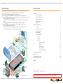
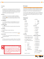
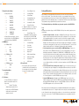
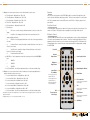
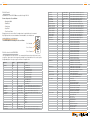
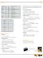
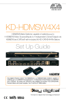
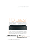
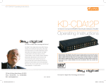
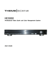
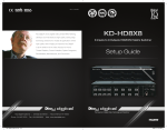
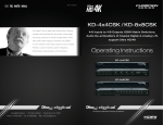
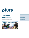
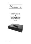
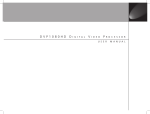
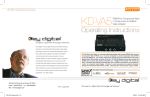
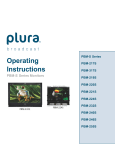
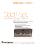
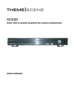
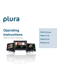
KD-VP2500
Digital Video Processor and Switcher
Operating Instructions
Key Digital®, led by digital video pioneer Mike Tsinberg,
develops and manufactures high quality, cutting-edge
technology solutions for virtually all applications where
high quality video imaging is important. Key Digital®
is at the forefront of the video industry for Home
Theater Retailers, Custom Installers, System Integrators,
Broadcasters, Manufacturers, and Consumers. We
provide total video system solutions because we
know and help drive the technology, the industry, the
business, and all the latest up-and-coming standards.
But most of all, we know exactly what you need for your
unique application - the right solution.
The KD-VP2500 is a full-featured video processor and switcher in one compact package.
The KD-VP2500 is equipped with varied digital and analog video and audio input and
output formats available on a full array of connectors. It is capable of driving all popular
HD and SD resolutions at both 50 Hz and 60 Hz.
521 East 3rd Street, Mount Vernon, NY 10553
Phone :: 914.667.9700 Fax :: 914.668.8666
Web :: www.keydigital.com
Rev 0 – May 2010
Page 2
Page 1
Quick Setup Guide
Table of Contents
1.Begin with the KD-VP2500 and all input/output devices turned off with power cables removed
2.Connect video/audio sources to appropriate input ports on the KD-VP2500
3.Connect video/audio outputs to display or receiving devices
4.Connect power to the KD-VP2500 and all other input/output devices and turn them on
5.On the KD-VP2500, assign audio inputs to appropriate video inputs in the ‘A/V Association’ menu
»» Press the “Menu” key on the front panel
»» Press the down arrow key on the front panel to get to the ‘A/V Set’ menu for desired video
input
»» Press the right arrow key to select desired audio source for this video input
6.On the KD-VP2500, select desired output resolution in the ‘Out Resolution’ menu
»» Press the “Menu” key on the front panel
»» Press the down arrow key on the front panel to get to the ‘Out Resolution’ menu
»» Press the right arrow key to select the desired output resolution
Plasma/LCD
HD
MI/
DV
I*
Surround Sound
Projector
Introduction
About the KD-VP2500 . . . . . . . . . . . . . . . . . . . . . . . . . . . . . . . . . . . . . . . . . . . . . . . . . . 2
Video/Audio Connections . . . . . . . . . . . . . . . . . . . . . . . . . . . . . . . . . . . . . . . . . . . . . . . 3
Supported Resolutions . . . . . . . . . . . . . . . . . . . . . . . . . . . . . . . . . . . . . . . . . . . . . . . . . 4
Additional Features . . . . . . . . . . . . . . . . . . . . . . . . . . . . . . . . . . . . . . . . . . . . . . . . . . . . 4
Accessories . . . . . . . . . . . . . . . . . . . . . . . . . . . . . . . . . . . . . . . . . . . . . . . . . . . . . . . . . . 4
Installation and Operation
Mounting . . . . . . . . . . . . . . . . . . . . . . . . . . . . . . . . . . . . . . . . . . . . . . . . . . . . . . . . . . . . 5
Rear Panel Connections . . . . . . . . . . . . . . . . . . . . . . . . . . . . . . . . . . . . . . . . . . . . . . . . 5
Front Panel Features . . . . . . . . . . . . . . . . . . . . . . . . . . . . . . . . . . . . . . . . . . . . . . . . . . . 7
Menu Navigation . . . . . . . . . . . . . . . . . . . . . . . . . . . . . . . . . . . . . . . . . . . . . . . . . . . . . . 9
Setup and Operation . . . . . . . . . . . . . . . . . . . . . . . . . . . . . . . . . . . . . . . . . . . . . . . . . . 11
Setup . . . . . . . . . . . . . . . . . . . . . . . . . . . . . . . . . . . . . . . . . . . . . . . . . . . . . . . . 11
Operation . . . . . . . . . . . . . . . . . . . . . . . . . . . . . . . . . . . . . . . . . . . . . . . . . . . . . 13
Control . . . . . . . . . . . . . . . . . . . . . . . . . . . . . . . . . . . . . . . . . . . . . . . . . . . . . . . 13
Sub-Woofer
Co
mp
one
nt
IR (Remote Control) . . . . . . . . . . . . . . . . . . . . . . . . . . . . . . . . . . . . . . . . . 13
RS-232 . . . . . . . . . . . . . . . . . . . . . . . . . . . . . . . . . . . . . . . . . . . . . . . . . . 14
RS-232 Codes . . . . . . . . . . . . . . . . . . . . . . . . . . . . . . . . . . . . . . . . . . . . 14
RS-232 Examples . . . . . . . . . . . . . . . . . . . . . . . . . . . . . . . . . . . . . . . . . . 16
Serial IR with IR Extender . . . . . . . . . . . . . . . . . . . . . . . . . . . . . . . . . . . . .17
Firmware Update Procedure . . . . . . . . . . . . . . . . . . . . . . . . . . . . . . . . . . . . . . . . . . . . . . . . . . . 18
A/V Receiver
Mechanical . . . . . . . . . . . . . . . . . . . . . . . . . . . . . . . . . . . . . . . . . . . . . . . . . . . . . . . . . . . . . . . . 18
Surround Sound
Important Safety Instructions . . . . . . . . . . . . . . . . . . . . . . . . . . . . . . . . . . . . . . . . . . . . . . . . . . 19
Serial IR
Aud
io
Optical IR
How to Contact Key Digital® . . . . . . . . . . . . . . . . . . . . . . . . . . . . . . . . . . . . . . . . . . . . . . . . . . . 20
RS232 Control
Warranty . . . . . . . . . . . . . . . . . . . . . . . . . . . . . . . . . . . . . . . . . . . . . . . . . . . . . . . . . . . . . . . . . . 21
Optical IR
KD-VP2500
Computer
VG
A
Game Console
Aud
io
Blu-Ray
Cable Box
DVR Player
VCR
HD
MI/
DV
I*
HD
MI/
DV
I*
Co
mp
one
nt
S-V
ide
o
Co
S-V
ide
DV Cam
mp
o
one
© 2010 Key Digital, Inc. All rights reserved.
nt
Fig. 1: Application Example
Always follow the instructions provided in this Operating Manual.
Page 2
Page 3
Introduction
About the KD-VP2500
The KD-VP2500 is a digital video processor, audio transcoder, video/audio switcher and universal
“distribution center”. It is capable of scaling and de-interlacing virtually any input resolution and
outputting to virtually any standard or high definition display up to 1080p. The unit serves as an
excellent solution for interfacing standard or high definition video sources and computers with
displays.
The KD-VP2500 uses motion-adaptive deinterlacing, 3:2 pull down engines and 3-D noise
reduction. The unit also features time base correction (TBC) and accepts analog and digital video
signals up to 1080i.
The design intention of limiting input resolution only up to 1080i serves a practical purpose
considering that the KD-VP2500 is a video scaler. To understand why, consider two scenarios of
creating HD-DVD and Blu-Ray content.
Scenario One:
Original material is recorded at 1080P/24hz to the DVD. This signal is read from the disc then
converted loss free to 1080i/60hz. From here, HD-DVD and Blu-Ray players upscale this
1080i/60Hz signal to 1080P/60hz using low cost scaler chips. Therefore, the 1080P output on
consumer players started out as a 1080i signal and then ran through an inferior scaling chip to
achieve 1080P.
Scenario Two:
Original material is recorded at 1080i/60hz to the DVD. From here, HD-DVD and Blu-Ray
players upscale this 1080i/60Hz signal to 1080P/60hz using low cost scaler chips. Again, the
1080P output on consumer players started out as a 1080i signal and then ran through an
inferior scaling chip to achieve 1080P.
The component outputs on HD-DVD and Blu-Ray players always output the 1080i/60hz signal
before scaling, making these analog outputs more ‘true’ to the original content. The HDMI outputs
are the only signals that are affected by these low cost scaling circuits.
When HD-DVD and Blu-Ray devices are connected to the KD-VP2500 via HDMI, the Key Digital
unit forces the players to output 1080i, the signal closest to the original format. We then get access
to the cleanest possible signal and transfer the responsibility of scaling to 1080P to the high quality
scaling engine in the KD-VP2500.
Video/Audio Connections:
INPUT
Input
Component (3)
[RCA style connectors]
VGA/RGBHV (1)
[VGA DB15 style connector]
Composite (3)
[RCA style connectors]
S-Video (2)
[standard S-Video DIN connectors]
HDMI/DVI (2)
[for DVI cables, use DVI to HDMI adapter]
Stereo Coaxial (4*)
[RCA style connectors]
Analog:
Digital:
Audio
Analog:
Digital:
Coaxial (with support for passing PCM, AC3, DTS, etc.)
(4*)[RCA style connectors]
Optical (with support for passing PCM, AC3, DTS, etc.
(2) [Toslink style connectors]
OUTPUT
Video
Analog:
Digital:
Component (1*) [RCA style connectors]
VGA/RGBHV (1*)
[RCA style connectors]
HDMI/DVI
[for DVI cables, use DVI to HDMI adapter]
Stereo Coaxial (1)
[RCA style connectors]
Audio
Analog:
Digital:
Coaxial (1) (with support for passing PCM, AC3, DTS, etc.)
[RCA style connectors]
Optical (1) (with support for passing PCM, AC3, DTS, etc)
[Toslink style connectors]
Any audio input-to-output routing combination is possible on the KD-VP2500. The audio
processing capabilities of the unit allow analog to digital (Coaxial, Toslink and HDMI PCM), digital to
digital (format conversion) and digital to analog conversion.
*L
eft channel analog audio and coaxial digital audio share the same input port. This is an either/or option, whereas
the port can be used for either analog audio or coaxial digital audio, but not both.
*C
omponent video and VGA/RGBHV signals share some of the same output ports. This is an either/or option,
whereas the ports can be used for either component video or VGA/RGBHV, but not both.
Page 4
Page 5
InSTALLATION AND OPERATION
Supported Resolutions:
INPUT
Mounting
720x480i 720x480P 720x576i 720x576P 1280x720P 1024x768P 1280x768P 1280x1024P 1366x768P 1920x1080i
60Hz
60Hz
50Hz
50Hz
50/60Hz
60Hz
60Hz
60Hz
60Hz
50/60Hz
HDMI
4
VGA/RGBHV
Component
Video
Composite
Video
S-Video
4
4
4
4
4
4
4
4
4
4
4
4
4
4
4
4
4
4
4
4
4
4
4
Rack mount: Secure the rack ears to each side of the KD-VP2500 with the supplied hardware.
Then, fasten the unit to the rack rails with the included machine screws.
Figure 2: Rack mounting the KD-VP2500
4
OUTPUT
HDMI
VGA/RGBHV
Component
Video
640x
480P
720x
480i
60Hz
720x
480P
60Hz
720x
576i
50Hz
720x
576P
50Hz
4
4
4
4
4
4
4
4
4
4
4
4
4
4
4
4
1280x
1280x
720P
768P
50/60Hz 60Hz
4
4
1366x
768P
60Hz
1400x
1050P
60Hz
1920x
540P
60Hz
4
4
4
4
4
1920x
1080i
50/60Hz
1920x
1080P
50/60Hz
4
4
4
4
Additional Key Features:
1. Programmable input customization for each video input requiring only a one time setup.
Settings include:
»»
Horizontal/Vertical Size
»»
Horizontal/Vertical Shift
»»
Horizontal/Vertical Offset
»»
Contrast
»»
Brightness
»»
Saturation
»»
Tint
»»
Sharpness
»»
Aspect Ratio
Rear Panel Connections
All connections to the KD-VP2500 are found on the rear panel of the unit. Refer to the drawing
below for port assignments while making connections.
Fig. 3: Rear panel Connectors
1
4
6
7
8
10
12
14
2. Front panel LCD display navigation for main menu and setting adjustments
3. Controllable via IR remote (included) with discrete codes, Serial IR, and RS-232
4. Firmware updates can be done easily in the field with an RS-232 connection to a standard PC.
5. Input and output test pattern displays for easy setup, diagnostics and detailed image
adjustment
Accessories
½½ External 6 Volt 5 Amp switching power supply (for 110V-240V applications)
½½ IR Remote control with two batteries
½½ Operating Instructions
2
3
5
9
11
13
15
Page 6
Page 7
1. VGA/RGBHV video input:
»» a. Connect a computer or other VGA or RGBHV source to the VGA style 15-pin connector.
Note that some RGBHV sources may need ‘RGBHV to VGA’ cable adapters
2.HDMI inputs:
10. Analog stereo and PCM digital audio outputs
»» a. Connect the analog stereo and digital coaxial outputs to the surround receiver or display.
It is possible to use the HDMI input to deliver audio to these outputs. See page 11
11.Toslink digital audio output
»» a. Connect HDMI equipped sources to the HDMI input connectors
3.Component video inputs:
»» a. Connect sources equipped with component video to component video inputs 1-3
4.Composite video inputs:
»» a. Connect sources equipped with composite video to composite video inputs 1-3
5.S-Video inputs
»» a. Connect any sources equipped with S-Video to S-Video inputs 1 and 2
6.Analog stereo and/or PCM digital audio inputs:
»» a. These four audio input ports are dual function. They can be used for either analog
stereo audio input or PCM coaxial digital audio input. Note that the white connector is used
for coaxial digital signals and, therefore, cannot be used for analog signals at the same time.
Each of these four audio ports can only be used for analog stereo or digital, but not both.
Audio input ports are user assignable to any desired video input signal. See page 11
7. Toslink digital audio inputs:
»» a. Connect sources equipped with Toslink digital audio to Toslink input port 1 and 2. Audio
input ports are user assignable to any desired video input signal. See page 12
8.HDMI output:
»» a. Connect the Toslink digital audio output to the surround receiver or display. It is possible
to use the HDMI input to deliver audio to these outputs. See page 11
12. Programming switch:
»» a. This is used to switch between programming mode (for updating the unit’s firmware) and
normal operation. See page 18
13. RS-232 connector:
»» a. This connector has two functions. It serves as a serial communication port for
connection to RS-232 based control systems and also for firmware updates via serial
connection to a standard PC. See page 14 for RS-232 control protocol and page 18 for
firmware update procedure.
14. IR eye and serial IR port
»» a. IR eye on the rear panel is identical to that on the front of the unit and can be used with a
flasher or the supplied IR remote. It offers a convenient way to conceal IR flashers from view
»» b. The serial IR port can be used with standard serial IR control systems.
15. Power connector:
»» a. Connect only the original manufacturer provided power supply to the power port. Use of
any other power supply voids the warranty and may cause damage to the unit.
»» a. Connect the HDMI video output to the HDMI input of the display device. For displays
with DVI input only, use an appropriate HDMI to DVI adapter cable.
9.Component video and/or VGA/RGBHV output
»» a. These output ports can serve as either component video or VGA/RGBHV output. When
using component video, connect the Y, Pb and Pr outputs to the corresponding inputs on the
component video equipped display. For VGA/RGBHV displays, use the following connection
scheme:
»»
i.
R = Pr
»»
ii.
G=Y
»»
iii.
B = Pb
»»
iv.
H = Hsync
»»
v.
V = Vsync
Front Panel Features
Fig. 4: Front panel
1
3
4
5
7
8
»» b. Note that displays with VGA style input connectors will need an appropriate RGBHV to
VGA adapter cable.
»» c. It is important to also note that the analog video output signals above will be disabled
when viewing HDMI sources with HDCP copyright encoding present in the source content.
This feature is required by law in order to be compliant with HDMI standards.
2
6
9
Page 8
Page 9
1. Power button
Menu Navigation
2.LCD
The menu structure of the KD-VP2500 allows easy navigation through available system settings. To
enter the main menu, press the menu button on the front panel. Pressing either the up or down
arrow buttons next to the menu button will scroll continuously through the menu tree. When the
desired parameter is on the screen, use the left or right arrow buttons to adjust the value.
»» a. Displays system menu, current input and output status, and selected video input. The
LCD displays system options when navigating through the menu. The menu will stay on the
screen for 30 seconds after the last button press and then switches to show the input and
output signal status. The signal status also shows for 30 seconds and then the selected
input will be shown until the menu button is pressed again.
3.Menu button
»» a. Enables quick access to the system menu for navigation through all adjustable
parameters. See page 9 for full menu structure and options. Pressing the menu button
once will display the system menu, pressing the button again will display the current input
and output status.
4.Vertical (▲▼)buttons
»» a. The up and down vertical buttons scroll through all adjustable options in the menu
structure. The menu tree is cyclical, that is, scrolling up or down will continuously loop
through all options.
5.Horizontal (
) buttons
»» a. The left and right horizontal buttons change settings and numerical values under each
menu option.
6.Input LED Bank
»» a. A blue LED indicates the currently selected video input.
7. Select button
»» a. The select button can be used in order to choose certain menu options. See page 9.
8.Input Select button
»» a. The input select button toggles through all video inputs, allowing for quick access to
video inputs via the front panel.
9.IR eye
»» a. The IR eye on the front panel receives commands from IR remote controls or IR flashers.
Note that an identical IR eye is also available on the rear panel. Both eyes are always active.
Caution: When installing the unit, make all video connections before
plugging in the external power supply provided with your unit. Do NOT
apply power to the unit until all video and audio connections have been
made to your KD-VP2500 unit from the “source” devices to the display(s)
and/or devices. You MUST use the external power supply provided with
your unit or you VOID the Key Digital® Warranty and risk damage to your
unit and associated equipment.
Some menu items require confirmation through the select button. There are several default options
to reset current values to their factory default settings. When the default option is selected, the unit
will ask for confirmation. Simply use the left or right arrow button to select ‘yes’ or ‘no’ and press
the ‘select’ button.
Navigation Menu Tree
»» g. VGA AR Set
1. Input Video
»» a. HDMI 1
»»
i.
1024x768
»» b. HDMI 2
»»
ii.
1280x768
»» c. Component 1
»» d. Component 2
»» e. Component 3
iii.
1366x768
»» h. Picture Default
»»
3.Screen Menus
»» f. S-Video 1
»» a. Horizontal Position
»» g. S-Video 2
»» b. Vertical Position
»» h. Composite 1
»» c. Horizontal Size
»» i.
»» d. Vertical Size
Composite 2
»» j. Composite 3
»» k. VGA
2.Picture Menus
»» e. Horizontal Offset
»» f. Vertical Offset
»» g. Screen Default
»» a. Contrast– Adjustable from 0 to +50
4.Audio Video Association Menus*
»» b. Brightness– Adjustable from 0 to +50
»» a. A/V Set HDMI 1
»» c. Saturation– Adjustable from 0 to +50
»» b. A/V Set HDMI 2
»» d. Tint– Adjustable from 0 to +50
»» c. A/V Set Component 1
»» e. Sharpness– Adjustable from 0 to +50
»» d. A/V Set Component 2
»» f. Aspect
»» e. A/V Set Component 3
»»
i.
Full Screen
»» f. A/V Set Composite 1
»»
ii.
Letter Box
»» g. A/V Set Composite 2
»»
iii.
Pillar Box
»» h. A/V Set Composite 3
»»
iv.
Horizontal Zoom In
»» i.
»»
v.
Vertical Zoom In
»»
vi.
Horizontal and Vertical
Zoom In
* See page 11 - ‘Setup’ step 2.
A/V Set S-Video 1
»» j. A/V Set S-Video 2
»» k. A/V Set VGA
»» l. A/V Set Default – All analog video
inputs are set to ‘none’. HDMI inputs 1
and 2 are set to HDMI PCM.
Page 10
Page 11
5.Output Resolution Menus
»» a. Output Resolution
»»
ii.
Cross-Diaganol Lines
»»
iii.
Horizontal Ramp
»»
i.
640x480p
»»
iv.
Vertical Ramp
»»
ii.
720x480i/P
»»
v.
Horizontal Gray Scale
720x576i/P
»»
vi.
Vertical Gray Scale
»»
vii.
Horizontal Color Bars
»»
iii.
»»
iv.
1920x540P
»»
v.
1280x720P
»»
vi.
1280X768P
»»
vii.
1366/1368x768P
»»
viii.
1400x1050P
ix.
1920x1080i/P
»» b. Output Resolution Default – Sets the
output resolution of the KD-VP2500 back
to the default setting of 1280X720P
»»
6.HDMI Menus
»» a. HDMI Input CSC
viii.
Vertical Color Bars
»» b. Output Test Pattern – the output test
pattern is inserted at the output of the
scaler circuit
»»
»»
i.
Normal Display – This
setting disables output test patterns
from being sent to the KD-VP2500
video outputs and is used for normal
operation of the unit.
»»
ii.
Horizontal Ramp
»»
iii.
Color Bars
»»
i.
Auto
»»
iv.
Cross Hatch
»»
ii.
RGB
»»
v.
White Window
»»
iii.
YCbCr
»»
vi.
Gray Scale
»»
vii.
Wide Horizontal Ramp
»» b. HDMI Output CSC
»»
i.
Auto
»»
viii.
Wide Vertical Ramp
»»
ii.
RGB
»»
ix.
Cross Pattern
»»
x.
White Pattern
iii.
YCbCr
»» c. HDMI Output Setup
»»
»»
i.
HDMI
»»
ii.
DVI
7. Analog Output Menu
»» a. RGBHV
»» b. YPbPr
8.Test Patterns
»» a. Input Test Pattern – the input test
pattern is inserted at the input of the
scaler circuit.
»»
i.
Normal - This setting
disables input test patterns from
being sent to the KD-VP2500 video
outputs and is used for normal
operation of the unit.
9.Factory Default
»» Choosing this option and selecting ‘Yes’
confirmation will reset ALL parameters in
the menus above to their factory default.
See page 12 for default settings.
Setup and Operation
After all cabling is connected and the unit powered on, there are some functional settings
which need to be made. These include output resolution, screen and audio/video association
menu assignments as well as proper color space settings. Additionally, there are many detailed
parameters which can be adjusted to taste or to compensate for different sources and/or displays.
These parameters are grouped within the picture and screen menus.
The following detailed steps will facilitate easy setup and operation of the KD-VP2500.
Setup
Configure the functional settings of the KD-VP2500. It will help to have a video signal present at
selected input
1. Set desired output resolution – Navigate to the ‘Output Resolution’ menu. Press the left or
right arrow button repeatedly until the desired resolution is displayed. These resolutions take
effect immediately and there is no need to press the ‘select’ button to engage the setting.
2. Set the A/V associations - Each video input is able to be associated with any audio input.
Navigate to the ‘A/V Association’ menu until the desired video input is displayed. For example,
to assign stereo analog input 1 to Component 1, go to ‘A/V Set Component 1’. Press the left or
right arrow button until Stereo 1 is displayed. Assignment takes place immediately.
3. Set the intended color space conversion (CSC) for HDMI Input/Output – Proper color
space must be set for HDMI input and output. The correct setting depends on the source
and display characteristics. Navigate to the ‘HDMI In CSC’ or ‘HDMI Out CSC’ menu. There
is an ‘auto’ setting in these two menus which can be used most reliably. Alternatively, it may
sometimes be necessary to select either RGB or YCbCr color space conversion. With any of
the above menus, the correct setting will be apparent when viewing the display, as the wrong
setting will yield incorrect colors in the image. In order to determine, with accuracy, what the
correct settings should be, use the built-in color bar test patterns on the KD-VP2500 to assure
proper setup.
4. Set the intended CSC for the analog video output – Proper color space must also be set
for the analog video output. Navigate to the ‘Analog Out CSC’ menu and select either YPbPr
or RGB, depending on the requirement of the display. With the above menu, the correct setting
will be apparent when viewing the display, as the wrong setting will yield incorrect colors in the
image. In order to determine, with accuracy, what the correct settings should be, use the builtin color bar test patterns on the KD-VP2500 to assure proper setup.
5. Setup the HDMI output port – Navigate to the ‘HDMI Out Setup’ menu. Use the left or
right arrow button to select either DVI or HDMI. When using DVI equipped displays and an
appropriate HDMI to DVI adapter cable out of the KD-VP2500, set this menu to DVI. When
using HDMI equipped screens, set this menu to HDMI.
After the above functional settings have been configured, detailed adjustments can be made for
each individual video input source. To begin the input source setup, choose an input with which
to start. Complete the steps below, and then continue on to the next video input, completing the
same steps for each source. The KD-VP2500 will automatically store every parameter below for
each input.
Page 12
Page 13
1. Navigate to the picture menus below to set the desired values for each source:
»» a. Picture Contrast – Adjustable from -50 to +50
»» b. Picture Brightness – Adjustable from -50 to +50
»» c. Picture Saturation – Adjustable from -50 to +50
»» d. Picture Tint – Adjustable from -50 to +50
»» e. Picture Sharpness – Adjustable from 0 to +50
»» f. Picture Aspect
»»
i.
image.
Full Screen – use this setting to eliminate black bars on the top or sides of the
»»
ii.
Letter Box – this setting applies black bars on the top and bottom of the
image, simulating a 16:9 ratio
»»
iii.
Pillar Box – this setting applies black bars on the sides of the image, simulating
a 4:3 ratio
»»
iv.
Horizontal Zoom In – apply this setting to eliminate black bars on the sides of a
4:3 ratio source image
»»
v.
Vertical Zoom In – apply this setting to eliminate black bars on the top and
bottom of a 16:9 ratio source image
vi.
Horizontal and Vertical Zoom In »» g.VGA AR Set – Set this parameter to match the incoming resolution at the VGA/RGBHV
input
»»
»»
i.
1024x768
»»
ii.
1280x768
»»
iii.
1366x768
»» h. Set Picture Default – Sets all picture adjustments above to the factory default setting.
2. Navigate to the screen menus below in order to make any necessary image adjustments to
properly size and/or position each source:
»» i. Screen Horizontal Position – Adjustable from -20 to +20
»» j. Screen Vertical Position – Adjustable from -20 to +20
»» k. Screen Horizontal Size – Adjustable from -20 to +20*
»» l. Screen Vertical Size – Adjustable from -20 to +20*
»» m. Screen Horizontal Offset – Adjustable from -20 to +20**
»» n. Screen Vertical Offset – Adjustable from -20 to +20**
»» o. Set Screen default – Sets all screen adjustments above to the factory default settings.
* Note that there are limits to these adjustments on some resolutions. When using larger resolutions, the range of this
adjustment is limited.
Operation
After all of the setup steps above, the KD-VP2500 is ready for operation. Most applications will
involve only input switching for day to day operation. There are a several options for controlling the
unit. Most commands can be issued via IR remote control, RS-232 or simply by using the front
panel buttons.
Front Panel Control
For switching inputs, simply press the ‘Input Select’ button on the right side of the front panel. See
number 8 on Figure 4. Pressing this button repeatedly will cycle through all video inputs.
IR (Remote Control)
The KD-VP2500 ships with an IR remote control providing direct selection of inputs and adjustment
of the most common parameters via ‘hot buttons’. Hot buttons enable quick adjustment to these
parameters without the need to access the extensive menu through the LCD. As illustrated in the
following diagram, these convenient keys are clearly marked and aid in configuring and operating
the KD-VP2500.
Power Off
Power On
Contrast:
Higher/Lower
Source Input Selection
Not Used
Brightness:
Higher/Lower
Menu Navigation Buttons
Aspect Ratio
Zoom Modes
Menu Button
›H Zoom (toggles H Zoom,
Pillarbox, Fullscreen)
›V Zoom (toggles V Zoom,
Letterbox, Fullscreen)
Color Saturation
Press this, then the up and down
arrows to adjust
›H&V Zoom (toggles H&V
Zoom and Fullscreen)
Tint
Press this, then the up and down
arrows to adjust
Still:
Freezes Current
Video Image
Edge Enhance
Press this, then the up and down
arrows to adjust
** Adjustable range is 0 to +20 for analog video. HDMI is -20 to +20.
Audio Mute
Figure 5: IR Remote Buttons
Page 14
Page 15
RS-232 Control
11. Scr. H Size
0
HZU / HZD / HZI [#]
Up / Down / Direct H. size number enter [#] -20 ~ 20
12. Scr. V Size
0
VZU / VZD / VZI [#]
Up / Down / Direct V. size number enter [#] -20 ~ 20
13. Scr. H Offset
0
HOU / HOD / HOI [#]
Up / Down / Direct V. offset number enter [#] -20 ~ 20
14. Scr. V Offset
0
VOU / VOD / VOI [#]
Up / Down / Direct V. offset number enter [#] -20 ~ 20
15. A/V Set HDMI1
0
AV1 [#]
Associate HDMI1 with audio input [#] (0~11)*
16. A/V Set HDMI2
0
AV2 [#]
Associate HDMI2 with audio input [#] (0~11)*
»» Data Bits: 8
17. A/V Set Component1
11
AV3 [#]
Associate Component1 w audio input [#] (0~11)*
»» Parity: None
18. A/V Set Component2
11
AV4 [#]
Associate Component2 with audio input [#] (0~11)*
»» Stop Bits: 1
19. A/V Set Component3
11
AV5 [#]
Associate Component3 with audio input [#] (0~11)*
20. A/V Set Composite1
11
AV6 [#]
Associate Composite1 with audio input [#] (0~11)*
21. A/V Set Composite2
11
AV7 [#]
Associate Composite2 with audio input [#] (0~11)*
22. A/V Set Composite3
11
AV8 [#]
Associate Composite3 with audio input [#] (0~11)*
23. A/V Set S-Video1
11
AV9 [#]
Associate S-Video1 with audio input [#] (0~11)*
24. A/V Set S-Video2
11
AVA [#]
Associate S-Video2 with audio input [#] (0~11)*
25. A/V Set VGA
11
AVB [#]
Associate VGA input with audio input [#] (0~11)*
26. Out. Resolution
1280X720P
OR1
Set output resolution to 1920x1080P
OR2
Set output resolution to 1920x1080i
Pin 5 – Ground
OR3
Set output resolution to 1400x1050P
OR4
Set output resolution to 1280x768P
Pin 3 – Recieve
OR5
Set output resolution to 1280x720P
OR6
Set output resolution to 1366x768P
OR7
Set output resolution to 1920x540P
OR8
Set output resolution to 720x480P
OR9
Set output resolution to 720x480i
ORA
Set output resolution to 720x576P
ORB
Set output resolution to 720x576i
ORC
Set output resolution to 640x480P
IC1
Set HDMI input color space by YPbPr
IC2
Set HDMI input color space by RGB
IC3
Set HDMI input color space by auto [default]
OC1
Set HDMI output color space by YCbCr
OC2
Set HDMI output color space by RGB
OC3
Set HDMI output color space by auto [default]
OS1
Set HDMI output by HDMI mode
OS2
Set HDMI output by DVI mode
AS1
Set analog output by YPbPr embedded sync
AS2
Set analog output by RGB with HV sync
IP1
Normal Display
IP2
Display Lines Window
IP3
Display Horizontal Ramp Window
IP4
Display Vertical Ramp Window
IP5
Display Horizontal Gray Scale Window
IP6
Display Vertical Gray Scale Window
IP7
Display Horizontal Color Bar Window
IP8
Display Vertical Color Bar Window
OP1
Normal display (Normal operation)
OP2
Display horizontal ramp
OP3
Display color bar
OP4
Display cross hatch
OP5
Display white window
OP6
Display gray scale
OP7
Display wide horizontal ramp
OP8
Display wide vertical ramp
OP9
Display cross pattern
OPA
Display white pattern
All parameters on the KD-VP2500 are accessible through RS-232.
Connection protocol is as follows:
»» Baud rate: 9600
»» Flow Control: None
Characters are not case sensitive. A carriage return is required after each command.
Key Digital provides a resource database for downloadable control modules at
www.keydigital.com/controlmain.aspx
The KD-VP2500 RS-232 cable pin out is as follows:
RS-232 codes for the KD-VP2500
Pin 2 – Transmit
The commands are not case sensitive. The commands with spaces shown below are for easy
recognition. Spaces are not necessary when entering these command lines in the control system,
though adding them for easy recognition will have no negative effect.
Parameter
1. Input Video
Default
HDMI1
RS-232 Command
27. HDMI In. CSC
Auto
Function
IV1
Select HDMI input1
IV2
Select HDMI input2
IV3
Select Component input1
IV4
Select Component input2
IV5
Select Component input3
IV6
Select Composite input1
IV7
Select Composite input2
IV8
Select Composite input3
IV9
Select S-Video input1
IVA
Select S-Video input2
IVB
Select VGA input
2. Pic. Contrast
0
CTU / CTD / CTI [#]
Up / Down / Direct brightness number enter [#] -50 ~ 50
3. Pic. Brightness
0
BTU / BTD / BTI [#]
Up / Down / Direct saturation number enter [#] -50 ~ 50
4. Pic. Saturation
0
SAU / SAD / SAI [#]
Up / Down / Direct saturation number enter [#] -50 ~ 50
5. Pic. Tint
0
TTU / TTD / TTI [#]
Up / Down / Direct tint number enter [#] -50 ~ 50
6. Pic. Sharpness
0
SHU / SHD / SHI [#]
Up / Down / Direct sharpness number enter [#] 0 ~ 50
7. Pic. Aspect
Full Screen
AP1
Full Screen
AP2
Letter Box
AP3
Pillar Box
AP4
H-Zoom
AP5
V-Zoom
AP6
H-V-Zoom
8. PAL 2:2 Auto Detect Mode* Off
PON / POF
9. Scr. H Position
0
HPU / HPD / HPI [#]
Up / Down / Direct H. position number enter [#] -20 ~ 20
10. Scr. V Position
0
VPU / VPD / VPI [#]
Up / Down / Direct V. position number enter [#] -20 ~ 20
28. HDMI Out. CSC
29. HDMI Out. Setup
30. Analog Out. Setup
31. In. Test Pattern
32. Out. Test Pattern
Auto
HDMI
YPbPr
Normal Display
Normal Display
Page 16
Page 17
FDF
Set all properties by Factory Default Value
34. Still Screen (Image freeze)
Off
STO / STF
Still On, Still Off
35. Audio Mute
Off
MUO / MUF
Mute On, Mute Off
36. Video Mute
Off
VMO/VMF
Video Mute On/Video Mute Off
*The PAL 2:2 pull down process is used specifically for conversion when viewing content filmed at 24 frames/second on
50hz displays. The KD-VP2500 default setting is ‘On’, which means it automatically detects the need for this conversion
process. If the source signal is noisy, then this process can sometimes yield jagged edges and, therefore, we offer the
option to turn off ‘auto detect’.
37. LCD Contrast
0
LCU/LCD/ LCI (#)
Contrast Increase/Contrast Decrease/ Set to Value -20~+20
38. 3D NR
On
NRO/NRF
Enable/Disable 3D NR
5. Screen Horizontal Picture Adjustment
39. 3D YC
On
YCO/YCF
Enable/Disable 3D YC
40. Time Based Correction
On
TCO/TCA/TCF
Time Based Correction On/Auto/Off
41. VGA Aspect Ratio
VG1
33. Factory Default Yes / No
VG1
VGA Aspect Ratio 1024X768
VG2
VGA Aspect Ratio 1280X768
VG3
VGA Aspect Ratio 1366X768
42. Power On / Off
PWO / PWF
Power On, Power Off
43. Status
STA
Displays the current system status
44. Help Menu
HLP
Displays help menu
* Audio input port codes for A/V association assignment via RS-232:
Audio Input
Code
HDMI PCM
0
Stereo Input 1
1
Stereo Input 2
2
Stereo Input 3
3
Stereo Input 4
4
PCM Input 1
5
PCM Input 2
6
PCM Input 3
7
PCM Input 4
8
Optical Input 1
9
Optical Input 2
10
None
11
Examples of RS-232 Commands
1. Input Switching
»» IVx
x = desired input
Example: To switch to component video input 3, issue the command IV3
»» HPU / HPD / HPI#
# = setting between -20 ~ 20
Example: To shift the picture left, issue the command HPU
Example: To shift the picture right, issue the command HPD
Example: To set the horizontal position to a value of 5, issue the command HPI5
6. Audio/Video Association Set
»» AVx #
x = desired video input
# = desired audio input
Example: To associate PCM input 2 with component input 3, issue the command AV5 6
Please not that there is a space necessary between ‘x’ and ‘#’
7. Output Resolution Set
»» OR#
# = output resolution 1 ~ B
Example: To set the output resolution to 1920X1080i, issue the command OR2
8. HDMI Input Color Space Conversion
»» IC#
# = setting between 1 ~ 3
Example: To set the HDMI input CSC to YCbCr, issue the command IC1
9. Output Test Pattern Set
»» OP#
# = setting between 1 ~ A
Example: To set the output test pattern to color bars, issue the command OP3
10. Power On/Off
»» PWO/PWF
Example: To turn the power on, issue the command PWO
Example: To turn the power off, issue the command PWF
2. Picture Contrast Adjustment
»» CTU/CTD/CTI#
# = setting between -50 ~ 50
Example: To increase the contrast, issue the command CTU
Example: To decrease the contrast, issue the command CTD
Example: To set the contrast to a value of 15, issue the command CTI15
Serial IR with IR Extender
You may also want to use an IR extender with serial IR:
½½ A wired IR serial connector is provided on the rear panel
3. Picture Aspect Adjustment
»» AP#
# = aspect setting 1 ~ 6
Example: To set the picture aspect to ‘letter box’, issue the command AP2
4. PAL 2:2 Auto Detect Mode On/Off*
3.5mm male-to-male mono cable
»» PON/POF
Example: To turn PAL 2:2 on, issue the command PON
Example: To turn PAL 2:2 off, issue the command POF
Wired IR Extender
KD-VP2500 Unit
Page 18
Firmware Update
From time to time, Key Digital may provide firmware updates for the KD-VP2500. These updates
are optional, and should only be performed as instructed by Key Digital. Below is the procedure for
updating the firmware. Please note that incorrect update processes can result in an unusable unit.
Follow the detailed directions carefully.
Firmware Update Procedure
1. Check our web site at www.keydigital.com for the latest firmware update ZIP file. Download
and unzip the firmware ZIP file to any directory on the PC. All of the unzipped files that are
created must be located in same directory on the PC.
Page 19
Important Product Warnings:
1. Connect all cables before providing power to the unit.
2. Test for proper operation before securing unit behind walls or in hard to access spaces.
3. If installing the unit into wall or mounting bracket into sheet-rock, provide proper screw support
with bolts or sheet-rock anchors.
Safety Instructions.
Please be sure to follow these instructions for safe operation of your unit.
2. Be sure power is disconnected to the KD-VP2500 unit. The power supply must be
disconnected (either from the back of the unit or from the wall outlet) to have a
complete power shutdown - reset.
1. Read and follow all instructions.
3. With power disconnected, set the rear-panel slide switch (see page 5 number 12) to program
mode “Mode A”. Do not yet apply power to the unit.
4. Clean only with dry cloth.
4. Connect an RS-232 cable to the COM1 serial port on the PC, and the other end to the RS-232
port on the rear panel of the KD-VP2500 unit. Make sure that no other devices are using the
COM1 serial port on the PC. Use of laptop computers has proven less reliable than desktop
systems. Please refrain from updating the firmware with laptops.
6. Do not install near any heat sources such as radiators, heat registers, stoves, or other
apparatus (including amplifiers) that produce heat.
5. Apply power to the KD-VP2500 unit. The power supply must be reconnected to the unit.
6. Double-click the ‘isynchd.bat’ file from within the ZIP folder. The command mode window
should pop up. Monitor this pop-up window to verify the update progress.
7. If an error occurs, check the RS-232 connection and repeat all of the above steps.
8. When the update is complete, disconnect the RS-232 cable between the unit and the PC.
9. Disconnect power from the KD-VP2500 unit. The power supply must be disconnected
(either from the back of the unit or from the wall outlet) to have a complete power
shutdown - reset.
10.With the power disconnected, set the rear-panel slide switch to “Normal” mode.
11.Turn on power to the KD-VP2500 unit. Power supply must be reconnected to the unit
first; then push the ‘On” button on the front panel.
12.The firmware update is now complete, and the KD-VP2500 is ready for operation. Upon bootup, the LCD will display the new firmware version
Mechanical
½½
½½
½½
½½
½½
½½
CE, RoHS, WEEE compliant
Rack Mountable 1U
Dimensions: 17” X 7.5” X 1.75”
Weight: 7 Lbs. (excluding power supply)
Enclosure: Black Metal
Power Supply: 6V DC @ 5 Amp (110-240V input 50/60Hz)
2. Heed all warnings.
3. Do not use this device near water.
5. Install in accordance with the manufacturer’s instructions.
7. Only use attachments/accessories specified by the manufacturer.
8. Refer all servicing to qualified service personnel. Servicing is required when the device has
been damaged in any way including:
»» Damage to the power supply or power plug
»» Exposure to rain or moisture
You MUST use the Power Supply provided with your unit or you VOID
the Key Digital® Warranty and risk damage to your unit and associated equipment.
Page 20
Page 21
How to Contact Key Digital®
Warranty Information
System Design Group (SDG)
All Key Digital® products are built to high manufacturing standards and should provide years of
trouble-free operation. They are backed by a limited two-year parts and labor warranty.
For system design questions please contact us at:
½½ Phone:914-667-9700
½½ E-mail:[email protected]
Key Digital Trainings
For questions about Key Digital® Trainings please contact us at:
½½ Phone:914-667-9700
½½ E-mail:[email protected]
Customer Support
For customer support questions please contact us at:
½½ Phone:914-667-9700
½½ E-mail:[email protected]
Technical Support
For technical questions about using Key Digital® products, please contact us at:
½½ Phone:914-667-9700
½½ E-mail: [email protected]
Marketing and Public Relations:
For marketing and public relations information, please contact us at:
½½ Phone:914-667-9700
½½ E-mail:[email protected]
Repairs and Warranty Service
Should your product require warranty service or repair, please obtain a Key Digital® Return Material
Authorization (RMA) number by contacting us at:
½½ Phone:914-667-9700
½½ E-mail:[email protected]
Feedback
Please email any comments/questions about the manual to:
½½ E-mail:[email protected]