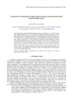
1
62nd International Astronautical Congress, Cape Town, SA. Copyright ©2011 by Surrey Satellite Technology Ltd. All rights reserved.
IAC-11-B4.6B.8
STRAND-1: USE OF A $500 SMARTPHONE AS THE CENTRAL AVIONICS OF A NANOSATELLITETE
Shaun Kenyon
Surrey Satellite Technology Ltd. (SSTL), Guildford, Surrey, United Kingdom, [email protected]
Dr Christopher Bridges
Surrey Space Centre (SSC), University of Surrey, Guildford, Surrey, United Kingdom, [email protected]
Doug Liddle, Bob Dyer, James Parsons, David Feltham, Rupert Taylor, Dale Mellor, Andrew Schofield,
Rosie Linehan, Richard Long, Juan Fernandez, Haval Kadhem, Phil Davies, Jonathan Gebbie, Nick Holt
SSTL
Peter Shaw, Lourens Visagie, Theodoros Theodorou, Dr Vaios Lappas, Dr Craig Underwood
SSC
STRaND-1 is the first in a series of Surrey Satellite Technology Ltd. (SSTL)-Surrey Space Centre (SSC)
collaborative satellites designed for the purpose of technology path finding for future commercial operations. It is the
first time Surrey has entered the CubeSat field and differs from most CubeSats in that it will fly a modern
Commercial Off The Shelf (COTS) Android smartphone as a payload, along with a suite of advanced technologies
developed by the University of Surrey, and a payload from the University of Stellenbosch in South Africa. STRaND1 is also different in that anyone (not just from the space engineering or space science community) will be eligible to
fly their “app" in space, for free. STRaND-1 is currently being manufactured and tested by volunteers in their own
free time, and will be ready for an intended launch in the first quarter of 2012.
This paper outlines the STRaND pathfinder programme philosophy which challenges some conventional space
engineering practises, and describes the impact of those changes on the satellite development lifecycle. The paper
then briefly describes the intent behind the design of STRaND-1, before presenting details on the design of the
nanosatellite, focussing of the details of the innovative new technologies. These technologies include two different
propulsion systems, an 802.11g WiFi experiment, a new VHF/UHF transceiver unit and a miniature 3-axis reaction
wheel assembly. The novel processing setup (which includes the smartphone) is discussed in some detail,
particularly the potential for outreach via the open source nature of Google's Android operating system. A stepthrough of the planned concept of operations is provided, which includes a possible rendezvous and inspection
objective, demonstrating equal or improved capability compared to SNAP-1 with a reduced total system mass.
Finally, data from the test campaign is presented and compared against other notable CubeSats known for their
advanced capabilities. Rendered images of STRaND-1 are shown in Fig. I and are discussed later in the paper.
Figure I: Rendered Images of the STRaND-1 3U Satellite
IAC-11-B4.6B.8
Page 1 of 19
62nd International Astronautical Congress, Cape Town, SA. Copyright ©2011 by Surrey Satellite Technology Ltd. All rights reserved.
I. INTRODUCTION
STRaND Programme Philosophy
The aims of the STRaND (Surrey Training,
Research and Nanosatellite Development) programme
are:
• To challenge both the current industry standard
development processes and the traditional
Surrey approach to discover new ways of
designing, manufacturing and testing space
hardware
• To demonstrate novel space technologies or the
use of existing but modern terrestrial
commercial-off-the-shelf (COTS) technologies
in space.
• To provide a rapid hands-on training
experience for less experienced engineers and
academics in designing and building new
satellite technologies.
The STRaND programme is intended to be a longterm arrangement between Surrey Satellite Technology
Ltd (SSTL) and the Surrey Space Centre (SSC), with
STRaND-1 the first of a long line of STRaND
nanosatellite missions. It builds upon a similar
programme a decade ago, which resulted in the highly
successful SNAP-1 nanosatellite mission, launched in
2000 [1].
The STRaND programme has a unique funding
arrangement with some limited support effort and all the
hardware funded by SSTL and SSC. The vast majority
of the manpower is volunteered by engineers from both
organisations in their spare time. Additionally, there is
no exchange of funds between SSTL and SSC. The
engineers are motivated to be involved in STRaND-1
for their own education and the opportunity to ‘own’
and build a mission of significance.
The funding of hardware and additional support is
provided by SSTL/SSC to help guarantee mission
success. SSTL/SSC are motivated by the education of
the engineers, the opportunity to participate in a mission
that making use of bleeding edge technology and by the
capture of the valuable lessons learned by the team
while doing such a novel mission.
CubeSat technologies, and so the two organisations
made use of the serendipitous timing. The result of the
feasibility study and requirements exercise was an
initial mission concept for a rapid, extremely low cost
technology demonstrator, including a list of payload
candidates, a component make/buy list, high level
concept of operations (CONOPS) and mass, power and
budgets.
The goals set for the inaugural STRaND mission
were graduated into three levels of priority, and covered
all aspects of the programme, including programmatic,
management and technical goals. The three levels of
programme goal priority were primary, secondary, and
tertiary, or informally the “must-haves”, “nice-tohaves”, and “if we’re lucky”. Only the primary set of
goals need to be achieved for the mission to be a
success.
A first call for volunteers went out in the summer of
2010, and an overwhelming response from staff at both
SSTL and SSC was received. This number was reduced
to a manageable level through organic means of
consultation about realistic work levels, project
priorities and personal benefit from involvement on the
mission.
By January 2011 the team had finalised the payload
selection, finalised all the make/buy decisions, made
some initial procurements, completed a first draft of the
3D design and started detailed design work on the
subsystems to be developed in-house.
At this point the first press release and academic
paper were published [2] receiving great interest from
the technology media [3] and CubeSat academic
community. The key parts making STRaND-1 and
photographed for media use is shown in Fig. II.
Mission Chronology
STRaND-1 started out as a feasibility study and
mission requirement exercise in the Mission Concepts
team at SSTL in the February of 2010. The aim of the
study was to answer the question: ‘what could Surrey do
to harness the miniaturisation revolution of consumer
electronics of the last 10 years (i.e. since SNAP-1)?’.
Simultaneously, SSC were developing advanced
IAC-11-B4.6B.8
Figure II: STRaND-1 Hardware in January 2011
Progress continued on the technical design,
culminating in a Saturday workshop in July in
replacement of a Critical Design Review.
The mission is now in MAIT phase, with some basic
functionality tests complete and regression testing
methods used as and when new modules are added to
Page 2 of 19
62nd International Astronautical Congress, Cape Town, SA. Copyright ©2011 by Surrey Satellite Technology Ltd. All rights reserved.
the system. This way of doing MAIT has been found to
be the most flexible when the order in which the units
are ready for integration and test is unpredictable.
Mission Goals
As discussed in Mission Chronology, the Mission
Goals were gradated in to three separate levels of
priority. As shown in Table I, the bar for mission
success has been set intentionally low as STRaND-1 is
primarily a training mission.
A number of the mission goals relating to gaining
engineering experience and maintaining ties between
the two organisations have already been satisfied, and in
some ways the programme can already be considered a
success.
What remains is the execution of the remainder of
the development of the STRaND-1 satellite and the
execution of the mission.
It is expected that the satellite hardware will be
ready to deliver to a launch agency before the end of
2011.
Requirement
Primary
Mission Requirement
• Gain engineering experience for
SSTL staff
• Work closely with SSC to maintain
ties with the university
• Fly something and demonstrate an
operational telemetry link
Secondary
• One or more of the payloads work
• Rapid development and build time
• Demonstrate the use of modern
COTS for space applications by
accepting an above-normal level of
technical risk
Tertiary
• Remote inspection of a rocket body
• Sustained outreach programme
• Gain heritage of STRaND
components for use in commercial
SSTL missions
Table I: STRaND-1 Mission Goals
Figure III: CAD Design of the STRaND-1 satellite
without the main structural chassis
II. TECHNICAL DESIGN OF STRAND-1
Overview
STRaND-1 is what is known as a three-unit (3U)
CubeSat, meaning that the design of the satellite follows
the guidelines of the CubeSat Standard [4]. To
investigate how much could be achieved with a 3U
design limit; CAD models were used to investigate the
volume fit of each module and associated parts. Figures
III and IV show the CAD design with and without the
main chassis.
IAC-11-B4.6B.8
Figure IV: STRaND-1 CAD image showing the nadir
panel and both deployable solar panels in their deployed
state
Configuration
STRaND-1 uses a Pumpkin 3U (Rev D) [5] solidwalled chassis with Surrey-built deployable solar panels
to provide increased power. The panels hinge along the
long edges of the satellite and can be considered
“wings” given their nominal orientation to the flight
Page 3 of 19
62nd International Astronautical Congress, Cape Town, SA. Copyright ©2011 by Surrey Satellite Technology Ltd. All rights reserved.
direction. The deployable panels have a secondary
function at the end of life, when the satellite’s
orientation is changed to increase the satellite’s ballistic
co-efficient to increase atmospheric drag and to aid in
the de-orbiting of the satellite.
The system diagram in Fig. V shows the key
subsystems and buses on STRaND-1. Given the
adoption of I2C by existing CubeSat COTS modules,
most of STRaND-1’s subsystems operate as slaves, only
responding to requests from bus masters. The primary
bus master is the GomSpace OBC [6] but the OBC itself
may operate as a slave to upload new binaries or for
fault recovery. The transceiver radio module can send a
watchdog interrupt signal using a dedicated UART to
the OBC to reset it to a slave mode where a recovery or
new binary can be uploaded, known as a bootloader
mode. To return back, the transceiver can send a reset to
master command where the standard mode of operation
is returned.
Additionally, when the mobile phone performance
and susceptibility to SEUs has been characterised to a
satisfactory level, the I2C bus shall be switched again to
make the mobile phone the bus master, and so it can act
as the OBC of the satellite.
propulsion system dominate the total mass. When one
considers that both the propulsion system and AOCS are
in fact demonstration payloads, the total payload
complement accounts for 43% of the system mass. The
structural mass is 30% of the total mass implying that
further structural mass optimisation is possible and
desirable.
System
Mass with 10% margin
AOCS
0.4
Power
0.2
Communications
0.3
Propulsion
0.5
OBDH
0.1
Environmental
0.0
Structure
1.0
Harness
0.2
Payload
0.4
Sub-system total
3.2
System margin
0.3
Dry mass
3.5
Propellant
0.4
Launch mass
3.9
Table II: Spacecraft mass budget
STRaND-1 Mass Configuration
Payload
13%
AOCS
13%
Harness
7%
Power
7%
Communications
10%
Structure
30%
Propulsion
17%
OBDH
3%
Figure VI: STRaND-1 Mass Breakdown
Figure V: STRaND-1 System Block Diagram
Mass and Power Budgets
Table II shows the spacecraft mass composition by
sub-system before a 10% system margin is applied. As
can be seen in Figure VI, the structure, AOCS and
IAC-11-B4.6B.8
Over a single orbit the spacecraft can raise 10 W
peak power and 3 W orbit average power (OAP). OAP
can be increased by operating the satellite in sunpointing mode, where the orientation of the satellite is
fixed with respect to the Sun, which increases the OAP
to 5.8W. Peak power demand could be as high as ~24
W, occurring when all systems are operated at the
maximum operating power rating. The 20 Whr batteries
would permit ~1.25 hr of continuous peak demand
operations in eclipse and ~1.40 hr with solar power
averaged over the orbit. As no program requires the
case whereby all systems are operating in this manner, a
nominal peak power demand of <10 W is expected.
Page 4 of 19
62nd International Astronautical Congress, Cape Town, SA. Copyright ©2011 by Surrey Satellite Technology Ltd. All rights reserved.
Figure VII: S/C Orientation in Nadir-pointing mode
(left) and sun-pointing mode (right)
System
Pulsed plasma thruster
AOCS controller
AOCS Sun/Nadir sensor
GPS Receiver
RF Transmitter
RF Receiver
Butane resistojet
Smartphone
High Performance Computer
Sub-system total
System margin
Total peak power
Table III: Peak power demands
components
Power, W
4.9
0.1
0.5
1.0
3.3
1.6
7.0
1.2
2.0
21.6
2.2
23.8
of various s/c
COTS Subsystems
There are numerous commercial off-the-shelf
systems on STRaND-1, these include the GomSpace
A712 OBC [6] ClydeSpace Electrical Power System
(EPS) [7] and Daughter Battery module [8], Pumpkin
CubeSat solid wall structure [5], SSTL SGR-05 GPSR
[9], and Digi-Wi9C module [10]. These units were
chosen to reduce development time of STRaND-1
where building an equivalent unit in-house would have
driven the schedule, or where the cost benefit was such
that it costs less to make the purchase than develop inhouse, even when using voluntary effort.
Onboard Computer
The system is an off-the-shelf GomSpace A712
“Nanomind” computer which includes a 40MHz ARM7
processor, 2MB RAM, 8MB Flash, I2C controller,
three-axis magnetometer and 3 reversible PWM outputs
for driving magnetorquers. The unit is in the PC104
form factor and thus forms part of the spacecraft's core
system stack.
IAC-11-B4.6B.8
During normal operations the GomSpace OBC
controls the overall operation of the spacecraft. The
intention is that experiments on the phone will
demonstrate its utility as the spacecraft's primary OBC,
at which point the GomSpace unit’s role will be kept to
a minimum: just enough to keep the spacecraft flying in
a state that will catch the Sun and allow the smartphone
camera to image the Earth and other targets, and allow
said images to be transferred to the ground. In order
that such activities can be orchestrated from the ground,
the OBC system also relays commands and telemetry
between the hardware attached to the I2C bus on the
spacecraft, and the ground, effectively making itself
transparent in this respect.
The OBC is loaded with a FreeRTOS-based minimal
operating system supported by a “newlib” C library
which, together with some functions furnished by a
GomSpace-supplied
library,
provides
enough
functionality to read the magnetometers and drive the
magnetorquers and I2C bus. It is left to the STRaND-1
developers to add tasks to this system which operate the
STRaND-1 spacecraft as required.
In order to achieve maximum reliability while
providing a suitably flexible operating environment for
the varied experiments that might be conducted on
board, the STRaND operating system (which sits on top
of FreeRTOS, newlib, and the GomSpace library) is a
very small kernel just capable enough to sequentially
(round-robin) execute modules of code loaded in
memory; two such modules are pre-loaded and provide
the means to upload new modules and to manipulate the
module execution list. Upload is completed through a
custom “Strandatoga” protocol allowing the OBC to
reverse-acknowledge reception, allowing the system to
re-request missing or corrupted fragments. With those
in place further such modules can be pre-loaded or
retrospectively actively loaded to take care of all the
requirements of the OBC.
The lowest-level requirement of the OBC is to
master the I2C bus and to provide timely access to it by
the attitude determination and control system (ADCS)
which also runs on this computer. This in fact dictates
the main operation of the OBC: all modules are
executed in a round-robin fashion up to the top of each
second, when the ADCS is allowed to run. This also
means that the ADCS has full mastery of the I2C bus
when it runs, and thus can perform its operations with
implicit reliability and timeliness. The ADCS will
operate the rest of the spacecraft using the same
telemetry and telecommands and interfaces described
below.
The system provides access from the ground to all
the physical telemetry points on the I2C bus, and allows
telecommands to be relayed to those nodes. The OBC
itself also provides soft nodes which allow the ground
station access to the operating system's, and ADCS's,
Page 5 of 19
62nd International Astronautical Congress, Cape Town, SA. Copyright ©2011 by Surrey Satellite Technology Ltd. All rights reserved.
internals, and these can be utilised as intelligent I2C
nodes which operate other items on the spacecraft with
more high-level semantics. In order to ensure that all
eventualities can (theoretically) be dealt with, the
underlying principle that has been followed in designing
the OBC's own telemetry points is that all internal
variables can be accessed and modified live. This is
accomplished by mapping nodes onto modules, and
channels to offsets into structures in which each module
keeps all of its data. Access to these data is through a
shadow application on the ground which is compiled
using exactly the same source code headers as the onboard software, so that it knows exactly how the various
variables in all the modules are packed into the
structures and relate to the telemetry and telecommand
“nodes” and “channels”.
In order to perform mission tasks the OBC will itself
execute telecommands at given times. Schedule files
(“skeds'”; lists of telecommands and requisite times) are
uploaded using the same mechanism as for uploading
modules, and then the top item on the sked will be
inspected frequently and a telecommand issued if the
time is right.
The highest-level task the on-board computer must
carry out is the marshalling of images from the
smartphone, via the high performance computer (HPC),
to the transmitter so that they can be received at the
ground.
The previously-mentioned Strandatoga
protocol is available for ground-based negative
acknowledgement (allowing the ground to indicate parts
of images which must be re-transmitted due to drop-out)
if required, though probably in the case of images this
facility would not be used with the occasional drop-out
of some image pixels being tolerated by the operators.
Electrical Power System
The STRaND-1 power system is operated using the
ClydeSpace electrical power system (EPS) and 20 Whr
daughter battery board. Using these two parts, the
satellite can regulate power flow from the solar panels,
to the battery, and to various payloads. There are two 30
x 10 cm solar panels, a smaller tertiary dorsal panel and
a smaller panel facing Earth. The largest panels will
provide 6.9 V at 0.86 A with 6 triple-junction 4cm x
7cm 27.5% efficiency solar cells, reduced to 26.5% due
loss of area, diode leakage, and covering. Both EPS and
battery modules are addressable I2C nodes which can
send status bytes on module temperatures and currents.
Other Subsystems
One of the best examples of where the ‘T’ in
STRaND can be seen is in the communication system.
Early on in the mission it was decided that the whole
radio chain from antenna to analogue radio to digital
section to bus would be developed in-house. Given the
historical strength of SSTL in space-worthy radio
IAC-11-B4.6B.8
communication systems it was felt this provided the best
learning opportunities, and opportunities to tap existing
expertise in the company. Therefore a team of engineers
with limited RF design experience designed the RF
section of the STRaND-1 satellite under supervision
from some of the most experienced engineers in the
company.
Antenna Assembly
STRaND has two monopole antennas; one for the
2m-band uplink and one for the 70cm-band downlink.
The requirements for the antennas were to:
•
•
•
•
•
Be lightweight
Be deployable
Have a failsafe to ensure the antennas get
deployed in case of deployment electronic
failure
Fit the limited volume available, and
Have a sufficient gain for the link budget
The antennas are based on the standard UHF/VHF
whip antennas used by SSTL on their early commercial
satellites, and are influenced by the Delphi C3 antenna
deployment mechanism. The design is different from
the Delphi C3 solution in that the box geometry is
different; antennas are mounted to deploy out of the side
of the spacecraft instead of the top, which saves volume
to allow more modules in the CubeSat stack. The design
also differs in the removal of the electronics which have
been moved to a separate electronics board. The
approach not only simplifies the electronic design but
also simplifies the physical design to allow easier
manufacturing with fewer components.
The Modular Antenna Box (MAB) comprises of the
box itself which is a plastic unit (as shown in Figure
VIII) which is mounted to a standard PC104 PCB. The
PCB also contains the analogue section of the RF
transceiver creating shorter connections between the
antennas and the circuit. Another key component is the
antenna which is made out of an old, used tape measure
(kindly donated by a STRaND volunteer) cut to the
correct length and fitted inside the MAB. The final
component is the release mechanism which is a resistor
and a length of nylon wire. The nylon wire is designed
to hold the lid of the MAB down during launch. The
wire is tied to the lid and then wrapped around a resistor
and tied off to an anchor point. On launch the RF
transceiver unit will pulse a current through the resistor
which should melt the nylon wire releasing the antenna.
If the nylon wire does not melt it will outgas enough to
be structurally weakened and snap, thus deploying the
antenna.
Page 6 of 19
62nd International Astronautical Congress, Cape Town, SA. Copyright ©2011 by Surrey Satellite Technology Ltd. All rights reserved.
Figure VIII: Modular Antenna Box (MAB)
Figure IX: Integrated Antenna Unit including both the
VHF and UHF MABs
limits. The component height limits forced the design
decision to only place the smallest components on the
underside of the board (i.e. surface mounted resistors
and capacitors). This general strategy is validated by
looking at the design of other well-known COTS
CubeSat units such as the ISIS RF Transceiver unit
family and the ClydeSpace EPS unit which also place
their smallest components on the underside.
The PCB has four layers – Top, Ground, Power and
Bottom. All signal routing and component placement is
on the top and bottom layers, the majority of the
components being on the top layer. Although in normal
PCB design there is a different layer for each power
plane and additional layers for signalling, this was not
possible for this design due to height and cost
constraints.
Subsequent design changes meant that the analogue
section of the RF design was separated from the digital
section of the design, and merged with the antenna
control board. Not only did this design change help ease
the transmission length issues, it allowed more room on
the now purely Digital RF board for the routing, and
also makes the solution modular and upgradable.
The modular concept allows the analogue up and
down mixing design to be changed without any impacts
to the digital design (the interface being the I/F lines),
significantly simplifying future upgrades for S-Band
capability and robust cross-strapping redundancy.
Radio Transceiver
The RF transceiver provides the following key
functions:
• Activates the antenna deployment mechanism
• Receives and decodes data from the ground
• Encodes and transmits data to the ground
• Transmits a beacon
• Transmits and receives data to/from the OBC
via the spacecraft’s I2C bus
• Includes the ability to reconfigure the OBC via
a dedicated UART interface
Frequency coordination with IARU has been
completed, and IARU has recommended the frequency
allocation of 437.575 MHz for downlink, and 145.860
MHz for uplink. The next step to be taken imminently is
to notify the relevant national authority, who is then
expected to notify the ITU.
Originally, the aim was to have both the analogue and
digital sections of the design on a single printed circuit
board for volumetric efficiency. Although manageable
and indeed proven possible by the existing COTS
CubeSat RF systems, this was a challenge for an ECAD
learning activity, given the size of board allowed by the
PC104 standard, including the large amount of real
estate taken by the header and the component height
IAC-11-B4.6B.8
Figure X: RF Transceiver Block Diagram
The RF subsystem as a whole is centred on
inexpensive and readily available single chip UHF
transceivers. Two of these devices are used; one for
transmit and one for receive.
The transceivers are controlled by the PIC24
microcontroller. Since the downlink frequency is the
same as that outputted from the transmitting IC, the RF
output from the transceiver is passed directly to a
GaAs High Power Amplifier (HPA) and then to the
transmit antenna. The HPA will provide nominal RF
output power of 1 W, which can be increased to 1.5 W
if required. When operating in Beacon / CW mode, the
RF output power will be reduced to 0.25 W. On the
uplink, the UHF input from the receive antenna is first
Page 7 of 19
62nd International Astronautical Congress, Cape Town, SA. Copyright ©2011 by Surrey Satellite Technology Ltd. All rights reserved.
amplified by a low noise MMIC amplifier and then upconverted to UHF frequency before being passed to the
receiving IC.
redundancy exists, and this is the accepted approach for
this mission. The ∆V capability would also be reduced
if redundancy were required – tank volume would be
reduced to allow space for the redundant components.
Figure XII: STRaND-1 Propulsion System Schematic
Figure XI: Breadboard components for analogue
front end of STRaND-1 Radio Transceiver
The digital section is centred on an inexpensive and
readily available PIC24 microprocessor. The transceiver
ICs are configured on power on by the microprocessor
via an SPI interface. Data is transmitted to/from the
microprocessor via a separate serial line. The
microprocessor performs AX.25 decoding/encoding of
received and transmitted data respectively. The primary
method of communication with the rest of the spacecraft
is via the I2C bus; telecommands, telemetry and data are
all sent via this bus. It is also possible for the ground
station to communicate directly with the RF transceiver
via a limited command set and a dedicated serial link to
the OBC is also provided. These combine to allow the
OBC to be reconfigured in the event of a fault, or if a
software update is required.
Butane Propulsion System
The propulsion module on STRaND is split into two
parts; the SSTL butane resistojet (based on the heritage
SSTL resistojet) and the SSC Pulsed Plasma Thruster
(PPT).
The STRaND-1 CubeSat is baselined to have a
warm gas butane propulsion system on board to enable
orbital manoeuvres. The system builds on the extensive
SSTL heritage with the design and operation of butane
propulsion systems, while testing out new processes and
hardware to reduce the system size and cost. These two
points are critical to enable the system to be viable for a
CubeSat. The propulsion system must fit in a space
smaller than 75x75x21mm, and had to be completed on
a stringent budget. Typical space-rated components
were ruled out for these reasons.
The system is designed to provide 2ms-1 ∆V to the
STRaND-1 CubeSat. A basic schematic for the system
can be seen in Figure XII. It should be noted that no
IAC-11-B4.6B.8
The propulsion system will be loaded with
propellant through a fill/drain valve. For this, a Lee
chek valve is utilised with a special ground half
coupling manufactured to allow the valve to be opened
mechanically. The valve is incredibly small and
affordable making it ideal for this application.
The propellant is stored in a bespoke tank,
constructed from two aluminium billets and welded
together. Butane is a liquefied gas so stores under its
own vapour pressure (~2.1 bar at 20oC). The tank is
designed to survive a burst test of >4 times maximum
expected operating pressure (MEOP) to prove it is safe
for launch. MEOP has been defined as 4 bar, and so the
burst pressure will be in excess of 16 bars. A
temperature sensor is attached to the tank – this will
allow the pressure in the tank to be estimated.
A Lee solenoid valve is employed as a flow control
valve in the system. The small size again made it ideal.
All internal materials are compatible with the propellant
and test gases.
The resistojet itself is manufactured by SSTL. It is a
simple design consisting of a resistive wire wound
round a mandrel. The gas is forced to spiral down the
resistojet to increase the travel path and thus the heat
transfer. The resistojet acts as a vaporiser to ensure no
liquid propellant is expelled, as well as increasing the
specific impulse of the system.
A CAD image of the system can be viewed in Figure
XIII.
Page 8 of 19
62nd International Astronautical Congress, Cape Town, SA. Copyright ©2011 by Surrey Satellite Technology Ltd. All rights reserved.
Figure XIII: SSTL-heritage resistojet embedded in a
custom propellant tank
Pulsed Plasma Thrusters (PPTs)
The PPT is a form of electric propulsion (EP)
thruster that operates in a non steady (i.e. pulsed) nature.
Energy is drawn from the satellite bus and stored in the
thrusters’ capacitors (two parallel CR09 ceramic chip
capacitors per thruster). The electrodes of each capacitor
act as the propellant source. When the electrodes are
shorted, large currents form that pass through the
electrodes eroding them. In the case of STRaND the
shorting mechanism is a contact trigger actuated by an
external initiation device. This contrasts to other PPTs
where initiation is nominally by a sparkplug.
The material released in this erosion forms plasma.
A Lorentz-force (JxB) is produced from the interaction
between the high flowing current and the subsequent
induced magnetic field. This µN force propels the
plasma out of the nozzle to generate thrust. Once the
PPT capacitor discharges completely, the plasma is
extinguished and the process begins anew, leading to a
discrete set of impulse packets that can be used for
manoeuvring.
They are welded to tin coated copper electrodes that are
‘blade like’ in nature to provide reduced internal
inductance and to promote electrode erosion. The
capacitor and electrodes are housed within ULTEM™
cases and the thruster is initiated by a spring loaded
contact trigger mechanism using a piezo- electric motor.
The capacitors are charged to 800V, supplied by the
PPU. The PPU uses a set of six parallel high voltage
DC-DC convertors taking the 5V CubeSat bus voltage
to 800V. Single chip power filters are used to minimise
ripple effects on the power lines and a set of diodes and
high voltage resistors are used to ensure correct thruster
firing and to limit spot welding. The predicted
performance of the PPT module from models generated
by the University of Surrey suggest that the specific
impulse of the technology should be around 320s with a
total ∆V of around 2.7ms-1. However with a slight
simple modification to the electrode design in future
versions of the design this should increase to around
76.3ms-1.
Additional testing performed using the University of
Stuttgart’s impulse balance apparatus has revealed that
the PPT’s true specific impulse is 1340 seconds,
requiring 1.5W of power and producing a thrust of
0.9µN (averaging the impulse bits that fire at a rate of
one every four seconds)
If STRaND-1 is successful this will be the first EP
thruster to operate successfully on a CubeSat platform.
Attitude Determination System
The CubeSense module is an integrated sun and
nadir sensor for CubeSat attitude sensing. It is also the
subject of another dedicated IAC paper [11]. It makes
use of two CMOS cameras – one dedicated to sun
sensing and another for horizon detection – mounted on
a PC104-sized PCB.
The Sun sensor has a neutral density filter included
in the optics to ensure that only the sun will be visible in
the image. Both cameras have wide field-of-view optics
(180 degrees) for increased operating range. The
primary outputs of the sensor are the measured Sun
vector and nadir vector in the sensor’s coordinate frame.
The measured vectors are output as azimuth/elevation
angles relative to the camera bore-sight. The CubeSense
module can also be used as a camera and is shown in
Fig. XV.
Figure XIV: Pulsed Plasma Thruster Bank Flight
Modules
The STRaND pulsed plasma propulsion system is
made from three PC104 Boards. Two boards house four
PPTs each and the third acts as the pulsed power unit
(PPU). The PPTs are two CR09 chip capacitors placed
in parallel to provide a total capacitance of 0.76 µF.
IAC-11-B4.6B.8
Page 9 of 19
62nd International Astronautical Congress, Cape Town, SA. Copyright ©2011 by Surrey Satellite Technology Ltd. All rights reserved.
(i.e. limiting the current to ~625 mA at 5V). There are
172 turns per layer and 7 layers giving ~1200 turns and
a total diameter of ~11mm. The expected magnetic
moment is between ±0.4 and ±0.8 Am2. The torquers
are controlled by a NanoMind A712B computer board,
which provides three 5V pulse-width modulated (PWM)
bi-directional H-bridge drivers, which can each source
up to 3A, with a total current capability also of 3A. The
combined current draw of the three magnetorquers is
1ess than 2A.
Attitude Control Methodology
Figure XV: Univ. of Stellenbosch-developed CubeSense
Attitude Determination System
Attitude Control Actuators
Three reaction wheels will be flown on STRaND-1
in an orthogonal configuration. These will provide
three-axis control, augmented by the magnetorquers for
desaturation but also used as momentum wheels for the
commissioning phase. Due to volume constraints, two
differently sized wheels are used. Fortunately, due to
the non symmetrical nature of STRaND-1 both wheel
sizes have been designed to meet the same performance.
The reaction wheels are capable of slew rate of 90⁰ in
60s at a maximum wheel speed of 5000rpm. Each
wheel is an independent I2C node consisting of a
microcontroller that handles the communication, motor
commutation and control loop. The brushless DC motor
is driven by three half H-bridges made from discrete
components. A PID control loop is used with a
maximum error of ±5rpm over the full speed range. The
nano-wheel and assembly are shown in Fig. XVI.
Figure XVI: STRaND-1 Nano-reaction wheel (left), and
RW assembled unit (right)
External torque is provided by three orthogonally
mounted magnetorquers, each comprising a 6.35mm
diameter, 74mm long rod of Supra50 Iron-Nickel alloy,
with ~32m of 30 SWG (0.315mm diameter) enamelled
copper wire, giving a resistance of approximately 8 ohm
IAC-11-B4.6B.8
The STRaND-1 satellite will employ various control
modes throughout its operation. The first detumbling
control mode will engage automatically after being
released from the launch vehicle. Initially the satellite
will be tumbling at an unknown rate. The purpose of the
detumbling controller is to limit the angular rotation of
the satellite ultimately resulting in a rotation only about
the Y-axis, where the rotation rate is controlled to a
reference value (typically 2 deg/s). Additionally, the
satellite Y-axis will be aligned with the orbit antinormal. This is achieved with combined B-dot [12] and
Y-Thomson [13] control laws.
The controller requires knowledge about the current
attitude rate. A Kalman filter rate estimator [14] that
makes use of successive magnetometer measurements
will provide this information. The estimator does not
require any orbit information and is robust against
modelling errors.
Another advantage of this control mode is that it
requires attitude sensing information from only the 3axis magnetometer, and control is achieved using only
the torquer rods. The mode can thus be implemented
using only the NanoMind processor and its peripherals.
After the solar panels have deployed, the control
mode will change to a sun-seeking precession controller
[15]. The STRaND-1 satellite has its main solar panels
facing in the +Y body direction. In the previous
detumbling control the satellite Y-axis (and thus also the
solar panel normal vector) will be angled away from the
sun direction. The sun-seeking precession controller
will make use of measurements from the sun sensor of
the CubeSense module to precess the solar panel normal
vector to the sun vector. All the while the satellite will
still be tumbling about its Y-axis and during eclipse the
controller will fall back to the Y-Thomson mode to
control the spin rate to 2 deg/s.
The remaining control modes will make use of the
reaction wheels. The first mode will use the Y-axis
aligned reaction wheel as a momentum wheel to absorb
the angular momentum of the spinning satellite and
bring it to an approximate nadir pointing attitude. It will
also continue to align the spacecraft body Y-axis with
the sun vector for optimal power generation, and damp
Page 10 of 19
62nd International Astronautical Congress, Cape Town, SA. Copyright ©2011 by Surrey Satellite Technology Ltd. All rights reserved.
the nutation rates about the body X- and Z-axes. In
eclipse the satellite will remain nadir pointing.
From the Y-momentum mode, the 3-axis controller
can be activated. In 3-axis control mode all three
reaction wheels will be used to control the attitude to
some reference attitude and the torquer rods will be
used to manage the reaction wheel momentum
(momentum dumping). During eclipse the reference
attitude will be the nominal attitude (zero roll, pitch and
yaw) and in sunlit parts of the orbit the reference
attitude will be calculated so that the body Y-axis points
toward the sun. Additional commands from the ground
can be sent to change the reference attitude temporarily
so that specific pointing manoeuvres can be performed.
The Y-momentum and 3-axis control modes requires
both attitude and attitude rate information. This will be
provided by a full-state EKF (extended Kalman filter)
[14]. The EKF makes use of sensor measurements from
all the available sensors (magnetometer, sun and nadir
sensors) and corresponding modelled vectors for each of
these to estimate the current attitude quaternion and also
the orbit referenced angular rates. The modelled vectors
are obtained from a sun orbit model and IGRF magnetic
field model, running on the OBC. The modelled vectors
also depend on the current satellite position. This will be
provided by an SGP4 orbit propagator running on the
OBC, initialized with a two-line element set that will be
uploaded from ground once this becomes available.
-Z
•
•
•
•
Basic Control (on/off) using GPIO and USB
ports. This is achieved by an application on the
smartphone and a switch between the
smartphone’s battery and the smartphone itself.
Wireless Control (on/off) using WiFi interface.
If the USB fails, then WiFi access is possible
using a virtual terminal and mounting of the
SD-card in Linux.
Upload/Download code using any port or
interface. This may include operating system,
user, data, or application installations to
various partition areas on the smartphone.
Telemetry Handling. Converting data and
metadata (discussed later) to I2C formats. Both
the
Digi-Wi9C
and
Nexus-One
are
experimental payload computers and use
separate addresses, handled using a separate
PIC microcontroller.
The HPC board monitors the smartphone using USB
as the primary link and the WiFi as the secondary link,
with the capability to operate at the same time for
limited experimental periods. An additional VGA
camera is mounted close to the smartphone and can
provide visual access should both USB and WiFi links
fail as shown below in Figure XIX.
HPC board
VGA Camera
Deep Space
Camera view of smartphone
screen
Mobile Phone Screen
Orbit Normal
Figure XVIII: Diagram showing how the internal
configuration showing the VGA camera and the mobile
phone.
+Y
Flight Vector
+X
Nadir
+Z
Figure XVII: STRaND-1 body-fixed axis definition
High Performance Computer
The high performance computer (HPC) is based on a
modified Digi-Wi9C [10]. The primary uses are to
provide I2C interfaces and communications between the
smartphone and spacecraft bus, as well as additional
services for monitoring the Nexus-One. These services
include:
IAC-11-B4.6B.8
Figure XIX: Nexus-One Monitoring Camera
Page 11 of 19
62nd International Astronautical Congress, Cape Town, SA. Copyright ©2011 by Surrey Satellite Technology Ltd. All rights reserved.
There are numerous applications currently under
development or test. These include a house-keeping
telemetry app, which periodically pings the phone to
ensure status, and smartphone charge/discharge drivers.
Mobile Phone System
The smart phone was chosen after an extensive trade
study as part of the initial feasibility study. The
smartphone chosen was the Google Nexus-One [16] and
has been integrated into the STRaND-1 CubeSat with
the initial aim of providing the main imaging payload
but with the ultimate intention to assess the opportunity
to assess the smartphone’s capabilities to perform the
primary on-board computer role. With the limited
project timescale, the focus is on finding 'fit-forpurpose' rather than technically superior solutions. Inorbit updates will be used where possible to improve the
software capabilities.
The Nexus-One will connect to satellite subsystems
over USB using the HPC which will allow a Linux
platform to operate a reduced Android Debug Bridge
(ADB). This ADB will facilitate the control over
flashing boot kernels, restarting the phone and
installation of new applications (or ‘apps’). The Android
development Kit (ADK) is also under investigation as a
more advanced interface library. The Nexus-One’s flash
memory acts as a shared space between the HPC and
Nexus-One for telemetry, telecommand, payload
acquisition, processing schedules, and payload imagery
managed by both systems. Each of these 'components'
will consist of a metadata file and a data file. However,
to address possible SD Card corruption dues to single
event effects (SEEs), etc., both the metadata and data
files will be triplicated. As any usage of the 'data'
component will need to manage read/writing with these
three files, the HPC and phone will operate an
abstracted layer to control these interactions. Both the
phone and the HPC will be responsible for their
management of these metadata and main data files and
will use the metadata header and data table to ensure
seamless synchronised shared usage of the data; e.g.
marking up a block when the device is writing to it, etc.
Uploads of new software (kernels, apps, etc.) will be
managed by file control messages with the files being
directly stored on the SD Card rather than through this
metadata/data mechanism as usage and management of
these will be through other tools such as Fastboot and
ADB on the HPC. The phone itself will autostart the
prime schedule and status management tool that is
responsible for managing the execution of phone apps,
telecommand handling, output of critical telemetry, and
the interaction with the component metadata/data files
on the SD Card.
The Linux kernel is a reduced version of 2.6.32 with
GPS functionality removed amongst other minor
changes to produce a smaller memory footprint. The
IAC-11-B4.6B.8
Xconfig tool supports the production of bespoke kernels
but is a challenging and unintuitive tool to create a
compatible kernel on both the HPC and Nexus-One. For
the payload, there are multiple resolutions supported by
imaging schedule files and the system will default to the
maximum image size of 2592 x 1944 pixels with image
data saved as lossy-JPEG with tailored compression.
Development of applications and software is
currently ongoing, with the aim to support STRaND
Facebook Apps [17]. The Linux kernel and Android
kernel are both fully compiled and tested as shown in
Figure XX. The smartphone itself is also under rigorous
testing as also shown in Figure XX in the holding tray.
Figure XX: Nexus-One Software Information and
Nexus-One Payload in STRaND-1 payload-tray
The phone has already been vacuum tested. The
phone was placed in to a vacuum bell jar and pumped
town to 1 millibar (+/- 0.5mbar), and no adverse effects
were observed. The phone has also undergone
preliminary thermal stress tests, where the phone was
found to operate between +65°C and -5°C, and to cease
operation and power down outside of this temperature
range.
The thermal tests have highlighted the sensitivity of
the phone to cold (i.e. automatic power-off), and so
more focus has been given to keeping the phone warm
on the satellite through charging regimes and processor
intensive routines.
Page 12 of 19
62nd International Astronautical Congress, Cape Town, SA. Copyright ©2011 by Surrey Satellite Technology Ltd. All rights reserved.
Figure XXI: Nexus One under vacuum test at SSTL
premises
A radiation test has been conducted on the phone,
however the results were inconclusive due to an error in
the test setup. The phone was subjected to a dose in
excess of 21kRads, and would not power on after the
test. A further radiation test of 3 units will be conducted
in the near future with a more robust test setup,
recording multiple telemetry points inside the phone.
III. CONCEPT OF OPERATIONS
safe in tumbling mode before deployment of solar
panels.
The GPS receiver will acquire the spacecraft
position whilst built-in Magnetometers on the OBC will
be used to measure both direction and magnitude of the
Earth's field on 3-axis. The comparison of these
observations with a vector model of magnetic field will
determine the magnitude and polarity for the
magnetorquer's firings to control the spacecraft's
orientation. The initial tumbling rates expected are
likely to be less than the 30deg/sec experienced by
SNAP-1, as the CubeSat deployer uses guide rails.
Once the spacecraft has reached a safe state, a full
system check is required. The communications system
allows a direct link to the OBC flash memory to enable
loading or reloading of OBC software without OBC
involvement, but ultimately the OBC is required to log
essential telemetry: magnetometer vectors, temperature
sensors, solar array voltage / current, battery voltage.
The minimum refresh rate is TBC and will define the
minimum downlink data rate required.
A higher sampling rate is expected during initial
stages but as the mission continues and increases
confidence on each subsystem’s operation, then the
sampling rates of magnetorquers can change to one or
two samples per orbit.
LEOP
Technical Experiments
Objective: Accelerated Commissioning
Estimated duration: 2 days as a goal, 1 week planned
Operation mode: Manual
The extreme capability of the mobile phone
electronics suite allows for a number of interesting
experiments that make use of the advanced COTS
technologies.
Intra-satellite link
This stage requires intensive use of the OBC and AOCS
and manual control from the SSC ground station and
other ground stations. It is estimated that approximately
5 to 10 min of communications with the ground stations
will be available on each pass. This time shall be used
efficiently; a full system health check will be required
as start. Subsequent overpasses should allow
progressive commissioning and a basic set of
diagnostics for analysis without too much
communications overhead. After separation with the
rocket launcher, STRaND is required to:
1)
2)
3)
Autonomously acquire its attitude
Promptly manoeuvre to reach a stable
pointing.
Deployment of solar panels
This will ensure a thermally and power-safe initial
state to continue with the mission. In a worst-case
scenario the uncontrolled tumble of the spacecraft can
only guarantee a maximum of 3 hrs of battery power
before battery degradation occurs, and 10 hrs before the
battery is 100% depleted. This corresponds to 2 orbits
and 6 orbits respectively. The satellite will be thermally
IAC-11-B4.6B.8
The nominal data link between the phone payload
and the platform is a USB cable. One experiment to be
conducted early on in the mission is to deactivate the
USB link and operate the mobile phone using the WiFi
link to the HPC only, perhaps demonstrating a
distributed processing task at the same time.
Demonstrating the use of a COTS wireless link is a
proof of concept for physically and electronically
distributed space systems acting as a single logical unit.
Touchscreen-based random number generator
The capacitive touchscreen of the mobile phone is
the focus of this experiment. It is hoped that SEEs will
manifest themselves as detectable events using the
Android-provided touchscreen API. Depending on the
location of the detected effect, a number is generated
and logged. The number generation log is then
downlinked and analysed for true randomness.
WiFi downlink
Using an existing SSTL-owned S-Band dish, this
experiment would aim to receive data transmitted from
the mobile phone IEEE 802.11g antenna on the ground.
Page 13 of 19
62nd International Astronautical Congress, Cape Town, SA. Copyright ©2011 by Surrey Satellite Technology Ltd. All rights reserved.
This experiment is currently undergoing feasibility
analysis, looking at link budgets, Doppler effects, and
any gain-increasing design changes such as the
introduction of a slot antenna. If such a technique if
feasible and can be demonstrated as viable, it would
dramatically increase the volume of data that can be
downlinked from STRaND-1.
Phone control of satellite
This experiment is a key goal of the mission, and
demonstrating that an Android mobile phone is capable
of operating a satellite has potential to revolutionise the
nanosatellite (and particularly the CubeSat) field. The
experiment will be graduated in that first it will merely
mimic the scheduling and control functionality of the
nominal OBC. Then, greater functionality (such as
AOCS control) will be migrated to the phone unit,
followed by a brief period running only on phoneresident sensors such as the camera, magnetometer and
accelerometers. If the latter can be achieved with some
reliability demonstrated by the phone then the result will
provide strong evidence that nanosatellites and
CubeSats in particular can miniaturise their systems
even further and increase their capability further still
whilst keeping the low cost advantage.
CCSDS SM&C
In partnership with Logica’s Space division,
STRaND-1 will demonstrate the use of the CCSDS
SM&C protocol in conjunction with the open source
Hummingbird [18] mission control system.
Pulsed Plasma Thrusters
As discussed in previous sections, the PPT bank is a
novel and highly efficient electric propulsion system.
Long term use of the thrusters on STRaND-1 will allow
for in-orbit characterisations to be made and compared
against current theoretical models and vacuum tests
conducted at the university of Stuttgart, whilst also
making observations about any adverse effects on the
rest of the satellite system (e.g. power ripples, transients
etc.).
If demonstrated to be a reliable propulsion system
the technology has potential to be the propulsion system
of choice for CubeSats due to its low power draw and
solid propellant – thus avoiding the pressure limits in
the CubeSat standards.
Outreach Activities
The combination of mobile phone technology and
space technology has already been shown to spark the
interest of the greater public and mainstream media.
Outreach seen as a core duty of the STRaND
programme, and is seen as a useful tool in inspiring
future engineers to join the industry.
App Competition
IAC-11-B4.6B.8
In the summer of 2011, SSTL and SSC launched the
first SpaceApp competition [17]. Members of the UK
public were invited to submit ideas on Facebook for
Apps that could be run on the mobile phone once in
orbit. Submitters were expected to write the app
themselves and deliver them to the STRaND-1 project
by the end of 2011. Conditions of the competition
included that the applicant must be a UK resident and
the app must be written as an open source project to be
uploaded on to s-android [19].
Four winners were selected from the entries,
including app ideas in
• telemetry trend analysis
• plasma physics, and
• outreach – including
o an experiment testing the assertion that
“in space, no one can hear you
scream”, and
o an outreach app described as
“Postcards from Space”.
Artificial Intelligence Chatbot
The combination of the very capable processor along
with the inherent Java support provided by the Android
platform, and the history of the Amateur Satellite
community using satellites to communicate, has resulted
in the concept to run an Artificial Intelligence “Chatbot”
– or more specifically an “Alicebot” [20] on the mobile
phone. Alicebots are AI routines specifically designed
for communicating with humans in an instantmessaging environment. The aim of this experiment is
to allow amateur radio operators all over the world to
interact directly with the satellite, and also allow nontechnical people the chance to interact with the satellite
in a meaningful way, for example in school sessions.
IV. TEST CAMPAIGN
Test Philosophy
The test philosophy is similar to the development
philosophy in that a subset of the normal SSTL test
approach is taken, with great emphasis on using system
end-to-end tests. Indeed, all new subsystems will be
only be vibration tested or thermally tested for the first
time during the system-level vibration and thermal tests.
For STRaND-1, SSTL and SSC maintains a flexible
approach to the sequence of AIT in an attempt to make
the best use of any available hardware and facilities at
any given time. This is to ensure that the maximum
progress is made irrespective of the order in which the
flight units become available for AIT. The distributed
TTC system used on Strand accommodates this
approach.
Test Plan
The modular nature of STRaND-1 allows initial
electrical integration to take place in any order provided
Page 14 of 19
62nd International Astronautical Congress, Cape Town, SA. Copyright ©2011 by Surrey Satellite Technology Ltd. All rights reserved.
core systems (e.g. power subsystem, harness) are
available.
As unit interfaces are not available once the
spacecraft is integrated, all data is obtained via the
following CubeSat system connections and umbilicals:
• Data umbilical (primary and secondary TTC
bus)
• RF Uplink
• RF Downlink
• Power from Solar simulator
• Safe / Arm connection (allows remote
activation of the spacecraft)
Spacecraft configurations, voltages and temperatures
are obtained via the spacecraft telemetry subsystem.
The Electrical Ground Support Equipment (EGSE)
hardware and software will be based on the ground
station design; this reduces compatibility issues to a
minimum and allows verification and test of the TTC
database and software.
Platform Pre-integration
All units and subsystems arriving in the AIT clean
room for integration into the STRaND-1 platform are to
be bench and performance tested.
All modules and subsystems will have completed
and passed a ‘Module Readiness Review’ prior to
integration.
All modules shall be visually inspected before
integration. Special attention is given to connectors to
check for contamination and damaged pins. The flight
harness is inspected and checked against the harness
manufacturing instructions and will be electrically
tested.
Platform Soft and Hard Stack
Initial integration of the platform subsystems is in a
soft stack configuration. The aim of the soft stack is to
perform an initial check on each of the individually
tested modules to verify that each one fits and functions
with the harness
Initial soft stack provides an early opportunity to test
interfaces between the platform and the payloads using
available breadboards and/or EM models.
Full soft stack requires stacking and bolting the
platform together using all flight modules and parts. It
uses flight fasteners, but the fasteners are not
necessarily torqued and adhesives are not used. A full
soft stack spacecraft can be handled safely for thermal
cycling etc, but can also be taken apart easily if any
rework is required.
‘Hard stack’ assembles the whole platform into its
flight configuration. The platform fixings will be at the
correct torque levels; staking glue or RTV will be
applied to all nuts and bolts. The flight harness will be
IAC-11-B4.6B.8
attached to support locations; all connector fixings will
be torqued and staked.
Following hard stack integration, a series of
functional tests on the platform are repeated to confirm
that all data and power interfaces are mated correctly.
Vibration Testing
A comparison between the GSFC-7000 standard
[21] random vibration spectrum that is commonly used
for CubeSats and the in-house SSTL Spectrum C
random vibration spectrum will be conducted, and
STRaND-1 will be tested as a fully integrated system to
the worst spectrum at SSTL’s facilities.
Thermal Testing
The fully integrated system will be tested in a
thermal vacuum chamber on SSC premises. The fully
integrated system will be subjected to the normal SSTL
thermal cycle. A schedule decision will be taken before
testing whether to conduct a 7-day burn-in test as well.
EMC Testing
Before the integration of the whole system, units
with EMC considerations such as the RF transceiver and
the pulse plasma thrusters will have some basic EMC
characterisation tests, then the fully integrated satellite
system will be placed in an anechoic chamber either at
SSC or SSTL premises and the EMC environments
around the satellite measured.
TTC End-to-End Tests
System tests will use hardwired connections to the
Spacecraft TTC transmitters and the data umbilical will
be connected; a wireless connection will be made from
the EGSE to the Core Spacecraft Transmitted
A wireless TTC end-to-end test is performed using
the ground station antenna. Commanding the Spacecraft
through the receiver is confirmed, and then telemetry
reception from the transmitter is confirmed. OBC code
upload tests are performed through all receiver and
transmitter combinations.
Flight Readiness Review
The FRR is the final review of the Spacecraft
integration and test campaign. This review will:
• Confirm that all the tests have been
completed as per the test plans
• Confirm all the results have been reviewed
and accepted
• Confirm that all anomalies have been
resolved
• Confirm that the required shipping and
export documentation and clearances are in
place
Page 15 of 19
62nd International Astronautical Congress, Cape Town, SA. Copyright ©2011 by Surrey Satellite Technology Ltd. All rights reserved.
The FRR will be at a much reduced scope compared
to a commercial SSTL mission.
Delivery to Launch Agency
The spacecraft will be placed in its transit case and
packed together with associated MGSE and EGSE.
V. CONCLUSION
which the satellites were developed should be noted,
however. STRaND-1 uses some COTS technologies
that were not available when the other satellites were in
development, and so the table should be regarded as a
reflection on the global trend in CubeSat capabilities.
Satellite Delfi C3
Delfi
N3XT
Cute
STRaND1.7 CanX-2
1
APDII
Virtues of the Technical solution
STRaND-1 is a testament to the enthusiasm of space
engineers in Surrey, in that they are willing to spend
their own time developing a nanosatellite of
significance.
This paper has described in some detail the technical
novelties to be demonstrated by the mission, and the
fact that all the satellite hardware has been developed
for less than $100,000 shows that the innovation in lowcost space technology continues unabated at SSTL and
SSC.
By harnessing the fruits of the intense research and
development of the mobile phone industry, the STRaND
programme intends to trace Moore’s law much more
closely than other satellite development programmes.
An interesting aside statistic is that the Google Nexus
One in terms of processing power is approximately 30
MFLOPS, or roughly equivalent to the power of a Cray
CDC7600 [22], the premier supercomputer of the early
1970s.
By maintaining the close ties with the University of
Surrey with the STRaND programme, SSTL benefits
from the continuous pioneering and advanced
technological research projects at the Space Centre, and
the University benefits from regular opportunities for
practical demonstrations of new technologies.
The multiple roles that can be performed by the
mobile phone (OBC, 5V power supply via the USB,
wireless communication, mass data storage, imaging,
magnetometer-based attitude determination etc.) has
allowed for a certain amount of flexibility in the mission
CONOPs planning and experimental scope creep.
Ultimately, the capability of the original system had
enough margin “built-in” to cope with the inevitable
mission creep that occurs in many missions. The
difference with the STRaND-1 mission however is that
the margin has meant that although the scope of the
mission and the number of planned experiments has
increased since the initial design, there has been
minimal additional work required to meet the new
requirements.
Comparison to other similar CubeSat missions
As can be seen from table IV, the performance and
capabilities of STRaND-1 are ambitious when
compared against other 3U CubeSats well known in the
community. Significant differences in the timeframe in
IAC-11-B4.6B.8
3-Axis
stabilised
Yes
Yes
(Mag)
Yes
Yes
Processor
RISC
Type
RISC
ARM
ARM
ARM
Clock 7.4
Speed MHz
7.4
MHz
400
MHz
15
MHz
1000
MHz
Yes
No
No
No
Yes
Prop
Systems
0
1
0
1
2
Camera
No
No
Yes
No
Yes
Wireless
experiment
No
Highest
VHF/ VHF/
VHF/
S-Band S-Band
Comms
UHF
UHF
UHF
Frequency
Table IV: Comparison of CubeSat missions. Data
retrieved from respective mission websites
Lessons learnt about running a CubeSat mission on a
voluntary basis
The success of the mission development so far is due in
large part to the dedication of the team. This is
unchanged from the very first Surrey satellite UoSAT-1,
where the low-cost satellite engineering approach was
surmised by Sir Martin Sweeting to only be possible
with:
“a team that exhibits:
•
A high degree of motivation, determination
and endurance
•
Above-average multi-disciplinary technical
capability
•
Geographic compactness
•
Limited numbers to ensure effective
communication” [23].
The lesson here is that some rules are set-in-stone
for effective, low-cost satellite engineering, fundedproject or not, and is a further confirmation of an
approach that SSTL has used over three decades. It is
Page 16 of 19
62nd International Astronautical Congress, Cape Town, SA. Copyright ©2011 by Surrey Satellite Technology Ltd. All rights reserved.
only with the small integrated team approach that
onerous documentation can be avoided with impunity.
Another lesson is the identification of the technical
tasks that are best achieved using a single large block of
time, and the tasks that can be “spread” over many
weeks spending a little time every day. For example,
intricate work requiring detailed focus such as PCB
design or software development are tasks that were
identified as being better performed in large chunks of
time (for example half a day or more continuously on
the task), whereas system engineering, CAD design and
project management are more suited to dip-in, dip-out
work patterns.
It has been noted that the flexible work
arrangements both at SSTL and SSC make finding the
time for a voluntary mission possible, and it is only
through the support of line management on the flexible
working that volunteers can make real contributions to
the mission.
The STRaND programme has already achieved its
aim of maintaining and strengthening ties between
SSTL and SSC. The programme has indeed actually
exceeded this goal and has acted as a vehicle for
familiarisation, providing newly-joined staff at both
organisations an excellent framework to meet and get to
know their co-workers in a supportive environment. For
this reason STRaND can be considered a “social
satellite” programme.
Mentors on the programme include experts in their
particular field imparting knowledge and experience to
volunteers who may have little existing knowledge. This
intentional use of volunteers in areas outside of their
normal field will ultimately result in staff that have
increased appreciation for the interdisciplinary nature of
space engineering.
The mentor’s role is intentionally informal. The aim
is for a “little and often” approach, where the mentor
also acts as a reviewer for work. SSTL and SSC benefit
from retaining a significant number of long-term staff,
often with over 20 years of Surrey Space experience.
The STRaND programme enables these experts to
impart their knowledge to the very newest recruits.
Initially the STRaND mentoring scheme was
defined in a formal way, and each volunteer was
assigned a mentor. It was found however that some
mentors were more flexible than others, or the time
commitments for the mentor changed etc., and the
original framework did not operate effectively. The
onus was then put on the volunteers to find their own
mentors in the company or in the university (often more
than one mentor per volunteer), which has worked well.
The lesson here is that if volunteers are empowered and
encouraged to work autonomously, and the message to
the entire organisation is that learning on the STRaND
programme is important to the organisation, then
IAC-11-B4.6B.8
volunteer/mentor pairs arrange themselves in a more
appropriate manner.
In such a rapid and dynamic development
programme such as STRaND, especially when
volunteers are involved who are learning new skills and
are not necessarily working on the mission at the same
time, fast and efficient communication is paramount. To
this day subtleties in the design change, and without
resorting to formal and onerous configuration control
techniques, misunderstandings on the technical design
could lead to operational failure.
The project has tried to adopt techniques used very
commonly in the software development industry, using
wikis, instant messaging and SVN repositories with
some success. These techniques have allowed for great
freedom in the way information is shared, which
contrasts against some of the formal techniques used in
the space industry (for example requirements tracking
and formal verification methods). The need for an
efficient way of sharing 3D models and designs with
engineers who do not have CAD software – in a simple
and low-cost manner – has been identified.
“Cloud computing” methods where living
documents, calculation models, interface information
etc. are stored in the cloud were trialled as part of the
STRaND-1 programme but the service was found to be
immature for the project needs. The service will be
trialled again for STRaND-2 now that various cloud
services from large providers like Google and Microsoft
have been around the development cycle a few times.
It should be noted however, that for mentoring and
knowledge management, the value of the “water-cooler
conversation” should not be under-estimated. STRaND
volunteers are actively encouraged to ask questions in
the more informal parts of the work environment to
anyone in SSTL or SSC, as solutions can and have been
demonstrated to arise from the most unexpected of
places or people, and sustains interest and support for
the programme in the larger organisations.
The flexible knowledge management and
information sharing techniques trialled by the STRaND
programme have only been enabled through a tolerant
IT support service who have allowed the team a certain
amount of leeway. The IT support infrastructure for
STRaND-1 was effectively “off-grid” in terms of using
the corporate infrastructure, although still technically
inside the normal SSTL network. Although IT support
from the corporate team is important, a rapid and
flexible programme like STRaND benefits from
volunteers with IT-support skills, and so a degree of
“Do-It-Yourself” IT support is possible, which has been
invaluable. The lesson here is that providing a rapid
development team the power to mould their own
information infrastructure instead of being forced to use
the “one size fits all” infrastructure provided by the
corporate network is an effective way to tighten one’s
Page 17 of 19
62nd International Astronautical Congress, Cape Town, SA. Copyright ©2011 by Surrey Satellite Technology Ltd. All rights reserved.
own OODA loop [24], and so long as the corporate IT
group is involved with the DIY approach, the two
systems can coexist in a stable manner.
There is an inherent tension between the goal of
training on STRaND and the ideal of rapid
development. As volunteers are expected to learn new
skills, the project has to contend with a large number of
learning curves, which in turn have an impact on the
schedule. The nominal bias is for training outcomes to
have a higher priority than schedule, and a number of
schedule delays in the STRaND programme have
benefitted volunteers. This is a perfectly acceptable
trade in the STRaND programme.
In some cases however the schedule cost of a
learning curve could be so extreme (for example
complex, composite-based stress analysis) that it is
reasonable for expert effort to be “bought”. In these case
to ensure there is not a total loss of learning outcomes;
the volunteer is expected to shadow the expert as
closely as possible.
The voluntary nature of the project means that interdependencies between various unit developments have
to be managed even more carefully than for a funded
project, because having the time for simultaneous
development cannot be guaranteed. It is rare for the
“free” time of one volunteer to coincide with the “free”
time of another engineer on a related unit, and so critical
paths on the development schedule start appearing that
do not necessarily occur on other missions. Only close
monitoring and flexibility from all parties can help
alleviate this consequence of voluntary involvement
missions.
Technical lessons learnt
The Android smartphone technology has been found
to greatly exceed current on-board capabilities in cost,
integration, and functionality. After further radiation
experiments which will be carried out in October 2011,
a greater understanding of the technology’s limitations
will be known. The software’s ease-of-use and
distributed nature is initially hard to understand
compared to typical satellite systems which tend to be
monolithically-compiled in nature, but can be easily
customisable using common and well known
techniques.
The original design of the pulsed plasma thrusters
was found to induce large voltage in harness cables that
were in proximity to the thruster. Additionally, a
significant ripple in the power supply was observed
after each pulse. Design iterations included filters for
the power interface to the rest of the satellite and copper
plating of the outer thruster casing, which has reduced
PPT-induced interference to acceptable levels.
IAC-11-B4.6B.8
The size of the satellite and the higher risk profile of
the mission have meant that thermal design has lowered
in priority compared to a commercial SSTL mission
where a thermal analysis is standard. Additionally, as
there is significant scope to change the CONOPs during
the mission, an in-depth power analysis and “day-in-thelife” power analysis has been replaced with a much
more simplified and higher-level analysis of orbit
average power. These are examples of technical analysis
that have been found can be de-scoped from the
STRaND-1 mission because:
•
The mission is not commercial and there are no
advanced satellite capabilities that the team are
contractually bound to ensure.
•
The satellite is physically small enough that
thermally the system is relatively simple and is
assumed to passively reach a stable equilibrium
state.
•
The satellite base activities draw such a low
power that the survival of the satellite can be
demonstrated with a basic power model, and so
any “higher” activities can be considered
bonus.
De-scoping of in-depth thermal and power analysis
has dramatically simplified the system design effort.
Future plans
The Mission Concepts team at SSTL will conduct a
feasibility study in to STRaND-2 in the months
immediately following IAC2011, taking inputs from the
SSC. The aim is for a notional launch date in the first
half of 2013. It is anticipated that STRaND-2 may well
be another 3U CubeSat, however the programme is not
bound to the CubeSat standard and future STRaNDs
may not be CubeSats if the form factor is found to be
restrictive for any particular mission goal.
The general scope of STRaND-2 will be similar to
STRaND-1 in that it will be a combination of learning
tasks for staff, demonstrations of some terrestrial COTS
technologies, and flight opportunities for some
advanced Surrey university research projects. The
combination of these three “pillars” of STRaND
missions is believed to be a framework that satisfies the
simultaneous needs for rapid mission exposure for
training and rapid, ambitious technology development at
Surrey, and for this reason alone the STRaND
programme should be considered a new but permanent
tradition in the long history of space technology
development at the Surrey Space Centre and Surrey
Satellite Technology Ltd.
Page 18 of 19
62nd International Astronautical Congress, Cape Town, SA. Copyright ©2011 by Surrey Satellite Technology Ltd. All rights reserved.
REFERENCES
[1] Underwood, C., Richardson, G., Savignol, J (2001) “SNAP-1: A low cost modular COTS-based nanosatellite - Design, construction, launch and early operations phase” Fifteenth AIAA/USU Conference on
Small Satellites, Logan, Utah
[2] Bridges, C.P., Kenyon, S., Underwood, C., Sweeting M.N. (2011) “STRaND: Surrey Training Research and
Nanosatellite Demonstrator” 1st IAA Conference on University Satellite Mission and CubeSat Workshop
January 24-29, 2011 Rome, Italy
[3] BBC News - Mobile phone to blast into orbit, Website, 24/01/2011, Available online:
http://www.bbc.co.uk/news/science-environment-12253228 (last accessed 25/09/2011)
[4] Mr. H Heidt, Prof. Puig-Suari J., Prof. Moore A.S., Prof. Nakasuka S, Prof. Twiggs R.J., “CubeSat: A new
Generation of Picosatellite for Education and Industry Low-Cost Space Experimentation” Fourteenth
AIAA/USU Conference on Small Satellites, Logan, Utah
[5] Pumpkin Inc., CubeSat Kit – Design & CAD Models, Website, Available online:
http://www.cubesatkit.com/content/design.html (last accessed 25.09.2011)
[6] Gomspace, NanoMind A702/A712 Datasheet, GS-DS-NM702-2.1
[7] Clyde Space, 3U CubeSat Power System User Manual, Manual, Revision E, October 2008.
[8] Clyde Space, CubeSat 3U Battery Board User Manual, Manual, Revision F, June 2009.
[9] Surrey Satellite Technology Ltd., SGR-05U Space GPS Receiver, Website, Available online:
http://www.sst-us.com/shop/subsystems/gps/sgr-05u---space-gps-receiver (last accessed 06.09.2011)
[10] Digi International Inc., ConnectCore™ 9C/Wi-9C Hardware Reference, Document, Available online:
http://ftp1.digi.com/support/documentation/90000789_D.pdf (last accessed 06.09.2011)
[11] Visagie, L., Steyn, W.H., Lappas, V., (2011) “MODULAR SIMULATION AND VISUALISATION
APPLICATION FOR SATELLITE ATTITUDE CONTROL” 62nd International Astronautical Congress,
Cape Town, SA., IAC-11-C1.6.1
[12] Martel F., P.K. Pal and M.Psiaki, (1988) “Active Magnetic Control System for Gravity Gradient Stabilized
Spacecraft”, Second Annual AIAA/USU Conference on Small Satellites, Logan, Utah
[13] Thomson W.T., “Spin Stabilization of Attitude against Gravity Torque”, Journal of Astronautical Science,
No.9, pp.31-33, 1962
[14] Steyn W.H., “A Multi-Mode Attitude Determination and Control System for Small Satellites”, Ph.D. Thesis
(Engineering), University of Stellenbosch, December 1995
[15] Steyn, W.H, “AN ATTITUDE CONTROL SYSTEM FOR SUMBANDILASAT AN EARTH
OBSERVATION SATELLITE”, Proceedings of the IAA Symposium on Small Satellite Systems and
Services (4S), Rhodes, Greece, May 26-30, 2008, ESA SP-660, August 2008
[16] Google Inc., Nexus One – Google Phone Gallery, Website, Available online:
http://www.google.com/phone/detail/nexus-one (last accessed 06.09.2011)
[17] BBC News – Surrey University's phone-in-space sparks app contest, Website, 02.08.2011, Available online:
http://www.bbc.co.uk/news/uk-england-surrey-14378673 (last accessed 06.09.2011)
[18] Hummingbird Website: https://github.com/JohannesKlug/hummingbird/wiki, last accessed 28/09/2011
[19] S-Android, Space Android: Android for Space Subsystems, http://code.google.com/p/s-android
[20] Wallace, R.S., “The anatomy of A.L.I.C.E”, Chapter 13, Parsing the Turing Test, Springer, 2008.
[21] NASA Goddard Space Flight Center, (2005) “General Environmental Verification Standard (GEVS)”,
GSFC-STD-7000
[22] Bell, G., “Presentation of the CDC 7600 and other machines designed by Seymour Cray”, 1997, Seymour
Cray Lecture Series, University of Minnesota. Available online: http://research.microsoft.com/enus/um/people/gbell/craytalk/sld001.htm, last accessed 26/09/2011
[23] Sweeting, M.N., (1982) “UOSAT – An investigation into cost-effective spacecraft engineering”, The Radio
and Electronic Engineer, Vol. 52 #8/9, page 363
[24] Boyd,
J.R.,
(1995)
“The
Essence
of
Winning
and
Losing”
Available
online:
http://www.danford.net/boyd/essence4.htm, last accessed 26/09/2011
IAC-11-B4.6B.8
Page 19 of 19