1
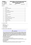
WW TONE
Elation Professional
6122 S Eastern Ave
Los Angeles, Ca 90040
www.elationlighting.com
Thank you for your patronage. We are confident that our excellent products and service can
satisfy you. For your own safety, please read this user manual carefully before installing the
device.
In order to install , operate, and maintain the lighting safety and correctly. We suggest that the
installation and operation should be done by the verified technician and follow the instruction
strictly.
Every person involved with the installation, operation and maintenance of this device has to:
-be qualified
-follow carefully the instructions of this manual
INTRODUCTION:
Thank you for having chosen this professional LED moving head.
You will see you have acquired a powerful and versatile device.
Unpack the device. Inside the box you should find:
1. One XLR connection cable
2. A power cable
3. One safety rope
4. Manual
5. Barn-door
6. Frost filter
Please check carefully that there is no damage caused by transportation. Should there be any,
consult your dealer and don’t install this device.
Features
·LED type: BXRA-W3000
·Channel mode: 2 channels
·Strobe effect with 1-13 flashes per second and pulse effect
·4 digit LED display
·Display: Can be changed 180° reverse to fit for different installation position.
·Software-upload by optional accessory via DMX line
Overview
1) Display
2) Mode/Esc-button
3) Up-button
4) Down-button
5) Enter-button
6) Safety eyelet
7) Power output
8) Power inpot/Fuse
9) 3-Pin DMX in
10) 3-Pin DMX out
11) Fixation screw
12) Floor-stand
SAFETY INSTRUCTIONS
This device has left the factory in perfect condition. In order to maintain this condition and to
ensure a safe operation, it is absolutely necessary for the user to follow the safety instructions and
warning notes written in this user manual.
Important:
Damages caused by the disregard of this user manual are not subject to warranty. The
dealer will not accept liability for any resulting defects or problems.
If the device has been exposed to temperature changes due to environmental changes, do not
switch it on immediately. The arising condensation could damage the device. Leave the device
switched off until it has reached room temperature.
This device falls under protection-class I. Therefore it is essential that the device be earthed.
The electric connection must carry out by qualified person.
Make sure that the available voltage is not higher than stated at the end of this manual.
- 1 -
XM605-V1.0-NR
Make sure the power cord is never crimped or damaged by sharp edges. If this would be the case,
replacement of the cable must be done by an authorized dealer.
Always disconnect from the mains, when the device is not in use or before cleaning it. Only
handle the power cord by the plug. Never pull out the plug by tugging the power cord.
During initial start-up some smoke or smell may arise. This is a normal process and does not
necessarily mean that the device is defective, it should decrease gradually.
Please don't project the beam onto combustible substances.
If the external flexible cable or cord of this luminaire is damaged, it shall be exclusively replaced
by the manufacturer or his service agent or a similar qualified person in order to avoid a hazard.
Please be aware that damages caused by manual modifications to the device are not subject
to warranty. Keep away from children and non-professionals.
GENERAL GUIDELINES
This device is a lighting effect for professional use on stages, in discotheques, theatres, etc., the
device was designed for indoor use only.
This fixture is only allowed to be operated with the max alternating current which stated in the
technical specifications in the last page of this manual.
Lighting effects are not designed for permanent operation. Consistent operation breaks may
ensure that the device will serve you for a long time without defects.
Do not shake the device.Avoid brute force when installing or operating the device.
While choosing the installation-spot, please make sure that the device is not exposed to extreme
heat, moisture or dust. Please don't project the beam onto combustible substances.The minimum
distance between light-output from the projector and the illuminated surface must be more than
0,1 meter.
If you use the quick lock cam in hanging up the fixture, please make sure the quick lock fasteners
turned in the quick lock holes correctly.
Operate the device only after having familiarized with its functions. Do not permit operation by
persons not qualified for operating the device. Most damages are the result of unprofessional
operation.
- 2 -
XM605-V1.0-NR
Please use the original packaging if the device is to be transported.
For safety reasons, please be aware that all modifications on the device are forbidden.
If this device will be operated in any way different to the one described in this manual, the
product may suffer damages and the guarantee becomes void. Furthermore, any other operation
may lead to short-circuit, burns, electric shock, lamp explosion, crash, etc.
INSTALLATION INSTRUCTIONS
a) Mounting the device
The applicable temperature for the lighting is between -25°C to 45°C. Do not use the lighting
under or above the temperature.
The installation of the effect has to be built and constructed in a way that it can hold 10 times the
weight for 1 hour without any harming deformation.
The installation must always be secured with a secondary safety attachment, e.g. an appropriate
safety rope.
Never stand directly below the device when mounting, removing or servicing the fixture.
The operator has to make sure the safety relating and machine technical installations are approved
by an expert before taking the device into operation for the first time.
These installations have to be approved by a skilled person once a year.
Overhead mounting requires extensive experience, including amongst others calculating
working load limits, installation material being used, and periodic safety inspection of all
installation material and the device. If you lack these qualifications, do not attempt the
installation yourself. Improper installation can result in bodily injury.
T he el ec tri c c onnec ti on m ust onl y b e c arri ed out b y a qu al if i ed el ec tri c i an. Before mounting make sure that the installation area can hold a minimum point load of 10 times
the device’s weight.
Connect the fixture to the mains with the power plug.
- 3 -
XM605-V1.0-NR
Installation via the Omega holders
a) Fixed the clamp on the bracket by tighten up the M12 screw on the bracket to the Ф13 hole in
the middle of the bracket.
b) Insert the quick-lock fasteners of the first Omega holder into the respective holes on the
bottom of the device. Tighten the quick-lock fasteners fully clockwise.
c) Install the second Omega holder.
d) Pull the safety-rope through the holes on the bottom of the base and over the trussing system
or a safe fixation spot. Insert the end in the carabine and tighten the safety screw.
Notice: this step is quite important to ensure that the fixture will not drop out by the
damage of the clamp.
DMX-512 control connection
Connect the provided XLR cable to the female 3-pin XLR output of your controller and the other
side to the male 3-pin XLR input of the moving head. You can chain multiple
Moving head together through serial linking. The cable needed should be two core, screened
cable with XLR input and output connectors. Please refer to the diagram below.
- 4 -
XM605-V1.0-NR
Address 1
Address 3
Address5
DMX-512 connection with DMX terminator
For installations where the DMX cable has to run a long distance or is in an electrically noisy environment,
such as in a discotheque, it is recommended to use a DMX terminator. This helps in preventing corruption of
the digital control signal by electrical noise. The DMX terminator is simply an XLR plug with a 120 Ω resistor
connected between pins 2 and 3,which is then plugged into the output XLR socket of the last fixture in the
chain. Please see illustrations below.
Projector DMX start address selection
All fixtures should be given a DMX starting address when using a DMX signal, so that the correct fixture
responds to the correct control signals. This digital starting address is the channel number from which the
fixture starts to “listen” to the digital control information sent out from the DMX controller. The allocation of
this starting address is achieved by setting the correct number on the display located on the base of the device.
You can set the same starting address for all fixtures or a group of fixtures, or make different address for each
fixture individually.
If you set the same address, all the units will start to “listen” to the same control signal from the same channel
number. In other words, changing the settings of one channel will affect all the fixtures simultaneously.
If you set a different address, each unit will start to “listen” to the channel number you have set, based on the
quantity of control channels of the unit. That means changing the settings of one channel will affect only the
selected fixture.
In the case of the move head, which is a 2 channel fixture, you should set the starting address of the first unit to
1, the second unit to 3 (2 + 1), the third to 5 (2 + 3), and so on.
- 5 -
XM605-V1.0-NR
Note:
The modes of DMX 512 data are shown via the display:
DMX OK
NO DMX
1. After switching on, the device will automatically detect whether DMX 512 data is received or not. If the data
is received, the display will show "A.001" with the actually set address. If there is no data received at the
DMX-input, the display will flash "A001" with the actually set address.
This situation can occur if:
- the 3 PIN XLR plug (cable with DMX signal from controller) is not connected with the input of the device.
- the controller is switched off or defective, if the cable or connector is defective or the signal wires are swap in
the input connector.
It’s necessary to insert the XLR termination plug (with 120 Ohm) in the last lighting in the link in order to
ensure proper transmission on the DMX data link.
Control Board
There are four keys on the control panel , which could be used to set the address, turn ON/OFF, operating the
program and reset.
[Mode/Esc] press this key to enter into edit mode. Press this key under the edit mode if you want to return to
previous menu. it will exit from edit mode 60 seconds after the last keypress
[UP] screen will flash when pressing this key in normal mode, the adress value will increasing. Keep pressing
this key, the address value will increase rapidly. it will exit from flash 60 seconds after the last keypress. Press
this key under edit mode, you can choose the function you want from the buttom up in the menu.
[DOWN] screen will flash when pressing this key in normal mode, the adress value will idecreasing. Keep
pressing this key, the address value will decrease rapidly. it will exit from flash 60 seconds after the last
keypress. Press this key under edit mode, you can choose the function you want from the top down in the menu.
[ENTER] this key is functionless when in normal mode. Press this key under the edit mode, it will enter into
next menu.
- 6 -
XM605-V1.0-NR
A001~AXXX
<ADDR>
<RUN>
MODE
<DISP>
VALU
(AXXX)
DMX address setting
SLAV
ON/OFF
Set as Slave
RDMX
ON/OFF
Change address via DMX
AUTO
ALON/MAST
Run Auto program
VALU
D-XX
FLIP
ON/OFF
Flip display
D ON
ON/OFF
Delay shutting off LED display
D-00(DXXX) Display DMX value
Key lock
(Press the MENU button for 3
LOCK
SET
MANL
TIME
EDIT
ON/OFF
seconds to activate)
<FAIL>
OFF/HOLD/AUTO
Status while there is no DMX
<DFSE>
ON/OFF
Default setting
Power on to preserve the MANL
<POHO>
ON/OFF
settings
<FANS>
AUTO/HIGH/LOW
Fan’s mode select
<VER>
V-1.0~V-9.9
Software version
<WHIT
STRB>
Manual adjust intensity Manual adjust
WXXX
intensity.
SXXX
<LIFE>
0000~9999(HOURS)
Life time of machina running
<CODE>
CXXX
Passord of clear time ”038”
<CLFE>
ON/OFF
Clear machina running time
<STEP>
S-01~S-48
Select steps of program
REC.
RE.XX
Auto Save Scene
<SC01>
WHIT
WXXX
STRB
SXXX
FADE
XXX
~<SC48>
Edit the internal scenes
XXX.X(000.1S~999.9
TIME
S)
CEDT
ON/OFF
Edit program via controller
Default settings shaded
- 7 -
XM605-V1.0-NR
Main Menu Functions
- “MODE” - Function Mode:
<ADDR> - DMX address setting – This function is used to set or adjust the fixture’s
starting DMX address. Every device controlled by DMX has to have a unique starting
address. The addressing feature is what allows DMX to function properly. The DMX
address of a fixture is what allows it to communicate with a controller properly. The
DMX addressing also allows the fixture to ignore any DMX information coming from
the controller that is not meant specifically for the fixture. Because each fixture is
connected in a daisy-chain fashion it is imperative to assign a proper and unique
starting DMX address to each and every fixture. The DMX address is non-destructive
and will remain in the fixture’s memory even when the power to the unit is switched
off. Memory is backed-up and retain by an internal power source that should last
about five years.
“VALU” - Display the DMX 512 value of each channel
With this function you can display the DMX 512 value of each channel. The
display will automatically detail the changing DMX values as they are received
from the controller.
“SLAV” - Slave setting for Master/Slave Operation
With this function, you can define the device as slave for operation in
Master/Slave mode. Each slave setting will have a different function for a
dynamic lightshow without a controller.
“RDMX” - Address via DMX - This function allows the DMX address to
remotely be adjusted from a DMX console. This setting requires special settings
for both the controller and the fixture. RDMX is on by default. For operational
instructions please see Section 9/Page 23 of this manual “Remote DMX
addressing.”
<RUN> - Internal Program Settings
This function allows the internal programs to run in either stand-alone or master/salve
mode. In “Master” mode the fixture will send DMX data to other fixtures connect via
the DMX chain. In “Alone” mode the fixture will operate as a single fixture. The
program for this mode is selected in the “Select program” section of the control
- 8 -
XM605-V1.0-NR
menu. You can set the number of steps under “Edit program”. You can edit the
individual scenes under “Edit scenes”. With this function, you can run the individual
scenes either automatically, i.e. with the adjusted Step-Time.
<DISP> - Menu Display Settings
This function allows the internal programs to run in either stand-alone or master/salve
DMX chain. In “Alone” mode
“VALU” - Display the DMX 512 value of each channel
This function will electronically display the current DMX value for any channel
that is
currently being adjusted. The display will automatically detail the
changing DMX
values as they are received from the controller. This
function is “off” by default.
“FLIP” – This function will flip the display readout by 180˚ allowing for
better visualization when the fixture is mounted in an inverted position.
“D ON” – The display is designed to turn off during normal operation to
avoid excessive light in situations that require an extremely dark environment.
This function will adjust the time delay the fixture will remain on before it turns off.
This function is disabled as default.
LOCK –This function allows you to lock the keys.
This function activates the automatic key lock command. If this function is
activated, all menu keys will automatically lock whit in 15 seconds of the last
menu function. To temporarily deactivate the key lock function, press and hold
down the Mode/Esc-button for 3 seconds.
“SET” – Fixture Personality Settings:
These functions set specific running modes and operating parameters.
- 9 -
XM605-V1.0-NR
<FAIL> DMX Fault Protection
This function dictates how the fixture will operate in the event DMX signal is
suddenly lost while operating in DMX mode. The three fail safe modes are; 1)
“OFF” which will blackout all light output. 2) “HOLD,” which will hold the last DMX
command, or 3 “AUTO,” which will put the fixture in sound-active mode.
<DFSE> - Restore Default
This function is used to restore the factory settings of the device. All settings will be
set back to the default values (shaded). Any edited scenes will be lost.
- Power on to preserve the MANL settings
This function will preserve all the manual setting that are made in the “MANL”
menu section. If this function is not activated all manual settings will be lost once
the fixture is tuned off.
- This function is used to change the functionality of the internal cooling
fans. Follow the procedure below to access the fan menu:
1. Access the main menu.
2. Tap the UP or DOWN button until “SPEC” is displayed, press ENTER.
3. Tap the UP or DOWN button until “FANS” is displayed, press ENTER.
4. The display will show “HIGH/AUTO/LOW”.
5. Press UP or DOWN button to select “HIGH” , “AUTO” or “LOW”.
6. Press ENTER to confirm.
7. Press MODE/ESC to return to the main menu.
<VER> Software Version
This function will display the current firmware version.
“MANL” – Manual Fixture Settings:
This function allows the each of the ten DMX channels to be controlled manually.
This will allow the fixture to be preset to a specific color or built-in program without the
use of a DMX console.
1. Select “MANL” by pressing [UP] or [DOWN] button.
2. Press [ENTER], the display shows “WHIT”, “STRB” .
- 10-
XM605-V1.0-NR
3. Press [UP] or [DOWN] button to select “WHIT”, “STRB””
4. Press [ENTER] to confirm or Press [MODE/ESC] to return to the main menu.
“TIME” – Operating Hours
These functions will detail different time functions associated with the fixture.
<LIFE> (0000~9999 Hours)
This function tracks the running time of the fixture from the point it was last
cleared.
none
to track
Where “XXXX ”represents the total number of running hours. This time is
destructive and will remain in the fixtures memory indefinitely. Use this time
rentals or show durations.
<CODE> Clear run time access code
This lock-out code prevents the current run time from being erased accidently.
The
access code is “038”
<CLFE> Clear Fixture Run Time
This function resets the run time to zero.
“Edit” Internal Program Settings:
The fixture comes equipped with a built-in DMX recorder that allows custom
programs to be installed and recalled directly from the fixture’s control board.
Programs can be created and stored using the fixture’s control board or by using an
external DMX controller. For detailed instructions on how to complete this task please
see “Working with Built-In Programs” Section 11/ Page 27.
Select program – This function allows the user to select one of ten of the user
defined built-in programs. This program is then accessed in “Function Mode”
under
“Program Run.”
REC – Auto save function.
Edit program – This function allows the user to edit the built-in programs.
- 11-
XM605-V1.0-NR
Edit Scenes – This function allows the user to edit or define the actual scenes
that
are stored in the user defined built-in programs that are accessed in the
previous
step.
CEDT - Edit program using a external controller.
Editing procedure 1: Using the control board only.
1. Access the main menu.
2. Tap the UP button until “EDIT” is displayed and press ENTER.
3. The display will show “SC-01”, this stands for the scene number. For example,
“SC-01” is displayed, it means you will be editing scene 1, press ENTER. You
can change the scene number by tapping the UP button.
4. Press ENTER, the display will show “C-01,” this represents the channel
number. If “C-01” is displayed, you will be editing the fixture’s channel 1
value of the selected scene, press ENTER. You can change the channel
number by tapping the UP button.
5. The display will show the DMX value for the channel that is being edited. It will
be displayed as “11XX,” it stands for Channel 11 of the editing scene, the
DMX value is “XX.”
6. Adjust the DMX value by tapping the UP button, until you get the expected
effect for this channel.
7. Press ENTER to enter the editing of the other channels of the scene.
8. Repeat steps 5-8, until you finish setting all the DMX values for all the
channels of this scene, each scene can have 16 channels maximum.
9. Once all the channels are completed, the display will begin to flash “TIME,”
this indicates the time needed to run this scene.
10. Press ENTER to edit the time needed, the display shows “TXXX”, “XXX”
represents the time needed to run this scene. For example, “T002” means
scene 1 needs 0.4 seconds to run, “T-15” means this scene needs 3.0
seconds to run. Note: “XX” is always 0.2 seconds not one second.
11. Adjust the time needed by tapping the UP button.
12. Press ENTER to save the settings for the scene you are editing, the display
will change to the next scene automatically.
13. Repeat steps 3-12 to edit other scenes, you can edit and save 48 scenes
- 12-
XM605-V1.0-NR
maximum.
14. Press MODE/ESC to exit and save your edited scene into the fixtures internal
memory. The number of steps can be defined under “EDIT” and the scenes
can be called up under “Run.” To run the scenes see page 30.
Editing procedure 2: Using an external controller.
1.
Call up the first scene in your controller now.
2.
Select “SC01” by pressing the UP or DOWN buttons.
3.
Press MODE/ESC, the display shows “SC01”.
4.
Press MODE/ESC, the display shows “C-01”.
5.
Select "CEDT" by pressing the UP or DOWN buttons.
6.
Press MODE/ESC, the display shows "OFF".
7.
Press UP, the display will read "ON".
8.
Press
MODE/ESC,
the
display
shows
"SC02".
You
successfully
downloaded the first scene.
9.
Adjust the Step-time as described above.
10. Call up the second scene in your controller now.
11. Repeat steps 5-11 until all desired scenes are downloaded.
12. Press MODE/ESC to exit. The number of steps can be defined under
“STEP” and the scenes can be called up under “RUN.”
- 13-
XM605-V1.0-NR
INSTRUCTIONS ON USE:
DMX channel´s functions and their values :
Channel
Value
Function
2CH
White LED
:
1
0-255
White ( 0-Black , 255-100% White )
Shutter, strobe:
0-31
Led trun off
32-63
Led turn on
64-95
Strobe effect slow to fast
2
96-127
Led turn on
128-159
Pulse-effect in sequences
160-191
Led turn on
192-223
Random strobe effect slow to fast
224-255
Led turn on
Instructions for installing the barn-door and frost filter:
For this device, the barn door and the frost filter can be installed separately or together.
1.When only install the frost filter, use the rotating clips on the lens cover to fix it.
2.When only install the barn door, loose the 4 M4 screws on the lens cover, put on the bar door and tighten the
screws.
3.When install the barn door and frost filter together, loose the 4 M4 screws, put on the frost filter and the bar n
door one by one, then tighten the screws.
- 14-
XM605-V1.0-NR
CLEANING AND MAINTENANCE
The following points have to be considered during the inspection:
1) All screws for installing the devices or parts of the device have to be tightly connected and must not be
corroded.
2) There must not be any deformations on the housing, color lenses, fixations and installation spots (ceiling,
suspension, trussing).
3) Mechanically moved parts must not show any traces of wearing and must not rotate with
unbalances.
4) The electric power supply cables must not show any damage, material fatigue or sediments.
Further instructions depending on the installation spot and usage have to be adhered by a skilled installer and
any safety problems have to be removed.
In order to make the lights in good condition and extend the life time, we suggest a regular
cleaning to the lights.
1) Clean the inside and outside lens each week to avoid the weakness of the lights due to
accumulation of dust.
2) Clean the fan each week.
3) A detailed electric check by approved electrical engineer each three month, make sure that
the circuit contacts are in good condition, prevent the poor contact of circuit from
overheating.
We recommend a frequent cleaning of the device. Please use a moist, lint- free cloth. Never use alcohol or
solvents.
There are no serviceable parts inside the device except for the lamp. Please refer to the instructions under
“Installation instructions”.
Should you need any spare parts, please order genuine parts from your local dealer.
TECHNICAL SPECIFICATIONS
Power supply: AC 100V-240V~, 50Hz/60Hz
Remark: errors and omissions for every information given in this manual excepted. All information is subject to
change without prior notice.
- 15-
XM605-V1.0-NR