1
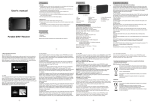
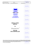
ZVR-510 RECEIVER USERS MANUAL SECURITY with VISION MEYERTECH LIMITED ISSUE 06 CONTENTS 1. ZVR-510 WELCOME 4 2. FEATURES 4 3. INSTALLATION 5 3.1 LINK SETTINGS 5 3.2 CONNECTING THE ZVR-510 5 3.3 ADDRESS SETTING 6 4. CONFIGURATION 4.1 LOGGING ONTO THE ZVR-510 7 7 4.1.1 LOGGING ON FROM THE ZVK-007 KEYBOARD 7 4.1.2 LOGGING ON FROM THE ZVK-008 KEYBOARD 7 4.2 KEY TABLES 8 4.2.1 ZVK-007 Key Table 8 4.2.2 ZVK-008 Key Table 8 4.3 HEAD FORMATTING 8 4.4 OSD MENU SYSTEM 9 4.4.1 HEAD FUNCTIONS 4.4.2 ALARM FUNCTIONS 11 4.4.3 MEMORY FUNCTIONS 12 4.4.4 DISPLAY FUNCTIONS 13 4.4.5 MISCELLANEOUS FUNCTIONS 13 LOGGING OFF FROM THE ZVR-510 14 4.5.1 LOGGING OFF FROM A ZVK-007 14 4.5.2 LOGGING OFF FROM ZVK-008 14 4.5 5. DIAGNOSTICS 9 15 5.1 SELF TEST 15 5.2 ON SCREEN DIAGNOSTICS 15 Page 2 MEYERTECH LIMITED ISSUE 06 6. DEFAULT CONFIGURATION 16 7. SPECIFICATIONS 18 7.1 ELECTRICAL 18 7.2 PHYSICAL 18 7.3 FUNCTIONS 18 8. TROUBLE SHOOTING GUIDE 20 9. DECLARATION OF CONFORMITY 21 10. PRODUCT WARRANTY 22 11. APPENDIX A PCB OVERVIEW 23 12. APPENDIX B CONNECTION DIAGRAM 24 Whilst every effort has been made to confirm the information in this document is correct, MEYERTECH LIMITED cannot accept any liability for any errors, omissions and or incorrect information contained within this document. No part of this document may be reproduced or distributed in any form or by any means without prior written consent from MEYERTECH LIMITED. MEYERTECH LIMITED are committed to continuous product development and therefore reserve the right to change specifications without notice. 1997-2004 ALL RIGHTS RESERVED. Page 3 MEYERTECH LIMITED ISSUE 06 1. ZVR-510 WELCOME Thank you for purchasing the ZoneVu ZVR-510 Telemetry Receiver. The ZVR-510 fully exploits the benefits of high performance DC variable speed control. The receiver operates over Coax based MEYERTECH VICTA telemetry or twisted pair RS422, and is compatible with the full range of ZoneVu products. R-510 WELCOME 1 ZVR- 2. FEATURES ♦ Variable speed Pan, Tilt Zoom and Focus ♦ Simultaneous Pan, Tilt and Zoom ♦ Softstop facility ♦ Auto/Manual Iris Control ♦ PWS (Peak White Suppression) ♦ Wash, Wipe and Lamp ♦ Latching Auxiliary ♦ Momentary Auxiliary ♦ Self Test Mode ♦ System Diagnostics ♦ Programmable Preset ♦ Programmable Privacy Zones ♦ Programmable Ordered and Random Patrols ♦ 6 Alarm Inputs + Anti-Tamper and Camera Fail Alarms ♦ On Screen Display Configuration ♦ COAX/RS422/RS485 Transmission 3 Page 4 INSTALLATION MEYERTECH LIMITED ISSUE 06 3. INSTALLATION To obtain the optimum performance from your ZVR-510 please take time to read this manual before commencing installation. If you have any questions or problems our staff will be pleased to assist you on the technical helplines listed on page 26. WARNING THIS EQUIPMENT CONTAINS HAZARDOUS VOLTAGES. THIS EQUIPMENT MUST BE EARTHED TO PREVENT FIRE OR SHOCK HAZARD. DO NOT EXPOSE THIS EQUIPMENT TO RAIN OR MOISTURE. Unpack the ZVR-510 and check the contents against the list below. ♦ ♦ ZVR-510 PCB Transformer 20V 100VA 3.1 LINK SETTINGS Links N.O. and N.C. are used to select Alarm contact types. NEVER connect both N.O. and N.C. N.C. N.O. LD LENS 422/485 422 ( x2 ) Fit for Normally Closed Contacts. Fit for Normally Open Contacts. Fit for ZVR-510 Selects 6 or 12V camera drive level. Sets up serial port. (Link out - 422 ; Link in - 485) Fit for receiving via RS422 and transmitting via VICTA COAX. Unfitted receives and transmits via VICTA COAX Note : For Link locations see Appendix A on page 23. VC1 Variable trimmer capacitor adjusts caption widths of OSD text. 3.2 CONNECTING THE ZVR-510 Connect up the ZVR-510 in accordance with the accompanying wiring diagram, paying special attention to the maximum ratings and the notes below. 1. The ZVR-510 MUST be Earthed at the AC input supply terminal. 2. NEVER run cables directly under the PCB as this may interfere with the operation of the Telemetry ZVR-510 and other camera head equipment. 3. ALWAYS use Screened cables for low voltage and signal cables ensuring the screen is connected to 0V or Earth. Page 5 MEYERTECH LIMITED ISSUE 06 4. AVOID looming cables of differing characteristics together E.G. Video cables with cables carrying mains power. 5. If the ZVR-510 is to be operated over twisted pair cable ensure the screen is connected to 0V. 6. If N/O alarms are selected link-out unused inputs to the alarm common. 7. The maximum cable run for Twisted Pair is typically 2Km. 8. The maximum cable run for VICTA is typically 750m. 9. The maximum number of Telemetry Receivers that can be connected to a driver output is 32. 2 10. The cable used to wire the secondary of the transformer should be a minimum of 0-5mm . 11. Observe the polarity of the brake wiring. Incorrect connection will result in vibration when coming out of a mechanical end stop. To test the ZVR-510 locally press the SELF-TEST switch for approximately 3 seconds. The ZVR-510 will then perform a self test cycle exercising each function in turn. Status LED’s are provided for +12V and Comms. Received (RXD). 3.3 ADDRESS SETTING To set the ZVR-510 receiver address: 1. Press and Hold the Self Test Button on the ZVR-510. (See PCB Overview) 2. Apply power to the ZVR-510. 3. When the ZVR-510 powers up, an On Screen Display will display the current receiver address and give instructions for changing the address. 4. The Self Test button is used to change the receiver address by stepping from left to right through three numeric fields. These are the Hundreds, Tens and Units which make up the ZVR-510 network address. A flashing cursor highlights the current field. 5. Momentary key presses increment the value displayed within the current field. 6. A key press of longer than 2 seconds steps to the next field. Either Hundredths to Tens, Tens to Units or Units back to Hundredths. 7. Ensure that the programmed receiver address is valid. 8. A key press of longer than 5 seconds accepts the displayed address and the ZVR-510 continues to power up as normal. Page 6 MEYERTECH LIMITED ISSUE 06 4. CONFIGURATION The ZVR-510 should now be configured by logging onto the receiver from a ZVK-007 keyboard and following the On Screen Menus. 4.1 LOGGING ONTO THE ZVR-510 4.1.1 LOGGING ON FROM THE ZVK-007 KEYBOARD Access to Telemetry Receiver Configuration is achieved by logging on to the SUPERVISOR LEVEL of the keyboard. 1. Log On to the ZVK-007 at Supervisor Level. 2. Use the MODE Key to step through the Menu options to ZVR CONFIG Select using the ENT key. 3. Use the MODE Key to step through the various receiver options to ZVR-510. Select using the ENT key. 4. Press the PROG Key to enter the On Screen Display Menu system. ZVK-007 now enters TALK mode with the ZVR-510 Receiver. 5. The Right Hand Joystick control is used to navigate the OSD Menu System. The current selected option is indicated by flashing text. 4.1.2 LOGGING ON FROM THE ZVK-008 KEYBOARD Access to Telemetry Receiver Configuration is achieved by logging on in the following manner. 1. Ensure PTZ mode is off. (Key ‘U’, LED=OFF) 2. Type ∗ZVR#. ZVR-510 enters the On Screen Display Menu system. ZVK-008 now enters TALK mode with the ZVR-510 Receiver. 3. To navigate the OSD Menu System, select the option by pressing the appropriate upper case character. The selected option is indicated by flashing text. Confirm by pressing #. 4. After exiting from the ZVR-510 menus type ∗Q to exit TALK mode with the ZVR-510 Receiver. Page 7 MEYERTECH LIMITED ISSUE 06 4.2 KEY TABLES 4.2.1 ZVK-007 KEY TABLE The following ZVK-007 keys are used to configure the Receiver. ENT Proceed to the selected option. Also used to Abort Endstop and Preset Positioning. HOLD Used to Save Endstop and Preset positions. MODE/SHIFT Toggle between Alphabetic and Numeric Keys. SPACE Toggle between options enclosed within quotes. E.g. [ option ]. DEC Toggles between Upper and Lower Cases when entering Text. << Used to delete text characters to the left of the cursor position. >> Used to delete text characters at and to the right of the cursor position. 4.2.2 ZVK-008 KEY TABLE The following ZVK-008 keys are used to configure the Receiver. # Proceed to the selected option. S Used to Save Endstop and Preset positions. X Used to abort Endstop and Preset positions. SPACE Toggle between options enclosed within quotes. E.g. [ option ]. DEL Backspace delete. HOME Press to access joystick control when controlling PTZF. 4.3 HEAD FORMATTING It is important to configure the following ZVR-510 parameters in the following order before attempting to configure any other parameters. This is only required if the Pan and Tilt head or lens is fitted with feedback pots. 1. Feedback Pots (Head Functions Menu). 2. Check joystick control. Make any corrections to joystick control within the PTZF Swap Menu (Head Functions Menu). 3. Set the End Stops for Pan, Tilt, Zoom and Focus (optional). 4. Set Head Inertia and Drive Level for Slow Speed control to suit the Pan & Tilt Head being used. Page 8 MEYERTECH LIMITED ISSUE 06 4.4 OSD MENU SYSTEM Configuration is divided into five sections within the Setup Main Menu of the On Screen Display. To select a specific category ZVK-007 navigate the OSD menu using the Right Hand Joystick and select with the ENT key. ZVK-008 navigate the OSD menu by pressing the character shown as upper case in the option text. Select with the # key. ZVR-510 Setup Main Menu Head functions aLarm functions Memory functions Display functions mIsc. functions Abandon changes Save change Note : Early versions of ZVK-007 (software issues prior to 2-0) should be used to program the ZVR-510 in the same way as the ZVK-008, with the following exception: Do not use the joystick to navigate menu’s. Use upper case letters as per the ZVK-008. If joystick is used by mistake, press ‘X’ to recover. 4.4.1 HEAD FUNCTIONS The options within this Menu refer to the camera head. It is important to use the facilities within this menu to customize the receiver to the type of head the receiver is connected to. ZVR-510 Head Functions Ptzf swap Feedback pots Endstops speed Table errOr table Softstop PTZF Swap The PTZF SWAP facility is an engineering function to reverse the polarities of the Pan, Tilt, Zoom and Focus drives. When a receiver is initially installed the Page 9 MEYERTECH LIMITED ISSUE 06 direction of PTZF functions should be checked and reconfigured where necessary. Feedback Pots The receiver tests head potentiometers to determine drive feedback and direction. This also determines whether the head is capable of presets. During this operation each function (Pan, Tilt, Zoom, Focus) will be exercised by the receiver as a integrity test. Any faults will be displayed on-screen. Endstops These can be set for Pan, Tilt, Zoom and Focus. Alternatively, they can be switched off. Speed Table Eight head speeds can be programmed corresponding to the eight grades of sensitivity on the right hand joystick. Using this table, it is possible to set up a Joystick speed curve. An example is shown below. Head Speed Drive Level 1 2 3 4 5 6 7 8 1 2 4 7 12 18 24 32 Error Table Eight error Example Speed Curve Head Speed values can be programmed corresponding to the 35 30 25 20 15 10 5 0 Drive Level 1 2 3 4 5 6 7 8 eight speed values set in the Speed Table. Using this table, it is possible to control the rate that the head decelerates towards a preset. The value programmed correlates to a distance away from a target with a head speed. Two example tables are given below. Standard Speed Head Page 10 High Speed Head Head Speed Error Head Speed Error 1 2 3 4 5 6 7 8 2 5 9 14 20 27 35 44 1 2 3 4 5 6 7 8 2 30 80 120 160 200 280 400 MEYERTECH LIMITED Softstop ISSUE 06 This feature controls the deceleration of the camera head, reducing wear and eliminating system abuse. Set as either Active or Inactive. 4.4.2 ALARM FUNCTIONS The ZVR-510 has the capability to detect and report six contact alarms, one tamper alarm and one camera fail alarm. The six alarms and tamper alarm can be set to trigger from Normally Open or Normally Closed contacts via a link on the PCB. The menu options allows the alarms to be globally enabled or disabled. If a Camera Fail alarm occurs whereby Video signal stop being transmitted to the ZVR-510, the OSD facility ensures that Alarm, Dynamic Text and Static Text Information continues to be displayed Talk Mode - VICTA, RS422/485, VICTA+RS4xx or None Alarm Status - On or Off ZVR-510 Alarm Functions Talk mode [VICTA Alarm status [ON] ] Return to main menu Page 11 MEYERTECH LIMITED ISSUE 06 4.4.3 MEMORY FUNCTIONS The options within this Menu refer to the ZVR-510 receivers programmed positions, patrols and text displayed. ZVR-510 Memory Functions Presets Ordered patrol rAndom Patrol privacy Zones Static caption Dynamic captions Load defaults Return to main menu Presets Enter up to sixteen preset camera positions and one Home position (Preset 0) using the Presets Sub Menu. Select Presets and enter the required preset number from 0-16. Using the Left and Right hand joysticks, position the camera as required (press HOME first on ZVK-008 to access PTZF). Press HOLD (ZVK-007) / S (ZVK-008) to save or ENT (ZVK-007) / X (ZVK-008) to abort. Ordered Patrol Program an Ordered Patrol sequence of up to sixteen positions consisting of any of the sixteen preset positions or the Home preset, in any order. A preset time which controls the length of time the camera stays at each preset position may be set individually for each point in the patrol sequence. Random Patrol Program a Random Patrol, by declaring the maximum preset number. The order in which the presets are recalled and length of time spent at each preset will be random. Privacy Zones Up to four privacy zones can be setup. This involves using the monitor display to mark the top left and bottom right corners of the privacy zone, using the bottom right corner of the monitor as an approximate marker. Then set the Zoom point. This gives the option to peruse a scene from a distance, but gives privacy when zoomed in. Static Caption On Screen Display text. Up to twelve Alpha-numeric characters may be used. Dynamic Captions Text changes as the camera is panned through 360°. Up to sixteen captions each comprising up to twenty four Alpha-numeric characters may be used. Page 12 MEYERTECH LIMITED Load Defaults ISSUE 06 Loads default configurations. For further information refer to the Default Configuration section of this manual. 4.4.4 DISPLAY FUNCTIONS The options within this menu allow the user to configure the On Screen Display. ZVR-510 Display Functions Text display text Colour text Position Static caption Dynamic captions [ON] [White] [Bottom] [ON] [ON] Return to main menu The features and options available are listed below. Text Display - On or Off Text Colour - White or Black Text Position - Top or Bottom Static Caption - On or Off Dynamic Captions - On or Off 4.4.5 MISCELLANEOUS FUNCTIONS ZVR-510 Miscellaneous Functions head Type [ Normal ] head Inertia [ 3] head Drive level [ 3] iris Video level [50] iris Peak average [25] Return to main menu The options within this menu allow the user to define other functions of the ZVR-510 which do not fall into any of the previous menus of the On Screen Display. Page 13 MEYERTECH LIMITED ISSUE 06 Head Type defines the type of head in terms of speed and head rotation. A Normal head is one that could be described as of average speed without the ability to continually rotate. The Head Type can be set to some combination of Normal, Fast and/or Continuous. If the Head Type is not set correctly then testing of the Feedback pots will not operate correctly which will result in incorrect preset operation. Head Inertia and Head Drive Level are engineering functions used to configure the SLOW SPEED feature. Iris Video Level. This option configures the Auto Iris brightness level. If this value is increased, the video image will become brighter. Factory preset to 50. Iris Peak Average. Factory preset to 25. Configuration of these features would have been carried out by the system installer and SHOULD NOT be adjusted by the user. Experimentation of these parameters may be required to find the optimum setting for a particular type of head so that the slow speed range is as smooth as possible. 4.5 LOGGING OFF FROM THE ZVR-510 4.5.1 LOGGING OFF FROM A ZVK-007 1. Having configured the ZVR-510 Receiver, return to the Main Menu. Using the Right Hand Joystick control, select SAVE CHANGES or ABANDON CHANGES. Confirm selection by pressing the ENT key. IMPORTANT : At this point, the ZVK-007 is still in communication with the ZVR-510 and must be logged off in order to resume normal operation. 2. Press ESC to disconnect from the ZVR-510 Telemetry Receiver. 3. Press ESC to return to the ZVR CONFIG Menu. 4. Press ESC to Log off the ZVK-007 keyboard. 4.5.2 LOGGING OFF FROM ZVK-008 1. Having configured the ZVR-510 Receiver, return to the Main Menu. Select Save changes (S) or Abandon changes (A). Confirm selection by pressing the # key. IMPORTANT : At this point, the ZVK-008 is still in communication with the ZVR-510 and must be logged off in order to resume normal operation. Page 14 MEYERTECH LIMITED ISSUE 06 2. After exiting from the ZVR-510 menus type ∗ Q # to exit TALK mode with the ZVR-510 Receiver. 5. DIAGNOSTICS There are two forms of system diagnostics supported on the ZVR-510. 5.1 SELF TEST By pressing and holding the Self Test button for approximately three seconds, the ZVR-510 will enter a Self Test Mode. The unit will exercise Pan, Tilt, Zoom, and Focus functions. 5.2 ON SCREEN DIAGNOSTICS Log On to the ZVR-510 at Supervisor Level and select ZVR CONFIG using the MODE key. Step through the Receiver options to ZVR-510. Press the F1 key to Enable/Disable the On Screen Diagnostics. Only available through ZVK-007 keyboard. Preset Feedback Values Pan :123 Zoom :432 Tilt :876 Focus :457 Camera 1 Sector 2 Once this facility has been enabled, the Preset Feedback Values will remain on the Monitor display until disabled through the supervisor mode. The displayed Feedback Values are continually updated giving the user a quantitative measure of the Camera’s Pan, Tilt, Zoom and Focus performance. Page 15 MEYERTECH LIMITED ISSUE 06 6. DEFAULT CONFIGURATION Default Configurations as a result of Load Defaults (within Memory Functions Menu) or factory preset conditions. Head Functions PTZF Swap Pan Tilt Zoom Focus [Normal] [Normal] [Normal] [Normal] Feedback Pots Pan Tilt Zoom Focus [Not Available] [Not Available] [Not Available] [Not Available] Endstops Pan Tilt Zoom Focus [Not Available] [Not Available] [Not Available] [Not Available] Speed Table Head Speed = Head Speed = Head Speed = Head Speed = Head Speed = Head Speed = Head Speed = Head Speed = 1 2 3 4 5 6 7 8 Drive Level = 4 Drive Level = 8 Drive Level = 12 Drive Level = 16 Drive Level = 20 Drive Level = 24 Drive Level = 28 Drive Level = 32 Error Table Head Speed = Head Speed = Head Speed = Head Speed = Head Speed = Head Speed = Head Speed = Head Speed = 1 2 3 4 5 6 7 8 Error Level = 2 Drive Level = 5 Drive Level = 9 Drive Level = 14 Drive Level = 20 Drive Level = 27 Drive Level = 35 Drive Level = 44 Softstop [Inactive] Alarm Functions Talk Mode Alarm Status [VICTA] [ON] Memory Functions Presets Ordered Patrol Random Patrol Privacy Zones Static Captions [Undefined] [Undefined] [Undefined] [Undefined] Page 16 MEYERTECH LIMITED ISSUE 06 Caption = “Meyertech” Dynamic Captions Caption = “SECTOR 1” to “SECTOR 16” Display Functions Text Display Text Colour Text Position Static Caption Dynamic Captions [ON] [White] [Bottom] [ON] [ON] Miscellaneous Functions Head Type [Normal] Head Inertia [ 5] Head Drive Level [15] Iris Video Level [50] Iris Peak Average [25] Page 17 MEYERTECH LIMITED ISSUE 06 7. SPECIFICATIONS 7.1 ELECTRICAL POWER INPUT - 20VAC via MEYERTECH supplied transformer 110V or 240V +/- 10% 50- 60Hz AC direct to PCB 20VAC 50 - 60 Hz FUSING - 3.15 AT VIDEO - Input 1V pk - pk composite - 75R terminated Output 1V pk - pk 7.2 PHYSICAL DIMENSIONS - PCB W110mm L 202mm H 38mm WEIGHT - 400 grams TEMPERATURE - Operational 0 Degrees to 40 Degrees C - Storage minus 20 Degrees to plus 60 Degrees C - Humidity 10% to 95% (Non-condensing) CONNECTORS - VIDEO - CAM/MON - POWER - FUNCTIONS - PRESETS - COMMS - TAMPER - ALARMS - AUX.2 COMMS - VICTA COAX - RS422 TWISTED PAIR - Two part screw terminal - Two part screw terminal - Two part screw terminal - Two part screw terminals - Two part screw terminal - Two part screw terminal - Two part screw terminal - 6 way Molex - 6 way Molex 7.3 FUNCTIONS WASH WIPE LAMP AUX1 AUX2 PAN TILT Page 18 - Relay 5A Max 240V AC Max with suppresser protection - Relay 5A Max 240V AC Max with suppresser protection - Relay 5A Max 240V AC Max with suppresser protection - Relay 5A Max 240V AC Max with suppresser protection - Relay 5A Max 240V AC Max with suppresser protection - Relay 2A Max 28V DC Max with suppresser protection - Relay 2A Max 28V DC Max with suppresser protection MEYERTECH LIMITED ZOOM* FOCUS* ALARMS PRESETS IRIS ISSUE 06 - Solid State 6/12V Nominal user selectable. Current limited - Solid State 6/12V Nominal user selectable. Current limited - 6 x Normally open or Normally closed external contacts and 1 Tamper - 16 x PTZF 10 bit A/D Resolution - Auto - Lens video input with Peak and Average adjustment 6V drive - Manual - Solid State drive 6V nominal current limited * User selectable 6/12V Nominal via link LENS. See PCB Overview. Page 19 MEYERTECH LIMITED ISSUE 06 8. TROUBLE SHOOTING GUIDE This Trouble Shooting Guide should be used in the first instance of encountering any problems with the ZVR-510. If problems persist, contact MEYERTECH on the Technical Helpline numbers given below. Symptom Solution Pan, Tilt, Zoom or Focus Joystick controls are reversed. If the Head used has feedback pots available : From the Main Menu, select Feedback Pots from the Head Functions Menu of the OSD Menu system. Systematically make each head option available. Test the joystick controls and correct using the PTZF Swap menu within the HEAD Functions Menu. If the Head does not have feedback pots available : Check field wiring. Whilst in the ZVR CONFIG Mode using the OSD Menu System the Pan &Tilt Head moves with Keyboard strokes. It is likely that the ESC key (ZVK-007) has been pressed inadvertently and the ZVK-007 is no longer transmitting configuration commands to the ZVR-510. Press ESC again and ensure that the ZVK-007 is no longer in TALK mode with the ZVR-510. Re-enter ZVR CONFIG and press PROG to access the receiver and continue in TALK mode. . Pan & Tilt Head struggles to move at the first point of the joysticks sensitivity. Check the Speed Table settings within the Head Functions menu. Increase the value in the Head Speed 1 field and ensure that the other Head Speed settings are altered accordingly. Pan & Tilt Head jerky in operation when SLOW speed mode is activated. Check the Head Inertia and Head Drive Level settings within the Miscellaneous Functions menu. Experimentation of these parameters may be required to find the optimum settings for the particular head in use. Alarms/Tamper are/is not reported. Ensure Alarm Status is ON within the Alarm Functions Menu is on and that the correct Talk Mode is selected. Ensure that the Normally Open/Normally Closed link setting is correctly set. Check field wiring. Page 20 MEYERTECH LIMITED ISSUE 06 9. DECLARATION OF CONFORMITY EC DECLARATION OF CONFORMITY ACCORDING TO ARTICLE 10 OF COUNCIL DIRECTIVE 89/336/EEC Manufacture’s Name: MEYERTECH LIMITED Manufacture’s Address: MEYERTECH Limited Office Block One Southlink Business Park Oldham OL4 1DE declares, that the product(s): Product Name : ZVR-510 Telemetry Receiver Model(s) : All Product Options : All conforms to the following Product Specifications : EN55022 EN50093 CLASS B Supplementary Information : MEYERTECH declare under our sole responsibility that the product to which this declaration relates, is in conformity with the protection requirements of council directive 89/336/eec on the approximation of the laws of the member states relating to electromagnetic compatibility. SIGNED - S K MEYERS DIRECTOR MEYERTECH LIMITED ISSUED THIS DAY 30th May 1996 European Contact : Meyertech Limited (Head Office), Office Block One, Southlink Business Park, Oldham, England, OL4 1DE. Page 21 MEYERTECH LIMITED ISSUE 06 10. PRODUCT WARRANTY MEYERTECH LIMITED warrants that at the time of shipment the products manufactured by Meyertech will be free from defects in material and workmanship. Should any defects appear within twelve months from date of shipment, Meyertech Limited shall at it’s sole discretion repair or replace the defective material. Such material shall not be accepted for return or repair without prior notification of Meyertech Limited. Return shipments to Meyertech Limited shall be at the customers expense. Meyertech Limited will return said equipment prepaid via best way. This warranty is in lieu of and excludes any and all other expressed or implied warranties of merchantability or fitness, or otherwise. Items manufactured by any supplier other than Meyertech Limited shall bear only the warranty made by the manufacturer of that product, and Meyertech Limited assumes no responsibility for the performance or reliability of that product. Meyertech Limited will not be liable for any special or consequential damages, or for loss, damages, or expense directly or indirectly arising from the use of the products, or any inability to use them either separately or in combination with any other equipment or material or from any other cause. This warranty does not extend to any product manufactured by Meyertech Limited which has been subject to misuse, neglect, accident, war, civil disturbance, terrorist acts, improper installation, act of God, or in violation of the instructions supplied by Meyertech Limited. Page 22 MEYERTECH LIMITED 11. APPENDIX A ISSUE 06 PCB OVERVIEW Page 23 MEYERTECH LIMITED 12. APPENDIX B Page 24 ISSUE 06 CONNECTION DIAGRAM MEYERTECH LIMITED ISSUE 06 NOTES Page 25 MEYERTECH LIMITED ISSUE 06 MEYERTECH LIMITED SECURITY with VISION Zebra Court White Moss View Greenside Way Manchester M24 1UN Sales Support Technical Support +44 (161) 6437956 +44 (161) 643 3992 Email : [email protected] Page 26 +44 (0) 161 6437956 Email : [email protected]