1
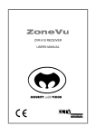
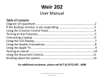
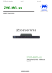
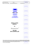
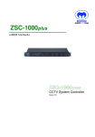
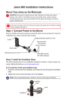
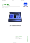
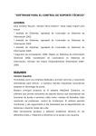
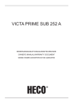
TELEMETRY RECEIVER USERS MANUAL ZVR-410 SECURITY with VISION LIMITED CONTENTS 1. ZVR-410 WELCOME .................................................................................................................................. 3 2. FEATURES .................................................................................................................................................... 3 INSTALLATION ................................................................................................................................................... 4 2.1 2.2 2.3 LINK SETTINGS .................................................................................................................................... 4 CONNECTING THE ZVR-410 ............................................................................................................... 5 CAMERA NUMBER ASSIGNMENT .................................................................................................... 5 3. SELF TEST DIAGNOSTICS........................................................................................................................ 6 4. SPECIFICATIONS ....................................................................................................................................... 6 4.1 4.2 ELECTRICAL ......................................................................................................................................... 6 PHYSICAL .............................................................................................................................................. 6 5. CONNECTION DIAGRAM ......................................................................................................................... 7 6. TROUBLE SHOOTING GUIDE ................................................................................................................. 8 7. DECLARATION OF CONFORMITY ........................................................................................................ 9 8. PRODUCT WARRANTY ........................................................................................................................... 10 9. DOCUMENT HISTORY ............................................................................................................................ 11 Whilst every effort has been made to confirm the information in this document is correct, MEYERTECH LIMITED cannot accept any liability for any errors, omissions and or incorrect information contained within this document. No part of this document may be reproduced or distributed in any form or by any means without prior written consent from MEYERTECH LIMITED. MEYERTECH LIMITED are committed to continuous product development and therefore reserve the right to change specifications without notice. 2002 ALL RIGHTS RESERVED. Z:\PRODUCTSarchive\Product Manuals\ZoneVu\Current Life Cycle\ZVR-410\internal\ZVR-410 User and Configuration Manual.doc Page2 1. ISSUE 02 ZVR-410 WELCOME Thank you for purchasing our ZoneVu ZVR-410 Telemetry Receiver. The ZVR-410 is a powerful, low cost telemetry receiver offering all the standard camera control functions required for AC heads plus Pan, tilt, Zoom and Focus presets. With the ability to operate over coax or twisted pair RS-422, the ZVR-410 is compact enough to be mounted easily inside a camera housing and on board self-test and diagnostic facilities minimize installation and commissioning time. MEYERTECH are dedicated to customer service and support. If you have any questions or problems, our staff will be pleased to assist you on the technical help lines listed on page 14. 2. FEATURES ♦ Pan, Tilt, Zoom and Focus. ♦ Simultaneous Pan ,Tilt and Zoom. ♦ Wash, Wipe and Lamp/Auxiliary Relay Outputs. ♦ Function and PSU LED’s. ♦ Anti Tamper Alarm. ♦ Coaxial or RS-422 Telemetry. ♦ Compatible with the full range of ZoneVu products. ♦ Self Test Diagnostics. 3 I Page 3 ALLATION INSTALLATION To obtain the optimum performance from your ZVR-410 please take time to read this manual before commencing installation. If you have any questions or problems our staff will be pleased to assist you on the technical help lines listed on page 14. Unpack the ZVR-410 and check the contents against the list below. ♦ ZVR-410 PCB ♦ 12V 3VA Transformer 2.1 LINK SETTINGS The ZVR-410 PCB is populated with a number of jumper links which require setting at installation. These are all located down one side of the PCB as indicated below ( also see Connection Diagram on page 7). ZVR-410 PCB 2 +200 3 LD 4 L/A 5 P-ZF 6 A4 RS422 VICTA 12V LENS +100 6V LENS CONFIGURATION LINKS 1 8 7 The following links require setting. 1 2 3 4 5 6 7 8 Address range +100 Address range +200 Lens Direction Lamp or Aux 1 P-ZF Not used Lens Voltage Telemetry Fit for camera addresses above 99 but below 200 Fit for camera addresses above 199 but below 300 Fit to reverse the Zoom direction Fit to action Lamp commands. Fit if you do not have a preset head and camera lens 6V or 12V lens RS422 (link IN) or VICTA Telemetry (link IN) Z:\PRODUCTSarchive\Product Manuals\ZoneVu\Current Life Cycle\ZVR-410\internal\ZVR-410 User and Configuration Manual.doc Page4 ISSUE 02 2.2 CONNECTING THE ZVR-410 Connect up the ZVR-410 in accordance with the accompanying wiring diagram, paying special attention to the maximum ratings and the notes below. 1. The ZVR-410 MUST be earthed at the AC input supply terminal. 2. NEVER run cables directly under the PCB as this may interfere with the operation of the Telemetry ZVR-410 and other camera head equipment. 3. ALWAYS use Screened cables for low voltage and signal cables ensuring the screen is connected to 0V or Earth. 4. AVOID looming cables of differing characteristics together E.G. Video cables with cables carrying mains power. 5. If the ZVR-410 is to be operated over twisted pair cable ensure the screen is connected to 0V. 6. The maximum cable run for Twisted Pair is typically 2Km. 7. The maximum cable run for VICTA is typically 350m for RG59 and 750m for RG11. The cable run must be unbroken. 8. The maximum number of Telemetry Receivers that can be connected to a driver output is 32. 2 9. The cable used to wire the secondary of the transformer should be a minimum of 0-5mm . 2.3 CAMERA NUMBER ASSIGNMENT When operating the ZVR-410 using RS-422 telemetry, a receiver address must be set up which corresponds to the connected matrix output. The ZVR-410 receiver address can be set in the range 1299. If operating the ZVR-410 over Meyertech VICTA coax telemetry, no receiver address is necessary. To set the ZVR-410 receiver address: 1. If the camera address is in the hundreds fit the appropriate links +100 or +200. Only one of these links should be fitted. 2. Set the tens switch. 3. Set the units switch. Page 5 3. SELF TEST DIAGNOSTICS The ZVR-410 features a self-test to sequence through the receiever function. Press once to activate. 4. SPECIFICATIONS 4.1 ELECTRICAL POWER INPUT - 12VAC Power Supply. - Separate input for Pan and Tilt Supply. CURRENT CONSUMPTION - 35mA RELAYS - Normally Open 5A max. 4.2 PHYSICAL DIMENSIONS WEIGHT TEMPERATURE - 117mm x 100mm x 25mm (WxDxH) without CCM fitted 140g Operational 0 Degrees to 40 Degrees C Storage minus 20 Degrees to plus 60 Degrees C Humidity 10% to 95% (Non-condensing) VIDEO I/O - 2-part screw terminal plug & socket PAN & TILT SUPPLY PAN & TILT DRIVE WASH, WIPE, LAMP PRESET FEEDBACK LENS DRIVE - 2-part screw terminal plug & socket - 2-part screw terminal plug & socket 2-part screw terminal plug & socket - Screw terminals Screw terminals TAMPER - 2 pin header DATA - Screw terminals PROTOCOL - VICTA coax telemetry. ZoneVu RS422 twisted pair Z:\PRODUCTSarchive\Product Manuals\ZoneVu\Current Life Cycle\ZVR-410\internal\ZVR-410 User and Configuration Manual.doc Page6 5. ISSUE 02 CONNECTION DIAGRAM 4 X MOUNTING HOLES 4mm dia. SET CAMERA ADDRESS TENS UNITS TEST SWITCH BCD BCD P&T Fuse EARTH LIVE NEUTRAL NEUTRAL PAN RIGHT PAN LEFT TILT UP TILT DOWN +100 +200 LD L/A P-ZF A4 PAN F/B TILT F/B ZOOM F/B FOCUS F/B 6V / 12V PRESET POT. +5V PRESET POT. 0V ZOOM WASH N/O CONTACT WIPE N/O CONTACT LAMP/AUX N/O CONTACT ZoneVu ZVR-410 (PCB FORMAT) LENS COMMON FOCUS PAN & TILT SUPPLY VIDEO OUT FOR VICTA COAX TELEMETRY ONLY VIDEO IN +VE -VE TAMPER RS422 VICTA 12V AC 50Hz SUPPLY (PCB ONLY) AUX 2 O/C Rx+ Rx- RS-422 TELEMETRY SCREEN Page 7 6. TROUBLE SHOOTING GUIDE This Trouble Shooting Guide should be used in the first instance of encountering any problems with the ZVR-410. If problems persist, contact MEYERTECH’s support line 01724 278833. Symptom Solution Z:\PRODUCTSarchive\Product Manuals\ZoneVu\Current Life Cycle\ZVR-410\internal\ZVR-410 User and Configuration Manual.doc Page8 7. ISSUE 02 DECLARATION OF CONFORMITY EC DECLARATION OF CONFORMITY ACCORDING TO ARTICLE 10 OF COUNCIL DIRECTIVE 89/336/EEC Manufacture’s Name: MEYERTECH DIVISION Manufacture’s Address: MEYERTECH Division Office Block One Southlink Business Park Oldham OL4 1DE declares, that the product(s): Product Name : ZVR-410 Telemetry Receiver Model(s) : All Product Options : All conforms to the following Product Specifications : EN55022 EN50093 CLASS B Supplementary Information : MEYERTECH declare under our sole responsibility that the product to which this declaration relates, is in conformity with the protection requirements of council directive 89/336/EEC on the approximation of the laws of the member states relating to electromagnetic compatibility. SIGNED - S K MEYERS Director MEYERTECH DIVISION ISSUED THIS DAY : 20-10-1999 Meyertech Division (Head Office), Office Block One, Southlink Business Park, Oldham, England, OL4 1DE. Page 9 8. PRODUCT WARRANTY MEYERTECH LIMITED warrants that at the time of shipment the products manufactured by Meyertech will be free from defects in material and workmanship. Should any defects appear within twelve months from date of shipment, Meyertech Limited shall at it’s sole discretion repair or replace the defective material. Such material shall not be accepted for return or repair without prior notification of Meyertech Limited. Return shipments to Meyertech Limited shall be at the customersexpense. Meyertech Limited will return said equipment prepaid via best way. This warranty is in lieu of and excludes any and all other expressed or implied warranties of merchantability or fitness, or otherwise. Items manufactured by any supplier other than Meyertech Limited shall bear only the warranty made by the manufacturer of that product, and Meyertech Limited assumes no responsibility for the performance or reliability of that product. Meyertech Limited will not be liable for any special or consequential damages, or for loss, damages, or expense directly or indirectly arising from the use of the products, or any inability to use them either separately or in combination with any other equipment or material or from any other cause. This warranty does not extend to any product manufactured by Meyertech Limited which has been subject to misuse, neglect, accident, war, civil disturbance, terrorist acts, improper installation, act of God, or in violation of the instructions supplied by Meyertech Limited. Z:\PRODUCTSarchive\Product Manuals\ZoneVu\Current Life Cycle\ZVR-410\internal\ZVR-410 User and Configuration Manual.doc Page10 9. ISSUE 02 DOCUMENT HISTORY ZVR-410 Telemetry Receiver Users Manual ISSUE DATE 01 March 2002 CHANGE RECORD First Issue Page 11 NOTES Z:\PRODUCTSarchive\Product Manuals\ZoneVu\Current Life Cycle\ZVR-410\internal\ZVR-410 User and Configuration Manual.doc Page12 ISSUE 02 NOTES Page 13 MEYERTECH LIMITED SECURITY with VISION Zebra Court Whitemoss View Greenside Way Manchester M24 1UN Sales Support +44 (161) 643 7956 +44 (161) 643 3992 Technical Support Email:[email protected] Email : [email protected] Z:\PRODUCTSarchive\Product Manuals\ZoneVu\Current Life Cycle\ZVR-410\internal\ZVR-410 User and Configuration Manual.doc Page14