1
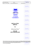
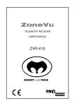
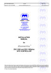
SERIES 2 MODULAR VIDEO MATRIX SYSTEM USERS MANUAL ZVM-SERIES 2 SECURITY with VISION Series 2 User Manual Issue 07 Page 2 of 30 CONTENTS 1. SERIES 2 MATRIX WELCOME 3 2. FEATURES 3 3. INSTALLATION 6 4. CONFIGURATION 8 5. USING A SITE CONTROLLER 18 6. DEFAULT CONFIGURATION 19 7. SPECIFICATIONS 20 8. TROUBLE SHOOTING GUIDE 23 9. DECLARATION OF CONFORMITY 24 10. MAINTENANCE 25 11. DISPOSAL 25 12. SUPPORT 26 13. WARRANTY 26 Whilst every effort has been made to confirm the information in this document is correct, MEYERTECH LIMITED cannot accept any liability for any errors, omissions and or incorrect information contained within this document. No part of this document may be reproduced or distributed in any form or by any means without prior written consent from MEYERTECH LIMITED. MEYERTECH LIMITED are committed to continuous product development and therefore reserve the right to change specifications without notice. 1997-2014 ALL RIGHTS RESERVED. MEYERTECH LIMITED Series 2 User Manual 1. Issue 06 Page 3 of 30 SERIES 2 MATRIX WELCOME Thank-you for purchasing one of our ZoneVu products. The ZVM SERIES 2 is a highly modular expandable video matrix system capable of routing over 1024 video inputs to over 256 video outputs. Designed with the latest video cross point technology the Bandwidth and Cross talk performance of the ZVM SERIES 2 Video Matrix is exceptional. The modular design brings flexibility and a wide choice of options for CCTV installations. MEYERTECH are dedicated to customer service and support. If you have any questions or problems, our staff will be pleased to assist you on the technical help line listed on page Error! Bookmark not defined.. Information regarding other MEYERTECH products and technical information can be found on the MEYERTECH World Wide Web site by pointing your Internet browser to: http://www.meyertech.co.uk 2. FEATURES ♦ Bridged video inputs ♦ Standard support for 32 operator keyboards (including a socket for direct attachment of 1 keyboard). ♦ OSD (camera captions & time/date generator) ♦ RS422 telemetry camera control ♦ Alarm Processing - optional ♦ PC Interfacing - optional ♦ High density cross point switching ♦ Non Volatile Memory ♦ 19-inch euro-rack enclosure compatible ♦ Compatible with leading UK GUI vendors ♦ Salvo & Zonal video switching ♦ Compatible with the full range of ZoneVu products. 2.1 OPTIONS A standard ZVM Series 2 configuration requires a ZVM-XXX video matrix module, a ZVC-256 and / or a ZSC-1000plus system controller module and a ZVS-PSU module. Optional modules can be added such as Alarm Processing and Management, and PC GUI control. A typical CCTV system installation may also require ZVR-xxx telemetry receivers, ZVK-xxx operator keyboards and ZVD-xxx peripheral equipment drivers. MEYERTECH LIMITED Series 2 User Manual Issue 07 Page 4 of 30 2.2 ZVM VIDEO MATRIX MODULES Typical ZVM Video Matrix Configuration 1 ZVM-9648 9U VIDEO INPUTS ZVM-9648 9U BRIDGED VIDEO INPUTS 96 BRIDGED VIDEO OUTPUTS 97 ZVM-9648 INPUT EXPANSION MODULE 6U VIDEO INPUTS 192 1 BRIDGED VIDEO OUTPUTS ZVM-9648 INPUT EXPANSION MODULE 6U BRIDGED VIDEO INPUTS VIDEO 48 OUTPUTS 49 VIDEO 96 OUTPUTS A typical ZoneVu ZVM Series 2 video matrix system will comprise of 3 or more system modules • ZVM-xxx Video Matrix Module • ZVC-256 and / or ZSC-1000plus System Controller • ZVS-PSU System Power Supply Unit MEYERTECH LIMITED Series 2 User Manual Issue 06 Page 5 of 30 ZVM Series 2 Modules are supplied in Euro rack enclosures and designed to fit into 19” Euro rack cabinets available from companies such as VERO. INSTALLATION 19 " 6u min ZVM-XXX 1u ZVC-256 / ZSC-1000-plus 1u ZVS-PSU MEYERTECH LIMITED Series 2 User Manual 3. Issue 07 Page 6 of 30 INSTALLATION To obtain the optimum performance from your ZVM SERIES 2 Video Matrix System please take time to read this manual before commencing installation. If you have any questions or problems our staff will be pleased to assist you on the technical help lines listed on page Error! Bookmark not defined.. WARNING THIS EQUIPMENT CONTAINS HAZARDOUS VOLTAGES. THIS EQUIPMENT MUST BE EARTHED TO PREVENT FIRE OR SHOCK HAZARD. DO NOT EXPOSE THIS EQUIPMENT TO RAIN OR MOISTURE. 3.1 CONNECTING THE ZVM SERIES 2 Connect up the ZVM SERIES 2 in accordance with the accompanying wiring diagram, paying special attention to the maximum ratings and the notes below. 1. The ZVM SERIES 2 MUST be earthed at the AC input supply terminal of the PSU. 2. ALWAYS use Screened cables for low voltage and signal cables ensuring that the screen is connected to 0V or Earth. 3. AVOID looming cables of differing characteristics together E.G. Video cables with cables carrying mains power. 4. The maximum cable run for Twisted Pair is typically 2Km. 5. The maximum cable run for VICTA is typically 750m. With ZSC-1000plus controller ZVD-XXX Peripheral Equipment Drivers ZVK-XXX Operator Keyboards Contact Alarm Cards ZVK Port PC1 / PC2 Port Victa Alarm Cards ZSC-1000plus Site Controller ZVR Ports ZVR-XXX Telemetry Receivers Video Inputs ZVM & ZVK Ports (Tx only) ZVM-XXX Video Switching Matrix MEYERTECH LIMITED Video Outputs Series 2 User Manual Issue 06 Page 7 of 30 6. Connect the ZVK port Tx pair at the ZSC-1000plus to the Matrix Control Rx pair at the ZVMXXX 7. Connect the ZVM port Tx pair to the OSD Text Rx pair at the ZVM-XXX. 8. Connect all Telemetry receivers to the ZVR Ports at the ZSC-1000plus 9. Connect all Keyboard Tx lines to the ZSC-1000plus ZVK port Rx line and all Keyboard Rx lines to the ZSC-1000plus ZVK port Tx lines. 10. Contact Alarm Sub-racks should be connected through the ZVK port. 11. Victa Alarm Communications from sub-racks or matrix cards should be connected to the Rx on the PC1 or PC2 ports at the ZSC-1000plus With ZVC-256 controller ZVD-XXX Peripheral Equipment Drivers ZVK-XXX Operator Keyboards ZSC-1000 or ZSC-1000plus Site Controller Keyboard Network Contact Alarm Cards Alarm Networks Victa Alarm Cards ZVC-256 Control Module Alarm Reporting Telemetry Control ZVR-XXX Telemetry Receivers Video Inputs Matrix & OSD Control ZVM-XXX Video Switching Matrix Video Outputs 6. Connect the ZVC-256 System Text Output to an unused video input. 7. Connect the Matrix Tx lines at the ZVC-256 to the Matrix Control Rx lines at the ZVM-XXX. 8. Connect the OSD Tx lines at the ZVC-256 to the OSD Text Rx lines at the ZVM-XXX. 9. Connect all Telemetry receivers to the Telemetry Tx lines at the ZVC-256. 10. Connect all Keyboard Tx lines to the ZVC-256 Keyboard Network Rx line and all Keyboard Rx lines to the ZVC-256 Keyboard Network Tx line. 11. Contact Alarm Sub-racks should be connected through the Alarm Network port. 12. Victa Alarm Communications from sub-racks or matrix cards should be connected to the Rx on the PC Alarms port. MEYERTECH LIMITED Series 2 User Manual 4. Issue 07 Page 8 of 30 CONFIGURATION The ZVM SERIES 2 is configured differently dependant on whether it has a ZVC-256 controller. For configuration without a ZVC-256, please refer to the ZSC-1000plus user manual. The ZVC-256 should now be configured by logging on from a ZVK-007 or ZVK-77 keyboard and following the On Screen Menus. Select the ZVC-256 System Text Output onto the desired monitor. 4.1 CONFIGURING A SERIES 2 WITH A ZVK-007 4.1.1 LOGGING ON FROM THE ZVK-007 KEYBOARD Access to Matrix Configuration is achieved by logging on to the SUPERVISOR LEVEL of the keyboard. 1. Log On to the ZVK-007 at Supervisor Level. 2. Use the MODE Key to step through the Menu options to ZVM CONFIG. Select using the ENT key. 3. The ZVM SERIES 2 will respond by displaying the Main Menu on the System Text Output. 4.1.2 MENU NAVIGATION The following ZVK-007 keys are used to configure the matrix. ENT Proceed to the selected option. Also used to accept parameters and to toggle through available options. DEL Used to navigate through the menus and to delete characters whilst editing text captions. MODE/SHIFT Toggle between Alphabetic and Numeric Keys. DEC Toggle between Upper and Lower case characters. << (PIP) Used to move cursor left when editing captions. >> (ACT) Used to move cursor right when editing captions. 4.2 CONFIGURING A SERIES 2 FROM A ZVK-77 Reference the ZVK-77 User Manual. Configuration is performed via the programming menu using the softkeys as indicated. MEYERTECH LIMITED Series 2 User Manual Issue 06 Page 9 of 30 4.3 OSD MENU SYSTEM Configuration is divided into three sections within the Main Menu of the On Screen Display. To navigate through the menu options press the DEL key. The highlighted option can then be accessed by pressing ENT. MAIN MENU Setup Matrix Setup Time/Date Load Defaults Return To Operation 4.4 SETUP MATRIX The SETUP MATRIX menu is used to configure Camera’s, Monitor’s, Sequencing, Alarm’s and other features. SETUP MATRIX MENU Cameras Monitors Sequencing Alarms * Miscellaneous Return To Main Menu * ZVA-APM Option required. MEYERTECH LIMITED Series 2 User Manual Issue 07 Page 10 of 30 4.4.1 CAMERA OPTIONS CAMERA OPTIONS MENU Camera [ 01 ] Camera Text Timeouts OSD [ ON ] Return To Sub Menu The CAMERA OPTIONS MENU allows the user to configure all options on a camera by camera basis. To view the current settings for a camera enter the camera number in the camera field. All other fields on the page will then be updated with the current operating values. Editable Fields are: Camera [ ] Enter a camera number between 01 and 256. Camera Text Allows the user to enter a caption for the current camera of up to 24 characters in length. OSD [ Dynamic OSD. OSD is displayed on a monitor by monitor basis. However, when feedback of video signals back into the matrix is required it is possible to switch OSD off on a camera by camera basis by setting the OSD field to OFF. ] 4.4.1.1 Timeouts TIMEOUTS Park Timeout [ OFF ] Preset [ 0 ] Time Min [ 10 ] Lamp Timeout [ OFF ] Time Min [ 10 ] Iris Timeout [ OFF ] Time Min [ 10 ] Return To Sub Menu The TIMEOUTS MENU allows the user to configure all automatic time-out options for the camera selected. MEYERTECH LIMITED Series 2 User Manual Park Timeout [ Preset [ ] Issue 06 Page 11 of 30 Toggle camera auto park facility ON or OFF. ] Preset allocated to each camera used with auto park facility 0 - 16 . Time (Min) [ ] Time before camera is automatically sent to the auto park preset. Lamp Timeout [ Time (Min) [ ] Iris Timeout [ Time (Min) [ ] Toggle camera lamp auto time-out facility ON or OFF. Time before cameras lamp is automatically switched off. ] Toggle camera iris auto time-out facility ON or OFF. ] Time before camera iris is automatically returned to the auto iris. Lamp and Iris time-outs can be overridden from a ZVK-007 keyboard. 4.4.2 MONITOR OPTIONS MONITOR OPTIONS MENU Monitor [ 1 ] Text [ TDG ] Text Position [ TOP ] Text Colour [WHITE ] Apply globally [ NO ] Return To Sub Menu The MONITOR OPTIONS MENU allows the user to configure all options available on a monitor by monitor basis. Editable Fields are: Monitor [ ] Enter a Monitor number between 1 and 8. Text [ ] Text Position[ Allows the user to define whether Camera Caption and/or Time/Date are displayed. ] Toggle monitor text position TOP or BOT. Text Colour [ ] Toggle monitor text colour BLACK or WHITE. Apply globally [ ] If set to YES this monitor configuration will be applied to all monitors. MEYERTECH LIMITED Series 2 User Manual Issue 07 Page 12 of 30 4.4.3 SEQUENCING OPTIONS SEQUENCING MENU Pattern [ 1 ] Position [ 1 ] Camera [ 1 ] Max Positions [ 32 ] Dwell Time [60] Return To Sub Menu The SEQUENCING MENU allows the user to configure all monitor sequencing options. A pattern is a defined list of cameras. Each camera is switched to the sequencing monitor in turn followed by a dwell time before the next SALVO. The term SALVO indicates that all sequencing monitors are updated simultaneously i.e. they each display the next camera in the sequence at the same time. To view the current settings for a pattern, enter the pattern number in the pattern field. All other fields on the page (except for Dwell Time, which is a global setting,) will then be updated with the current operating values. Editable Fields are: Pattern [ ] Enter a pattern number between 1 and 8. Each pattern can hold up to 32 Cameras. Position [ ] Indicates the current position in the current pattern which is to be edited. Range 1-32. Camera [ ] Allows the user to enter the camera to be sequenced in the pattern number and position number indicated by the pattern and position fields. Max Positions [ Dwell Time [ ] ] Up to 32 positions can be programmed into any pattern. The Max Position field sets the position after which the sequence restarts at position 1. The global time between updating monitors and stepping to the next pattern position. Range 1 to 99 seconds. MEYERTECH LIMITED Series 2 User Manual Issue 06 Page 13 of 30 4.4.4 MISCELLANEOUS OPTIONS MISCELLANEOUS MENU Keyboards [ 8 ] Polling mode [ Plus ] AUX Function [Scene] Return To Sub Menu The number of keyboards, which the ZVC-256 controller polls, can be set from within the MISCELLANEOUS MENU. • The maximum number of keyboards is 32. If fewer keyboards are connected, it is advised that this menu reflect the actual number of keyboards connected to the system. • The polling mode is the method by which the Series 2 attempts to communicate with the operator keyboards. This should only be modified after consultation with Meyertech Technical Support. The options are ‘Plus’ and ‘Norm’ • The functionality of the AUX key can also be set-up. This allows the AUX key on the keyboard or the ZoneVu Mosaic GUI, to double up. There are two options, AUX or Scene. The first leaves the AUX function unchanged, the second sets it up to change scenes. This means that if you have cameras capable of storing scene information, the AUX key can now be used to switch through them in sequence. 4.5 ALARM OPTIONS ALARM OPTIONS MENU Victa Alarms Contact Alarms Alarm Monitors Alarm Management Return To Sub Menu The ZVA-APM alarm module can process up to 480 contact alarms or a combination of 32 contact alarms and 96 VICTA (video) alarms. MEYERTECH LIMITED Series 2 User Manual Issue 07 Page 14 of 30 4.5.1 VICTA ALARMS VICTA ALARMS MENU Camera [ 1 ] Alarm [ TAMP ] Enabled [ ON ] Rpt Kbd [ 1 ] Event # 1 Event # 2 Return To Sub Menu The VICTA ALARMS MENU allows the user to configure all options relating to alarms received from ZoneVu receivers. To view the current settings for a camera enter the camera number in the Camera field. Options Available are: Camera No [ Alarm [ ] Enabled[ ] Enter a camera number between 01 and 256. Toggle through the 8 alarms. There are 6 contact alarms 1 tamper and 1 sync fail alarm per receiver ] Enable or Disable individual alarms on each camera. Rpt Kbd[ ] The keyboard to which alarms on this camera are reported. 0 = OFF. Events Each Victa Alarm can trigger two events. Each event can be configured to switch a Camera to a Monitor and send a Camera to a Preset. Additionally, individual aspects of each event can be switched ON or OFF. Alarm monitors for each event are configurable from the Alarm Monitors menu. EVENT #1 Camera [ 1 ] Preset [ 8 ] Send Cam to Preset [ ON ] Switch to Monitor [ ON ] Return To Sub Menu MEYERTECH LIMITED Series 2 User Manual Issue 06 Page 15 of 30 4.5.2 CONTACT ALARMS CONTACT ALARMS MENU Contact [ 1 ] Enabled [ ON] Status [ N.O. ] Rpt Kbd[ 1 ] Event #1 Event #2 Event #3 Return To Sub Menu The CONTACT ALARMS MENU allows the user to configure all options relating to alarms received from ZoneVu ZVA-032 alarm cards. A ZVA-AIR Alarm Sub-rack can contain up to 15 ZVA-032 cards giving a maximum of 480 contact alarms. To view the current settings for a contact enter the contact number in the Contact field. Options Available are: Contact [ ] Enter a camera number between 01 and 480. Enabled [ ] Enable or Disable individual contact alarms ON or OFF Status [ Configures individual alarms as Normally Open (NO) or Normally Closed. ] Rpt Kbd[ ] The keyboard to which the alarm selected are reported. 0 = OFF. Events Each Contact Alarm can trigger three events. Each event can be configured to switch a Camera to a Monitor and send a Camera to a Preset. Additionally, individual aspects of each event can be switched ON or OFF. Alarm monitors for each event are configurable from the Alarm Monitors menu. 4.5.3 ALARM MONITORS ALARM MONIORS MENU Monitor 1 [ 1 ] Monitor 2 [ 2 ] Monitor 3 [ 3 ] Return To Sub Menu MEYERTECH LIMITED Series 2 User Manual Issue 07 Page 16 of 30 The ALARM MONITORS MENU allows the user to configure the monitors to which cameras are switched when events are triggered. Monitor 1 corresponds to an Event 1 camera switch, Monitor 2 corresponds to an Event 2 camera switch and Monitor 3 corresponds to an Event 3 camera switch,. When no alarm conditions exist, all alarm monitors automatically switch to display blank screens. 4.5.4 ALARM MANAGEMENT ALARM MANAGEMENT Alarm Handling [ Events ] Return To Sub Menu Its is possible to configure the alarm processing module to handle incoming alarms in one of two ways. Events When an alarm occurs and the alarm queue is not yet full, the alarm processor immediately sends cameras to presets as determined by the user defined configuration data. When an alarm progresses and reaches the top of the alarm queue the alarm processor switches cameras to monitors and reports to the report keyboard as determined by the user defined configuration data. Alarms are cancelled from a ZVK-xxx keyboard. If an alarm is cancelled, but is still active, the alarm re-enters the queue at the bottom. PC Rpt No user defined events are acted upon. Alarms are reported directly to a PC via the PC Alarms port. Protocol available on request. MEYERTECH LIMITED Series 2 User Manual Issue 06 Page 17 of 30 4.6 SETUP TIME/DATE TIME DATE MENU Set Hours Set Minutes Set Day Set Month Set Year [ 17 ] [ 00 ] [ 06 ] [ 11 ] [ 96 ] Initialize Clock Return To Main Menu The TIME DATE MENU allows the user to set and initialize the real time clock. The clock display is updated once per second. The options for time and date are set on a monitor by monitor basis within the MONITOR OPTIONS MENU. Each field must be set individually and the real time clock will only take on the new values when Initialize clock is selected. 4.7 LOAD DEFAULTS This option allows the user to reload all default programmable information, such as camera captions, text options sequences. See section DEFAULT CONFIGURATION for default data. The user is given the option to abort loading default data if necessary. MEYERTECH LIMITED Series 2 User Manual 5. Issue 07 Page 18 of 30 USING A SITE CONTROLLER The Series 2 matrix with ZVC-256 controller can be used in conjunction with a Meyertech Site Controller product. rd The site controller takes over responsibility for communicating with keyboards, receivers and 3 party devices allowing the Series 2 to concentrate on being a video matrix. If the Series 2 is purchased with a site controller and ZVC-256 controller then the alarm menu is disabled and all alarms are automatically reported to the site controller. Additionally the miscellaneous menu has different options: MISCELLANEOUS MENU MAC address [ 8 ] Polled mode [ On ] Return To Sub Menu • MAC address This is the address that the Series 2 will respond to polls from the site controller. • Polled mode This determines how the Series 2 communicates with the site controller. o Set to On if connected to a polling network (e.g. ZVK or ZoneVu port) o Set to Off if connected point-to-point to a non-polling port (e.g. ZVM port) For more information on operating a Series 2 with a site controller see the Site Controller User Manual. MEYERTECH LIMITED Series 2 User Manual 6. Issue 06 Page 19 of 30 DEFAULT CONFIGURATION Default Configurations as a result of Load Defaults or factory preset conditions. Camera Camera Captions Park Time-out Preset Time (Mins) Lamp Time-out Time (Mins) Iris Time-out Time (Mins) OSD PRESENT Camera 01 OFF [ 0 ] (HOME) [ 10 ] OFF [ 10 ] OFF [ 10 ] ON By Monitor Monitor Text Text Position Text Colour ON TDG & CAPTION TOP WHITE By Sequence Pattern Position # Last Position Camera # 32 By Victa Alarm Alarm Inputs ON By Contact Alarm Enabled Status ON Normally Open By Alarm Event Camera Preset Camera to Monitor Camera to Preset Report to Keyboard Keyboard Number 1 0 ON ON ON 1 Global Time Date Dwell Time Alarm Monitors Alarm Handling Aux. Function 23:59:00 31:12:99 60 seconds60 seconds 1, 2, 3 Events Aux By Camera MEYERTECH LIMITED to Camera 256 Series 2 User Manual 7. Issue 07 SPECIFICATIONS 7.1 ELECTRICAL POWER INPUT - +12VDC & -12VDC from ZVS-PSU POWER CONSUMPTION - Less than 80W per 48 outputs VIDEO - Inputs 1V pk-pk 75Ω - Outputs 1V pk-pk 75Ω CROSSTALK - Better than 50dB SIGNAL TO NOISE - Better than 50dB 7.2 PHYSICAL 7.2.1 ZVC-256 MEYERTECH LIMITED Page 20 of 30 Series 2 User Manual Issue 06 Page 21 of 30 Pin Connections relative to the ZVC-256 controller Matrix & OSD Keyboard Network Eng. Key. Telemetry Network Alarms Network Alarms PC Port Control PC Port Standard RS422 RS422 RS422 RS422 RS422 RS232 RS232 1 -Tx -Rx -Rx -Tx -Rx N.C. N.C. 2 +Tx +Rx +Rx +Tx +Rx Rx Rx 3 -Tx -Tx -Tx -Tx -Tx Tx Tx 4 +Tx +Tx +Tx +Tx +Tx N.C. N.C. 5 N.C. N.C. 5V 0V 0V 0V 0V 6 N.C. N.C. 0V -Tx N.C. N.C. N.C. 7 N.C. N.C. N/A +Tx N.C. N.C. N.C. 8 N.C. N.C. N/A -Rx N.C. N.C. N.C. 9 N.C. N.C. N/A +Rx N.C. N.C. N.C. Pin Connections relative to the ZSC-1000+ controller ZVM Port ZVK Port PC1 / PC2 Port Standard RS422 RS422 RS232 ZVM-XXX Matrix OSD Matrix Control Alarms 1 N.C. N.C. N.C. 2 N.C. N.C. Rx 3 0V 0V N.C. 4 -Tx -Tx N.C. 5 +Tx +Tx 0V 6 N.C. N.C. N.C. Pin Connections relative to the ZVM-XXX Video Matrix Matrix Control Matrix OSD Alarms Standard RS422 RS422 RS232 1 -Rx 2 +Rx 3 4 -Rx +Rx 7.2.2 ZVM-XXX MEYERTECH LIMITED 5 0V 0V 6 7 Tx 0V 8 N.C. N.C. N.C. 9 N.C. N.C. N.C. Series 2 User Manual Issue 07 Page 22 of 30 TEMPERATURE - Operational 0 Degrees to 40 Degrees C Storage minus 20 Degrees to plus 60 Degrees C Humidity 10% to 95% (Non-condensing) VIDEO INPUTS - BNC Terminal with link for 75Ω termination (remove if bridging input). VIDEO OUTPUTS - BNC Terminal ENG KEYBOARD - FCC socket RJ-11 COMMS - RS422 twisted pair (Telemetry / Network Communications) RS232 twisted pair (PC Control / PC Alarms ) ZoneVu commands and data are transmitted in PACKETS. Each Packet has a unique HEADER to identify its destination and a common TERMINATOR to identify the end of the data Packet. The Packet Headers and the Packet Terminator are formed from nonprintable ASCII characters. Commands and data are formed from printable ASCII characters. ASCII NUL characters are used to separate data fields. Baud rate (OSD) Baud rate (Other) - 19200 baud 9600 baud Parity - none Stop bits - 1 Flow control - none Data bits - 8 MEYERTECH LIMITED Series 2 User Manual 8. Issue 06 Page 23 of 30 TROUBLE SHOOTING GUIDE This Trouble Shooting Guide should be used in the first instance of encountering any problems with the ZVM SERIES 2. If problems persist, contact MEYERTECH on the Technical Help line numbers given on page Error! Bookmark not defined.. Symptom Keyboard displays “Comms. Fault” Solution Ensure that the Keyboard MAC number is less than the number of keyboards declared. Check that the keyboard MAC number does not clash with another keyboard MAC number. Especially after installation of keyboard software updates. Verify that the Series 2 is not operating in Site Controller Mode. MEYERTECH LIMITED Series 2 User Manual 9. Issue 07 Page 24 of 30 DECLARATION OF CONFORMITY EC DECLARATION OF CONFORMITY ACCORDING TO ARTICLE 10 OF COUNCIL DIRECTIVE 89/336/EEC Manufacture’s Name: MEYERTECH LIMITED Manufacture’s Address: MEYERTECH Limited Zebra Court White Moss View Greenside Way Manchester M24 1UN declares, that the product(s): Product Name : ZVM SERIES 2 Video Matrix Model(s) : All Product Options: All conforms to the following Product Specifications : EN55022 EN50093 CLASS B Supplementary Information: MEYERTECH declare under our sole responsibility that the product to which this declaration relates, is in conformity with the protection requirements of council directive 89/336/EEC on the approximation of the laws of the member states relating to electromagnetic compatibility, when installed in accordance with the instructions given in this manual. SIGNED - S K MEYERS Director MEYERTECH LIMITED ISSUED THIS DAY 1st January 1997 European Contact: Meyertech Limited (Head Office), Zebra Court, White Moss View, Greenside Way, Manchester, England, M24 1UN. MEYERTECH LIMITED Series 2 User Manual 10. Issue 06 Page 25 of 30 MAINTENANCE The Series 2 requires no Planned Preventive Maintenance periods (PPM’s) as it is mainly solid state in design. The Series 2 contains no serviceable parts and should be returned to our Service Centre in Scunthorpe for repair or replacement under warranty. Any repairs, attempted repairs or replaced components not carried out by the Meyertech Service Centre will void all Meyertech warranties and liabilities. If your Series 2 has to be returned to our Service Centre please follow the returns procedure below, otherwise delays may be incurred in returning or replacing the Series 2. 11. DISPOSAL There are no additional requirements beyond safe working practice in the decommissioning of the Meyertech Series 2. However the Series 2 contains printed circuit boards populated with electronic components. The whole unit must be returned to Meyertech Service Centre for final disposal. Please follow the normal returns procedure. MEYERTECH LIMITED Series 2 User Manual Issue 07 Page 26 of 30 Meyertech Limited is a member of the CCTV User Group. 12. SUPPORT At Meyertech our staff understand quality support is important to you, vital in fact, which is why we place such a high precedence on providing it. For all matters relating to support go to our website to find the information your require visit http://www.meyertech.co.uk/support.html WARRANTY Please refer to Meyertech Limited ‘Terms & Conditions of Sale of Goods & Services’ for interpretation. 1. If the Buyer establishes to the Seller's reasonable satisfaction that there is a defect in the materials or workmanship of the Goods manufactured, then the Seller shall at its option, at its sole discretion and within a reasonable time, a. arrange for the repair or making good such defect or failure in such Goods free of charge to the Buyer (including all costs of transportation of any Goods or materials to and from the Buyer for that purpose), b. replace such Goods with Goods which are in all respects in accordance with the Contract, or subject, in every case, to the remaining provisions of this Condition 1 provided that the liability of the Seller under this Condition 1 shall in no event exceed the purchase price of such Goods and performance of anyone of the above options shall constitute an entire discharge of the Seller's liability under this warranty. 2. Condition 1 shall not apply unless the Buyer: a. notifies the Seller in writing of the alleged defect within 12 (twelve) months from delivery or such other period or periods as may be agreed in writing between the Seller and the Buyer, and b. allows the Seller a reasonable opportunity to inspect the relevant Goods. 3. For the avoidance of doubt, the Seller shall be under no liability under the warranty in Condition 1 above: a. where such defects arise from any drawing, design or specification supplied by the Buyer; or MEYERTECH LIMITED 1.1.1.1.1 ZVR-530 13. Series 2 User Manual Issue 06 Page 27 of 30 b. where such defects arise from fair wear and tear, wilful damage, or negligence of a party other than the Seller (or its employees or authorised personnel), abnormal working conditions, failure to follow the Seller's instructions (whether oral or in writing), misuse or alteration or repair of the Goods without the Seller's approval; or c. where such defects arise in parts, materials or equipment which have not been manufactured or designed by the Seller but have been purchased at the Buyer's request by the Seller from the Buyer's designer and manufacturer or from some other third party (the “Third Party Supplier”). d. if the total price of the Goods has not been paid by the due date for payment e. in respect of any type of defect, damage or wear specifically excluded by the Seller by notice in writing: or f. if the Buyer makes any further use of the Goods after giving notice in accordance with Clause 1 4. Any repaired or replaced Goods shall be redelivered to the Buyer free of charge to the original point of delivery but otherwise in accordance with and subject to these Conditions. 5. Alternatively to Condition 1 the Seller shall be entitled at its absolute discretion on return of the defective Goods to the Seller (at the Seller's request) to refund the price of the defective Goods in the event that such price shall already have been paid by the Buyer to the Seller, or, if such price has not been paid, to relieve the Buyer of all obligation to pay the sum by the issue of a credit note in favour of the Buyer in the amount of such price. 6. In respect of all Goods supplied to the Seller by a Third Party Supplier the Seller will on request pass on to the Buyer (in so far as reasonably possible) the benefit of any warranty given to the Seller by such Third Party Supplier and will (on request) supply to the Buyer details of the terms and conditions of such warranty and copies of any relevant product information sheets, technical data sheets or product leaflets issued by such Third Party Supplier and the Buyer shall be solely responsible to the entire exclusion of the Seller for complying with the same. 7. For the purposes of Condition 1 references to Goods shall be deemed to exclude software. 8. The Buyer acknowledges that software in general is not error-free and agrees that the existence of such errors in the Software Programs shall not constitute a breach of this Contract. 9. In the event that the Buyer discovers a material error which results in the Programmed Products not performing substantially in accordance with the Functional Specification, or the Licensed Programs not performing substantially in accordance with the relevant Program Documentation and notifies the Seller of the error within 90 days from the date of the Seller making available the respective software to the Buyer (the `warranty period") the Seller shall at its sole option either refund the price which the Buyer has paid to the Seller (or if such price has not been paid, relieve the Buyer of all obligations to pay the sum) in respect of the respective software or use all reasonable endeavours to correct by patch or new release (at its option) that part of the software which does not so comply provided that such non-compliance has not been caused by any modification, variation or addition to the software not performed by the Seller or caused by its incorrect use, abuse or corruption of the software by use of the software with other software or on equipment with which it is incompatible, 10. To the extent permitted by English law, the Seller disclaims all other warranties, with respect to the software which it provides pursuant to the Contract, either express or implied, including but not limited to any implied warranties of satisfactory quality or fitness for any particular purpose. 11. The Buyer is solely responsible for various scanning the software that it receives from the Seller pursuant to the Contract. 12. The Seller warrants that it will use reasonable skill and care in providing the Services to the buyer MEYERTECH LIMITED Series 2 User Manual Issue 07 MEYERTECH LIMITED Page 28 of 30 Series 2 User Manual Issue 06 NOTES MEYERTECH LIMITED Page 29 of 30 Series 2 User Manual Issue 07 NOTES MEYERTECH LIMITED Page 30 of 30