1
Aviation Human Factors Division
Institute of Aviation
AHFD
University of Illinois
at Urbana-Champaign
1 Airport Road
Savoy, Illinois 61874
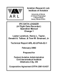
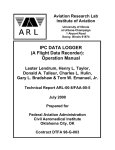
IPC DATA LOGGER
(A Flight Data Recorder):
Operation Manual
Change 2
Lester Lendrum, Henry L. Taylor,
Donald A. Talleur, & Tom W. Emanuel, Jr.
Technical Report AHFD-03-8/FAA-03-2
March 2003
Prepared for
Federal Aviation Administration
Civil Aeromedical Institute
Oklahoma City, OK
Cooperative Agreement DTFA 2001-G-037
Forward
To
Change 2
Change 2 to the Technical Reports ARL-02-2/FAA-02-1, February 2002 titled IPC DATA LOGGER (A
Flight Data Recorder): Operation Manual, Change 1 and ARL-00-8/FAA-00-5, July 2000 titled IPC
DATA LOGGER (A Flight Data Recorder): Operation Manual has been prompted by the necessity to
replace the vertical gyroscopes due to anticipated (and experienced) end-of -service limits. The mechanical
gyroscope of the original design has been replaced by a solid-state gyroscope system. The new system has
a claimed MTBF (Mean Time Between Failure) of 50,000 hours. This document incorporates the changes
made to the hardware of the IPC Data Logger, the changes in power-converter requirements, and some
minor software changes unrelated to the normal operation of the system but useful in verifying the
replacement hardware. Figure 1 has be changed to reflect the hardware modifications.
Forward
To
Change 1
Change 1 to the Technical Report ARL-00-8/FAA-00-5, July 2000 titled IPC DATA LOGGER (A Flight
Data Recorder): Operation Manual has been prompted by two developments. First and most important, the
source of the GPS differential corrections used in the original Data Logger has been lost with the departure
of Differential Corrections, Inc. It has been necessary to establish a substitute source for differential
correction data. Second, since the DOD has discontinued “selective availability,” autonomous GPS position
accuracy is marginally sufficient for the design purposes allowing the original restriction, of not allowing
data logging unless differential corrections were available, to be relaxed. This document includes the
changes made to the software, hardware, and operational modes of the IPC Data Logger. The present
system now uses the Wide Area Augmentation System (WAAS) for differential corrections.
i
The page intentional left blank
ii
Table of Contents
1.
INTRODUCTION ................................................................................................................................ 1
2.
COMPONENTS ................................................................................................................................... 1
SINGLE BOARD COMPUTER ......................................................................................................................... 2
DIGITAL STORAGE DEVICES ........................................................................................................................ 3
SERIAL DATA PORTS ................................................................................................................................... 3
ANALOG TO DIGITAL CONVERTER .............................................................................................................. 4
VERTICAL GYROSCOPE ............................................................................................................................... 4
PENDULUM .................................................................................................................................................. 5
COMPASS SYSTEM ....................................................................................................................................... 5
POSITIONING SYSTEM.................................................................................................................................. 6
GPS Receiver System.............................................................................................................................. 6
Wide Area Augmentation System............................................................................................................ 6
RADIO-NAVIGATION INSTRUMENTS ............................................................................................................ 7
AIRSPEED SENSOR ....................................................................................................................................... 7
USER DISPLAY/CONTROL CONSOLE ............................................................................................................ 7
POWER CONVERTER .................................................................................................................................... 9
3.
SOFTWARE ......................................................................................................................................... 9
SYSTEM OPERATING SOFTWARE ................................................................................................................. 9
POST FLIGHT DATA CONVERSION SOFTWARE ........................................................................................... 10
4.
OPERATION...................................................................................................................................... 11
GENERAL OPERATIONAL PROCEDURES ..................................................................................................... 11
OPERATIONAL ERROR CODES ................................................................................................................... 12
STRUCTURE AND CONTENT OF DATA FILES .............................................................................................. 13
POST PROCESSING PROCEDURES ............................................................................................................... 15
5.
MAINTENANCE AND TROUBLESHOOTING............................................................................ 16
GENERAL SYSTEM SOFTWARE CONFIGURATION ....................................................................................... 16
System Start Up .................................................................................................................................... 16
Logger Parameter File ......................................................................................................................... 16
GENERAL MAINTENANCE AND CALIBRATION ........................................................................................... 17
Periodic Maintenance .......................................................................................................................... 17
Calibration ........................................................................................................................................... 17
TROUBLESHOOTING .................................................................................................................................. 17
General Computer Problems................................................................................................................ 17
Compass System Problems ................................................................................................................... 18
GPS System Problems .......................................................................................................................... 19
USE IN 24-VOLT AIRCRAFT ....................................................................................................................... 22
ACKNOWLEDGMENTS AND DISCLAIMER ..................................................................................... 22
REFERENCES ........................................................................................................................................... 23
HARDWARE AND SOFTWARE REFERENCE MANUALS .............................................................. 23
APPENDICES ............................................................................................................................................ 24
APPENDIX 1 – BIOS SETTINGS FOR SINGLE BOARD COMPUTER ............................................................... 24
APPENDIX 2 – CONFIGURATION OF THIRD SERIAL DATA PORT ................................................................ 24
APPENDIX 3 – CONFIGURATION OF THE KVH COMPASS SYSTEM ............................................................. 25
iii
APPENDIX 4 – CONFIGURATION OF THE A/D SYSTEM ............................................................................... 25
AD12-8 ................................................................................................................................................. 25
AT16-P.................................................................................................................................................. 26
APPENDIX 5 – ASHTECH WAAS SOFTWARE COMMANDS......................................................................... 26
APPENDIX 6 – INITIAL SETTINGS FOR DISPLAY/CONTROL CONSOLE ........................................................ 27
APPENDIX 7 – SOURCE CODE .................................................................................................................... 28
System Operation Software .................................................................................................................. 28
Basic Post Flight Software ................................................................................................................... 69
UTM Post Flight Software.................................................................................................................... 72
iv
1. Introduction
The IPC Data Logger (a flight data recorder) is designed to support research involving pilot performance in
executing instrument flight procedures. The system is designed for use in small single engine aircraft and
can easily be removed to return the aircraft to normal service. The system is based on a commercial single
board computer, recording data at the rate of one frame per second. In addition to aircraft position and
altitude, pitch, roll, yaw, magnetic heading, vertical speed, and airspeed are recorded. The radio-navigation
displays (Very-high-frequency Omni Range/LOCalizer (VOR/LOC) and Glideslope) are also recorded.
Provision is made for the check pilot/operator to mark sections of the flight records to aid in the subsequent
analysis of the data. Apart from connection to the pitot/static system and the navigation displays,
instruments internal to the Data Logger generate all data.
The data logger is housed in an aluminum enclosure 22 inches in width, 24 inches in length, and
approximately 12 inches in height. The weight is approximately 40 pounds. To install the IPC Data Logger
in the aircraft (Beech Sundowner C-23, in this application), the rear seats were removed and the logger
mounted in their place; a custom floor plate to which the Data Logger is mounted replaced the original
floor of the rear seating and baggage area. A flux-gate magnetic compass system is mounted in a separate
non-magnetic enclosure so as to allow its positioning within the airframe in order to provide the most
accurate heading information possible.
Wiring of the aircraft has been modified to supply 12-volt DC power and to provide the data from the
aircraft’s VOR/LOC’s and Glideslope systems to the Data Logger. An FAA/PMA approved GPS antenna
was installed on the fuselage above the front seating area. This is the only available horizontal area with an
unobstructed view of the sky. The pitot and static air systems were modified to provide for connection to
the data logger for measurement of airspeed.
These modifications were field approved by the local Flight Service District Office (FSDO). A test flight
was required by the FAA to demonstrate the data logger did not adversely effect the operation of critical
aircraft systems. FAA Form 337 (Major Repair or Alteration) was submitted to document these
modifications.
The Data Logger may be adapted to aircraft other than the Beech Sundowner. Some component changes
and wiring modifications would be required to operate the system in an aircraft that is equipped with a 24
volt DC power system. Re-calibration of the airspeed may be required to accommodate a different pitotstatic system.
The interface to the radio-navigation systems (VOR/LOC and GS) was designed for the Bendix/King KI2xx system of outputs; wiring modifications within the Data Logger may be required if other navigation
radios are employed.
2. Components
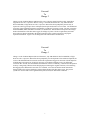
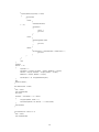
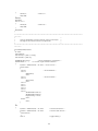
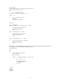
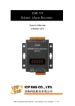
All the components of the Data Logger System are houses in a single enclosure with the exception of the
Compass System and User Display/Control Console. The locations of the major components are illustrated
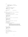
in the Figure below.
1
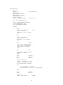
Figure 1: Component Layout
Airspeed
Sensor
Analog
Multiplexer
Microcomputer
and Card Cage
Solid State Gyroscope
and Pendulum
DC-to DC Power
Converter
GPS
Receiver
Single Board Computer
The central component of the Data Logger is the single board computer. This unit is essentially an IBM PC
compatible computer that is fabricated on a single Industry-Standard- Architecture (ISA) board yet is
capable of operation in a greater range of environmental conditions than a standard desktop personal
computer. The Industrial Computer Source Model SB486PV single board computer is designed around an
Intel 486DX100 microprocessor and provides support for keyboard control, video adapter, both fixed and
floppy disks, two serial ports, and one parallel port. The Intel 486DX100 has a built-in numeric coprocessor, which would not normally be needed since no extensive floating-point mathematical calculations
are required in the operation of the Data Logger. However, the present compilation of the software
assumes such a co-processor is present. The keyboard and video adapter/display are used only during
development and repair/maintenance functions. A rugged card cage/passive motherboard is used to house
the SB486PV, an additional serial port interface, and an analog-to-digital converter. There are at least two
additional ISA slots available for additional hardware if required for additions to the present configuration.
2
The disk operating system is MSDOS 6.22 and is completely standard. The system is capable of operating
as a normal personal computer with no modification except for changes to the autoexec.bat file, which is
designed to start the data logger software automatically following the load of the MSDOS operating system
when the system is powered.
There are a number of settings in the BIOS of the SB486PV single board computer that have been modified
from the standard configuration to facilitate the operation of the Data Logger. These are documented in
Appendix 1.
Digital Storage Devices
The system is equipped with a 3 Gigabyte IDE fixed disk that contains the MSDOS operating system, the
data logger software, and provides primary storage for the recorded flight data files.
A 3½” floppy disk drive is also provided to permit a convenient method of updating the software and to
off-load the Data Logger data files at the end of each logging session. The Data Logger will not attempt to
load an operating system from the floppy drive and depends completely on the fixed disk for operation.
Serial Data Ports
Two serial data ports (RS-232) are the standard hardware provided on the SB486PV single board computer.
These are configured in the industry-standard manner as COM1 (I/O Ports 3F8-3FF, IRQ 4) and COM2
(I/O Ports 2F8-2FF, IRQ 3).
A third serial port is required for data logger operations. A SIIG I/O Professional multifunction
input/output board, Model IO1809, provides this capability. This board has two additional serial ports and
one additional parallel port. In this application, only one serial port is used and the remaining serial port
and the parallel port are disabled. The serial port on the SIIG board is configured in a non-standard manner
since all serial input/output in the data logger uses interrupt driven routines and each serial port must have a
unique IRQ (hardware interrupt request) channel. This port is designated COM3 (I/O Ports 2E8-2EF, IRQ
5). The hardware configuration of this board is documented in Appendix 2.
COM1 communicates with the Global Positioning receiver; COM2 with the User Display/Control Console,
and COM3 with the KVH Compass System.
All serial ports initially operate at 9600-baud, no parity, 8-bit of data with 1 stop bit (9600N81). The GPS
port (COM1) is operated at 38,400 baud after the GPS receiver is initialized.
3
Analog to Digital Converter
An analog-to-digital converter allows the recording of the following analog variables in digital format.
•
•
•
•
Aircraft pitch and roll data from the Vertical Gyroscope
Aircraft yaw data from the Pendulum
Airspeed data, derived from a differential pressure sensor
Electronic Navigation data from VOR, LOC, Glideslope
In total, there are twelve channels of analog information that are sampled and converted into digital data in
this application. It is possible to add significant number of additional analog sensors to the system, up to
128-channels. The magnitude of the variables to be measured range from a few tenths of a volt full scale to
10 volts full scale. Additionally, some variables are referenced to ground potential while others are the
difference between two voltages (differential).
In order to accommodate the range and types of signal voltages, an analog-to-digital converter plus a 16channel analog multiplexer are employed. The analog-to-digital converter is a Model AD12-8
manufactured Industrial Computer Source, the multiplexer is Model AT16-P by the same manufacturer.
The hardware configuration of these boards is documented in Appendix 4.
The basic analog-to-digital converter used is capable of 12-bit resolution: one part in 4096. The
combination of the AD12-8 and AT16-P allow up to sixteen channels of both single-ended and differential
inputs with the gain (amplification) of each channel individually selected under control of the software.
The A/D system incorporates a counter/timer system that is used to automatically sequence through all of
the active channels once given the command to begin the analog-to-digital conversion. Hardware interrupts
are used to determine when each conversion is complete. A number of sequential conversions are averaged
to determine the final value to be recorded for each of the variables measured.
A precision + 10 volt DC reference voltage output is provided by the AD12-8 to excite those sensors which
require such an external source (the vertical gyroscope, pendulum, and airspeed sensor).
Vertical Gyroscope
A solid-state vertical gyroscope is employed to provide aircraft pitch and roll information for the Data
Logger. The component used is the Model VG400CC manufactured by Crossbow Technology, Inc. The
intialization time is less than 1 minute. The unit weighs 0.3 pounds and requires 0.4 amps running current
at 9-30 volts DC. The operational limits are ± 90 degrees of pitch; the roll axis is continuous (360 degrees).
The unit is mounted in a specially fabricated carrier (which also is used to mount the Pendulum system
described below) and this carrier is further isolated from the Data Logger enclosure by Lord mounts.
The outputs are provided by two digital-to-analog convertors. The signal is nominally 22.8 millivolts per
degree in the roll axis and 45.5 millivolts per degree in the pitch axis. Both axes are calibrated initially on
the bench at 0 degrees and ± 45 degrees. Flight tests are performed to verify that the recorded data
accurately represents the data provided to the pilot by the standard aircraft instruments.
4
Pendulum
A standard pendulum is employed to sense aircraft yaw in the same manner as the ball of a rate-of-turn
indicator. The instrument used is the Model CP17-0601-1 produced by Humphrey, Inc. This is a passive
instrument with a range of ± 45 degrees and a weight of 6 ounces.
Output is by means of a center-tapped potentiometer excited by the 10 volt DC source supplied from the
analog-to-digital convertor system described above. The voltage is sensed differentially between the center
tap and the wiper yielding an output of zero volts in the vertical position. Positive voltage indicates
deflection to the right; negative voltage, deflection to the left. The signal is nominally 110 millivolts per
degree.
The pendulum is mounted on the gyroscope carrier described above and is mechanically adjusted to
provide a zero volt output when the Data Logger is precisely oriented in the horizontal plane and at rest.
Flight tests verified the correspondence between the ball of the pilot’s turn coordinator instrument and the
pendulum sensor.
Compass System
Although the Global Positioning System is capable of providing the course-over-ground (COG), the Data
Logger is equipped with a magnetic compass system to provide the true aircraft heading. The unit chosen
is an electronic flux-gate compass system that provides data via a serial RS-232 output.
KVH Industries, Inc manufactures the C100 Compass Engine. It is available in two configurations, the SE10 gimbaled coil was chosen for this application. The compass engine is mounted in a separate nonmagnetic enclosure and positioned in the aircraft cabin in order to minimize magnetic, electrical, and
electronic interference from the aircraft frame and electrical systems. The output is in units of degrees with
a resolution of 0.1 degrees. The compass engine is provided with user selectable output filters and a
selectable time-constant for this filter. The filter selected for this application is a double low-pass filter
with a time constant of three (3) seconds.
The C100 Compass Engine has a built-in autocompensation system that enables the system to calibrate
itself to maintain accuracy to a fraction of a degree even when surrounded by the airframe that distorts the
earth’s magnetic field. The autocompensation procedure is performed upon initial installation of the Data
Logger.
The Data Logger displays the heading determined by the compass system during the start-up procedures.
The operator is given the opportunity to compare this reading with the aircraft magnetic compass to verify
proper operation. In the event of a discrepancy, the operator or a technician can initiate a new
autocompensation procedure directly from the Display/Control Console. See the Maintenance and
Troubleshooting section for details.
The flux-gate compass system is not gyroscopically aided. This implies that large errors in the magnetic
heading will occur during periods the maneuvers of the aircraft cause the flux-gate to deviate from the
horizontal plane. A coordinated turn is one such maneuver: where the perceived gravitational force is
perpendicular the plane of the aircraft’s’ wings and not perpendicular to the surface of the earth.
5
Positioning System
GPS Receiver System
The Ashtech Model G12 Global Positioning System (GPS) receiver is installed in the Data Logger. This
receiver is capable of tracking up to twelve satellites simultaneously using both code and carrier phase data.
The G12 has been provided with a “beta” version of software to allow reception and use of EROS/WAAS
(Wide Area Augmentation System) differential corrections. The G12 used is the OEM version: Part
Number 990190-G. The receiver is connected to a “keep-alive” battery to maintain the GPS constellation
almanac data between operating sessions.
An active GPS L1 band aircraft type antenna is mounted on the fuselage of the aircraft above the front
seating area to provide the most unobstructed view of the sky possible.
Communication with the GPS receiver is by way of two RS-232 serial ports (Ports A and B). Port A is
used for GPS receiver control and data output; Port B is unused but may be employed for diagnostic
purposes.
The Ashtech G-12 receiver remains configured in the factory default mode. The Data Logger software
accomplishes all initialization of the receiver. The Data Logger software is configured so that flight
logging can not begin until and unless the GPS receiver is providing three-dimensional position data. If
three-dimensional position and/or WAAS corrections are lost after data logging has begun, the session
continues with the appropriate notations recorded in the data file.
The time-stamped navigation messages from by the GPS receiver are used to provide the timing of data
acquisition. The receiver provides a position fix once per second and the receipt of this position fix causes
the Data Logger to record the position information and all other measured parameters to the logging data
file.
If, while recording flight data, the Global Position System loses lock and fails to provide data output, the
Data Logger will continue to record data using the internal operating system clock to trigger the storage of
data points. No position data will be available, but all other variables continue to be recorded. When and if
the GPS reacquires the satellites, logging will revert to timing using the GPS position message as described
above.
GPS system time is used to set the internal real-time clock of the underlying operating system (MSDOS
6.22) upon initial GPS receiver lock-on.
Wide Area Augmentation System
After the RTCM service provided by Differential Correction, Inc. was terminated, a new source of
differential corrections had to be found. It was determined that the United States Coast Guard RTCM
broadcasts were not suitable (because of the distance from the nearest station). The Wide Area
Augmentation System (WAAS) was chosen to provide the required differential corrections.
WAAS consists of wide area reference and integrity monitors, ground earth stations, and geostationary
communication satellites. The WAAS signal is the same frequency as the GPS L1 signal and thus can be
received and processed by a modified GPS receiver. Corrections and integrity bounds are calculated by the
ground stations, uplinked to the geostationary satellites, and transmitted to GPS/WAAS users. Although
the WAAS is not yet commissioned and cannot be used for safety of life applications, it is perfectly suitable
for this application.
6
Radio-Navigation Instruments
The Data Logger records the radio-navigation indications from two VOR/LOC displays and one Glideslope
display. The left-right (up-down) deflection of the course-deviation-indicators (CDI’s) is recorded in
addition to the state of the system flags and TO-FROM indicators (in the case of VOR operations). This
requires a total of eight analog-to-digital channels.
This data are derived from the outputs of the panel mounted display units normally used to connect to an
autopilot. The Bendix/King units installed in the Beech Sundowners used in this application provide
industry-standard CDI signal voltages (±150 millivolts for a full scale deflection); however, the flags and
TO-FROM signals are not exactly standardized and the Data Logger software is designed to accommodate
the voltages specific to these instruments.
As a safety precaution, all connections to the aircraft navigation displays are routed through relays which
totally isolate the aircraft navigation circuitry from that of the Data Logger when the Data Logger is turned
off (or loses primary power).
Airspeed Sensor
The Data Logger measures airspeed in the same manner as an aircraft airspeed indicator, which senses the
differential pressure between the pitot port and the static port. However, the processing and conversion of
differential pressure to altitude is accomplished electronically in the Data Logger.
The differential pressure sensor is a Model 140PC01D produced by the Micro Switch Division of
Honeywell. It requires an excitation voltage (the same +10 volt DC source used for the gyroscope and
pendulum) and produces an output voltage proportional to the pressure difference between units’ two ports.
From standard FAA calibration specifications it was determined that following formula defines the
relationship between the differential pressure (expressed in inches of mercury) and the airspeed (expressed
in Knots).
Airspeed = 142.91 differential pressure
This relation is employed in the Data Logger and flight-testing indicates the recorded airspeed is within 1
or 2 Knots of that of the aircraft’s airspeed indicator within the speed range of interest (approximately 65 to
110 Knots).
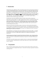
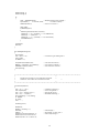
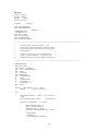
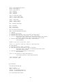
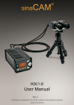
User Display/Control Console
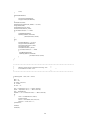
The User Display/Control Console is a handheld ASCII terminal that has two primary functions.
•
•
Allow the operator to start/stop the logging of flight data and optionally mark data records
Display the state of the Data Logger and indicate the progress of the logging operations
7
Figure 2: Handheld Terminal
The unit used in this application is the QTERM-II manufactured by QSI Corporation. The particular
model chosen has a backlighted display, RS-232 9-pin “D” type connector, and the wide-temperature
option. The alphanumeric display is four lines of twenty characters each. The unit has a forty (40) key
tactile keypad; of which, five are user-definable. Five light-emitting-diode (LED) indicators are available
for displaying status information in addition to the alphanumeric display.
The five LED indicators are labeled REC, GPS, DIFF, GYRO, and MARK.
•
•
•
•
•
REC indicates that the Data Logger is recording data.
GPS indicates that the GPS receiver is providing 3-dimensional position data.
DIFF indicates differential corrections are being applied to the GPS data.
GYRO indicates that the vertical gyroscope has erected.
MARK indicates that the data being recorded is being “marked” (to aid later analysis).
Below the five LED indicators are five custom keys labeled START-STOP, EXIT, RESTART, CAL
COMP, and TGGLE. These are the only keys that the operator normally uses during operation of the
system.
•
•
•
•
•
START-STOP allows the operator to start and stop logging data. The GPS and GYRO LED’s
must be lit before logging can be started. Logging can be started and stopped as often as required;
all the recorded data is stored in a single file.
EXIT allows the operator to start the shutdown procedures after the final termination of data
logging. "EXIT"ing copies the present data file to floppy disk (if present) and terminates the Data
Logger functions allowing the power to the system to be safely turned off.
RESTART allows the operator to restart data logging after some abnormal behavior terminated the
previous logging session. If restarting is possible, the operator will be informed by text on the
display.
CAL COMP (calibrate compass) allows the operator to command the system to perform an
autocompensation procedure on the magnetic compass system. This key is inoperative if the Data
Logger is presently logging flight data!
TGGLE (toggle) allows the operator to mark portions of the flight for later analysis. Pressing the
key once starts the marking process; pressing the key again ends marking. The marks are numeric
8
tags, incrementing automatically. The operator is informed of the numeric value of the tag by text
on the display. Marking is only functional while the Data Logger is recording data.
No other inputs or keys are required during normal operations of the Data Logger; however, two more keys
are active to control the display functions. See the Operation section for details.
Some additional functions and displays are provided for maintenance purposes; these are discussed in the
section Maintenance and Troubleshooting.
Power Converter
The complete Data Logger requires approximately 4.0 amps from the aircraft 12-volt power buss. The
aircraft power buss and wiring is protected by a 10-amp circuit breaker in the primary power circuit of the
Data Logger. One switching DC-to-DC converters are required in 12-volt aircraft.
A DC-to-DC converter is employed which converts the aircraft DC power to the voltages required to
operate the single board computer and other components that require compatible regulated voltages (the
Display/Terminal and the Compass System).
The input of the primary converter (for the Beech Sundowner) is 12 volts DC, the outputs are
• +5 volts DC regulated
• -5 volts DC regulated
• +12 volts DC regulated
• -12 volts DC regulated
The DC-to-DC converter used is the Model PD110-40L by International Power Sources, Inc. This unit
requires an input of 10 to 20 volts DC and provides the four regulated output voltages listed above. The
unit is capable of providing + 5 volts DC @ 10 amps, + 12 volts DC @ 9 amps, –12 volts DC and – 5 volts
DC both @ 1 amp (total power output not to exceed 110 watts). The + 5 volt output is over-voltage
protected and all outputs are over-current protected.
3. Software
System Operating Software
The software for the Data Logger was developed using Borland C++ Version 3.1; however, the code is all
standard C with no C++ extensions. An asynchronous communication library, Greenleaf CommLib Level
2, was used to provide a more robust serial communication environment than is natively available in the
Borland product. Software drivers for the analog-to-digital converter system were provided by the
manufacturer, Industrial Computer Source.
The objectives and constrains on the software design are outlined in the following list.
•
•
•
•
Simple and easy to use; placing as little additional workload on the operator as possible.
Self-diagnostics of sub-systems on start-up.
As immune from operator error as practical.
Capable of recovery from in-process errors.
The program requires a file called logger.ini to function. This file contains the system identification (A or
B, as presently only two systems have been constructed), the path or directory into which the logger data
files are to be placed, and calibration data for the analog channels which are hardware dependent (pitch,
roll, ball, and airspeed). This allows re-calibration of the system without the need to re-compile the basic
program.
9
Most of the inputs are channeled through hardware interrupt serviced input/output ports to insure that data
from the external devices is received without loss of information. A system of flags and semaphores are
used to indicate when data is available for each module to process, thus allowing the software to bypass
modules which need not be run at that particular instant.
After the initialization of the sub-systems, the program enters the main program loop; each function within
the loop performs a specific, relatively short task on the data available to be processed and then passes
control the next task. By these means, an operating system, which was never designed to be multitasking,
can be manipulated into a multitasking function. For example, one task reads available characters from the
GPS system and places them in a buffer (temporary storage). This routine places each message in a
separate buffer and sets a flag if a complete message is available. Later, another task interrupts the
buffered message and acts upon the result. In the meantime, other tasks are performed (such as servicing
the analog-to-digital converter system, scanning for and acting upon operator keyboard input, processing
data, storing data, and updating the LED’s and text messages of the terminal). When operating and
collecting data, this loop is executed approximately three hundred times per second.
A data record is taken each second and stored to a temporary buffer. Every ten seconds, this buffer is
written to the fixed disk and the file is closed. This procedure ensures that if software or hardware failure
occurs during a flight logging session, the data recorded (with the possible exception of the last ten
seconds) is saved and recoverable.
The logger data is stored to the fixed disk in binary format that minimizes the time and disk space required
to store each record. A binary record is only 60 bytes long. One hour of flight data occupies only 211
kilobytes of storage and thus a data file representing more than six hours of flight data can easily be stored
on a 3 ½” floppy disk.
When the operator ends a logging session and exits the program, the recorded data file is copied to the
floppy disk automatically. If this operation fails for any reason (no disk present, disk not formatted, or
some other reason), the file is retained and written to the floppy disk on the next opportunity. In any event,
the data files are always retained on the fixed disk and may be retrieved using standard DOS command-line
procedures.
The program consists of multiple modules, the source code for which may be found in Appendix 7.
Post Flight Data Conversion Software
As noted above, the flight data files are stored in binary for reasons of minimizing the file writing time and
to allow them to be easily transported via floppy disks. Although the binary format uses standard IEEE
floating point formats, it was determined that conversion to a standard text (ASCII) format would allow the
maximum flexibility in viewing and analyzing these data.
Programs have been written to read the binary data files and convert the records to text format (ASCII). In
the converted ASCII file, “tab” characters separate the fields of each record and records are separated by a
carriage-return/line feed (newline) character(s).
There are two versions of the conversion program; these differ only in the treatment of the horizontal
position information. The standard horizontal position output of the Global Positioning System Receiver is
latitude and longitude. The first version of the conversion program (convert.exe) directly converts this
data to the ASCII format. The second version (con-utm.exe) converts the horizontal position data to
Universal Transverse Mercator (UTM), in place of latitude and longitude. UTM uses “northing” and
“easting” as the coordinates (in addition to a UTM zone number).
10
The advantage of using UTM coordinates is that UTM is a rectilinear system. This simplifies the process
of plotting the aircraft’s’ course. The “northing” and “easting” coordinates are expressed in meters and are
converted from the latitude/longitude data to a resolution of one meter in this application.
The source code for both conversion programs may be found in Appendix 7.
4. Operation
General Operational Procedures
The initial display on the handheld display/control console is a sign-on message indicating the SystemID
and software version. This is followed by a check for the presence of a floppy disk in drive A and giving
the operator the opportunity to insert one. If a disk is present, an estimate of the flight length (in hours) that
can be stored on this floppy is displayed. If there is no disk in the drive, the program continues after a short
delay.
The system then displays the magnetic heading to allow the operator to judge if the system compass and
aircraft compass agree. Pressing ENTER terminates this display.
As soon as a GPS lock is obtained, the system clock is synchronized to UTC (Zulu) time!
LED’s on the terminal are illuminated to indicate:
•
•
•
GPS position fixes are available [GPS]
Position data are differentially corrected [DIFF]
System vertical gyro has erected [GYRO]
Once these three conditions are true (LED’s lit), the message “READY” will be displayed and pressing the
START/STOP key begins recording data. In the present version, differential corrections are not required to
start logging data. The REC LED will light; indicating recording is in progress. The top line of the display
will indicate the number of records that have been recorded; this number will continue to increment as long
as the unit is recording flight data.
After ten seconds, the automatically generated filename will be displayed. The filename format is
[SystemID] [day] [hours] [minutes]. [year] [month]; e.g. A072115.985 is the filename of the flight data
taken with System “A” beginning at 2115Z on May 7, 1998.
Once recording, the operator may press TGGLE to flag certain critical segments of flight data records. The
MARK LED will light and all subsequent records will be marked until TGGLE is pressed once again. A
mark is an integer recorded in the record, beginning at one (1) and incremented upon each use of the
marking function. The bottom line of the display indicates the present state of the marking function and the
present or last marking number used.
If the GPS signal or differential corrections are lost while recording, the recording will continue with no
position or altitude data in the first case or with loss of precision in the second. The appropriate LED will
blink rapidly to signal the loss of either function.
Pressing START/STOP once again terminates recording of data.
Pressing the EXIT key will attempt to write the recorded data to the floppy disk. Regardless is the success
or failure of this operation, the system will shut down the interfaces to the data systems and inform the
operator when it is permissible to shut off the power to the system.
11
Errors and Recovery
There are many possible fatal (and non-fatal) errors, which will be trapped, and a message displayed on the
handheld terminal! There will be, no doubt, other faults in the hardware and software which may just
STOP the system with NO displayed error message. If an error message is displayed (or if the logging just
stops inexplicably), pressing the “reset” button on the Data Logger or turning the power switch OFF and
then back ON will re-initialize the system.
In any event, if the system was recording, a process is in place that allows the operator to restart recording
data to the original file.
If restart is possible, the sign-on message, check for disk, compass checks, and gyro check will be
bypassed. The message “Restart Possible” will be displayed!
The operator may press RSTRT on the handheld terminal to resume recording (if the GPS LED is lit).
If it desired that subsequent flight data be recorded to a new file, the aircraft must be flown straight and
level until the GYRO LED is lit; then if the GPS LED is also lit, pressing the START/STOP key begins
recording to a new file.
Other Features
Calibrate Compass: When NOT recording data, the operator may press CAL COMP to begin a compass
calibration (autocompensation) procedure. Messages on the handheld terminal will guide the operator
through the series of steps required to do an eight-point ground calibration of the magnetic compass engine.
The operator may abort this procedure at any time. The unit displays information on the accuracy of the
calibration upon completion. Details on this procedure may be found in the Maintenance and
Troubleshooting section.
Display Contrast: By pressing “C” on the keypad, the operator can increase the display contrast on the
terminal. Each press increases the contrast until maximum contrast is reached and then “wraps around” to
minimum contrast.
Display Backlight: By pressing “B” on the keypad, the operator may toggle the backlighting on the LCD
display.
File Recovery: If after a flight the data file is not copied to the floppy disk for any reason, that file is
retained on the hard disk marked as not copied. The next time the system is used, any un-copied data files
previously stored will be copied to the floppy disk in addition to the data file just recorded. One floppy
disk can contain approximately 6.75 hours of flight data.
By starting the Data Logger and NOT pressing START but pressing EXIT, an operator may copy any
previously un-copied data files from the system’s fixed disk on a floppy.
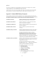
Operational Error Codes
The following table contains the Error Codes displayed on the handheld terminal when an unrecoverable
(fatal) error occurs during a data logging session. In the event that a fatal error is encountered, the operator
should make note of the displayed Error Code to facilitate the remediation of the problem.
12
If an Error Code is displayed in the course of a recording session, it is recommended that a “reset” followed
by a “restart” (as mentioned in the previous section) be attempted. Note that in any event, pressing the
“reset” button on the Data Logger will require a minute or so before the system appears to respond! This
delay is caused by the necessity of re-loading the operating system followed by the actual program.
If this fails to resolve the problem, the Data Logger should be powered down and the logging session
cancelled until the required maintenance can be performed.
Table 1 Data Logger Error Codes
Error Code
A001
A002
A003
A004
C001
C002
G001
G002
G003
G004
G005
G006
G007
G007a
G008
G009
G010
G011
G103
I001
I002
I003
I004
S001
S002
W001
W002
W003
Description
Error initializing the analog-to-digital converter!
Error initializing an A/D conversion cycle!
Error starting an A/D conversion cycle!
Error reading data from an A/D conversion!
Magnetic Compass fails to respond to commands!
Failed to obtain magnetic heading!
Could not send command to GPS receiver!
Could not reset the GPS receiver!
Could not set initiate low dynamics in GPS receiver!
Could not set navigation mode in GPS receiver!
Could not start WAAS mode of the GPS receiver!
Could not set ION mode of the GPS receiver!
Could not set WAAS POS mode of the GPS receiver!
Could not set WAAS precision mode of the GPS receiver!
Could not request WAAS INF message from the GPS receiver!
Could not request NMEA GGA message from the GPS receiver!
Could not request NMEA POS message from the GPS receiver!
Could not request WAAS WCA message from the GPS receiver!
Could not change baud rate of the GPS receiver!
Error initializing 16550 serial UARTs.
Error initialing COM3 serial port (compass).
Error initialing COM1 serial port (GPS receiver).
Error initialing COM2 serial port (terminal).
Failed to find file logger.ini! This file must be present for the system to start!
Data in file logger.ini is incomplete or corrupt!
Error opening data file!
Error writing to the data file!
Error closing the data file!
Structure and Content of Data Files
Each data file is automatically assigned a unique name when a logging session is started. This is done to
minimize the number of steps the operator must do to record a session. The file is named using a
combination of the System identifier, the date, and the time (Zulu or Universal Coordinated Time) which
the particular logging session was started.
13
The format is {SystemID}DDHHMM.YYM where
•
•
•
•
•
•
{SystemID} is the character ‘A’ or ‘B’
DD is the two digit day of the month
HH is the two digit hour of the day in 24-hour format
MM is the two digit minute of the hour
YY is the last two digits of the year
M is a character representing the month (1-9, A=Oct., B=Nov., and C=Dec.)
As noted previously, the Data Logger files are stored in binary format. The details of the binary storage
format is defined by the C ‘structure’ record which may be found in any of the program listings in
Appendix 7. Note that an ‘int’ is a 16-bit and a ‘long (int)’ is a 32-bit integer. A ‘float’ is equivalent to the
32-bit floating point and a ‘double’ is equivalent to the 64-bit floating point representation defined by
ANSI/IEEE 754-1985: IEEE Standard for Binary Floating-Point Arithmetic.
Since it was never intended that the data files be read directly in binary format, the above is more for
informational than practical purposes. The following tables indicate the variables stored in the files. The
first is exactly the same variables and in the same order as the raw binary data files described above.
Table 2 Legend for Latitude/Longitude ASCII Conversion
Column Heading
Description
Time
Universal Coordinated Time
Mark
Observer Data Mark
Mode
GPS Operational Mode1
Lat
Latitude in WGS-84 Datum
Long
Longitude in WGS-84 Datum
Alt
Rate_of_Climb
Airspeed
MagHeading
Pitch
Roll
Ball
CDI_1
Altitude Above MSL
Vertical Speed
Indicated Airspeed
Magnetic Heading
Pitch Attitude
Roll Attitude
Coordination (Yaw)
VOR/LOC # 1 Course Deviation
T_F1
Flag1
CDI_2
T_F2
Flag2
GSCDI
#1 To-From Indicator
VOR/LOC # 1 Flag
VOR/LOC # 2 – Same as Above
GS Flag
COS
SOG
Glideslope Flag
Course Over Ground
Speed Over Ground
Glideslope Course Deviation
1
Format and Limits
HHMMSS
Auto incrementing integers
0 = none, 2 = non-diff, 3 = diff
(+ or −) ddmm.mmmmm
+ indicates North Latitude
(+ or −) dddmm.mmmmm
+ indicates East Longitude
Units of feet
Units of feet/minute
Units of Knots
Degrees
Degrees (+ nose up)
Degrees (+ right)
Units of “Ball Width”
Percent Full Scale (limit at 120)
+ right
1 = TO, -1 = FROM, 0 = none
1 = GOOD, 0 = FLAGGED
Same as VOR/LOC CDI’s
+ up
Same as VOR/LOC Flags
Degrees – Derived by GPS
Knots - Derived by GPS
The Mode of the Data Logger, which employs WAAS correction, has the decimal number 200 added to
the mode value to differentiate the data from the original, which used DCI RTCM corrections.
14
Table 3 Legend for UTM ASCII Converted Files
Column Heading
Time
Mark
Mode
Zone
Northing
Easting
Description
Universal Coordinated Time
Observer Data Mark
GPS Operational Mode2
UTM Zone
UTM Northing Coordinate
UTM Easting Coordinate
Alt
Rate_of_Climb
Airspeed
MagHeading
Pitch
Roll
Ball
CDI_1
Altitude Above MSL
Vertical Speed
Indicated Airspeed
Magnetic Heading
Pitch Attitude
Roll Attitude
Coordination (Yaw)
VOR/LOC # 1 Course Deviation
T_F1
Flag1
CDI_2
T_F2
Flag2
GSCDI
#1 To-From Indicator
VOR/LOC # 1 Flag
VOR/LOC # 2 – Same as Above
GS Flag
COS
SOG
Glideslope Flag
Course Over Ground
Speed Over Ground
Glideslope Course Deviation
Format and Limits
HHMMSS
Auto incrementing integers
0 = none, 2 = non-diff, 3 = diff
Integers between 1 and 60
Meters north of the Equator
Meters East of Central Meridian
For this Zone + 500,000
Units of feet
Units of feet/minute
Units of Knots
Degrees
Degrees (+ nose up)
Degrees (+ right)
Units of “Ball Width”
Percent Full Scale (limit at 120)
+ right
1 = TO, -1 = FROM, 0 = none
1 = GOOD, 0 = FLAGGED
Same as VOR/LOC CDI’s
+ up
Same as VOR/LOC Flags
Degrees - Derived by GPS
Knots - Derived by GPS
Post Processing Procedures
A mentioned above, the Data Logger produces a copy of the data file on a 3½” floppy disk at the end of
each logging session. This file is in the binary data format. The Post Flight Data Conversion Software is
used to convert these files to ASCII (text) format. The program is used depends on if the horizontal position
data is desired in latitude/longitude (convert.exe) or in Universal Transverse Mercator (utm_con.exe)
format.
The data file is copied to the directory of the computer that contains the conversion program executable
file. The program (either convert.exe or con-utm.exe) is run and the user must enter the name of the data
file to be converted. Each program allows the user to select subsets of the records to be converted. The
user may 1) convert all records, 2) convert only “marked” records, or 3) convert only a decimated number
of records (with the choice of the decimation factor). Once this selection is made, the program writes the
converted file in the same directory with only the “extension” of the file name changed. For example, if the
file name to be converted was A111407.98B, the resulting ASCII file will have the name A111407.txt. As
a practical matter, if the conversion is being run on a Windows 9x or NT computer, the file is manually
renamed including the original extension plus the “txt” extension (A111407.98B.txt). This is a legal file
name construct in these operating systems.
2
The Mode of the Data Logger, which employs WAAS correction, has the decimal number 200 added to
the mode value to differentiate the data from the original, which used DCI RTCM corrections.
15
These converted data files can then be processed by any of a number of software packages depending on
the desired analysis to be performed. In the particular experiment for which the Data Logger was
developed, this program is a highly modified Microsoft Excel based application.
5. Maintenance and Troubleshooting
General System Software Configuration
System Start Up
The autoexec.bat file found in the root directory of the fixed disk is configured to change the default
directory to that in which the Data Logger software resides and to execute the Data Logger software:
gpstest.exe.
In the event that the Data Logger system requires maintenance, these lines of the autoexec.bat file may be
“commented out” so that the system comes up in the standard MSDOS command-line mode. See the
section on General Computer Problems for a procedure that may be used.
The boot sequence, which is configured from the CMOS setup of the single board computer, is also
modified to facilitate the operation of the system as a Data Logger. To boot from a floppy disk, the CMOS
setup must be changed. See the section on General Computer Problems for details.
Logger Parameter File
A file named logger.ini is used to define the identification of the system, certain analog calibration
parameters, and the directory to which the generated data files will be stored on the fixed disk. This file
must be present in the same directory as the main Data Logger executable file: gpstest.exe.
Each line begins with the name of parameter defined by that line and must be exactly as appears in the
example below. All ten parameters must appear in the file but may be in any order. Any spaces before and
after the “=” sign are ignored.
“SystemID” shall be a single character. “DataDirPath” shall be an ASCII string containing no spaces and
having the “back-slash” replaced by a “forward-slash” (contrary to normal MSDOS usage for path
specifiers). The last “forward-slash” must be present! “DataDirPath” should never be empty nor should it
reference the root directory of a disk drive! The remaining values may be specified in signed integer
format or signed floating format (with a decimal point). These parameter (those assigned numerical values)
are used to adjust the translation of the outputs of the gyroscope, pendulum, and altitude pressure sensor for
minor variations of the transducers.
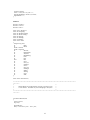
Typical logger.ini file
SystemID = A
PitchOffset = 0.0
PitchGain = 44.3
RollOffset = 0.0
RollGain= 22.1
AltOffset = -1.3
AltGain= 0.32175
BallOffset = 0
BallGain = 1.783
DataDirPath = c:/gpstest/data/
16
General Maintenance and Calibration
Periodic Maintenance
Generally, the Data Logger systems require little maintenance on a regularly scheduled basis. The only
item would be the air filter, which should be checked and cleaned as required every six months.
The only limited life components are the backup batteries (for the CMOS memory and real time clock of
the single board computer, and for the GPS receiver). The batteries should last approximately five years
before requiring replacement
Calibration
The only components that may require calibration (with the exception of the compass engine, the
calibration of which is addressed later in this section) are those associated with the analog systems.
The calibration of the analog-to-digital converter system itself is addressed later in this section and is a
rather lengthy procedure, which is described in the respective manuals of the two components (AD12-8 and
AT16-P). It should be noted that calibration of these components is the only form of adjustment for
correcting errors in the low-level A/D channels (see “Errors in Low Level Channels” later in this section).
The remaining variables (pitch, roll, ball (yaw), and airspeed) may be calibrated by changing the respective
gain and offset parameters in the logger.ini file previously mentioned. Each Data Logger has a program
(adtest.exe) which may be useful in the adjustment of the gain and offset numbers. This file is located in
the same directory as the main Data Logger file (gpstest.exe) and uses the same logger.ini data as the main
Data Logger program. “adtest.exe displays on the VGA display all of the above mentioned variables. It
does not require the compass engine or the handheld terminal to be attached or functional. “adtest.exe”
only requires that the A/D system is operational; i. e. communicating with the single board computer.
Troubleshooting
General Computer Problems
To operate the Data Logger system as a MSDOS computer, a standard PC keyboard and a VGA capable
display must be connected. The keyboard connector is located on the side of the card-cage; the 15-pin
VGA display connector is located on the connector panel of the Single Board Computer (the only fulllength card in the card-cage).
Power the Data Logger system and allow it to start normally. If there were no fatal errors during start-up,
the “enter” key on the handheld terminal will have to be pressed to acknowledge the compass heading
check; then the “EXIT” key should be pressed. The standard shutdown message should appear on the
handheld terminal and the VGA display should provide a standard MSDOS command-line prompt.
In the event that the Data Logger system fails to even boot the MSDOS operating system, a keyboard and
display must be attached and a bootable 3 ½” floppy disk must be available and inserted in the drive.
When the system is powered, press the Del key on the keyboard when prompted to enter the CMOS setup
screens. Once in setup, configure the boot options to allow booting from the floppy disk first, then the
fixed disk. Save the CMOS setting and allow the system to re-boot. The single board computer should
boot the MSDOS operating system from the floppy disk and allow testing to be performed. Diagnostics
should then be performed to determine the cause of the failure to boot from the fixed disk and this
condition remedied.
17
Before returning the system to service as a Data Logger, restore the boot options back to the original
configuration; i.e. boot from the fixed disk only. This setting is chosen so that a user can insert a floppy
disk (used to provide a copy of the Logger data file) at any time without having the system attempt to boot
from the floppy.
At this point, the autoexec.bat file can be edited to comment out the lines that automatically start the Data
Logger software (gpstest.exe). These should be removed before the system id returned to service.
Once the computer is booted and operating in MSDOS, all normal MSDOS functions should be available
and the unit should behave as a standard computer using command at the standard DOS prompt. The
floppy drive (A) and fixed disk (C) should be accessible for both read and write; serial ports COM1 and
COM2 should be available. Note that “COM3” is non-standard and will not be recognized by DOS. Also
there are no active parallel ports in the system!
Executing the file gpstest.exe from its home directory will run the actual logger software. The external
compass system and the handheld display terminal must be connected for the system to start. Furthermore,
if the GPS antenna is not connected and receiving a signal, the Data Logger will not be allowed to enter the
logging mode.
Compass System Problems
Accuracy
If the Data Logger does not provide an error message related to the compass system (type C) but the data
provided by the system appears to be erroneous; the first step would be to perform a new calibration
(autocompensation) procedure.
This is accomplished by powering the Data Logger and moving the aircraft to an area free from metal
structures and underground electrical power cables. This procedure is most easily accomplished with two
operators: one to maneuver the aircraft and one to operate the handheld terminal. The aircraft must be
maneuvered to eight (8) distinct headings during this process. The operators will be guided through the
procedure by a sequence of messages on the Console. At the end of a successful calibration procedure, two
single digit numbers are displayed (0-9): the higher the numbers, the better! The first digit represents the
quality of the compensation (a score of “7” or above indicates an accuracy of 2 degrees or better). The
second digit represents the quality of the magnetic environment (a score of “5” or better is acceptable). If
acceptable scores are not achieved, the procedure should be repeated after moving the aircraft to a different
physical location.
If calibration does not correct the problem, the optimum diagnostic procedure would be to substitute a
KVH C100 compass from another Data Logger system to verify the problem is the compass engine. If the
replacement unit solves the problem, the defective unit should be returned to the manufacturer for repair or
replacement3.
If the substitution of the compass engine does not solve the problem, the difficulty may be associated with
the aircraft. Changes in the location of the compass system or additional pieces of equipment recently
installed near the compass engine location may effect accuracy. Changes in the aircraft wiring in the area
of the compass may also have the same effect. It is also possible that the aircraft’s engine or generating
system may be producing electrical noise that may interfere with proper operation of this electronic
compass engine.
3
If a new C-100 Compass System is acquired, it must be configured using the software provided by the
manufacturer. See Appendix 3 for details.
18
Communications
If the Data Logger does display an error message (a C001 or C002 fatal error), first check the cable
between the Data Logger and the compass system. If the cable was securely connected, disconnect the
cable from the compass system end and measure the voltage between pins 5 and 8 of the 9-pin connector.
With the Data Logger turned on, there should be 12 volts DC present; pin 8 being positive.
There are only two items (besides the cable and the lack of DC power) which can cause a communication
failure. One is the compass system itself and the other is the SIIG input/output board. Replace these items
(with units from another Data Logger) one at a time to isolate the problem4.
GPS System Problems
The Global Position System receiver (Ashtech G12) provides the total positioning information for the Data
Logger. The Ashtech G12 receives both the standard GPS satellites and differential corrections from the
WAAS satellites.
GPS Receiver System
If the GPS receiver has a problem, the operator will observe one of the following symptoms,
•
•
•
A Fatal Error of Type G will be displayed on the console.
The GPS LED on the console will fail to light.
Excessive time is required for the GPS LED to light (in excess of two minutes).
The Ashtech G12 GPS receiver has an indicator mounted on the circuit board that contains both red and
green LED’s. Flashing red indication means the receiver has power (+5 volt DC). The green LED flashes
between the red flashes. Each green flash indicates one satellite locked (being received and processed), e.g.
four (4) green flashes indicates four satellites locked. The unit must be locked on to a minimum of five
satellites (four GPS and WAAS) for the Data Logger to operate.
If a fatal error of type G was displayed, check the power to the Ashtech G12 receiver. Verify that the 9-pin
connector labeled Port A is firmly connected to the COM1 serial port of the single board computer. If
neither of the above is the cause of the problem, the COM1 serial port should be checked and/or the
Ashtech G12 should be checked for proper operation independent of one another.
One method is to use a program supplied by Ashtech called Evaluate. This program can be run on a
Windows computer using a serial extension cable to connect the computer serial port to the connector
labeled Port A. This program will communicate with and test any number of Ashtech GPS receiver
systems. A users guide is available for Evaluate 4.0 or above.
If no fatal errors are displayed but the GPS Led never lights to indicate GPS data is available, then the
problem is either in the G12 receiver itself or the GPS antenna system. The LED on the receiver itself can
be helpful in this case. If green flashes are never observed, the most likely cause is either the antenna or the
antenna cabling. The most straightforward method of determining the component(s) at fault is to
interchange to Ashtech G12 receiver with the receiver in another Data Logger (much easier than
interchanging antenna systems).
If excessive time appears to be required for the GPS system to lock onto the required number of satellites,
the problem may be that the “keep-alive battery” that retains receiver data may be exhausted. This battery
4
If the C-100 Compass System is replaced, see Appendix 3 for information on software configuration. If
the SIIG input/output board is replaced, see Appendix 2 for information on the hardware configuration.
19
allows the system to retain it’s last position, the satellite almanac, and satellite ephemeris data. The battery
is located within the silver colored connector near the GPS receiver mounting position. If the battery is
functional, the GPS LED on the handheld display should illuminate within one minute after the
“STARTING” message is displayed.
Wide Area Augmentation System
A problem with the differential correction system will only be evident by the Data Logger never coming
out of “STANDBY” and the DIFF LED never being lit.
All of the processing of the WAAS signal is done within the Ashtech G12 receiver and the only method
one has to determine these internal conditions is to communicate directly with the G12 receiver. A second
serial port is available to which may be connected to a second computer running a terminal emulator
program or the Ashtech Evaluate program. This port always operates are 9600 baud, no parity, and one (1)
stop bit.
Commands may be input using the second computer to determine the internal state of the G12 receiver
including the WAAS setting and data.
The first to be used is “$PASHQ,PAR” which displays the parameters presently in use by the receiver.
The output of this command is shown on page 77 of G12 GPS Board and Sensor Manual. However, an
additional line appears which is not shown which is descriptive of the state of the WAAS process. This
line begins “WAS: 122”. The remainder of this line should contain (in any order) the following: ‘POS:
ON’, ‘COR: ON’, ‘PAR: OFF’, ‘FLT: ON’, ‘ION: ON’, ‘VIT: SFT’, and ‘PRC: ON’. If these are present,
the system is assumed to be operating in differential mode; however, if sufficient WAAS corrections have
not been received and decoded, the DIFF LED may not be lit.
If ‘COR: OFF’ is observed, the receiver may not be receiving the WAAS satellite. This can be verified by
the command “$PASHS,WAS,INF,B,ON”. See Appendix 5 for an explanation of the output generated by
this command. The INF message will be output once per second. If the characters just before the asterisk
are NOT “3F”, the WAAS corrections are NOT being received. Use the command
“$PASHS,WAS,INF,B,OFF” stop this message.
If the INF message indicates proper reception of the WAAS signal, use the command
“$PASHS,WAS,WCA,B,ON” to view the actual WAAS data being applied to the positional solution. See
Appendix 5 for an explanation of the output generated by this command. This message must contain five
or more satellites for which the flag if either ‘G’, ‘H’, or ‘U’ before the position is marked as differentially
corrected.
A/D Problems
Analog-to digital converter problems may be of several levels of severity. Each of these will require a
somewhat different approach in troubleshooting. The A/D system itself consists of two discrete circuit
boards: the main A/D converter (AD12-8) which is located in the computer card-cage, and the multiplexer
board (AT16-P) mounted on the side of the Data Logger enclosure. Each of the multiplexer channels used
is wired to one of the internal sensors or to the external radio-navigation outputs of the aircraft. The radionavigation signals pass through a set of relays used for emergency isolation of the Data Logger and
essential navigation displays.
Each of the following paragraphs describes a particular class of A/D problem.
20
Error Codes Displayed
If an A/D error code is displayed on the handheld terminal (type A), the problem is localized to the two
circuit boards mentioned above or the cable, which connects the two boards. Verify that the AD12-8 is
properly seated in the card-cage and that the cable is firmly seated to each mating connector. If the
problem persists, replace the AD12-8 and AT16-P one at a time to determine which has failed. The AT16P can be substituted by merely unplugging the cable from the installed unit and plugging it into the spare;
there is no need to remove the original unit nor to connect the inputs to the spare AT16-P used for testing
purposes. If this procedure is used, be certain that the replacement AT16-P is placed on an insulating
surface before applying power.
Spare AD12-8 and AT16-P are available (already properly configured) in addition to a spare cable used to
connect these units.
Operational Checks Using the Terminal
If no errors are flagged but it is suspected that there is a problem with one or more of the analog-to-digital
channels, the actual converted data from these channels can be displayed on the handheld terminal to aid in
maintenance and troubleshooting.
When the Data Logger is in the recording mode, the actual values being stored in the flight data records for
pitch, roll, airspeed, ball (yaw), and radio-navigation course-deviation-indicators (CDI’s), and associated
flags can be displayed on the third line of the alphanumeric display.
•
•
•
•
•
•
Pressing “1” displays the pitch and roll in degrees (positive is right or up)
Pressing “2” displays the airspeed in knots and the ball position in unit of “ball width”
Pressing “3” displays the VOR/LOC #1 course deviation in percent and the TO-FROM status
Pressing “4” displays the VOR/LOC #2 course deviation in percent and the TO-FROM status
Pressing “5” displays the Glideslope course deviation in percent and the flag status
Pressing “0” clears the display
Errors in High Level Channels
The high level channels are defined as those for which the gain of the A/D system is less than five. These
include:
• pitch data
• roll data
• yaw or ball data
• airspeed data
If yaw and airspeed high level inputs are both exhibiting errors, the common source may be the +10 volt
precision reference voltage that is used to excite these sensors. This reference voltage is generated on the
AD12-8 board, routed to the AT16-P via the interconnecting cable, and is distributed to the sensors via a
terminal strip located near the AT16-P board.
If the error is limited to a single high level channel, examine the wiring to between that sensor and the
AT16-P. If both the pitch and roll channels are exhibiting errors, the vertical gyroscope may be at fault.
The detection of the fault is most easily accomplished by substitution of components (the vertical
gyroscope/pendulum assembly or the differential pressure assembly (in event of an airspeed problem).
21
Errors in Low Level Channels
The low-level channels are those associated with the radio-navigation instruments. These signals are not
“low level” in the strictest sense of the term but these channels are measuring differential voltage inputs in
the millivolt range (±200 mv range).
If all of these channels are not responding correctly, examine the external connector between the Data
Logger and the aircraft (the larger of the two circular connectors). Secondly, verify that the isolation relays
are operating (these relays should be activated when power is applied to the Data Logger system. Another
possibility is that the zeroing of the multiplexer and/or analog converter may have drifted to an extent
which effects these millivolt range measurements without effecting the apparent accuracy of the high level
channels. This occurrence would be rare, but if suspected, the procedure for calibration and zeroing of
these components is described in the respective product manuals but is too involved to be included here.
If the errors are restricted to a subset of the level-level inputs or to only those from a particular instrument
(VOR#1, VOR#2, or GS), the most likely cause is a wiring fault.
Use in 24-Volt Aircraft
The Data Logger was originally constructed for use in an aircraft with a 12-volt DC power buss. In order
to convert the unit to operate in a 24-volt aircraft, a number of component and wiring changes are required.
The time required to convert one Data Logger from 12-volt to 24-volt operation is estimated to be less than
two hours.
Components Required (for each Data Logger)
•
•
•
Power Converter - International Power Sources, Inc – Model PD110-40M
Relays - Potter & Brumfield – Model KHAU17D13 5 (3 pieces)
Fan – Papst – Model 4314 or equivalent (24 VDC Brushless, 4.7 inch square mount)
Procedure
1.
2.
3.
Remove the International Power Sources PD110-40L Power Converter and install the model PD11040M in its place. It is the same physical size and is a pin-for-pin replacement (no modifications need
be made to the cabling).
Remove the three or four P&B relays and replace with the 24 VDC units.
Remove the 12 VDC fan assembly and replace with the 24 VDC unit.
Optionally, the Data Logger power switch/circuit breaker may be replaced with a unit rated a 5 amperes.
Acknowledgments and Disclaimer
The work supporting this Technical Report was supported under Federal Aviation Administration (FAA)
Cooperative Agreement Award Number 2001-G-037 with the Institute of Aviation, University of Illinois at
Urbana-Champaign. The FAA technical monitor for this research grant is Dr. Dennis B. Beringer, AAM510; the FAA Grants Analyst administering this grant is Mrs. Colleen Peranteau, ACT-50. This report is in
the process of review and approval and is not at present an official FAA document. Consequently, the
views expressed herein do not necessarily represent official FAA positions.
5
The contacts of the selected relay should be a minimum of gold flashed since the signals passing through
are small and any excess contract resistance may effect the accuracy of the radio-navigation data.
22
References
Benton, C.J., Corriveau, P., & Koonce, J.M. (1993). Concept Development and Design of a SemiAutomated Flight Evaluation System (SAFES), AL/HR-TR-1193-0134
DOD (1992). Mapping Datum Transformation Software. NTIS PB93-500296
Taylor, H.L., Bradshaw, G.L., Talleur, D.A., Emanuel, T.W., Hulin, C.L., Lendrum, L., & Vaughn, J.A.
(1999) Effectiveness of Personal Computers to Meet Recency of Experience Requirements, Proceedings of
the Tenth International Symposium of Aviation Psychology, Columbus, OH: The Ohio State University.
Lendrum, L., Taylor, H.L., Talleur, D.A., Hulin, C.L., Bradshaw, G.L., & Emanuel, T.W. (1999) Airborne
Flight Data Recorder, Proceedings of the Tenth International Symposium of Aviation Psychology.
Columbus, OH: The Ohio State University.
Hardware and Software Reference Manuals
Evaluate 4.0 – Users Guide (1997), Sunnyvale, CA: Ashtech
G12 GPS Board and Sensor Reference Manual (2000), Santa Clara, CA: Magellan Corporation
Greenleaf CommLib - Reference Manual (1997), Dallas,TX: Greenleaf Software, Inc.
I/O Professional User’s Manual (1997), Fremont, CA: SIIG, Inc.
KVH C100 Compass Engine – Technical Manual (Rev. G1), Middletown, RI: KVH Industries, Inc.
Minimum Operational Performance Standards for Global Positioning System/Wide Area Augmentation
System Airborne Equipment (1999), RTCA/DO-229B
Model SB486PV Product Manual (1995), San Diego: Industrial Computer Source
Model AD12-8 Product Manual (1996), San Diego: Industrial Computer Source
Model AT-16P Product Manual (1997), San Diego: Industrial Computer Source
QTERM-II User’s Manual, Revision 10 (1997), Salt Lake City: QSI Corporation
VG400 Series User’s Manual, Revision A (2002), San Jose, CA: Crossbow Technology, Inc.
23
Appendices
Appendix 1 – BIOS Settings for Single Board Computer
In general, most of the settings within the BIOS (CMOS setup) of the SB486PV single board computer
remain as configured in the standard factory defaults. In addition to the microprocessor and ISA buss
controller, only the hard disk controller, the floppy disk controller, and the serial ports are essential for Data
Logger operation.
It should be verified that the two on-board serial ports are configured in the standard manner; i. e. COM1 at
port 3f8 hexadecimal and IRQ 4; COM2 at port 2f8 hexadecimal and IRQ 3.
Because both IRQ 5 and IRQ 7 are required for other devices by the Data Logger hardware, the on-board
parallel port on the SB486PV must be disabled.
Since it is the normal operating procedure to insert a floppy disk in the Data Logger before applying power,
the boot sequence of the SB486PV must be modified. The BIOS must be configured to attempt to boot
from only the fixed disk, never the floppy.
Appendix 2 – Configuration of Third Serial Data Port
The SIIG I/O Professional multifunction input/output board, Model IO1809, used in this application
requires that only one serial port be active and that the other serial port and the parallel port be disabled.
The board is configured by means of jumpers. There are fifteen sets of three pins each; the sets are labeled
JP1 through JP15. Each set may be jumped in three ways,
•
•
•
H; the center and upper pins jumpered
L; the center and lower pins jumpered
Open; no jumper installed
The following table documents the jumper configuration used in the Data Logger.
Table 4 SIIG I/O Board Configuration
Position
JP1
JP2
JP3
JP4
JP5
JP6
JP7
JP8
Jumper
H
L
L
L
L
H
L
L
Position
JP9
JP10
JP11
JP12
JP13
JP14
JP15
Jumper
OPEN
OPEN
OPEN
H
OPEN
OPEN
OPEN
24
Appendix 3 – Configuration of the KVH Compass System
The KVH C100 compass system is configured by software supplied by the manufacturer. This is MSDOS
program but can be run within the Windows environment. The files C100USR.EXE and CLIST.TXT
must be copied to a directory and the executable run from that directory.
Since the C100 compass system is mounted in separate enclosure and both the RS-232 serial
communications and the DC power are routed through the single interconnection cable, the following
procedure should be used to run the setup program. Use a serial extension cable to connect the computer
running the C100USR program to the cable in the Data Logger which is normally connected to COM3 (the
serial port which is associated with the SIIG I/O Professional multifunction input/output board). This
allows the Data Logger to supply the 12 VDC to power the compass engine.
The compass engines used in the Data Logger are set to communicate at 9600 baud; however, the default
baud rate of a new unit is 4800 baud. The parameters should be set as follows:
•
•
•
•
•
•
•
•
Heading Type: magnetic
PowerUp Mode: Not Sending
Baud Rate: 9600
Message Units: d (degrees)
Output Type: 0
Output Format: 0
Damping Type: 3
Damping Rate: 0
The Data Logger sends a type “d1” command to the compass engine to read the present heading in degrees
and does not expect to see any output from the compass engine except responses from such commands. If
the PowerUp Mode is inadvertently set to sending, the Data Logger will flag an error immediately.
Calibration should always be performed using the Data Logger built-in feature with the entire system
mounted and configured in the airframe in which the system will operate.
Appendix 4 – Configuration of the A/D System
AD12-8
The AD12-8 is configured for ±5 volt input (bipolar). Analog-to digital conversions are started using the
on-board counter/timer. The unit is configured to interrupt the main processor on end-of-conversion
(EOC). The base I/O address is 310 hexadecimal and the interrupt output is selected as IRQ 7 (IRQ3-5 are
used by the serial ports).
A DIP switch S1 configures the base address; the individual switches are labeled A3 through A9. Switches
A3, A4, and A6 are ON and the remainder are OFF to configure the address of 310 hexadecimal.
Jumpers accomplish the remainder of the configuration and these are set as listed below.
• BIP/UNIP jumper set to BIP
• 10V/5V jumper set to 5V
• CLK0 jumper present
• TMR/EXT jumper set to TMR
• EXT/EOC jumper set to EOC
• IRQ jumper set to IRQ7
25
AT16-P
The AT16-P is configured to use programmable gain settings and is set to output ±5 volts. All other
settings and jumpers are on the standard default settings (if present).
A DIP switch S1 on the AT16-P board configures these setting. The individual switches labeled GM0,
GM1, and GM2 are set OFF; the remainder (labeled G/2, SHO, GP0, GP1, and GP2) are set ON.
Appendix 5 – Ashtech WAAS Software Commands
The G12 software (Version Gt35) has been modified to receive and apply the WAAS corrections to the
positional data output of the receiver. The following are some of the commands added and do not appear in
the Ashtech G-12 Reference Manual; only those actually used in this application are described.
$PASHS,WAS,OFF/prn:
Disables or enables the receiver to search for the WAAS
satellite (prn is the satellite number, 122 in this case).
$PASHS,WAS,POS,OFF/ON
Disables or enables the use of the position of the WAAS
satellite in the positional computation.
$PASHS,WAS,COR,OFF/ON
Disables or enables the application of the WAAS data to the
positional computation.
$PASHS,WAS,PRC, OFF/ON
Disable or enables the “precision” mode of WAAS
corrections.
$PASHS,WAS,INF,port,OFF/ON
Disables or enables information to be sent to “port” (either A
or B) describing the reception status of the WAAS signal.
The format of the information message is as follows:
$PASHR,WAS,INFsat,sig,lock where sat is the WAAS
satellite number, sig is the signal strength, and lock is a bitmapped field indicating the state of the various decoding
processes (a lock value of "3F” is fully locked). This message
is output once per second until turned off by command.
$PASHS,WAS,WCA,port,OFF,ON
Disables or enable information to be sent to “port”(either A or
B) describing the corrections being applied to the positional
computation by WAAS data.
The format of the information message is as follows:
$PASHR,WAS,WCA,num,…. Where num is the number of
satellite records in the remainder of the message.
Each satellite record consists of seven (7) fields
1. Satellite PRN number
2. Fast correction (WAAS)
3. Long term correction (WAAS)
4. Ionospheric correction (WAAS)
5. Tropospheric corrections
6. Sum of all used correction
7. Flag of used WAAS corrections where flag is
• “-“ - no corrections
• “F” - only fast
26
• “L” – only long term
• “S” – fast and long term
• “I” – only ionospheric
• “G” – fast and ion
• “H” – long term and ion
• “U” – all corrections
This message is output once per second until turned off by
command.
Appendix 6 – Initial Settings for Display/Control Console
The QTERM-II is configured via software provided by the manufacturer. The program QSETUP.EXE is
used to program the terminal using a “QDATA File.” The QDATA File is an ASCII file provided by the
manufacturer in several versions for the various models of the QTERM-II terminal. The particular file
appropriate to this unit is QDATA40W.V30.
Several changes were made to this default file in order to utilize the display more conveniently and to
simplify the task of communicating with the terminal. Specifically the lines identified below were
modified.
•
•
•
•
•
•
•
•
[auto wrap mode]
off
[auto scroll mode]
off
[auto line feed mode]
off
[key repeat mode]
off
<k00>’~5’
<k01>’~4’
<k03>’~2’
<k04>’~1’
<sk00>’~5’
<sk01>’~4’
<sk03>’~2’
<sk04>’~1’
<k02>’~3’
<k05>
<sk02>’~3’
<sk05>
The result of loading this modified configuration is twofold.
1.
2.
All twenty character positions on each of the four lines of the display can be written to without
changing the display on any other line in the process, and
The data sent when a function key is pressed (START/STOP, EXIT, etc.) starts with the tilde (~)
character which is not sent by any other key on the keypad.
Detailed instructions on the use of QSETUP and “QDATA Files” are in Chapter 3 of the QTERM-II User’s
Manual.
The QTERM-II sends and receives data and is supplied +5 VDC power through the single serial cable
connected between the Data Logger enclosure and the unit. Pin 5 is the standard ground pin for 9-pin serial
connectors but pin 9 is used as the +5 VDC input for the QTERM-II. . Use a serial extension cable to
connect the computer running the QSETUP program to the cable in the Data Logger, which is normally
connected to COM2 (the lower serial port on the single board computer card). This allows the Data Logger
to supply the 5 VDC to power the QTERM-II handheld terminal.
27
Appendix 7 – Source Code
System Operation Software
The following modules are compiled together and linked with the a12drvc.obj file provided by Industrial
Computer Source (ICS) and GCLL.LIB provided by Greenleaf Software. Header files are also provided:
a12drvc.h from ICS; ibmkeys.h, asciidef.h, and gsci.h from Greenleaf Software. The memory model
required by the ICS module is the “large” and therefore that model has been used the compilation. The
entry point of the program (main) is to be found in the file gpstest.c.
ADFUNCT.C
#include
#include
#include
#include
#include
#include
#include
#include
#include
<stdio.h>
<dos.h>
<math.h>
<ctype.h>
<bios.h>
<alloc.h>
<stdlib.h>
<conio.h>
"a12drvc.h"
extern float
PitchOffset,
PitchGain,
RollOffset,
RollGain,
AltOffset,
AltGain,
BallOffset,
BallGain;
extern int GyroFlag;
extern struct record
{
unsigned long Time;
int
Mark;
int
Mode;
double Latitude;
double Longitude;
int
Altitude;
int
RateOfClimb;
int
Airspeed;
int
MagHeading;
int
Pitch;
int
Roll;
float
Ball;
int
CDI1;
int
CDIT_F1;
int
CDIFlag1;
int
CDI2;
int
CDIT_F2;
int
CDIFlag2;
int
GSDev;
int
GSFlag;
int
COG;
int
SOG;
};
extern struct record Record;
28
extern
extern
extern
extern
int ADCount;
unsigned LoopCounter;
int ADInProgressFlag;
int ADDataReadyFlag;
void FatalError(char *);
unsigned call_driver(void);
unsigned ADSetup(void);
unsigned ADProcedures(void);
unsigned ADCheckRdy(void);
void QTLed(int,int);
extern unsigned ADPointBuffer[];
extern int ADStatus,
ADTask,
ADParameters[],
ADDataBuffer[],
ADTempBuffer[];
/*********************************************************************************/
/*
*/
/*
call_driver is the primitive call to a12drv.obj supplied by */
/*
ICS.
*/
/*
*/
/*********************************************************************************/
unsigned call_driver()
{
a12drv(FP_OFF(&ADTask),FP_OFF(ADParameters),FP_OFF(&ADStatus));
if(ADStatus != 0)
{
printf("An A/D error code of %i was detected\n",ADStatus);
printf("Program terminated.");
}
return(ADStatus);
}
/********************************************************************/
/*
*/
/*
ADSetup sets the AD system parameters. It assigns point
*/
/*
addresses, scaleing and gains to all channels
*/
/*
*/
/********************************************************************/
unsigned ADSetup()
{
unsigned I,status;
ADParameters[0]
ADParameters[1]
ADParameters[2]
ADParameters[3]
ADParameters[4]
=
=
=
=
=
1;
0x310;
7;
5;
1;
/*
/*
/*
/*
/*
ADTask = 0;
status = call_driver();
if (status != 0) FatalError("A001");
ADTask = 11;
ADParameters[0] = 2;
status = call_driver();
if (status != 0) FatalError("A001");
manual setup */
address of AD12-8 */
IRQ 7 */
five volt range */
bipolar mode */
/* Initialize Board */
/* return on error */
/* clear task list */
/* return on error */
ADTask = 5;
/* assign point addresses */
29
ADParameters[0] = 0;
ADParameters[1] = 3;
status = call_driver();
if (status != 0) FatalError("A001");
ADParameters[0] = 4;
ADParameters[1] = 6;
status = call_driver();
if (status != 0) FatalError("A001");
ADParameters[0] = 8;
ADParameters[1] = 10;
status = call_driver();
if (status != 0) FatalError("A001");
ADParameters[0] = 12;
ADParameters[1] = 13;
status = call_driver();
if (status != 0) FatalError("A001");
/* channels 0,1,2, and 3 */
/* return on error */
/* channels 4,5, and 6 */
/* return on error */
/* channals 8,9, and 10 */
/* return on error */
/* channels 12 and 13 */
/* return on error */
ADTask = 14;
ADParameters[0] = 1;
ADParameters[1] = 3;
ADParameters[2] = 2;
status = call_driver();
if (status != 0) FatalError("A001");
/*
/*
/*
/*
ADParameters[0] = 2;
ADParameters[2] = 1760;
status = call_driver();
if (status != 0) FatalError("A001");
/* counter 2 */
/* 1760period 8 millisec */
ADTask = 10;
ADParameters[0] = 3;
ADParameters[1] = 0;
ADParameters[2] =-10000;
ADParameters[3] = 10000;
status = call_driver();
if (status != 0) FatalError("A001");
/* set scale for point 0*/
ADParameters[0] = 4;
ADParameters[1] = 0;
ADParameters[2] = 1;
ADParameters[3] = 2;
status = call_driver();
if (status != 0) FatalError("A001");
ADParameters[0] = 3;
ADParameters[1] = 3;
ADParameters[2] = -5000;
ADParameters[3] = 5000;
status = call_driver();
if (status != 0) FatalError("A001");
set up timers */
counter 1 */
mode 3 */
period 4.47 usec */
/* return on error */
/* return on error */
/* return on error */
/* same for points 1 and 2 */
/* return on error */
/* set scale for point 3 */
/* return on error */
ADParameters[0] = 3;
ADParameters[1] = 4;
ADParameters[2] = -1000;
ADParameters[3] = 1000;
status = call_driver();
if (status != 0) FatalError("A001");
/* set acale for point 4 */
ADParameters[0] = 4;
ADParameters[1] = 4;
ADParameters[2] = 5;
ADParameters[3] = 13;
status = call_driver();
/* same for points 4 thru 11 */
/* return on error */
30
if (status != 0) FatalError("A001");
/* return on error */
ADTask = 4;
ADParameters[0] = 0;
ADParameters[1] = 2;
ADParameters[2] = 0;
status = call_driver();
if (status != 0) FatalError("A001");
/* set gains */
/* return on error */
ADParameters[0] = 3;
ADParameters[1] = 3;
ADParameters[2] = 1;
status = call_driver();
if (status != 0) FatalError("A001");
/* return on error */
ADParameters[0] = 4;
ADParameters[1] = 13;
ADParameters[2] = 2;
status = call_driver();
if (status != 0) FatalError("A001");
/* return on error */
return(0);
}
/*********************************************************************************/
/*
*/
/*
ADProcedures performs two functions:
*/
/*
1) Start a conversion if a conversion is not in progress,
*/
/*
2) Read and store the data if a conversion was completed.
*/
/*
*/
/*********************************************************************************/
unsigned ADProcedures()
{
static unsigned channel,gain,I,status,*temp,offpntbuf,offdatbuf;
double data,tempx, tempy;
static int
*temp1;
int pitch,roll;
extern int ADCount;
if(!ADInProgressFlag)
{
ADTask = 11;
ADParameters[0] = 1;
status = call_driver();
if (status != 0) FatalError("A002");
/* return on error */
temp1 = ADDataBuffer;
offdatbuf = FP_OFF(temp1);
temp = ADPointBuffer;
offpntbuf = FP_OFF(temp);
ADTask = 9;
/* timer driven interrupt data acquisition */
ADParameters[0] = 1;
ADParameters[1] = 12;
ADParameters[2] = FP_OFF(ADTempBuffer);
ADParameters[3] = FP_SEG(ADTempBuffer);
status = call_driver();
if (status != 0) FatalError("A003");
/* return on error */
ADInProgressFlag = 1;
return(0);
}
31
if(ADDataReadyFlag)
{
ADCount++;
ADTask = 9;
ADParameters[0] = 3;
ADParameters[1] = offdatbuf;
ADParameters[2] = offpntbuf;
ADParameters[3] = 12;
status = call_driver();
if (status != 0) FatalError("A004");
/* get data from buffer */
/* return on error */
for (I = 0; I < ADParameters[3];I++)
{
channel = (ADPointBuffer[I] & 0xff00)/256;
data = ADDataBuffer[I] * 0.001;
gain = ADPointBuffer[I] & 0x00ff;
switch(I)
{
case 0:
tempx = data + PitchOffset;
/* pitch */
tempx *= PitchGain;
Record.Pitch += pitch = (int)tempx;
break;
case 1:
/* roll */
tempx = data + RollOffset;
tempx *= RollGain;
Record.Roll += roll = (int)tempx;
break;
case 2:
/* airspeed */
tempx =(data + AltOffset)*AltGain;
tempx = 142.91*sqrt(fabs(tempx));
Record.Airspeed += (int)tempx;
break;
case 3:
/* ball */
tempx = (data + BallOffset)*BallGain;
Record.Ball += tempx;
break;
case 4:
case 7:
case 10:
/* CDI2 L/R */
/* CDI1 L/R */
/* GS Dev */
tempx = 2000*data/3;
if(tempx < -120.0) tempx = -120.0;
if(tempx > +120.0) tempx = +120.0;
if(I==4) Record.CDI2 -= (int)tempx;
else
{
if(I==7) Record.CDI1 -= (int)tempx;
else Record.GSDev -= (int)tempx; /* note sign change*/
}
break;
case 5:
case 8:
/* CDI2 T/F */
/* CDI1 T/F */
tempx = 0;
if(data > 0.042) tempx = -1;
/* FROM */
32
if(data <-0.042) tempx = 1;
/* TO */
if(I==5) Record.CDIT_F2 = tempx; /* note sign change */
else Record.CDIT_F1 = tempx;
break;
case 6:
case 9:
/* CDI2 Flag */
/* CDI1 Flag */
tempx = 0;
if(data > 0.175) tempx = 1;
if(I==6) Record.CDIFlag2 = tempx;
else Record.CDIFlag1 = tempx;
break;
case 11:
/* GS Flag */
tempx = 0;
if(data > 0.20) tempx = 1;
Record.GSFlag = tempx;
break;
}
}
if(!GyroFlag && (abs(pitch) < 7) && (abs(roll) < 5)) GyroFlag = 1;
ADInProgressFlag = ADDataReadyFlag = 0;
}
return(0);
}
/*********************************************************************************/
/*
*/
/*
ADCheckRdy merely checks to see if the interrupt driven */
/*
conversions are complete and set a flag.
*/
/*
*/
/*********************************************************************************/
unsigned ADCheckRdy()
{
int status;
if(ADInProgressFlag && !ADDataReadyFlag)
{
/* look for complete flag */
ADTask = 9;
ADParameters[0] = 2;
status = call_driver();
if(ADParameters[1] == 0) ADDataReadyFlag = 1;
if (status != 0) FatalError("A003");
/* exit on error */
}
return(ADDataReadyFlag);
}
/*************************************************************************************
********/
/*
*/
/*
ADLoop check for a condition wereby the A/D system accepts all */
/*
commands with no errors but never returns a conversion
*/
/*
complete signal. This condition requires power be removed
*/
/*
and the system started cold!
*/
/*
*/
/*************************************************************************************
********/
void ADLoop()
{
/*printf("%d %d\n",ADCount,LoopCounter); */
if(!ADCount && (LoopCounter > 200)) FatalError("A005");
33
return;
}
COMPASS.C
#include
#include
#include
#include
#include
#include
#include
#include
#include
extern int
<stdlib.h>
<string.h>
<dos.h>
<bios.h>
<conio.h>
<stdio.h>
"ibmkeys.h"
"asciidef.h"
"gsci.h"
CalFlag,
InitFlag,
BannerFlag,
GPSFlag,
DCIFlag;
extern PORT *KVH;
extern PORT *QT;
extern PORT *GPS;
/* compass system on COM3 */
/* terminal on COM2 */
void FatalError(char * );
void QTBeep(void);
void QTLed(int, int);
void CompassCommand(char *,char *);
void QTClear(void);
void QTWLine(char *, int);
float GetMagHeading(void);
void QTBackLite(void);
void QTReset(void);
void NonFatalError(char*);
void QTContrast(void);
void CalCompass(void);
void QTAudioOn(void);
void QTAudioOff(void);
void DisplayCompass(void);
void GPSDeInit(void);
void GPSInit();
void CalAbort(char * s)
{
char * AbortString = "=cez";
NonFatalError(s);
WriteString(KVH,AbortString,0x0d);
CalFlag = BannerFlag = 0;
GPSInit();
delay(500);
ClearRXBuffer(GPS);
return;
}
void DisplayCompass(void)
{
float head;
int test = 0;
char buffer[10];
char *msg1 ="Magnetic Heading Chk";
char *msg2 = "Press Enter to Cont.";
34
QTWLine(msg1,1);
QTWLine(msg2,4);
do
{
head = GetMagHeading();
/* Request heading from compass */
sprintf(buffer,"
%-4.1f\xdf",head);
/* format for display */
QTWLine(buffer,2);
/* write it to line two! */
delay(1000);
if(!IsRXEmpty(QT))
{
ReadStringTimed(QT,buffer,10,0x00,1);
if(buffer[0] == 'B' || buffer[0] =='G') QTBackLite();
if(buffer[0] == 0x0d) test = 1;
if(buffer[0] == 'C' || buffer[0] =='H') QTContrast();
ClearRXBuffer(QT);
}
}while(!test);
QTClear();
}
float GetMagHeading(void)
{
float heading;
char * HDG = "d1";
char ans[40];
int ERROR = 0;
CompassCommand(HDG,ans);
ERROR = !sscanf(ans,"%f",&heading);
if(ERROR) FatalError("C002");
return(heading);
/* command to get heading data */
/* call command routine */
/* scan result for heading */
/* exec Fatal error routine */
}
/*********************************************************************************/
/*
*/
/*
Prompts User through 8 - point calibration procedure
*/
/*
Checks for errors which are considered non-fatal
*/
/*
*/
/*********************************************************************************/
void CalCompass(void)
{
char * cal = "=ce1";
char response[40];
char * pos = "Position A/C to ";
char * test = "complete:";
float lastheading = 0.0, heading;
int ERROR;
int status;
char c = ' ';
/*
/*
/*
/*
calibration command */
return string buffer */
Prompt sub-string */
SUCCESS sub-string */
if(!CalFlag) return;
GPSDeInit();
GPSFlag = DCIFlag = 0;
QTClear();
CalFlag = 1;
QTWLine("Compass Calibration",1);
QTWLine("Enter on Positioned",3);
QTWLine("Press \"A\" to Abort",4);
/* Clear Display */
/* Set CalFlag, no other ops! */
/* Use Prompt Strings */
35
do
{
printf("line 141\n");
/* for testing only */
CompassCommand(cal,response);
/* send cal command */
printf("line 143\n");
/* for testing only */
ERROR = !sscanf(response,"%5f",&heading); /* scan for valid response */
if(heading != lastheading) ERROR++;
/* check 45 degree increment */
printf("heading %f %f\n",heading,lastheading); /* for testing only */
if(ERROR)
{
CalAbort("Calibration");
return;
}
sprintf(response,"%s%#03d\xdf",pos,(int)heading);
/* format prompt */
QTWLine(response,2);
/* Write to Display */
lastheading = heading + 45.0;
/* increment lastheading for next */
do
/* wait for response */
{
status = ReadCharTimed(QT,30000L);
/* wait 30 seconds */
if(status < 0)
{
CalAbort("Cal - Time Out!");
return;
/* no response in 30 seconds - abort */
}
c = (char)status;
/* assure returned value is char */
/* disregard characters which are not valid (A,F, and <CR> are valid */
}while(!(c == 0x0d || c == 'A' || c == 'F'));
if(c != 0x0d)
{
CalAbort("Cal - User Abort!");
return;
}
/* response other than <CR> - abort! */
} while(heading != 315.0);
/* compass system response changes at this stage; requires modifications
to procedures */
CompassCommand(cal,NULL);
/* does not return new heading! */
if(ReadStringTimed(KVH,response,40,0x0d,10000L) < 0)
{
CalAbort("Cal - Time Out!");
return;
}
ERROR = 0;
if(ReadStringTimed(KVH,response,40,0x0d,2000L) < 0) ERROR++;
if(strstr(response,test) == NULL) ERROR++;
if(ERROR)
{
CalAbort("Cal - Failed");
return;
}
QTClear();
QTWLine("Compass Cal'ed",1);
if(!ReadString(KVH,response,40,0x0d))
QTWLine(response,2);
QTBeep();
delay(3000);
InitFlag = 1;
QTClear();
CalFlag = 0;
ClearRXBuffer(GPS);
36
}
/*********************************************************************************/
/*
*/
/*
Send Command to Compass and return the response
*/
/*
Makes five attempts to send command
*/
/*
Fatal Error is Compass Fails to respond
*/
/*
*/
/*********************************************************************************/
void CompassCommand(char * command, char * response1)
{
int loop = 0;
int ERROR = 0;
char temp[21];
if(!IsRXEmpty(KVH)) ClearRXBuffer(KVH);
/* assure clear buffer */
do
{
WriteString(KVH,command,0x0d);
if(command[0] != '=') delay(60);
else delay(200);
if(ReadChar(KVH) == '>') break;
/* send the command */
/* delay */
/* check for command accepted! */
ClearRXBuffer(KVH);
/* command ignored, clear buffer */
if(++loop >= 5) ERROR = 1;
/* increment error count, retry */
} while(loop < 5);
if(ERROR) FatalError("C001");
/* abort with Fatal Error */
do
{ temp[0] = ReadChar(KVH);
/* purge remains of first line */
}while(temp[0] != 0x0d && temp[0] >= 0);
ReadCharTimed(KVH,100L);
/* wait for first character of next */
if(command[0] == '=') delay(100);
/* increase delay for "cals" */
else delay(5);
if(response1 != NULL) ReadStringTimed(KVH,response1,40,0x0d,100L);
}
ERRHAND.C
#include
#include
#include
#include
<stdio.h>
<conio.h>
<dos.h>
<ctype.h>
#define IGNORE 0
#define RETRY 1
#define ABORT 2
#pragma warn -par
int handler(int errval, int ax, int bp, int si)
{
unsigned di;
int drive;
int errorno;
di = _DI;
37
if(ax < 0)
hardretn(ABORT);
drive = ax & 0x00ff;
errorno = di & 0x00ff;
if(drive != 0) hardretn(ABORT);
/* sprintf(msg,"Error: %s on drive %c\r\nA)bort, R)etry, I)gnore: ",
err_msg[errorno],'A' + drive);
*/
hardresume(IGNORE);
return ABORT;
}
#pragma warn +par
GETSYS.C
#include
#include
#include
#include
<stdio.h>
<string.h>
<ctype.h>
<stdlib.h>
extern char SystemID;
extern float
PitchOffset,
PitchGain,
RollOffset,
RollGain,
AltOffset,
AltGain,
BallOffset,
BallGain;
extern char DataDirPath[50];
void FatalError(char * n);
void GetChar(char * x, int* y);
float GetFloat(char *);
int GetString(char * buffer, char * path);
/*********************************************************************************/
/*
*/
/*
This routine looks for "logger.ini" file and reads the
*/
/*
gains and offsets for critical analog channels, the system */
/*
ID and the path in which to store the data files.
*/
/*
*/
/*********************************************************************************/
void ReadSysParameters()
{
FILE * in;
char buffer[80];
char * marker;
float temp[8];
char path[50];
int ch;
char c;
int count = 0,index;
char keys[10][25] = {"PitchOffset","PitchGain","RollOffset","RollGain",
"AltOffset","AltGain","BallOffset","BallGain","SystemID",
"DataDirPath"};
if((in = fopen("logger.ini","rt")) == NULL) FatalError("S001");
for(;;)
{
if(fgets(buffer,80,in) == NULL) break;
for(index=0;index<10;index++)
38
{
if((strstr(buffer,keys[index])) != NULL)
{
switch(index)
{
case 8:
{
GetChar(buffer,&ch);
c = ch;
if(isalpha(c))
{
count++;
goto next;
}
}
case 9:
{
if(GetString(buffer,path))
{
goto next;
}
}
default:
{
if((temp[index] = GetFloat(buffer)) <9999) count++;
goto next;
}
}
}
}
next:
}
fclose(in);
if(count == 9)
{
SystemID = c;
PitchOffset = temp[0]; PitchGain = temp[1]; RollOffset = temp[2];
RollGain = temp[3]; AltOffset = temp[4]; AltGain = temp[5];
BallOffset = temp[6]; BallGain = temp[7];
if(strlen(path) != 0) strcpy(DataDirPath,path);
}
else
FatalError("S002");
}
float GetFloat(char * buffer)
{
char * marker;
char tempbuffer[80];
float value;
if((marker = strstr(buffer,"=")) != NULL)
{
strcpy(tempbuffer, marker + 1);
if(sscanf(tempbuffer,"%f",&value) == 1) return(value);
}
return(10000);
}
void GetChar(char * buffer, int* x)
{
char * marker;
char tempbuffer[80];
39
if((marker = strstr(buffer,"=")) != NULL)
{
strcpy(tempbuffer, marker +1);
if(sscanf(tempbuffer," %c",x) == 1) return;
}
x = 0x00;
return;
}
int GetString(char * buffer, char * path)
{
char * marker;
char tempbuffer[80];
if((marker = strstr(buffer,"=")) != NULL)
{
strcpy(tempbuffer,marker + 1);
if(sscanf(tempbuffer," %s",path)) return(1);
}
path[0] = 0x00;
return(0);
}
GPSTEST.C
#include
#include
#include
#include
#include
#include
#include
#include
#include
#include
#include
#include
#include
<stdio.h>
<dos.h>
<time.h>
<ctype.h>
<bios.h>
<alloc.h>
<stdlib.h>
<conio.h>
<math.h>
<string.h>
<dir.h>
<io.h>
"a12drvc.h"
#include "ibmkeys.h"
#include "asciidef.h"
#include "gsci.h"
time_t WriteTime;
int
PacingFlag=0;
int WriteTimeFlag = 0;
/*#include
"logger.h"*/
/* Logger Header */
FILE * restart;
FILE * logfilepointer;
char LogFileName[80];
int GPSFlag = 0,
RecFlag = 0,
CalFlag = 0,
GyroFlag = 0,
ReStartFlag = 0,
DCIFlag = 0,
InitFlag = 0,
MarkFlag = 0,
MarkIndex = 0,
ReStartFileFlag = 0,
/* the lines below */
/* GPS Data Available */
/* Recording Data */
/* Calibrating Compass */
/* Gyro Erect */
/* Restart Recording to old file */
/* Differential Corrections good */
/* Init in progress */
/* Marking in progress */
/* Current or last mark index */
/* Valid restart file read */
40
int
int
int
int
int
int
int
int
int
ReStartUpdateFlag = 0,
/* Update present restart.ini file */
ReStartMarkIndex = 0,
CompassCheckFlag = 0,
/* display compass check */
LogFileNamed = 0;
/* valid filename in "logfilename" */
WriteRecordFlag = 0;
/* write a record now! */
FlushRecordBufferFlag = 0;
/* recording stopped! flush!*/
SetTimeFlag = 1;
FloppyFlag = 0;
ExitFlag = 0;
ADInProgressFlag = 0;
ADDataReadyFlag = 0;
BannerFlag = 0;
DiagnosticFlag = 0;
unsigned char CurrentContrast = 0x66;
char SystemID;
float
PitchOffset,
PitchGain,
RollOffset,
RollGain,
AltOffset,
AltGain,
BallOffset,
BallGain;
char DataDirPath[50];
/* logger.ini variables */
struct record
{
unsigned long Time;
int
Mark;
int
Mode;
double Latitude;
double Longitude;
int
Altitude;
int
RateOfClimb;
int
Airspeed;
int
MagHeading;
int
Pitch;
int
Roll;
float
Ball;
int
CDI1;
int
CDIT_F1;
int
CDIFlag1;
int
CDI2;
int
CDIT_F2;
int
CDIFlag2;
int
GSDev;
int
GSFlag;
int
COG;
int
SOG;
};
struct record Record;
struct record RecordBuffer[10];
int RecordIndex = 0;
int
GPSBufferFlag[2] = {0,0};
char
GPSBuffer[2][500];
unsigned int LoopCounter = 1000;
unsigned ADPointBuffer[200];
int
ADStatus,
ADTask,
ADParameters[5],
/* Globals for A/D board */
41
ADDataBuffer[200],
ADTempBuffer[100];
int ADCount=10;
/*#############*/
int
GPS_H_D_Flag = 0,
IONFlag=1,
GPS_Precision_Flag=1;
int
GEOSATFlag = 0;
/*#########*/
PORT
*KVH; /* compass system on COM3 */
PORT
*QT;
/* terminal on COM2 */
PORT
*GPS;
/* GPS receiver on COM1 */
int
SendGPSCommand(char * p);
void
FatalError(char * p);
void
GPSInit(void);
int
ReadGPS(void);
void
GPSDeInit(void);
void
GPSScan(void);
void
NameFile(void);
void
WriteToFile(void);
void
ReadSysParameters(void);
void
SysTime(long int);
void
WriteToBuffer(void);
int
WriteRestart(void);
void
checkdisk(void);
void CopyToFloppy(void);
int
handler(int,int,int,int);
void
DisplaySignOn(char,char*);
void
QTClear(void);
void
QTWLine(char*,int);
void
QTBeep(void);
void
LEDUpdate(void);
void
GetKeyboardInput();
void UpdateCount(char *);
void
ReadRestart(void);
void
QTReset(void);
void
DisplayRestart(void);
unsigned ADSetup(void);
unsigned ADProcedures(void);
unsigned ADCheckRdy(void);
void
GetKeyboardInput(void);
void
Pacing(void);
void
ADLoop(void);
void
SignOff(void);
void
CopyMessage(char *);
void
ReadCompass(void);
float
GetMagHeading(void);
void
DisplayCompass(void);
/*###########*/
void
GetGPSParameters(void);
int
ReadResponse(void);
void
ResetGPSRate(void);
void
PitchRoll(int p, int pp);
void
ASPend(int AS, float bp);
FILE * in;
int main()
{
int status;
ReadSysParameters();
ReadRestart();
harderr(handler);
/* error handler subsitute */
42
status = GreenleafSet16550TriggerLevel(TRIGGER_04);
if(status < 0)
{
printf("Error returned on Trigger = %d\n",status);
FatalError("I001");
exit(0);
}
GreenleafSetPortHardware(COM3,IRQ5,0x2e8);
KVH = PortOpenGreenleafPolled(COM3,9600L,'N',8,1);
if(KVH == NULL) FatalError("I002");
GPS = PortOpenGreenleafFast(COM1,9600L,'N',8,1);
if(GPS == NULL)
{
printf("Port Open Failed\n");
FatalError("I003");
exit(0);
}
UseRtsCts(GPS,1);
QT = PortOpenGreenleafPolled(COM2,9600L,'N',8,1);
if(QT == NULL) FatalError("I004");
UseXonXoff(QT,1);
QTReset();
if(ReStartFileFlag) DisplayRestart();
else
{
DisplaySignOn(SystemID,"V2.2P");
checkdisk();
DisplayCompass();
QTWLine("
STARTING",2);
}
/* check for floppy */
ADSetup();
/*##############*/
/* GetGPSParameters(); */
/*##############*/
GPSInit();
ClearRXBuffer(GPS);
ClearRXBuffer(QT);
do
{
LoopCounter += 1;
ADProcedures();
ReadGPS();
GPSScan();
if(WriteRecordFlag)
{
printf("Time = %ld, Mode = %d, GPSFlag = %d, DCIFlag = %d\n",
Record.Time,Record.Mode,GPSFlag,DCIFlag);
printf("Lat = %lf, Long = %lf, Alt = %d, Heading = %d\n",
Record.Latitude,Record.Longitude,Record.Altitude,Record.MagHeading);
if(ADCount)
printf("%d %d\n\n",Record.Pitch/ADCount,Record.Roll/ADCount);
}
WriteToBuffer();
WriteToFile();
LEDUpdate();
CalCompass();
GetKeyboardInput();
WriteRestart();
43
ADCheckRdy();
delay(1);
Pacing();
/*
ADLoop(); */
}while(!ExitFlag);
CopyToFloppy();
SignOff();
GPSDeInit();
PortClose(QT);
PortClose(KVH);
PortClose(GPS);
return(0);
}
/*************************************************************************************
********/
/*
*/
/*
GPSInit reset the receiver and then sets up 3-D nav and
*/
/*
the differential parameters. The receiver will return
*/
/*
a GGA and POS message each second. Any error is considered
*/
/*
fatal!
*/
/*
*/
/*************************************************************************************
********/
void GPSInit(void)
{
int status;
/* Reset GPS to default settings */
if(!SendGPSCommand("$PASHS,RST")) FatalError("G002");
ResetGPSRate();
/* Set filter to lower dynamics##### */
if(!GPS_H_D_Flag)
{
if(!SendGPSCommand("$PASHS,LPS,1,2,1")) FatalError("G003");
delay(100);
if(!SendGPSCommand("$PASHS,LPS,1,2,1")) FatalError("G003a");
}
/* Set GPS Mode to 3-D */
if(!SendGPSCommand("$PASHS,PMD,0")) FatalError("G004");
/* Set Up to search for WAAS satellite */
if(!SendGPSCommand("$PASHS,WAS,122")) FatalError("G005");
/* Turn on ION corrections models */
if(!SendGPSCommand("$PASHS,ION,Y")) FatalError("G006");
/* Set WAAS to correct position output */
if(!SendGPSCommand("$PASHS,WAS,POS,ON")) FatalError("G007");
/* enable precision mode######## */
if(GPS_Precision_Flag)
if(!SendGPSCommand("$PASHS,WAS,PRC,ON")) FatalError("G007a");
/* Set INF message on */
if(!SendGPSCommand("$PASHS,WAS,INF,A,ON")) FatalError("G008");
/* Set message GGA ONLY SENT IF POSITION COMPUTED */
if(!SendGPSCommand("$PASHS,NME,GGA,A,ON")) FatalError("G009");
/* Set message POS ALWAYS SENT */
44
if(!SendGPSCommand("$PASHS,NME,POS,A,ON")) FatalError("G010");
/* Request WAC message */
if(!SendGPSCommand("$PASHS,WAS,WCA,A,ON")) FatalError("G011");
}
void GPSDeInit(void)
{
WriteString(GPS,"$PASHS,RST",-2);
/* SendGPSCommand("$PASHS,RST");*/
}
/*************************************************************************************
********/
/*
*/
/*
SendGPSCommand attempts five times to send the command
*/
/*
to the receiver. It looks at the response of the receiver and scans */
/*
for "ACK" which indicates the command was accepted. It will
*/
/*
attempt three repeations before returning failure.
*/
/*
*/
/*************************************************************************************
********/
int SendGPSCommand(char * buffer)
{
int status,i;
int count =0;
char response[100];
char * ack = "ACK";
do
{
for(i=0;i<5;i++)
{
ClearRXBuffer(GPS);
/*
printf("%s\n",buffer); /* testing only */
if((status = WriteString(GPS,buffer,-2)) == 0) break;
}
if(status != 0) FatalError("G001");
ReadStringTimed(GPS,response,99,-2,1500L);
if(GPS->status == ASSUCCESS)
{
if(strstr(response,ack) != NULL) return(1);
}
count++;
}while(count < 3);
return(0);
}
int ReadGPS(void)
{
static int CurrentBuffer = 0;
static int BufferIndex[2] = {0,0};
int input;
while(!IsRXEmpty(GPS))/*(input = getc(in)) != EOF)
/* while characters are available */
{
input = ReadChar(GPS);
/* get next character */
if(input >= 0)
/* valid read */
{
if((input != 0x0d) && (input != 0x0a))
{
45
GPSBufferFlag[CurrentBuffer] = 0; /* test of flags */
GPSBuffer[CurrentBuffer][BufferIndex[CurrentBuffer]++] = (char)input;
GPSBuffer[CurrentBuffer][BufferIndex[CurrentBuffer]] = 0x00;
}
else
{
/*
input = 0x0d; /* REMOVE AFTER TEST */
if(input == 0x0d)
{
GPSBuffer[CurrentBuffer][BufferIndex[CurrentBuffer]] = 0x00;
/* null terminate string */
BufferIndex[CurrentBuffer] = 0;
/* reset index */
GPSBufferFlag[CurrentBuffer] = 1; /* indicate buffer ready */
CurrentBuffer = (CurrentBuffer) ? 0:1; /* toggle current buffer */
}
}
if(BufferIndex[CurrentBuffer] != 0) GPSBufferFlag[CurrentBuffer] = 0;
if(input == 0x0d) return(0);
}
}
return(0);
}
void SetION(int x)
{
return: /* disable ION switching */
if(x)
/* set normal ION on */
{
if(!IONFlag)
{
WriteString(GPS,"$PASHS,ION,Y",-2);
IONFlag = 1;
}
}
else
/* set normal ION off */
{
if(IONFlag)
{
WriteString(GPS,"$PASHS,ION,N",-2);
IONFlag = 0;
}
}
}
void SetWAAScor(int x)
{
if(x)
{
if(!GEOSATFlag)
/* set WAAS COR on */
{
WriteString(GPS,"$PASHS,WAS,COR,ON",-2);
GEOSATFlag = 1;
}
}
else
/* set WAAS COR off */
{
if(GEOSATFlag)
{
WriteString(GPS,"$PASHS,WAS,COR,OFF",-2);
GEOSATFlag = 0;
}
}
}
/*************************************************************************************
********/
/*
*/
46
/*
GPSScan parses the buffers filled by GPSRead. GPSBufferFlags are */
/*
used to determine if buffer is complete.
*/
/*
*/
/*
GPSFlag and DCIFlag are set to 10 each time a valid position comp */
/*
and diff mode usage are determined. These are decremented at a */
/*
once per second rate if no computation or non-diff is detected.
*/
/*
*/
/*************************************************************************************
********/
void GPSScan(void)
{
int
index,status;
char
ns,ew;
static unsigned long GGATime, POSTime, LastTimeT, LastTimeD;
static double GLat,GLon,GAlt,PLat,PLon,PAlt,Rate=0,Geoidal=-30;
static int GFlag,PFlag;
float COG,SOG;
double temptime;
static char * ggaformat =
"$GPGGA,%lf,%lf,%c,%lf,%c,%1d,%*2d,%*4f,%lf,M,%lf";
static char * posformat =
"$PASHR,POS,%d,%*d,%lf,%lf,%c,%lf,%c,%lf,,%f,%f,%lf";
/* added for WAAS */
int
error,
satcount,
i,
Corrected = 0,
WAASFlag = 0,
passcount = 0;
char * OKCodes = "UHG";
char * startread;
static char * wacformat = "$PASHR,WAS,WCA,%d";
static char * infformat = "$PASHR,WAS,INF,%*d,%*d,%x";
char satascii[5];
static char * part = ",%d,%*f,%*f,%*f,%*f,%*f,%c";
char readformat[300];
char SVstatus[12][2];
int SVx[12];
/* end of added variables */
if(!GPSBufferFlag[0] && !GPSBufferFlag[1]) return;
/* no buffers filled */
index = GPSBufferFlag[0] ? 0:1; /* use buffer 0 if filled */
if(strstr(GPSBuffer[index],"$GPGGA") != NULL) /* is a GGA message */
{
if(sscanf(GPSBuffer[index],ggaformat,&temptime,&GLat,&ns,&GLon,&ew,&GFlag,
&GAlt,&Geoidal) == 8)
/* if scan good, transfer data */
{
GGATime = temptime;
printf("Scanned GGA message at %ld\n",GGATime);
if(ns == 'S') GLat *= -1.0;
if(ew == 'W') GLon *= -1.0;
Record.Time = GGATime;
Record.Latitude = GLat;
Record.Longitude = GLon;
Record.Altitude = 3.2808*(GAlt - Geoidal);
/* Record.RateOfClimb = 196.848*Rate; */
/* removed for WAAB system */
/*if(GFlag == 2)
/* if differential set bit 0 = 1 */
/*{
Record.Mode |= 0x0001;
DCIFlag = 10;
47
}
else
{
/*
Record.Mode &= 0xfffe;
/* if not clear bit 0 */
if((DCIFlag > 0) && (LastTimeD != POSTime)) DCIFlag--;
LastTimeD = POSTime;
}
/* removed to here */
/* always GPS valid if this message is recieved so ... */
Record.Mode |= 0x0002;
/* set bit 1 = 1 */
GPSFlag = 10;
/* set GPSFlag */
LastTimeT = POSTime;
}
GPSBufferFlag[index] = 0;
return;
/* mark buffer as read */
}
if(strstr(GPSBuffer[index],"$PASHR,WAS,WCA") != NULL) /* is a WAC message */
{
LastTimeD = POSTime;
printf("Scanned WCA message at %ld\n",POSTime);
if(sscanf(GPSBuffer[index],wacformat,&satcount) != 1) /* scan failed */
{
Record.Mode &= 0xfffe;
if(DCIFlag >0) DCIFlag--;
GPSBufferFlag[index] = 0;
return;
}
if(sprintf(satascii,"%02d",satcount) == EOF) /* convert to ascii failed */
{
Record.Mode &= 0xfffe;
if(DCIFlag >0) DCIFlag--;
GPSBufferFlag[index] = 0;
return;
}
startread = strstr(GPSBuffer[index],satascii); /*find start of data */
/* build format string */
strcpy(readformat,satascii);
for(i=0;i<satcount;i++) strcat(readformat,part);
error = sscanf(startread,readformat,
&SVx[0],SVstatus[0],&SVx[1],SVstatus[1],&SVx[2],SVstatus[2],
&SVx[3],SVstatus[3],&SVx[4],SVstatus[4],&SVx[5],SVstatus[5],
&SVx[6],SVstatus[6],&SVx[7],SVstatus[7],&SVx[8],SVstatus[8],
&SVx[9],SVstatus[9],&SVx[10],SVstatus[10],&SVx[11],SVstatus[11]);
if(error != (2*satcount))
{
Record.Mode &= 0xfffe;
if(DCIFlag >0) DCIFlag--;
GPSBufferFlag[index] = 0;
return;
}
/*
for(i=0;i<satcount;i++)
{
if(SVx[i] > 32) GEOSATFlag = 1;*/
if(strchr(OKCodes,(int)SVstatus[i][0]) != NULL) Corrected++;
}
if(GPSFlag == 0)
{
DCIFlag = 0;
48
}
else
{
printf("SV122 found? %d, Count = %d\n",GEOSATFlag,Corrected);
if(GEOSATFlag && (Corrected > 4))
{
DCIFlag = 10;
Record.Mode |= 0x0001;
SetION(0);
}
else
{
Record.Mode &=0xfffe;
if(DCIFlag > 0) DCIFlag--;
if(!DCIFlag) SetION(1);
}
}
GPSBufferFlag[index] = 0;
return;
}
if(strstr(GPSBuffer[index],"$PASHR,WAS,INF") != NULL) /*is an INF message*/
{
if(sscanf(GPSBuffer[index],infformat,&WAASFlag))
{
printf("%s\n",GPSBuffer[index]);
if(WAASFlag == 0x3f)
{
SetWAAScor(1);
passcount = 5;
}
else
{
if(--passcount)
{
SetWAAScor(0);
SetION(1);
}
}
}
GPSBufferFlag[index] = 0;
return;
}
if(strstr(GPSBuffer[index],"$PASHR,POS") != NULL)
/* is a POS message */
{
WriteRecordFlag = 1;
/* time to write a record */
if(sscanf(GPSBuffer[index],posformat,&PFlag,&temptime,&PLat,&ns,&PLon,&ew,
&PAlt,&COG,&SOG,&Rate) == 10)
{
POSTime = temptime;
printf("scanned POS message at %ld\n",POSTime);
if(ns == 'S') PLat *= -1.0;
if(ew == 'W') PLon *= -1.0;
if(POSTime <= Record.Time) WriteRecordFlag = 0;
else Record.Time = POSTime;
Record.Latitude = PLat;
Record.Longitude = PLon;
Record.Altitude= 3.2808*(PAlt - Geoidal);
Record.RateOfClimb = 0.25*Record.RateOfClimb + 147.636*Rate;
/* m/s to ft/min */
/* three second time constant added to rate of climb*/
Record.COG = COG;
Record.SOG = SOG;
if(SetTimeFlag) SysTime(Record.Time);
/* set system time to GPS */
49
/* Removed for WAAS
if(PFlag == 1)
{
Record.Mode |= 0x0001;
DCIFlag = 10;
}
else
{
Record.Mode &= 0xfffe;
if((DCIFlag > 0) && (LastTimeD != POSTime)) DCIFlag--;
LastTimeD = POSTime;
}
*/
if(POSTime > LastTimeD + 2)
{
Record.Mode &= 0xfffe;
if(DCIFlag >0) DCIFlag--;
}
if((GPSFlag > 0) && ((LastTimeT + 1L) > POSTime))
{
Record.Mode &= 0xfffd;
GPSFlag--;
}
PacingFlag = WriteTimeFlag = 0;
}
else
{
Record.Time++;
Record.Mode = 0;
if(GPSFlag >0) GPSFlag--;
if(GPSFlag == 0) DCIFlag = 0;
PacingFlag = WriteTimeFlag = 0;
}
}
GPSBufferFlag[index] = 0;
return;
}
/*********************************************************************************/
/*
*/
/*
WriteToFile uses previously defined file name if present or */
/*
generates a new name based on the date and time. Then
*/
/*
writes the contents of the buffer to this file and closes */
/*
the file each time.
*/
/*
*/
/*********************************************************************************/
void WriteToFile()
{
char directory[80] = {"f:/"};
char temp1[15],temp2[5], string[20]= "Log File:";
if((RecordIndex < 10) && !FlushRecordBufferFlag) return; /*not yet and no flush */
if(RecordIndex == 0)
{
FlushRecordBufferFlag = 0;
return;
}
/* if we get here, there is data to write! */
if(!LogFileNamed)
{
if(!ReStartFlag)
{
NameFile();
/* generate file name from date */
50
if(strlen(DataDirPath))
/* If there is a path, add it!*/
strcpy(directory,DataDirPath);
strcat(directory,LogFileName); /* add filename */
strcpy(LogFileName,directory);
/* copy to global */
}
LogFileNamed = 1;
ReStartUpdateFlag = 1;
fnsplit(LogFileName,NULL,NULL,temp1,temp2);
strcat(temp1,temp2);
strcat(string,temp1);
QTWLine(string,2);
}
if((logfilepointer = fopen(LogFileName,"a+b")) == NULL) FatalError("W001");
if(fwrite(RecordBuffer,sizeof(Record),RecordIndex,logfilepointer)
!= RecordIndex)
FatalError("W002");
if(fclose(logfilepointer) != 0) FatalError("W003");
RecordIndex = 0;
FlushRecordBufferFlag = 0;
}
/*************************************************************************************
********/
/*
*/
/*
WriteToBuffer averages summed fields in the data record and
*/
/*
writes the resulting record into the buffer.
*/
/*
*/
/*************************************************************************************
********/
void WriteToBuffer()
{
static unsigned int count = 0;
char s[10];
float tempy;
if(WriteRecordFlag)
{
printf("Count = %d\n",ADCount);
printf("Loops = %u\n",LoopCounter);
LoopCounter=0;
if(ADCount)
{
Record.Airspeed /=ADCount; Record.Pitch /=ADCount;Record.Roll/=ADCount;
Record.Ball/=ADCount; Record.CDI1/=ADCount; Record.CDI2/=ADCount;
Record.GSDev/=ADCount; ADCount = 0;
}
if (Record.Ball <0) tempy = -1;
else tempy = +1;
Record.Ball = floor(fabs(Record.Ball*4.0)+ 0.5);
Record.Ball = tempy*Record.Ball/4.0;
Record.Mode |= 0xc8;
if(RecFlag)
{
ReadCompass();
RecordBuffer[RecordIndex++] = Record;
sprintf(s,"%9u",++count);
UpdateCount(s);
/********************************************************************************/
51
/*
/*
/*
/*
/*
/*
/*
/*
/*
/*
/*
/*
The following "switch" displays diagnostic informaton
on the A/D system functions. Displaying the information
on the third line of the terminal.
1 displays pitch and roll
2 displays airspeed and ball position
3 displays CDI # 1 and its flag
4 dispalys CDI # 2 and its flag
5 displays GS Dev and its flag
*/
*/
*/
*/
*/
*/
*/
*/
*/
*/
*/
*/
0 clears the thrid line display
/********************************************************************************/
switch(DiagnosticFlag)
{
case '0':
break;
case '1':
PitchRoll(Record.Pitch,Record.Roll);
break;
case '2':
ASPend(Record.Airspeed,Record.Ball);
break;
case '3':
PitchRoll(Record.CDI1,Record.CDIT_F1);
break;
case '4':
PitchRoll(Record.CDI2,Record.CDIT_F2);
break;
case '5':
PitchRoll(Record.GSDev,Record.GSFlag);
break;
default:
break;
}
time(&WriteTime);
WriteTimeFlag = 1;
}
WriteRecordFlag = 0; Record.Airspeed = 0; Record.Pitch = 0;
Record.Roll = 0; Record.Ball = 0; Record.CDI1 = 0; Record.CDI2 = 0;
Record.GSDev =0;
}
return;
}
/**********************************************************************************/
/*
*/
/*
checkdisk checks for the presence of a disk in drive A and
*/
/*
provides an estimate of the length of flight data which can
*/
/*
be copied to this disk.
*/
/*
*/
/*********************************************************************************/
void checkdisk(void)
{
struct diskfree_t free;
long avail;
int size;
52
float time;
char line1[22];
if(_dos_getdiskfree(1,&free) != 0)
{
QTClear();
QTWLine(" Insert a Formatted",1);
QTWLine(" Disk into Drive A:",2);
QTWLine("Press ENTER to Cont.",4);
QTBeep();
ReadCharTimed(QT,15000L);
QTClear();
}
if(_dos_getdiskfree(1,&free) == 0)
{
avail = (long)free.avail_clusters * (long)free.bytes_per_sector
* (long)free.sectors_per_cluster;
size = sizeof(Record);
time = (float)avail/(float)size;
time /= 3600.0;
sprintf(line1,"space for %4.2f hours",time);
QTClear();
QTWLine(" This Diskette has",1);
QTWLine(line1,2);
QTWLine(" of Flight Data",3);
QTBeep();
delay(3000);
QTClear();
FloppyFlag = 1;
}
}
/*************************************************************************************
********/
/*
*/
/*
CopyToFloppy copies all data files in the datasave directory to
*/
/*
the floppy. It copies only file with are not archived.
*/
/*
After a successful copy to floppy, the source file is mark as
*/
/*
as archived so it will not be copied again. The source file */
/*
is retained (not erased).
*/
/*
*/
/*
CopyToFloppy calls FileCopy to perforn the disk to disk copy.
*/
/*
*/
/*************************************************************************************
********/
void CopyToFloppy(void)
{
char * fname ="*.*";
char * dest = "a:/";
char destfile[20];
char search[80];
char sourcefile[80];
struct ffblk block;
struct diskfree_t free;
int FileCopy(char*,char*);
if(_dos_getdiskfree(1,&free) != 0)
{
QTReset();
QTWLine(" No Disk in Drive!",1);
QTWLine(" FILE COPY ABORTTED",3);
QTBeep();
delay(2000);
53
return;
}
if(strlen(DataDirPath))
{
strcpy(search,DataDirPath);
strcpy(sourcefile,DataDirPath);
}
strcat(search,fname);
if(findfirst(search,&block,FA_ARCH) != 0) return;
strcpy(destfile,dest);
strcat(destfile,block.ff_name);
strcat(sourcefile,block.ff_name);
if(_chmod(sourcefile,0) == 0x20)
{
CopyMessage(destfile);
if(FileCopy(destfile,sourcefile))
_chmod(sourcefile,1,0x00);
}
for(;;)
{
if(findnext(&block) != 0) return;
strcpy(sourcefile,DataDirPath);
strcat(sourcefile,block.ff_name);
strcpy(destfile,dest);
strcat(destfile,block.ff_name);
if(_chmod(sourcefile,0) == 0x20)
{
CopyMessage(destfile);
if(FileCopy(destfile,sourcefile))
_chmod(sourcefile,1,0x00);
}
}
}
/**********************************************************************************/
/*
*/
/*
FileCopy copies source to destination returning "true"
*/
/*
if successful and "false" if not.
*/
/*
*/
/*********************************************************************************/
int FileCopy(char * dest, char * source)
{
FILE * in;
FILE * out;
int status, count,size;
int * buffer;
int error = 0;
if((in = fopen(source,"rb")) == NULL) return(0);
if((out = fopen(dest,"wb")) == NULL) return(0);
size = sizeof(Record);
if((buffer = (int *) malloc(100*size)) == NULL) return(0);
do
{
count = fread(buffer,size,100,in);
if(!count) break;
status = fwrite(buffer,size,count,out);
if(status != count) error = 1;
}while(!error);
fclose(in);
fclose(out);
54
if(error)
{
unlink(dest);
return(0);
}
return(1);
}
/*********************************************************************************/
/*
*/
/*
ReadCompass calls GetMagHeading and places the result */
/*
in the present record.
*/
/*
*/
/*********************************************************************************/
void ReadCompass(void)
{
float head;
head = GetMagHeading();
Record.MagHeading = (int) head;
return;
}
/*##############*/
void GetGPSParameters(void)
{
QTClear();
QTWLine("GPS Parameters",1);
QTWLine("High Dynamics?",3);
QTWLine(" Press Y or N",4);
GPS_H_D_Flag = ReadResponse();
/* QTWLine("Partial Mode?",3);
GPS_Partial_Flag = ReadResponse(); */
QTWLine("Precision Mode",3);
GPS_Precision_Flag = ReadResponse();
QTClear();
}
int ReadResponse(void)
{
char buffer[10];
int test = 0;
int value;
do
{
delay(100);
if(!IsRXEmpty(QT))
{
ReadStringTimed(QT,buffer,10,0x00,1);
if(buffer[0] == 'B' || buffer[0] == 'G') QTBackLite();
if(buffer[0] == 'C' || buffer[0] == 'H') QTContrast();
if(buffer[0] == 'Y' || buffer[0] == 'V')
{
test = 1;
value = 1;
}
if(buffer[0] == 'N' || buffer[0] == 'S')
{
test = 1;
value = 0;
}
ClearRXBuffer(QT);
55
}
}while(!test);
return(value);
}
/****############****/
void ResetGPSRate()
{
char response[100];
int error;
delay(1000);
WriteString(GPS,"$PASHS,SPD,A,7",-2);
delay(1000);
WriteString(GPS,"$PASHS,SPD,A,7",-2);
/* Tests indicate a single attempt fails where two seem to
switch the baud rate reliably */
PortClose(GPS);
delay(1000);
GPS = PortOpenGreenleafFast(COM1,38400L,'N',8,1);
if(GPS == NULL)
{
printf("Port Open Failed\n");
FatalError("G103");
exit(0);
}
return;
}
NAMEFILE.C
#include
#include
#include
#include
<stdio.h>
<dos.h>
<time.h>
<string.h>
extern char LogFileName[];
extern int LogFileNamed;
extern char SystemID;
/*********************************************************************************/
/*
*/
/*
This routine gives the data file a unique name based on the
*/
/*
System ID, year, month, day, hour, and minute (UTC time).
*/
/*
*/
/*********************************************************************************/
void NameFile()
{
/*TZ environmental varible should be TZ=GMT0 and clock should be GMT */
struct tm *time_now;
int month;
time_t secs_now;
char str[80];
char tempstr[80];
sprintf(str,"%c",SystemID);
time(&secs_now);
time_now = localtime(&secs_now);
strftime(tempstr,13,"%d%H%M.%y",time_now);
56
strcat(str,tempstr);
month = time_now->tm_mon + 1;
sprintf(LogFileName,"%s%X",str,month);
LogFileNamed = 1;
}
PACING.C
#include <stdlib.h>
#include <time.h>
#include <dos.h>
extern time_t WriteTime;
extern int PacingFlag;
extern int WriteRecordFlag;
extern int WriteTimeFlag;
extern int RecFlag;
extern int GPSFlag;
extern int DCIFlag;
extern struct record
{
unsigned long Time;
int
Mark;
int
Mode;
double Latitude;
double Longitude;
int
Altitude;
int
RateOfClimb;
int
Airspeed;
int
MagHeading;
int
Pitch;
int
Roll;
float
Ball;
int
CDI1;
int
CDIT_F1;
int
CDIFlag1;
int
CDI2;
int
CDIT_F2;
int
CDIFlag2;
int
GSDev;
int
GSFlag;
int
COG;
int
SOG;
};
extern struct record Record;
/*************************************************************************************
********/
/*
*/
/*
WriteTo Buffer will set WriteTime! Pacing() will check for loss
*/
/*
of 1Hz datarate. ScanGPS may reset PacingFlag if reacquired.
*/
/*
*/
/*************************************************************************************
********/
void SetTimeRecord(void)
{
struct time now;
long temp;
gettime(&now);
temp = 100*now.ti_hour + now.ti_min;
57
temp = 100*temp + now.ti_sec;
Record.Time = temp;
}
void Pacing(void)
{
static time_t PresentTime;
time_t diff;
if(!RecFlag||!WriteTimeFlag) return;
if(!PacingFlag)
{
if(time(&PresentTime) > WriteTime +2L)
{
SetTimeRecord();
PacingFlag = 1;
WriteRecordFlag = 1;
GPSFlag = DCIFlag = 0;
WriteTime = PresentTime;
}
}
else
{
time(&PresentTime);
if((diff = PresentTime - WriteTime) == 0) return;
else
{
Record.Time += diff;
WriteTimeFlag = 0;
WriteRecordFlag = 1;
}
}
}
QTFUNCT.C
#include
#include
#include
#include
#include
#include
"gsci.h"
"ibmkeys.h"
"asciidef.h"
<stdio.h>
<stdlib.h>
<string.h>
extern struct record
{
unsigned long Time;
int
Mark;
int
Mode;
double Latitude;
double Longitude;
int
Altitude;
int
RateOfClimb;
int
Airspeed;
int
MagHeading;
int
Pitch;
int
Roll;
float
Ball;
int
CDI1;
int
CDIT_F1;
int
CDIFlag1;
int
CDI2;
int
CDIT_F2;
int
CDIFlag2;
int
GSDev;
58
int
int
int
};
GSFlag;
COG;
SOG;
extern
extern
extern
extern
extern
extern
extern
struct record Record;
int DiagnosticFlag;
PORT *GPS;
PORT *QT;
unsigned char
CurrentContrast;
char
SystemID;
int
RecFlag,
MarkFlag,
MarkIndex,
ReStartMarkIndex,
ReStartUpdateFlag,
ReStartFlag,
CalFlag,
ReStartFileFlag,
GPSFlag,
DCIFlag,
CompassCheckFlag,
GyroFlag,
FlushRecordBufferFlag,
ExitFlag;
extern int
BannerFlag,
PacingFlag;
/**********************************************************************/
/*
*/
/*
Clear Only the Text on Q-Term Terminal
*/
/*
*/
/**********************************************************************/
void QTClear(void)
{
char str[2]={0x1b,'E'};
WriteBuffer(QT,str,2);
}
/**********************************************************************************/
/*
*/
/*
Writes the null-terminated string "buffer: to designated line
*/
/*
*/
/*********************************************************************************/
void QTWLine(char * buffer,int line)
{
char pos[4] = {ESC,'I','@','@'};
/* position to col 1, line 1 */
char clear[2] ={ESC,'K'};
/* clear to end of line */
pos[2] += line - 1;
/* modify line to that selected */
WriteBuffer(QT,pos,4);
/* exec positioning */
WriteBuffer(QT,clear,2);
/* exec clear */
WriteString(QT,buffer,-1);
/* write string */
}
/**********************************************************************/
/*
*/
/*
Control Status of Q-Term LED,s
*/
/*
*/
/**********************************************************************/
void QTLed(int lamp, int function)
{
59
char string[3] = {ESC,'P'};
unsigned char c;
/* lamps numbered 1-5 from right to left */
/* 0 = off, 1= 0n, 2= blink, 3 = toggle */
c = 0x40 + lamp + 8*function;
string[2] = c;
WriteBuffer(QT,string,3);
}
/**********************************************************************/
/*
*/
/*
Toggle Backlight on display
*/
/*
*/
/**********************************************************************/
void QTBackLite(void)
{
char back[3] = {ESC,'V','B'};
WriteBuffer(QT,back,3);
}
/*************************************************************************************
********/
/*
*/
/*
Reset QT : Clears dislay, Clears LEDs, resets stored parameters
*/
/*
*/
/*************************************************************************************
********/
void QTReset(void)
{
char rst[2] = {ESC,'M'};
WriteBuffer(QT,rst,2);
delay(350);
}
/* command requires 300 ms */
/**********************************************************************/
/*
*/
/*
Adjust Contrast on Q-Term Screen
*/
/*
*/
/**********************************************************************/
void QTContrast(void)
{
char c;
char msg[3] = {ESC,'L'};
c = CurrentContrast + 0x04;
if(c > 0x78) c = 0x60;
CurrentContrast = msg[2] = (char)c;
/* printf("Contrast is %x hex\n",c); */
WriteBuffer(QT,msg,3);
}
/*********************************************************************************/
/*
*/
/*
Next three routines control the buzzer of the Q-Term
*/
/*
*/
/*********************************************************************************/
void QTBeep(void)
{
char beep[3] ={ESC,'O','B'};
60
WriteBuffer(QT,beep,3);
}
void QTAudioOff(void)
{
char beep[3] = {ESC,'O','@'};
WriteBuffer(QT,beep,3);
}
void QTAudioOn(void)
{
char beep[3] = {ESC,'O','A'};
WriteBuffer(QT,beep,3);
}
/*************************************************************************************
********/
/*
*/
/*
Display and Announces Occurance of a Software Fatal Error
*/
/*
*/
/*************************************************************************************
********/
void FatalError(char * message)
{
char string[20];
int i;
sprintf(string,"Fatal Error # %s",message);
QTClear();
QTWLine(string,1);
QTWLine("Record Error Number!",2);
QTWLine("To Restart, reset or",3);
QTWLine("cycle power on unit!",4);
for(i=0;i<3;i++)
{
QTBeep();
delay(1000);
}
WriteString(GPS,"$PASHS,RST",-2);
exit(0);
}
/*************************************************************************************
********************/
/*
*/
/*
Displays the Sign-On Message and System ID. Tests LEDs and Beep!
*/
/*
*/
/*************************************************************************************
*******************/
void DisplaySignOn(char c, char * st)
{
char buffer[20];
int i;
QTReset();
QTWLine(" IPC Data Logger",1);
sprintf(buffer,"
System %c",c);
QTWLine(buffer,2);
sprintf(buffer,"
%s",st);
QTWLine(buffer,3);
for(i=1;i<6;i++)
61
{
QTLed(i,1);
delay(300);
}
QTBeep();
delay(500);
for(i=5;i>0;i--)
{
QTLed(i,0);
delay(300);
}
delay(3000);
/* LED's on */
/* LED's off */
}
/*************************************************************************************
********/
/*
*/
/*
Looks for KeyPresses on the QT Terminal, scans for valid inputs, */
/*
sets flags for the various functions to be performed.
*/
/*
*/
/*************************************************************************************
********/
void GetKeyboardInput(void)
{
int status;
char buffer[22];
char mess1[5] = {ESC,'I','B','@'};
char mess2[5] = {ESC,'K'};
if(IsRXEmpty(QT)) return;
/* return immediately if no characters */
if(PeekChar(QT) != '~')
/* if not tilde, single character command */
{
if((status = ReadChar(QT)) < 0) return; /* return on error */
switch (status)
{
case 'B':
/* Q-Term BackLite */
case 'G':
QTBackLite();
return;
case 'C':
/* Q-Term Contrast */
case 'H':
QTContrast();
return;
case '0':
case '1':
case '2':
case '3':
case '4':
case '5':
WriteBuffer(QT,mess1,4);
WriteBuffer(QT,mess2,2);
DiagnosticFlag = status;
return;
default:
return;
}
}
else
{
if((status = ReadChar(QT)) < 0) return;
/* read and discard first */
if((status = ReadChar(QT)) < 0) return;
/* read and retain second */
{
switch (status)
{
case '5':
/* toggle marking */
62
if(!RecFlag) return;
if(!MarkFlag)
{
MarkFlag = 1;
QTLed(1,1);
/* must be recording to toggle */
/* not presently marking */
/* set Mark flag */
/* MARK LED on */
/* increment index */
sprintf(buffer,"MARKING! %9d",++MarkIndex);
Record.Mark = MarkIndex;
QTWLine(buffer,4);
/* Display message */
ReStartUpdateFlag = 1;
/* set flag to indicate the restart.ini file
should be updated */
return;
}
else
/* presently marking */
{
MarkFlag = 0;
/* reset Mark flag */
Record.Mark = 0;
sprintf(buffer,"Last MARK was %5d",MarkIndex);
QTWLine(buffer,4);
/* Display Message */
QTLed(1,0);
/* MARK Led off */
return;
}
case '4':
/* calibrate compass */
if(!CalFlag && !ReStartFileFlag && !RecFlag)
/* if not cal'ing and no possibility of restart and
not recording data, allow a calibration */
{
CalFlag = 1;
/* set calibration flag */
}
return;
case '3':
/* Use Restart */
if(ReStartFileFlag && !RecFlag && !CalFlag && GPSFlag)
{
ReStartFlag = 1;
MarkIndex = ReStartMarkIndex;
RecFlag = GyroFlag = 1;
QTWLine("Appending",1);
QTLed(5,1);
}
return;
case '2':
/* REC LED on */
/* exit program */
if(!RecFlag && !CalFlag && !CompassCheckFlag)
{
ExitFlag = 1;
unlink("restart.ini");
}
return;
case '1':
if(!RecFlag && !CalFlag && !CompassCheckFlag
&& GPSFlag && DCIFlag && (GyroFlag || ReStartFileFlag))
{
RecFlag = 1;
/* set RECORD Flag */
QTLed(5,1);
/* set REC LED on */
ReStartUpdateFlag = 1;
QTClear();
QTWLine("Recording",1);
unlink("restart.ini");
return;
}
if(RecFlag)
/* if recording */
{
RecFlag = 0;
/* reset RECORD Flag */
63
QTLed(5,0);
QTLed(1,0);
FlushRecordBufferFlag = 1;
ReStartUpdateFlag = 0;
unlink("restart.ini");
QTWLine("",1);
QTWLine("Press EXIT to quit",3);
QTWLine(" START to resume",4);
return;
/* set RECORD LED off */
}
default:
return;
}
}
}
}
/**********************************************************************/
/*
*/
/*
Display Non - Fatal Error Message; Sound Alert */
/*
*/
/**********************************************************************/
void NonFatalError(char * text)
{
QTClear();
QTWLine("Error Detected in ",1);
QTWLine(text,2);
QTWLine("Procedure Canceled!",3);
delay(1000);
QTBeep();
delay(1000);
QTBeep();
delay(1000);
QTBeep();
delay(2000);
QTClear();
}
/*************************************************************************************
********/
/*
*/
/*
UpdateCount writes the current record number to the display
*/
/*
as an indication of continuing data collection.
*/
/*
*/
/*************************************************************************************
********/
void UpdateCount(char * msg)
{
char pos[5] = {ESC,'I','@','K'};
WriteBuffer(QT,pos,4);
WriteString(QT,msg,-1);
}
/*************************************************************************************
********/
/*
*/
/*
SignOff display a message to the operater when the power may
*/
/*
safely removed from the system (all file copied and the
*/
/*
system is idle).
*/
/*
*/
/*************************************************************************************
********/
64
void SignOff(void)
{
int i;
QTClear();
for(i=1;i<6;i++) QTLed(i,0);
QTWLine(" Program Terminated!",1);
QTWLine(" You may safely shut",2);
QTWLine(" down the system!",3);
delay(100);
}
/*************************************************************************************
********/
/*
*/
/*
CopyMessage displays during the copy-to-floppy process warning */
/*
the operator to wait until the process is completed.
*/
/*
*/
/*************************************************************************************
********/
void CopyMessage(char * s)
{
int i;
for(i=1;i<6;i++) QTLed(i,0);
QTClear();
QTWLine(" Please Wait!",1);
QTWLine("Writing File",3);
QTWLine(s,4);
}
/*********************************************************************************/
/*
*/
/*
DisplayRestart informs the operator that a restart.ini file */
/*
was found an data may be appended to that file if desired.
*/
/*
*/
/*********************************************************************************/
void DisplayRestart(void)
{
QTClear();
QTWLine(" RESTART POSSIBLE",1);
QTBeep();
}
/*************************************************************************************
********/
/*
*/
/*
DisplayReady display either "STANDBY" or "READY" depending
*/
/*
on the state of the datalogger.
*/
/*
*/
/*************************************************************************************
********/
void DisplayReady(void)
{
if(!(BannerFlag == 1) && !RecFlag && GPSFlag &&
DCIFlag && GyroFlag /*|| ReStartFileFlag)*/ && !ExitFlag)
{
QTWLine("
READY",2);
QTBeep();
BannerFlag = 1;
}
if(!(BannerFlag == 2) && !RecFlag && (!GPSFlag || !DCIFlag || !GyroFlag))
{
65
QTWLine("
STANDBY!",2);
BannerFlag = 2;
}
}
/*************************************************************************************
********/
/*
*/
/*
LEDUpdate controls the state of the LED's depending on the state */
/*
of the machine and the state of internal flags.
*/
/*
*/
/*************************************************************************************
********/
void LEDUpdate()
{
static int
LastRec,
LastGPS,
LastDCI;
int i;
i = (RecFlag) ? 2:0;
if((RecFlag != LastRec) || (GPSFlag != LastGPS))
if(GPSFlag) QTLed(4,1); else {QTLed(4,i);if(i==2) QTBeep();}
if((RecFlag != LastRec) || (DCIFlag != LastDCI))
if(DCIFlag) QTLed(3,1); else {QTLed(3,i);if(i==2) QTBeep();}
LastRec = RecFlag; LastGPS = GPSFlag; LastDCI = DCIFlag;
if(GyroFlag) QTLed(2,1);
if(!PacingFlag) DisplayReady();
}
void PitchRoll(int pitch, int roll)
{
char str1[5];
char str2[5];
char position1[5] ={ESC,'I','B','@'};
char position2[5] = {ESC,'I','B','K'};
sprintf(str1,"%3i",pitch);
sprintf(str2,"%3i",roll);
WriteBuffer(QT,position1,4);
WriteString(QT,str1,-1);
WriteBuffer(QT,position2,4);
WriteString(QT,str2,-1);
}
void ASPend(int AS,float ball)
{
char str1[5];
char str2[7];
char position1[5] ={ESC,'I','B','@'};
char position2[5] = {ESC,'I','B','K'};
sprintf(str1,"%3i",AS);
sprintf(str2,"%5.2f",ball);
WriteBuffer(QT,position1,4);
WriteString(QT,str1,-1);
WriteBuffer(QT,position2,4);
WriteString(QT,str2,-1);
}
66
RESTART.C
#include <stdio.h>
#include <stdlib.h>
#include
<dos.h>
#include <string.h>
/*#include
"logger.h" */
extern char LogFileName[];
extern int ReStartMarkIndex,
MarkIndex;
int ReadRestart(void);
int WriteRestart(void);
extern FILE * restart;
extern int LogFileNamed;
extern int ReStartFileFlag;
extern int ReStartUpdateFlag;
/*********************************************************************************/
/*
*/
/*
This routine looks for the file "restart.ini". If it is
*/
/*
present, and can be read, the operator is given the option */
/*
to restart data loggong to the same file for which logging */
/*
was interrupted.
*/
/*
*/
/*
"restart.ini" will only exist if a failure caused the data
*/
/*
to stop in an abnormal manner, i. e. a Fatal Error, etc.
*/
/*
Normal termination of the program deletes the restart file. */
/*
*/
/*********************************************************************************/
int ReadRestart(void)
{
extern FILE * restart;
char * filename = "FileName";
char * mark = "MarkIndexNumber";
char * marker;
char
buffer[80];
char tempbuffer[80];
char
localfilename[80];
int
length;
int
localmarknumber;
int
localfileflag = 0,
localmarkflag = 0;
FILE * tempfile;
if((restart = fopen("restart.ini","rt")) == NULL)
return(0);
/* restart.ini not found */
for( ; ; )
{
if(fgets(buffer,80,restart) == NULL) /* if no more lines */
break;
if(strstr(buffer,filename) != NULL)
/* if filename line */
{
if((marker = strpbrk(buffer,"=")) != NULL)
{
strcpy(tempbuffer,marker +2);
length = strlen(tempbuffer);
tempbuffer[length -1] = 0x00;
if((tempfile = fopen(tempbuffer,"rb")) != NULL)
{
fclose(tempfile);
localfileflag = 1;
strcpy(localfilename,tempbuffer);
67
goto next;
}
}
}
else
{
if(strstr(buffer,mark) != NULL)
{
if((marker = strpbrk(buffer,"=")) != NULL)
{
if(sscanf(marker + 1,"%d",&localmarknumber))
localmarkflag = 1;
}
}
}
next:;
}
fclose(restart);
if(localfileflag && localmarkflag)
{
ReStartMarkIndex = localmarknumber;
/* if successfull, copy local to globals */
strcpy(LogFileName,localfilename);
ReStartFileFlag = 1;
return(1);
/* indicate success! */
}
return(0);
/* failure */
}
/*********************************************************************************/
/*
*/
/*
This is the routine which creates and updates the restart */
/*
file. The data file name and the last index mark used is */
/*
recorded in this file for possible append operations.
*/
/*
*/
/*********************************************************************************/
int WriteRestart(void)
{
extern FILE * restart;
char * filename = "FileName = ";
char * mark = "MarkIndexNumber = ";
char buffer[80];
int ERROR = 0;
if(!ReStartUpdateFlag) return(1);
ReStartUpdateFlag = 0;
if((restart = fopen("restart.ini","wt")) == NULL)
return(0);
/* unable to open file */
if(sprintf(buffer,"%s%s\n",filename,LogFileName) == EOF)
ERROR++;
if(fputs(buffer,restart) == EOF)
ERROR++;
if(sprintf(buffer,"%s%d",mark,MarkIndex) == EOF)
ERROR++;
if(fputs(buffer,restart) == EOF)
ERROR++;
fclose(restart);
if(ERROR)
{
unlink("restart.ini");
return(0);
}
else
return(1);
}
68
SYSTIME.C
#include <stdio.h>
#include <dos.h>
#include <time.h>
extern int SetTimeFlag;
/*********************************************************************************/
/*
*/
/*
This routine sets the system time to UTC time as determined */
/*
by the GPS system after acquistion.
*/
/*
*/
/*********************************************************************************/
int SysTime(long int GPSTime)
{
struct time t;
long int a,b;
long int x = 10000L;
a = (GPSTime/10000L);
b = a*x;
GPSTime = GPSTime - b;
b = (GPSTime/100L);
GPSTime -= b*100;
t.ti_min = (unsigned char)b;
t.ti_hour = (unsigned char)a;
t.ti_sec = (unsigned char)GPSTime;
t.ti_hund = 0;
settime(&t);
SetTimeFlag = 0;
return(0);
}
Basic Post Flight Software
LATITUDE-LONGITUDE ASCII CONVERSION
#include
#include
#include
#include
#include
#include
#include
#include
#include
#include
#include
<stdio.h>
<dos.h>
<ctype.h>
<bios.h>
<alloc.h>
<stdlib.h>
<conio.h>
<math.h>
<string.h>
<dir.h>
<io.h>
struct record
{
unsigned long Time;
int
Mark;
int
Mode;
double Latitude;
double Longitude;
69
int
int
int
int
int
int
float
int
int
int
int
int
int
int
int
int
int
};
Altitude;
RateOfClimb;
Airspeed;
MagHeading;
Pitch;
Roll;
Ball;
CDI1;
CDIT_F1;
CDIFlag1;
CDI2;
CDIT_F2;
CDIFlag2;
GSDev;
GSFlag;
COG;
SOG;
struct record Record;
void convert(struct record rec,char * str)
{
sprintf(str,"%ld\t%d\t%d\t%15.5lf\t%15.5lf\t%d\t%d\t%d\t%d\t%d\t%d\t%5.2f\t%d\t%d\t%d\t%d\t%d\t%d\t%d
\t%d\t%d\t%d\n",
rec.Time,
rec.Mark,
rec.Mode,
rec.Latitude,
rec.Longitude,
rec.Altitude,
rec.RateOfClimb,
rec.Airspeed,
rec.MagHeading,
rec.Pitch,
rec.Roll,
rec.Ball,
rec.CDI1,
rec.CDIT_F1,
rec.CDIFlag1,
rec.CDI2,
rec.CDIT_F2,
rec.CDIFlag2,
rec.GSDev,
rec.GSFlag,
rec.COG,
rec.SOG);
}
int main(void)
{
char InputFile[80],OutputFile[80],temp[10];
int Res;
FILE * in;
FILE * out;
char StrBuffer[500];
struct record * Buffer;
int size,i,count,factor,j;
printf("Data Logger Conversion Utility\n\n");
printf("Enter name of File to Convert: ");
gets(InputFile);
printf("\n\nEnter name of File for result: ");
70
gets(OutputFile);
printf("\n\nPreprocessing:\n\td) decimate?\n\tm) marked only?\n");
printf("\tn) none?\n\nEnter d, m, or n: ");
do
{
Res = toupper((char)getch());
}while(Res != 'D' && Res != 'M' && Res != 'N');
if(Res == 'D')
{
printf("\n\nDecimation Factor? ");
gets(temp);
sscanf(temp,"%d",&factor);
}
printf("\n\n");
size = sizeof(Record);
if((Buffer = (struct record *) malloc(500*size)) == NULL)
{
printf("Storage Allocation Failed!\n");
printf("Exiting Program!\n");
exit(0);
}
if((in = fopen(InputFile,"rb")) == NULL)
{
printf("%s not Found!\n",InputFile);
printf("Exiting Program!\n\n");
exit(0);
}
if((out = fopen(OutputFile,"wt")) == NULL)
{
printf("Error opening file %s!",OutputFile);
printf("Exiting Program!\n");
exit(0);
}
sprintf(StrBuffer,"Time\tMark\tMode\tLat\tLong\tAlt\tRate_of_Climb\tAirspeed\tMagHeading\tPitch\tRoll\tBall\tCDI_1
\tT_F1\tFlag1\tCDI_2\tT_F2\tFlag2\tGSCDI\tGSFlag\tCOG\tSOG\n");
fputs(StrBuffer,out);
j=0;
do
{
count = fread(Buffer,size,500,in);
if(!count) break;
for(i=0;i<count;i++)
{
if((Res == 'M' && Buffer[i].Mark != 0) || Res != 'M')
{
if(j == 0 || Res != 'D')
{
convert(Buffer[i],StrBuffer);
fputs(StrBuffer,out);
j = factor;
}
}
j--;
}
}while(1);
fclose(in);
fclose(out);
return 0;
}
71
UTM Post Flight Software
UNIVERSAL TRANSVERSE MERCATUR ASCII CONVERSION
#include
#include
#include
#include
#include
#include
#include
#include
#include
#include
#include
long
long
long
long
long
long
long
long
long
<stdio.h>
<dos.h>
<ctype.h>
<bios.h>
<alloc.h>
<stdlib.h>
<conio.h>
<math.h>
<string.h>
<dir.h>
<io.h>
double
double
double
double
double
double
double
double
double
d_rad = M_PI/180.0;
major = 6378137.0L;
flat = 1.0L/298.257223563L;
recflat;
bmajor;
eccensqr, eccenbsqr;
TN,AP,BP,CP,DP,EP;
FE = 500000.0L;
OK = 0.9996L;
struct record
{
unsigned long Time;
int
Mark;
int
Mode;
double Latitude;
double Longitude;
int
Altitude;
int
RateOfClimb;
int
Airspeed;
int
MagHeading;
int
Pitch;
int
Roll;
float
Ball;
int
CDI1;
int
CDIT_F1;
int
CDIFlag1;
int
CDI2;
int
CDIT_F2;
int
CDIFlag2;
int
GSDev;
int
GSFlag;
int
COG;
int
SOG;
};
struct record Record;
void convert(struct record rec,int zone, char * str)
{
sprintf(str,"%ld\t%d\t%d\t%d\t%15.0lf\t%15.0lf\t%d\t%d\t%d\t%d\t%d\t%d\t%5.2f\t%d\t%d\t%d\t%d\t%d\t%d
\t%d\t%d\t%d\t%d\n",
rec.Time,
rec.Mark,
rec.Mode,
zone,
72
rec.Latitude,
rec.Longitude,
rec.Altitude,
rec.RateOfClimb,
rec.Airspeed,
rec.MagHeading,
rec.Pitch,
rec.Roll,
rec.Ball,
rec.CDI1,
rec.CDIT_F1,
rec.CDIFlag1,
rec.CDI2,
rec.CDIT_F2,
rec.CDIFlag2,
rec.GSDev,
rec.GSFlag,
rec.COG,
rec.SOG);
}
long double dg2rads(long double degrees)
{
long double temp1, temp2,temp3;
/* format of geodetic parameters dddmm.mmmmmm */
temp1 = degrees/100.0L;
if(temp1>=0L) temp2 = floorl(temp1);
else temp2 = ceill(temp1);
temp3 = (temp1-temp2)*100.0L;
temp2 += temp3/60.0L;
temp1 = temp2*d_rad;
return(temp1);
}
void ll2UTM(long double latrad,
long double longrad, long double * north, long double *east, int * IZONE)
{
static int status = 0;
long double cen_meridian,delta_meridian,sinlat,coslat,tanlat,ETA;
void initialize(void);
long double rad_cur(long double x, long double y, long double z);
long double true_mer_dis(long double a, long double b, long double c, long double d, long double e,
long double f);
long double t1,t2,t3,t4,t5,t6,t7,t8,t9,SN,TMD;
long double delta_2,delta_4,delta_6,coslat_3,coslat_5,coslat_7,ETA_2,ETA_3,
ETA_4;
long double tanlat_2,tanlat_4,tanlat_6;
long double dg2rads(long double);
latrad = dg2rads(latrad);
longrad = dg2rads(longrad);
if(!status)
{
initialize();
status = 1;
}
*IZONE = 31+ floorl(longrad/d_rad/6.0L);
if(*IZONE > 60) *IZONE = 60;
if(*IZONE < 1) *IZONE = 1;
cen_meridian = (long double)(*IZONE*6 -183)*d_rad;
delta_meridian = longrad -cen_meridian;
73
delta_2 = delta_meridian*delta_meridian;
delta_4 = delta_2*delta_2;
delta_6 = delta_2*delta_4;
sinlat = sinl(latrad);
coslat = cosl(latrad);
tanlat = tanl(latrad);
coslat_3 = coslat*coslat*coslat;
coslat_5 = coslat_3*coslat*coslat;
coslat_7 = coslat_3*coslat_3*coslat;
tanlat_2 = tanlat*tanlat;
tanlat_4 = tanlat_2*tanlat_2;
tanlat_6 = tanlat_2*tanlat_4;
ETA = eccenbsqr*coslat*coslat;
ETA_2 = ETA*ETA;
ETA_3 = ETA_2*ETA;
ETA_4 = ETA_2*ETA_2;
SN = rad_cur(major,eccensqr,sinlat);
TMD = true_mer_dis(AP,BP,CP,DP,EP,latrad);
t1
t2
t3
t4
=
=
=
=
TMD*OK;
SN*sinlat*coslat*OK/2.0L;
SN*sinlat*coslat_3*OK*(5.0L -tanlat_2 +9.0L*ETA +4.0L*ETA_2)/24.0L;
SN*sinlat*coslat_5*OK*(61.0L -58.0L*tanlat_2 +tanlat_4 +270.0L*ETA
-330.0L*tanlat_2*ETA +445.0L*ETA_2 +324.0L*ETA_3 -680.0L*tanlat_2*ETA_2
+88.0L*ETA_4 -600.0L*tanlat_2*ETA_3 -192.0L*tanlat_2*ETA_4)/720.0L;
t5 = SN*sinlat*coslat_7*OK*(1385.0L -3111.0L*tanlat_2 +543.0L*tanlat_4
-tanlat_6)/40320.0L;
if(latrad>= 0.0L) *north = 0L; else *north = 1.0e7L;
*north += t1 + delta_2*t2 + delta_4*t3 + delta_6*t4 + delta_4*delta_4*t5;
t6 = SN*coslat*OK;
t7 = SN*coslat_3*OK*(1.0L - tanlat_2 + ETA)/6.0L;
t8 = SN*coslat_5*OK*(5.0L -18.0L*tanlat_2 +tanlat_4 +14.0L*ETA
-58.0L*tanlat_2*ETA +13.0L*ETA_2 +4.0L*ETA_3 -64.0L*tanlat_2*ETA_2
-24.0L*tanlat_2*ETA_3)/120.0L;
t9 = SN*coslat_7*OK*(61.0L -479.0L*tanlat_2 +179.0L*tanlat_4
-tanlat_6)/5040.0L;
*east = FE +delta_meridian*t6 + delta_2*delta_meridian*t7
+delta_4*delta_meridian*t8 + delta_6*delta_meridian*t9;
*north = floorl(*north + 0.5L);
*east = floorl(*east + 0.5L);
}
void initialize(void)
{
long double TN2,TN3,TN4,TN5;
recflat = 1.0L/flat;
bmajor = major*(1.0L -flat);
eccensqr = 1.0L -powl(bmajor/major,2.0L);
eccenbsqr = powl(major/bmajor,2.0L) -1.0L;
TN = (major-bmajor)/(major+bmajor);
74
TN2
TN3
TN4
TN5
=
=
=
=
TN*TN;
TN2*TN;
TN3*TN;
TN4*TN;
AP = major * (1.0L -TN + 5.0L*(TN2 - TN3)/4.0L + 81.0L*(TN4 - TN5)/64.0L);
BP = 3.0L * major *(TN -TN2 +7.0L*(TN3 -TN4)/8.0L +55.0L*TN5/64.0L)/2.0L;
CP = 15.0L*major*(TN2 -TN3 +0.75L*(TN4 -TN5))/16.0L;
DP = 35.0L*major*(TN3 -TN4 +11.0L*TN5/16.0L)/48.0L;
EP = 315.0L*major*(TN4 -TN5)/512.0L;
}
long double rad_cur(long double x,long double y, long double z)
{
long double temp;
temp = x/sqrtl(1.0L - y*z*z);
return(temp);
}
long double true_mer_dis(long double a, long double b, long double c, long double d, long double e,
long double f)
{
long double temp;
temp = a*f -b*sinl(2.0L*f) +c*sinl(4.0L*f) -d*sinl(6.0L*f) +e*sinl(8.0L*f);
return(temp);
}
int main(void)
{
char InputFile[80],OutputFile[80],temp[10];
int Res;
FILE * in;
FILE * out;
char StrBuffer[500];
struct record * Buffer;
int size,i,count,factor,j;
char name[MAXFILE], ext[MAXEXT];
char newext[MAXEXT] = ".txt";
int zone;
long double north,east;
printf("Data Logger Conversion Utility\n\n");
printf("Enter name of File to Convert: ");
gets(InputFile);
/*
printf("\n\nEnter name of File for result: ");
gets(OutputFile);
*/
fnsplit(InputFile,NULL,NULL,name,ext);
fnmerge(OutputFile,NULL,NULL,name,newext);
size = sizeof(Record);
if((Buffer = (struct record *) malloc(500*size)) == NULL)
{
printf("Storage Allocation Failed!\n");
printf("Exiting Program!\n");
exit(0);
}
if((in = fopen(InputFile,"rb")) == NULL)
{
printf("%s not Found!\n",InputFile);
75
printf("Exiting Program!\n\n");
exit(0);
}
if((out = fopen(OutputFile,"wt")) == NULL)
{
printf("Error opening file %s!",OutputFile);
printf("Exiting Program!\n");
exit(0);
}
printf("\n\nPreprocessing:\n\td) decimate?\n\tm) marked only?\n");
printf("\tn) none?\n\nEnter d, m, or n: ");
do
{
Res = toupper((char)getch());
}while(Res != 'D' && Res != 'M' && Res != 'N');
if(Res == 'D')
{
printf("\n\nDecimation Factor? ");
gets(temp);
sscanf(temp,"%d",&factor);
}
printf("\n\n");
sprintf(StrBuffer,"Time\tMark\tMode\tZone\tNorthing\tEasting\tAlt\tRate_of_Climb\tAirspeed\tMagHeading\tPitch\tR
oll\tBall\tCDI_1\tT_F1\tFlag1\tCDI_2\tT_F2\tFlag2\tGSCDI\tGSFlag\tCOG\tSOG\n");
fputs(StrBuffer,out);
j=0;
do
{
count = fread(Buffer,size,500,in);
if(!count) break;
for(i=0;i<count;i++)
{
if((Res == 'M' && Buffer[i].Mark != 0) || Res != 'M')
{
if(j == 0 || Res != 'D')
{
ll2UTM((long double)Buffer[i].Latitude,
(long double)Buffer[i].Longitude,&north,&east,&zone);
Buffer[i].Latitude = (double) north;
Buffer[i].Longitude = (double) east;
convert(Buffer[i],zone,StrBuffer);
fputs(StrBuffer,out);
j = factor;
}
}
j--;
}
}while(1);
fclose(in);
fclose(out);
return 0;
}
76