1
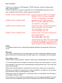
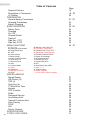
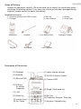
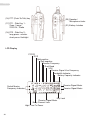
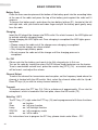
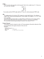
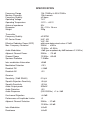
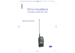
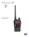
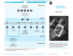
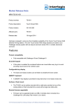
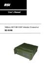
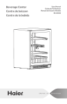
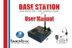
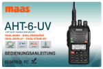
TeCom-DualBand
VHF & UHF
Handheld Transceiver
User’s Manual
Dear customer,
Thank you for buying a TEAM product. TEAM Electronic stands for high-quality
radio communication.
TeCom-DualBand is a unique combined UHF & VHFhandheld transceiver that is
easy to operate and it offers a wide range of functionality.
PR8056 TeCom-DualBand PMR/FreeNet : programmed with 8 PMR* & 6 FreeNet**
channels, 500 mW tx power, bandwidth
12.5 kHz, no registration or fees apply
PR8069 TeCom-DualBand PMR
PR5058 TeCom-DualBand COM
PR8057 TeCom-DualBand HAM
: programmed with 8 PMR* channels,
500 mW tx power, bandwidth 12.5 kHz,
no registration or fees apply
: commercial radio; 128 channels programmable; registration and fees apply
VHF 136-174 MHz / max. 5 W
UHF 403-480 MHz / max. 4 W
: amateur radio; 128 channels programma
ble; licence required
VHF 144-146 Mhz / max. 5 W
UHF 430-440 MHz / max. 4 W
manual frequency mode (VFO) and storage
of manually set frequency, as well as setup
of step size, bandwidth, repeater shift, txpower, beside the other available functions
Safety
It is important that the user understands hazards related to the operation of any transceiver.
Warning!
Turn off your transceiver prior to entering any area with a potentially explosive atmosphere (where the air contains gas, dust and smog, etc.), e.g. gasoline service stations.
Precautions in Use
Please follow the instructions to avoid fire, bodily injury and damage of the transceiver.
It is recommended not to exceed the maximum duration for transmission (1 minute)
and reception (4 minutes) since these operation tasks generate heat. Too much heat
may cause damage.
Please do not disassemble or assemble the transceiver under any circumstances.
Please do not expose the transceiver to direct sunlight for a long time; do not place
the transceiver near any heating devices, either.
Please do not put the transceiver in extremely dusty or moist places; do not place it
on unstable surfaces, either.
If the transceiver emits smoke or strange odors, turn it off, remove the battery from the
transceiver and immediately contact your authorized, local TEAM Electronic dealer.
English
Scope of Delivery
Description of Transceiver
LC Display
PREPARATION
General Battery Precautions
Charging Precautions
Battery Charging
BASIC OPERATION
Battery Pack
Charging
On / Off
Channel Select
Transmit
Side Key 1 PF1
Side Key 2 PF2
MENU FUNCTIONS
01 Step Size
03 Batterypack Savemode°
05 Roger Beep Tone
07 VOX
09 Voice Prompt
11 Beep Prompt
13 Busy Channel Lockout
15 Receiving CTC
17 Receiving DCS
19 Scan
21 Channel Mode
23 Offset°
25 Stopwatch
27 Memory Channels°
29 Reset
18
MISCELLANEOUS
Speed Search
A/B Switch (12)
TDR (4)
Scan Key (6)
1750Hz Burst Tone
Keylock
SOS Function
Radio
Password Security
Low Battery Alert
Transmit Overtime Alert
Wire Cloning
DTMF
ANI
Priority Channel
SPECIFICATIONS
CTCSS / DCS CODES
Table of Contents
02 Squelch Level (SQL-LE)
04 TX-Power° (Low/High)
06 Transmit Over Time (TOT)
08 Bandwidth° (Wide/Narrow)
10 Transmit Overtime Alarm
12 Power On Message
14 Automatic Keylock
16 Transmitting CTC
18 Transmitting DCS
20 PF1
22 Auto Back Light (ABR)
24 Shift (+ / -)°
26 Channel Name
28 Delete Channel°
° = nur in HAM Version verfügbar
Page
19
19 - 20
20
21 - 22
23
23
24 - 25
24
24
24
24
24
24
25
25 - 27
27
27
27
28
28
28
28
28
28
29
29
29
29
29
29
30
31
English
Scope of Delivery
Unpack the equipment carefully. We recommend you to identify the listed items before
discarding the packing material. If any items are missing or have been damaged during
shipment, please contact the dealer immediately.
Supplied Accessories
1 x Antenna (attached with PMR version)
1 x Charger
Transceiver
Beltclip
Antenna
Wrist Band
1 x Belt clip
1 x User's Manual
Li Ion Battery Pack
1 x Battery
1 x Hand strap
Intelligent Charger
User’s Manual
Description of Transceiver
(15) Flashligh
(1) rotary channel selector
(13) Receive-LED
(3) Transmit-LED
(12) A/B key
for Master
Frequency
(4) Single / Dual band key
(14) Antenna
(11) LCD
(10) Menu key
(9) numeric keys
(8) Up / Down
(2) On/Off & Volume Control
(5) Exit key
(6) Frequency Reverse / Scan key
(7) Keylock / Stopwatch key
19
English
(16) PTT (Push-To-Talk) key
(20) Speaker /
Microphone Jacks
(17) PF1 - Side Key 1 :
Scan / Lamp /
SOS-CH / Radio
(21) Battery Latches
(18) PF2 - Side Key 2 :
long press : monitor
short press: flashlight
LCD Display
CTCSS
DCS
Split positive
Split negative
Reverse Frequency
Dual Band
VOX
Receive Signal Vice Frequency
Bandwidth Indicator
Battery Capacity Indicator
Switch Master
Frequency Indicator
Receive Signal-Meter
Receive Signal-Meter
Key Lock
Receive Signal-Meter
Busy Channel Lock
High / Low Tx-Power
20
General Battery Precautions
PREPARATION
English
CAUTION
- Do not attempt to charge a fully charged battery pack. Doing so, may shorten the lifetime of the battery pack or the battery pack may get damaged.
- Upon completion of charging process, disconnect the battery pack from the charger.
If the charger power is reset (turned ON after being turned OFF), recharging will start
again and the battery pack will be over-charged.
- Do not use the transceiver while charging the battery pack. We recommend to switch
the transceiver power OFF during charging.
- Do not expose the battery pack to heat or fire.
- Never attempt to remove the casing from the battery pack.
DANGER!
- Do not disassemble or reconstruct the battery pack!
The battery pack has a safety function and protection circuit to avoid danger. If they
suffer serious damage, the battery may generate heat or smoke, rupture, or burst into
flame.
- Do not short-circuit the battery!
Do not join the + and - terminals using any form of metal (such as a paperclip or wire).
Do not carry or store the battery pack in containers holding metal objects (such as
wires, chain-necklace or hairpins). If the battery pack is short-circuited, excessive current will flow and the battery may generate heat or smoke, rupture, or burst into flame.
It will also cause metal object to heat up.
- Do not apply heat to the battery!
If the insulator is melted, the gas release vent or safety function is damaged, or the
electrolyte is ignited, the battery may generate heat or smoke, rupture, or burst into
flame.
- Do not place the battery near fires, stoves, or other heat sources!
If the polymer separator melts due to high temperature, an internal short-circuit may
occur in the individual cells and the battery may generate heat or smoke, rupture, or
burst into flame.
- Do not immerse the battery in water or get it wet by other means!
If the battery's protection circuit is damaged, the battery may charge at extreme current (or voltage) and an abnormal chemical reaction may occur. The battery may generate heat or smoke, rupture, or burst into flame.
- Do not charge the battery near fires or under direct sunlight!
If the battery's protection circuit is damaged, the battery may charge at extreme current (or voltage) and an abnormal chemical reaction may occur. The battery may generate heat or smoke, rupture, or burst into flame.
- Use only the specified charger and observe charging requirements!
If the battery is charged in unspecified conditions (under high temperature over the
regulated value, excessive high voltage or current over regulated value, or with a
remodeled charger), it may overcharge or an abnormal chemical reaction may occur.
The battery may generate heat or smoke, or burst into flame.
21
English
- Do not pierce or strike the battery with any object or step on it!
This may break or deform the battery, causing a short circuit. The battery may generate heat or smoke, rupture, or burst into flame.
- Do not jar or throw the battery!
An impact may cause the battery to leak, generate heat or smoke, rupture, and/or
burst into flame. If the battery's protection circuit is damaged, the battery may charge
at an abnormal current (or voltage), and an abnormal chemical reaction may occur.
The battery may generate heat or smoke, rupture, or burst into flame.
- Do not use the battery pack if it is damaged in any way!
The battery may generate heat or smoke, rupture, or burst into flame.
Do not solder directly onto the battery!
If the insulator is melted or the gas release vent or safety function is damaged, the
battery may generate heat or smoke, rupture, or burst into flame.
- Do not reverse the battery polarity (and terminals)!
When charging a reversed battery, an abnormal chemical reaction may occur. In
some cases, an unexpected large amount of current may flow upon discharging. The
battery may generate heat or smoke, rupture, or burst into flame.
- Do not reverse-charge or reverse-connect the battery!
The battery pack has positive and negative poles. If the battery pack does not
smoothly connect with a charger or operating equipment, do not force it; check the
polarity of the battery. If the battery pack is reverse-connected to the charger, it will
be reverse-charged and an abnormal chemical reaction may occur. The battery may
generate heat or smoke, rupture, or burst into flame.
- Do not touch a ruptured and leaking battery!
If the electrolyte liquid from the battery gets into your eyes, wash your eyes out with
fresh water as soon as possible, without rubbing your eyes. Go to the hospital immediately. If left untreated, it may cause eye-problems.
WARNING
- Do not charge the battery for longer than the specified time!
If the battery pack has not finished charging even after the regulated time has passed,
stop the charging process. The battery may generate heat or smoke, rupture, or burst
into flame.
- Do not place the battery pack into a microwave or high pressure container!
The battery may generate heat or smoke, rupture, or burst into flame.
- Keep ruptured and leaking battery packs away from fire!
If the battery pack is leaking (or the battery emits a bad odor), immediately remove it
from flammable areas. Electrolyte leaking from battery can easily catch on fire and
cause the battery to generate smoke or burst into flame.
- Do not use an abnormal battery!
If the battery pack emits a bad odor, appears to have different coloring, is deformed, or
seems abnormal for any other reason, remove it from the charger or operating equipment
and do not use it. The battery may generate heat or smoke, rupture, or burst into flame.
22
English
Charging Precautions
The transceiver is equipped with a TEAM Li-Ion battery pack (7.4 V / 1300 mAh). The
following tips help you to obtain the best battery performance and a prolonged battery
life.
- Charge the new battery pack continuously for 4~5 hours before its initial using, which
ensures the maximum battery capacity and best performance in using.
- Do not attempt to charge the TEAM battery pack in any other charger than the one
included in the scope of delivery.
- The battery pack can be charged while in the transceiver, and to ensure it is fully
charged it's recommended to charge the battery pack with the transceiver turned off.
- The ideal temperature to store the battery pack is 25 °C (room temperature). Charging
the battery pack at a low temperature (below 0°C) will cause electrolyte leakage and
damage to the battery pack.
- Charging the battery pack at a high temperature (above 35 °C ) will cause decrease
in battery discharge capacity and affect the transceiver performance.
- The new or used battery should be stored in a cool and dry place.
- If recharge the battery pack after long storage, you should charge it continuously for
4~5 hours.
- Do not leave the transceiver and the battery in the charger when not charging. Overcharging will shorten the battery’s life. Do not use the charger as a base station.
- After the battery life expires, the Li-Ion battery pack has to be recycled appropriately.
Battery Charging
A new battery, or a battery with low power level needs to be charged completely.
Red LED
- Red The battery is in the state of charging.
Green LED - Green The battery is fully charged
1) Plug the adapter into an AC wall outlet. The LED will light red for a short time before
it turns off. Now, the charger is ready to be used.
2) Place the battery or transceiver into the charger slot. The LED starts blinking every two
seconds. Charging time depends on battery capacity. When battery is fully charged, the
LED turns green.
Notes:
1) The battery is not fully charged in the factory.
Before the initial use, please charge the new battery continuously for 4~5 hours.
2) The charger will stop charging and the left, red LED will go off. If the charger detects
a damaged battery or if the temperature of the battery is too high, then the right LED
will light yellow.
3) The charger detects if the battery is fully charged and stops charging.
23
English
BASIC OPERATION
Battery Pack
Place the three counter-pieces at the bottom of the battery pack into the according holes
at the rear of the radio and press the top of the battery pack against the radio until it
snaps in.
To remove the battery pack, push down the two battery latches (21), located at the left
and right side, with your thumb and index finger and pull the battery pack gently away
from the radio.
Charging
Insert the AC plug of the charger into 220V outlet. For a brief moment, the LED lights red
to indicate stand-by charging mode.
During charging the LED lights red. Once charging is completed the LED lights green.
Important:
> Please remove the radio out of the charger once charging is completed.
> Do not use the charger as a base station.
> Only charge empty battery packs.
> Do not remove the radio out of the charger until the charging process is
completed.
On / Off
Please note that the battery pack needs to be fully charged prior to first use.
Turn on the radio by turning the rotary On/Off-Volume knob clockwise over the barrier.
To set a comfortable volume level, press the monitor key [PF2 ] (18) - a constant noise
will be heard - and adjust the volume.
Channel Select
To select the channel for transmission and reception, set the frequency band where the
channel is located with the A/B switch. Next, select the channel either with the Up /
Down keys (8) or with the rotary channel selector (1).
Transmit
To transmit press the PTT key (16). Talk in a distance of approximately 10 cm into the
microphone, which is located on the front plate, above the A/B switch (12).
Side Key 1 PF1
The PF1 key (17), right under the PTT key (16) can be programmed with these functions:
Off
Scan
Lamp
SOS-CH
radio
:
:
:
:
:
no
on
on
on
on
function
/ off scan function
/ off flashlight function
/ off emergency mode
/ off fm-radio
For instructions how to program the PF1 key, please check under Menu - PF1.
24
English
Side Key 2 PF2
The PF2 key (18), located under the PF1 key (16), is a dual-function key that is pre-programmed with the flashlight function and the monitor function.
To turn the flashlight on / off, press the PF2 key shortly.
To acitvate the monitor function, press the PF2 key long. After one second the monitor
function starts and will be active as long as the PF2 key is pressed.
25
English
MENU
1. Enter the menu by pressing the MENU key (10).
2. Select the function by turning the channel selector or by entering the function
number via the number keypad.
3. Access the selected functions parameter by pressing the MENU key (10) and set
the parameter with the or key (8).
4. Confirm your selection by pressing the MENU key (10) again.
5. To return to StandyBy press the EXIT key (5).
01 Step Size
02 Squelch Level (SQL-LE)
03 Batterypack Savemode
04 TX-Power° (Low / High)
05 Roger Beep Tone
06 Transmit Over Time (TOT)
07 VOX
08 Bandwidth° (Wide/Narrow)
09 Voice Prompt
10 Transmit Overtime Alarm
11 Beep Prompt
12 Power On Message
.
26
13 Busy Channel Lockout
Step Size (STEP)
Only available in the HAM version
5 / 6.25 /10 / 12.5 / 25 / 50 / 100 kHz
Squelch levels 0 - 9
0 = squelch open, receives all signals
9 = squelch opens on very strong signals
On / Off
Tx Power (TXP)
Only available in the HAM version
HIGH = high tx power /
LOW = low tx power
Voice Prompt : OFF / BOT* / EOT° / Both
OFF / 15 - 600 s in 15-second-steps
Transmission aborted after expired time;
release PTT for reset
OFF / level 1 - 9 (1 = least sensitive)
Voice operated transmission;
Bandwidth (WN)
Only available in the HAM version
WIDE = 25 kHz / NARR = 12,5 kHz
OFF / English
prompts in english language
OFF / 1 - 9 s
warns prior to expiration of TOT
ON / OFF - warn tone
OFF / BATT / MSG
OFF
: displays full display
BATT : displays current voltage level
MSG : displays TEAM Welcome
ON / OFF
No transmission on busy channels
* Beginning of Transmission; Upon pressing PTT key
° End of Transmission; Upon release of PTT key
English
14 Automatic Keylock
15 Receiving CTC
16 Transmitting CTC
17 Receiving DCS
18 Transmitting DCS
19 Scan
20 PF1
21 Channel Mode
22 Auto Back Light (ABR)
23 Offset°
24 Shift (+ / -)°
ON / OFF
If no function key is pressed within 15 s, the keylock function is automatically activated. The key
symbol appears in the right, lower corner of the
display.
The stopwatch function (25) has to be set off
OFF / 50 CTCSS codes
select one out of 50 DCS codes for receiving
frequencies; 67 kHz - 254.1 kHz
OFF / 50 CTCSS codes
select one out of 50 DCS codes for transmitting
frequencies; 67 kHz - 254.1 kHz
OFF / 105 DCS codes
select one out of 105 DCS codes for receiving
frequencies; DO23N / I - DO754N / I
OFF / 105 DCS codes
select one out of 105 DCS codes for transmitting
frequencies; DO23N / I - DO754N / I
TO (Time Scanning - pauses scanning upon reception of signal and continous scanning
after 5 s of no operation)
CO (Carrier Mode 1 - pauses scanning once
signal is received and continous scanning
after 3 s of disappearance of signal) /
SE (Carrier Mode 2 - scanning stops once signal
is received)
SCAN / LAMP / SOS-CH / RADIO / OFF
select one available functions
select display mode
CH
(displays channel no.)
CH FREQ (displays channel frequency)
NAME
(displays channel name)
ON / OFF
Frequency Shift (0 - 69,950 MHz)
Only available in the HAM version
Enter the frequency shift via the Up / Down (8) keys or the rotary channel selector ().
Frequency Shift High / Low
Only available in the HAM version
- determines if in function 23 (offset) set frequency offset is shifted above (+) or below (-) the
transmitting frequency. The according symbol
(+, -) appears in the display.
27
English
25 Stopwatch
26 Channel Name
27 Memory Channels (MEM-CH)
28 Delete Channel (DEL-CH)
29 Reset
28
ON / OFF - press key keylock (7) to start, press
any key to stop function
max. 6 digits composed of letters (A-Z),
numbers (0-9) and signs (?, +, -); select digits
with up key (8) or by turning channel selector
clockwise. To switch cursor to the next digit, turn
channel selector counter-clockwise
in VFO-Mode (only HAM version):
to store manually set frequencies
in channel mode: to copy pre-programmed
frequencies :
1. Select the channel to be stored.
2. Press the menu key (10) and select the
function 27 MEM-CH.
3. Press the menu key (10) and select a channel
where the selected frequency is to be stored.
4. Press the menu key (10) to confirm the selection
Comes handy when using different CTCSS/DCS
codes for one frequency.
This function is only available in the HAM version.
In VFO mode, manually stored frequencies are to
be deleted with this function
1. Press the menu key (10) and select the
function 28 Delete Channel (DEL-CH).
2. Press the menu key (10) and select the channel to be deleted with the channel selection Up
/ Down keys (8).
3. Press the menu key (10) and select the
the function 28 Delete Channel (DEL-CH).
For reset to default settings:
1. press menu key (10) & select RESET function 29
2. press menu key (10) & select ALL
3. press menu key (10) & enter password if
programmed in software;
Display shows WAIT. Reset is performed, menu
is exited and radio automatically returns to basic
operation.
English
MISCELLANEOUS
Speed Search
Long press of the up or down key runs through the menu or channels at an accelerated speed.
A/B (12)
In single band mode, the A/B key (12) switches between the frequency bands UHF and VHF.
In dual band mode there are two frequencies displayed. Use the A/B key to determine
master- and vice frequency. Master frequency is for reception and transmission - on vice
frequency only reception is possible.
Is a signal received on vice frequency, the letter S appears in the upper right side of the
display. Selection of the master frequency is done by the A/B key (12), indicated by a
black arrow on the left side of the display.
TDR (4)
Switch between single / dual band display. By default, the dual band display is activated.
To switch to the single band display press the TDR key. In single mode display, always
the master frequency is set. To change the master frequency switch to dual band display, and set the master frequency with the A/B key - the arrow on the left side indicates
the master frequency.
Scan Key (6)
The Scan key (6) is a dual-function key that controls the functions Frequency-Reverse
and Scan.
The Frequency-Reverse function is only usable for the COM version that permits different frequencies for transmitting and reception. When pressing the Scan key shortly,
transmitting and reception frequencies are reversed. The letter R, in the upper row of
the the display, indicates the activated status of the Frequency-Reverse function.
To activate the Scan function, press the key for a longer period of time. The letter R
appears and disappears, then the scan function starts.
1750Hz Burst Tone
To send 1750 Hz tone for repeater operation, press PTT (16) and PF1 (17) at the same time .
Keylock
Press the keylock key (7) for approximately one second to activate / deactivate the keylock function. All keys will be locked except for PTT, monitor and volume.
SOS Function
An SOS signal is transmitted on the actual channel of the selected band (A or B) while on
the transmitting radio the SOS signal is audible and the flashlight blinks. The SOS cycle
will be active for 10 seconds every 5 minutes. To abort the actual cycle press any key.
29
English
Radio
Scan the radio frequency band (76 - 108 MHz) by pressing the scan key (6). The scan
function will stop automatically on an occupied radio station.
To manually set the radio frequency, use the channel selector knob.
A maximum of eighteen radio frequencies can be stored in two banks. To store a radio
station follow these steps:
1. Turn on the radio.
2. Set radio station to be stored either manually or via scan function.
3. Select the desired bank (TEAM1 or TEAM2) where the station is to be stored by
pressing the keylock button (7), e.g. TEAM2.
4. Press Menu key (10) - the display shows Save?
5. Press memory space 1 - 9 to store radio station, e.g. press ROGER5.
To recall a stored radio channel:
1. Turn on the radio function
2. Select a bank by pressing the keylock key, e.g. TEAM2
3. Select a radio station by selecting a memory space, e.g. ROGER5.
The current frequency is still working while the radio is on. Upon reception of a signal,
the radio function pauses until the signal disappears. After five seconds the radio function continues. When pressing the PTT key, radio function is immediately paused and will
continue a few seconds after release of PTT key.
Password Security
For security reasons and to avoid unintended resets, a password can be set up via the
software T-UP14. For more details, see software manual.
Low Battery Alert
When the voltage of the battery pack drops below a critical level, the transceiver beeps
and the display flahses every 5 seconds.
Transmit Overtime Alert
When programmed transmit-over-time is expired, the transceiver will beep and transmission will stop. To start transmission again, release and press PTT again.
Wire Cloning
To wire-clone another TeCom-DualBand, the optional cloning-cable is required.
Connect the two radios via cloning-cable and press the MONI key (18) to start cloning.
Source-Radio
: LED flashes red during cloning and stops flashing after success
ful procedure. LED lights continously is case of cloning failure.
Target-Radio
: LED flashes green during cloning and stops flashing upon completed procedure.
30
DTMF
DTMF can be send manually via the keypad. Next to the number keys 0 - 9, there are
four more keys available:
MENU: A
:B
:C
EXIT : D
To manually send the DTMF code, hold the PTT key (10), while entering the DTMF code.
ANI
The radio contains the function ANI (automatic number identification). Via software, a
6-digit DTMF code can be programmed. For the codes, the symbols 0 - 9, A, B, C and
D are available.
The code can be send manually or automatically via PTT push. The receiver will be
able to see the ANI code of the transmitter, as long as this function is available.
For more details about programming this function, see manual T-UP14.
Priority Channel
Via software a priority channel can be set. During scanning, this priority channel will be
scanned between the regular channels of the scan list.
Example:
Priority Channel : 8
Scan List
: 1, 2, 3, 4
Scan
:1-8-2-8-3-8-4-8
31
Frequency Range
Memory Channels
Frequency Stability
Operating Voltage
Operating Temperature
Antenna Impedance
Dimension
Weight
Transmitter
Frequency Stability
RF Carrier Power
SPECIFICATION
136-174MHz & 400-470MHz
128 channels
±2.5ppm
7.4V
-30°C ~ +60°C
50W
58 × 105 × 38 mm
250g
Audio Modulation
±2.5PPM
UHF: 4W
VHF: 5W
within pre-determined value ±7.5dB
25KHz : ±5KHz
12.5KHz: ±2.5KHz
+3dB (pre-emphasis by 6dB between 0.3-3KHz)
Channel Space
Spurious Radiation
12.5KHz: ?60 dB
?-30dBm
Effective Radiation Power (ERP)
Max. Frequency Deviation
Adjacent Channel Power
Inter modulation Attenuation
25KHz : ?70 dB
Modulation Distortion
?40dB
Residual AM
£-35dB
Residual FM
Receiver
Sensitivity (12dB SINAD)
Squelch Rejection Sensitivity
Squelch Sensitivity
Audio Output power
Audio Distortion
Audio Response
Co-channel Rejection
Performance of Amplitude Limiter
£10%
£3%
0.16µV
£0.8µV
£0.2µV
500mW
£5%
(300-3000Hz) +1 to -3dB
?-8.0dB
Adjacent Channel Selection
£3
Inter-Modulation
?65 dB
Resistance
25KHz : ?70 dB
12.5KHz: ?60 dB
?84 dB
For sale and use in :
WEEE - Reg. Nr. DE 91930360 8 ( EAR ), 50635 ( ERA )
GRS-Nr. 10001374
DSD 2617305, ARA 2284