1
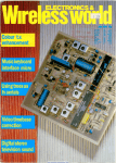
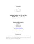
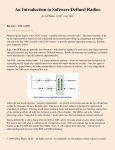
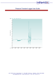
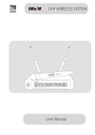
EQUIPMENT REVIEW
PETER HART, G3SJX ♦ E-MAIL: [email protected]
AUGUST 2009 ♦ RADCOM
FlexRadio FLEX-3000 HF
and 50MHz SDR Transceiver
INTRODUCTION. FlexRadio Systems has
recently added another transceiver to their
range of innovative software defined radios.
The FLEX-3000 is a new model, smaller and
lower in cost compared to the FLEX-5000A
that was reviewed in the January 2008
and March 2009 issues of RadCom. The
FLEX-3000 received CE certification in May
and first deliveries to Europe started in June.
With a footprint and height similar to a laptop
PC, it uses the same architecture as the
FLEX-5000A and feature set provided by
the same PowerSDR software.
24
COMPARISON WITH FLEX-5000A. The
FLEX-5000A uses a modular construction
with plenty of space to add additional boards
such as an ATU, second receiver and transverter.
The FLEX-3000 uses two PCBs mounted on
a flat bottom plate with no provision for
expansion. A single hardware receiver is
accommodated but the PowerSDR software
allows for two separate and isolated receive
channels within a 96kHz receive window. No
duplex, cross-band or cross-mode operation is
possible. The FLEX-3000 does, however,
include a built-in auto ATU that is only
selectable if the antenna match is poor. There
is a single antenna socket (BNC connector),
no provision for separate receiver antenna
and the audio line input/output and switching
interfaces are more limited for the FLEX3000. However,
the receiver frequency range and transmit
output power are the same. The panadaptor
spectrum display is limited to 96kHz and
the front-end filtering in the FLEX-3000 is
significantly reduced. The claimed dynamic
range figures are lower than for the FLEX5000A, probably because a lower specified
ADC is used, but the cost is considerably less.
SYSTEM HARDWARE. The FLEX-3000 is
used in conjunction with a PC and a Firewire
bus provides all control for the hardware
and the digitised transmit and receive IF
paths. A sound card is not required in the
PC. The receiver tunes from nominally
100kHz to 60MHz. Incoming signals are
down-converted to a low IF using a pair of
quadrature sampling detectors as an image
rejection mixer. The IF is set by default to
9kHz but can be set by the software to be in
the range 0Hz to 20kHz. Image rejection is
the principal weakness with this architecture
although software trimming reduces the
image to quite low levels. A spur reduction
mode is provided that allows the IF to vary
between about 9 and 16.6kHz, coarse
stepping the DDS in 7.6kHz steps and fine
tuning by the DSP at the IF. This moves the
image frequency and hopefully helps when
image or other spurs are a problem. The
resulting I and Q outputs from the mixers
are fed to 24-bit A/D converters and thence
to the PC for all signal processing. Local
oscillator drive in quadrature to the two
mixers is obtained directly from a high
frequency Direct Digital Synthesiser (DDS)
IC tuning in 1Hz steps. The receiver front-end
uses 5th order bandpass filters (7th order
on 160m) and a total of seven filters covers
the tuning range of the radio. In comparison,
the FLEX-5000 uses higher performance
11th order filters, one for each amateur
band. A nominal 26dB gain front-end
preamplifier can be selected on bands
above 160m, or a 20dB front-end attenuator
for very strong signals.
On transmit, a similar pair of quadrature
mixers and DDS is used to up-convert the
quadrature transmit signal from the PC via
the Firewire bus and on-board 24-bit D/A
converters to give the transmit signal source.
This is then amplified using power MOSFET
transistors and low-pass filtered to give the
required 100W output power. An auto ATU
is built in, using relay-switched inductors
and capacitors.
The radio is powered from an external
13.8V power supply, drawing up to 25A
on transmit. The circuitry is contained on
two printed circuit boards mounted on a
base plate and a thin heatsink is blown
by two fans which are quite noisy,
particularly on transmit. This assembly
fits into a wrap-around case measuring
311mm (w) x 44mm (h) x 311mm (d).
The only controls on the front panel are
the illuminated on/off switch, headphone
jack, RJ-45 microphone socket (Yaesu
compatible pinning) and CW key jack.
The rear panel contains a BNC antenna
socket, PTT input, TX grounded output,
audio line in (via FlexWire socket) and
audio line out. Computer style powered
speakers can be connected to the audio
line out socket. The 9-pin D connector
FlexWire interface provides control for a
future range of accessories using I2C bus
control. The Firewire computer interface
uses the IEEE1394a 400Mb/s standard
and not the higher speed 1394b standard.
SYSTEM SOFTWARE. Apart from the
hardware functions already described, the
remaining features and functions of the
radio are defined largely by the PowerSDR
software, which runs on the PC. This
software is common to the FLEX-5000
and hence both radios share the same
user interface and software-related feature
set. PowerSDR is constantly being developed
and improved as freely available GPL open
source code. Code updates are quite frequent
and are released via the FlexRadio website
at www.flex-radio.com. The feature set is
quite awesome, there are probably more
features and functions than any other top
end radio currently available. The core feature
set was described in the FLEX-5000A review
in the January 2008 RadCom and will not
be repeated here but a full description of all
the features is included in the FLEX-3000
user manual, which runs to nearly 200
pages. Paper manuals are not included with
the radio, except for a quick start guide. All
files and manuals are provided on CDROM
RADCOM ♦ AUGUST 2009
but the latest versions of all are readily
downloadable from the FlexRadio website.
The first step to getting the radio up and
running is to install the driver and system
firmware either from the supplied CDROM
or from the FlexRadio website. All software
is compatible with Windows Vista and XP
operating systems. The next step is to install
the PowerSDR software and then finally
a few configuration set-ups. The whole
process takes about 10 minutes. The radio
is supplied fully calibrated, including image
nulling, although this can be optimised with
some care.
FlexRadio have completed an adaptive
nulling routine termed ‘Wide Band Image
Rejection’ or WBIR and this was demonstrated
at Dayton this year. This will reduce images
down to the noise floor automatically as
the frequency is changed and will be issued
this summer.
A fast PC is a definite advantage as it
minimises time delays (latency) and enables
additional applications such as RTTY or PSK
to be used via the Virtual Audio Cable without
problems. A Firewire IEE1394 interface is
of course required and the radio is provided
with a 6 pin lead. A 6-pin to 4-pin adaptor
or separate lead will be needed with laptop
computers where this smaller socket is fitted.
I used my Dell laptop PC with a 1.3GHz
Celeron M processor, which is quite old now,
with generally satisfactory results, but a faster
PC would be better.
MEASUREMENTS. The measured
performance is shown in the table. The
preamplifier gain is some 10dB higher than
the FLEX-5000A and although the sensitivity
is similar with the preamplifier off, it is
significantly better than the FLEX-5000A
with the preamplifier on. The sensitivity
EQUIPMENT REVIEW
than measured for the FLEX-5000A. I was
drops rapidly at
unable to measure intermodulation limited
lower frequencies
dynamic range and third order intercept as
below 500kHz
reciprocal mixing noise dominated and at
and is not really
higher levels ADC overload occurred.
usable at LF.
Similarly, blocking could not be measured
Additional frontbut I had the impression that the front-end
end bandpass
had good strong signal performance. Inband
filters are needed
distortion levels are extremely low and this
for MF broadcast
makes for a very clean sounding receiver.
reception to
Transmit intermodulation products on
suppress images
SSB were generally reasonable on the middle
and harmonic
breakthrough. The bands but poor on the low and high bands.
It is important to set the microphone gain
image rejection at
correctly. A helpful TX mic meter setting is
18kHz below the
provided for this purpose. The CW keying
receive frequency
envelope was clean and well shaped with
varied across the
negligible character shortening. A delay
bands from 44dB
of about 40ms resulted with my laptop, it
to 69dB with the
should be shorter with a faster PC. This
factory default
delay is about half of that measured with
calibration, which
falls rather short of the FLEX-5000A and an earlier version
of PowerSDR.
the published
specification of
ON-THE-AIR PERFORMANCE. As might be
70dB. It is
expected, the overall operating experience
possible, with some degree of effort, to null
was similar to the FLEX-5000A. I found
out the image to over 70dB but the settings
the on-air performance of the radio very
do not hold over the band (but see comment
impressive. The receiver sounded very
in the Conclusions). Switching-style mixers
respond to harmonic frequencies. Rejection of clean and low noise. The audio quality is
excellent and the filter arrangements are
2nd and 3rd harmonics was typically some
really effective. There is no click when the
70 to 90dB (worst case 65dB). The higher
order filters used in the FLEX-5000
remove any harmonic response
FLEXRADIO SYSTEMS FLEX-3000 MEASURED
entirely. A number of weak spurious
PERFORMANCE
signals or birdies were audible on
RECEIVER MEASUREMENTS
most bands and visible on the
---SENSITIVITY SSB 10dBs+n:n--spectrum display but, to be fair,
FREQUENCY PREAMP IN
PREAMP OUT
these were largely below band noise
1.8MHz
1.1µV (-106dBm)
3.5MHz
0.70µV (-110dBm) 1.1µV (-106dBm)
level except on the quieter higher
5MHz
0.28µV (-118dBm) 1.0µV (-107dBm)
frequency bands.
7MHz
0.16µV (-123dBm) 1.0µV (-107dBm)
10MHz
0.16µV (-123dBm) 1.3µV (-105dBm)
The S-meter showed a very linear
14MHz
0.13µV (-125dBm) 1.0µV (-107dBm)
indication with 50µV for S9 and 6dB
18MHz
0.13µV (-125dBm) 1.4µV (-104dBm)
per S unit. The display indicates
21MHz
0.13µV (-125dBm) 1.3µV (-105dBm)
24MHz
0.11µV (-126dBm) 1.4µV (-104dBm)
signal input in dBm with an excellent
28MHz
0.14µV (-124dBm) 2.2µV (-100dBm)
accuracy of about ±2dB. The AGC
50MHz
0.13µV (-125dBm) 2.8µV (-98dBm)
attack characteristic interrupts the
AM sensitivity (28MHz): 0.7µV for 10dBs+n:n at 30% mod FM
signal for 5 to 10ms change to and
sensitivity (28MHz): 0.16µV for 12dB SINAD 3kHz pk dev
Inband intermodulation products: <-50dB
can impair readability of weak
signals under noisy conditions.
TRANSMITTER MEASUREMENTS
I have seen this effect on a number
---CW---INTERMODULATION
of IF DSP radios. Channel selectivity
-POWER------PRODUCTS-----FREQUENCY OUTPUT HARMONICS 3rd order 5th order
measurements were not made as
1.8MHz
95W
-55dB
-25dB
-39dB
this is determined by the PowerSDR
3.5MHz
97W
-50dB
-24dB
-38dB
software and will be the same as for
7MHz
100W
-68dB
-30dB
-36dB
10MHz
99W
-57dB
-34dB
-34dB
the FLEX-5000A.
14MHz
99W
-58dB
-38dB
-36dB
Reciprocal mixing measurements
18MHz
100W
-54dB
-41dB
-38dB
were independent of frequency
21MHz
106W
-64dB
-34dB
-36dB
24MHz
986W
-57dB
-29dB
-36dB
spacings from 1kHz out to beyond
28MHz
102W
-66dB
-26dB
-36dB
300kHz. On 21MHz this yielded a
50MHz
98W
-59dB
-22dB
-38dB
phase noise limited dynamic range of
Intermodulation product levels are quoted with respect to PEP.
87dB in 2.1kHz bandwidth (93dB in
Sideband and carrier suppression: 60dB
500Hz bandwidth or –120dBC/Hz).
Transmitter AF distortion: much less than 1%
Microphone input sensitivity: 0.2mV to 30mV for full output
The performance degraded at the
NOTE: All signal input voltages given as PD across antenna
lower frequencies and on 1.8MHz
terminal. Unless stated otherwise, all measurements made on
was 9dB worse. These results are
USB with 2.1kHz bandwidth filter selected.
rather poor and some 5 to 9dB worse
25
EQUIPMENT REVIEW
AUGUST 2009 ♦ RADCOM
The audio quality on transmit using a
Heil Handi Mic HM-5 was excellent, and
CW effective but the fans seemed very noisy.
It is a matter of personal preference how
you view the computer keyboard as your sole
interface to your radio. Some feel it is the way
forward, highly flexible and features such as
point and click tuning enable rapid frequency
navigation. Others, including myself, prefer
the traditional approach with round knobs,
switches and a good tuning dial.
headphones are connected: this problem
with the FLEX-5000A has been fixed. The
panadaptor display adds another dimension
to tuning and keeps you aware of signals on
adjacent channels. DSP noise reduction,
noise blanking and other receiver features all
worked very well indeed. I did not experience
FEATURE
any problems due to intermodulation or
overload but images could be heard from
strong broadcasters and strong amateur
stations. The ability to receive on two
channels simultaneously in stereo within
the IF band was excellent, just what is
needed for DX split frequency working.
WEBSEARCH
FlexRadio Systems: www.flex-radio.com
ELAINE RICHARDS, G4LFM ♦ E-MAIL: [email protected]
Gerald Youngblood,
the name behind
FlexRadio
INTERVIEW. At Dayton Hamvention this year,
I was fortunate to have a chat with Gerald
Youngblood, the man behind FlexRadio.
26
CONCLUSIONS. The FLEX-3000 with
PowerSDR software is a most impressive
radio. Although some aspects of performance
are not as good as the FLEX-5000A, it is
nevertheless an excellent performer and a
significant price saving over its larger brother.
There has been a substantial price increase
over the last year on many US products.
The FLEX-3000 is priced at £1395 inc
VAT, almost half the current price of the
FLEX-5000A with ATU.
My thanks to Waters and Stanton PLC
for the loan of the radio.
You were interested in amateur radio at a
young age, when were you first licensed?
I got my licence in 1967 when I was a
teenager in high school around the age of 15
or 16. Somebody gave me an old military
surplus radio. It was about two feet long
and so full of parts you couldn’t lift it. I was
fascinated. I took every part out of it and
sorted it. I didn’t know what the parts were
but I was fascinated by the electronics in it.
A friend of mine in ninth grade got his ham
licence and had a Hammarlund receiver and
some home-brew kit. I started working
toward a licence when we moved to a new
town and I found an ‘Elmer’. I moved to this
small town that had something called a two
year college. The physics teacher in the
college took me under his wing and taught
me about ham radio. I bought a Hallicrafters
S38 receiver – I think I paid something like
$30 for it – and my teacher helped me build a
6L6 transmitter and I got my Novice licence. I
got on the air and worked 80m and 75m and
made a lot of friends doing that. That was
probably tenth grade and so, through that, I
became interested in electrical engineering.
So did amateur radio set you off on a career?
Definitely. Because of ham radio I got
interested in the technical side of radio and
built amplifiers and things like that. I went
on to get an electrical engineering degree.
I stayed active in amateur radio until my
sophomore year in college. At that point
school took over and so I really didn’t do
much with it, although I kept my licence.
AUGUST 2009 ♦ RADCOM
I got involved in broadcast engineering
whilst at college and I entered a co-operative
engineering programme with a UHF television
station that was being built from the ground
up, where I would work a semester and go to
school a semester. So, actually, whilst I was in
school, I helped as an engineer to build a
UHF television station. So I got to work with
klystrons and all kinds of other stuff – very
hands on. My boss at the TV station was a
ham and he was the one who got me the job
as a co-op student.
What drew you to software defined radio?
When I was studying electrical engineering I
had the option to take different things like
power engineering, communications or
digital. I took the communications path.
So in my senior year I took the theory of
communications engineering, which included
how you modulate signals, demodulators,
fast Fourier transforms and all the basic math
and things that are in digital signal processing.
At that time we used punch cards to program
computers. You didn’t do a lot of fast Fourier
transforms with punch cards! But the theory
was there. So that’s where I started.
I began my career in the business side of
technology. I’m an entrepreneur. So I started
companies, raised venture capital funding,
even took a company public on the NASDAQ
in the mid 90s during the internet boom.
FEATURE
AUGUST 2009 ♦ RADCOM
Law and analogue to digital converters were
getting better. It took me about three or four
years – I don’t know the exact time period.
I probably started in 1999 and completed
the first unit in 2003. It took me that long
because I basically had to go back to school,
using the internet.
28
So I was in the business side of things, the
technology side was more in the concept
– system level, working with engineers to
define what we were going to do as a
business – so I didn’t get to play with the
technology like I did in the early days.
About 10 years ago, my son, who was
14 at the time, got interested in ham radio.
So I worked with his to get his licence – I
think he just wanted to do something with
Dad. I got re-interested and found that a lot
had changed with technology and radio
during that time. One of the things that
happened was PSK 31 came along. I plugged
in the radio to the sound card of my PC and I
worked somebody in the Ukraine that I
couldn’t hear and I said, “this is amazing”. I
remembered the theory from my senior year
at college about in phase and quadrature
signals and being able to modulate and
demodulate anything. I had had a Central
Electronics 28 phasing exciter when I was in
high school, which is a direct up-conversion
exciter: it’s a phasing exciter and so it used
the same theory. There were problems with
that in those days because of the analogue
components. Well, in the digital world you
can solve those problems because you have
mathematical precision that you don’t get in
the analogue components that vary and drift.
And so I put those together and said I have a
sound card in my computer that has a left
and a right channel input, stereo input, and if
I need to bring an I and Q input into that
soundcard I can build some hardware that
converts it to I and Q. The theory to do that
was in the handbook – the R2 receiver is an
example of that. In the software I could
correct those problems you have in the
hardware and I could take a PC and build a
radio around the PC. That was the concept.
I hadn’t done engineering since the late
70s. I didn’t realise how hard it was going
to be. I had to go and learn digital signal
processing, which I had the basics for but
things had moved on quite a bit. Now instead
of doing punch cards you could do it realtime, that was the difference, I could do a fast
Fourier transform in real-time. PCs were
getting faster and faster according to Moore’s
Did you see this as another business at the
time?
No. This was purely a hobby, just to see if
my brain worked. I love the technology but
was a frustrated engineer as I’d been doing
the business side and hadn’t been able to do
the technology in all those years. It was really
to see if I could do the technology. I had to go
and learn all these things like digital signal
processing, how to do RF down conversion,
Visual Basic and so on. I effectively had to
put myself back through college and learn
all these disciplines – just for fun! It was so
hard to dig out the digital signal processing
because all the books were written for
mathematicians, which I’m not. They wrote
as if you were going to create an FFT rather
than use one. There’s a difference between
creating it and using it.
What I wanted to do was write an article
and try to bring it down to earth of how you
could practically use it and so I proposed
something to QEX. I wrote a four article series
called Software Defined Radio for the Masses
over 2002/2003. By the third part I had
e-mails from all over the world saying ‘this
is really exciting, I haven’t been this excited
about ham radio since I started, would you
make a kit out of these boards you’re
developing because I’d like to play with them?’
So I thought about it. Now, I’ve started
businesses and I know how hard it is to
support a lot of customers, especially with
something that is prototype. So I said that I
would sell ten units. I put out an e-mail to,
maybe, 500 people that had written to me
asking them to tell me what their technical
background was, why they were competent
to use the boards and why they should get
one. That’s because I didn’t want to support a
lot of customers because I had a job and kids
in high school and college. Yet I had 50
orders in the first week! At that point I thought
‘Oh I’m in trouble’. These were people who
were all serious about this. So I thought I’d
ship 50 and see where it goes.
Well I think I sold 500 units in the first year.
I built them on the kitchen table and really it
wasn’t until I’d sold a few hundred that I
thought about turning it into a business. It was
really serendipitous that it happened like that
I had no intention until maybe March or April
of 2003 of turning it into a business. Even
then I wasn’t sure that it was a real business.
It started out as a little three-board set that
you plugged in with wires to a soundcard in a
computer and a parallel port, no box, it just
dangled on the table. I learned a way to
improve it by adding into the sandwich, I
called it a Dagwood sandwich after the cartoon
here in the US as he used to build these
sandwiches that were stacks and stacks of
bread and filling. We added another board,
which improved the performance significantly.
Then people asked for an enclosure, so we
added one. Then they asked for a 100W
amplifier, so we added that. Then it was
I want a 2m unit or an antenna tuner so
that evolved over time just by building this
piece and that piece until it became the full
SDR-1000. I think we sold maybe 2000 of
those, which was pretty good for a hobby
project. Those units still re-sell today.
So that was the genesis. At the time it
really was what we call a ‘bootstrap business’.
I had raised venture capital all my career and
had run a public company and was tired of all
the issues you deal with and so decided I
wasn’t going to take any investors and would
just try and grow the business. That was six
years ago. We came out with the FLEX-5000
about Dayton two years ago and we started
shipping it in August of that year. We’ve just
started shipping the FLEX-3000.
The FLEX-3000, if you can think of it as
in performance between the 1000 and the
5000 and it has a lot of similarities to the
1000 in terms of the price class but it’s a
briefcase radio. It, a laptop, power supply
and antenna will fit under the seat of a plane
as carry-on luggage.
The FlexRadio products seem to evolve with
customer involvements. Is that how you
planned things?
That’s a key philosophical and cultural thing
for us. Our philosophy is that the PC does
all the heaving lifting because the PC
manufacturers are building millions of these
things and they’ve got the budget to develop
them. That was we can follow Moore’s Law
which says that the number of transistors on
a processor doubles every two years. The
SDR-1000 was developed on an AMD K5
650MHz processor. There are thousands of
users running quad-core processors now.
Same radio, but they’re running these quadcore processors with software that could not
possibly have run on that original processor.
So you can just replace the PC – and they're
getting cheaper and faster – and get a radio
that will do more in the software. Our
customers can go and play with the latest
software on a daily basis and they can either
use the stable official release or they can play
with what the developers did that day. We’ve
had customers come and say that you really
need to do this, this and this and, many
times, within a week or two you’ll be able
to do this, this and this. Not every time can
we do what everyone wants because we have
more ideas than time and not every idea is a
good one.
My thanks to Gerald for taking the time out of
his busy show to talk to us.