1
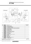
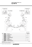
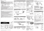
6+,0$126/;)URQW'HUDLOOHXU
)'0
&ODPS%ROW0[
6WURNH$GMXVW6FUHZV0[3ODWH
60$'6&ODPS%DQG$GDSWHUVIRU6VL]HPP
60$'0&ODPS%DQG$GDSWHUVIRU0VL]HPP
60$'6&ODPS%DQG$GDSWHUVIRU6VL]HPP
60$'0&ODPS%DQG$GDSWHUVIRU0VL]HPP
&DEOH)L[LQJ3ODWH%ROW0[
$6DPHSDUWV
%3DUWVDUHXVDEOHEXWGLIIHULQPDWHULUDOVDSSHDUDQFHILQLVKVL]HHWF
$EVHQFHRIPDUNLQGLFDWHVQRQLQWHUFKDQJHDELOLW\
0
)'
1
77
'(6&5,37,21
0
0
6+,0$12
&2'(12
<%*
<.'
<< << << << <.; )'
)'
,7(0
12
,17(5&+$1*(
$%,/,7<
%
$ $
$
$
$
6HS$
&6KLPDQR,QF:
General Safety Information
Specifications
Front Derailleur
WARNING
• Use neutral detergent to clean the chain. Do not use alkali-based or acid based detergent such as rust cleaners as it may result
in damage and/or failure of the chain.
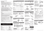
• Use the reinforced connecting pin only for connecting the narrow type of chain.
• There are two different types of reinforced connecting pins available. Be sure to check the table below before selecting which
pin to use.
Reinforced
If connecting pins other than reinforced connecting pins
Chain
Chain tool
connecting pin
are used, or if a reinforced connecting pin or tool which
is not suitable for the type of chain is used, sufficient
9-speed super narrow
Silver
connection force may not be obtained, which could
chain such as
TL-CN32 / TL-CN27
6.5mm
CN-7701 / CN-HG93
cause the chain to break or fall off.
8- / 7- / 6-speed narrow
• If it is necessary to adjust the length of the chain due
Black
chain such as
TL-CN32 / TL-CN27
to a change in the number of sprocket teeth, make the
7.1mm
CN-HG50 / CN-HG40
cut at some other place than the place where the chain
has been joined using a reinforced connecting pin or an end pin. The chain will be damaged if it
Reinforced Connecting Pin
is cut at a place where it has been joined with a reinforced connecting pin or an end pin.
• Be careful not to let the cuffs of your clothes get caught in the chain while riding, otherwise you
may fall off the bicycle.
• Check that the tension of the chain is correct and that the chain is not damaged. If the tension
End Pin
Link Pin
is too weak or the chain is damaged, the chain should be replaced. If this is not done, the chain
may break and cause serious injury.
• Use a front chainwheel which is compatible with 9-speed chains in conjunction with Shimano CN-7701,
CN-HG93 and CN-HG73 chains. If a chainwheel for an 8-speed chain or less is used, front chainwheel gear shifting problems
may occur, or the chain pins might fall out, causing the chain to break.
• The two left crank arm mounting bolts should be tightened alternately in stages rather than each bolt being fully tightened all at
once. Use a torque wrench to check that the final tightening torques are within the range of 12 - 15 N·m.
Furthermore, after riding approximately 100 km (60 miles), use a torque wrench to re-check the tightening torques.
It is also important to periodically check the tightening torques.
If the tightening torques are too weak or if the mounting bolts are not tightened alternately in stages, the left crank arm may
come off and the bicycle may fall over, and serious injury may occur as a result.
• Check that there are no cracks in the crank arms before riding the bicycle. If there are any cracks, the crank arm may break and
you may fall off the bicycle.
• If the inner cover is not installed correctly, the axle may rust and become damaged, and the bicycle may fall over and serious injury
may occur as a result.
• Obtain and read the service instructions carefully prior to installing the parts. Loose, worn or damaged parts may cause the
bicycle to fall over and serious injury may occur as a result. We strongly recommend only using genuine Shimano replacement
parts.
• Obtain and read the service instructions carefully prior to installing the parts. If adjustments are not carried out correctly, the
chain may come off and this may cause you to fall off the bicycle which could result in serious injury.
• Read these Technical Service Instructions carefully, and keep them in a safe place for later reference.
Note
• In addition, if pedaling performance does not feel normal, check this once more.
• Before riding the bicycle, check that there is no play or looseness in the connection. Also, be sure to retighten the crank arm
fixing bolt at periodic intervals. (BB-FC, FC-PD)
• If a squeaking noise is heard coming from the bottom bracket axle and the left crank arm connector, apply grease to the connector and
then tighten it to the specified torque.
• Do not wash the bottom bracket with high-pressure jets of water.
• If you feel any looseness in the bearings, the bottom bracket should be replaced.
• If gear shifting operations do not feel smooth, wash the derailleur and lubricate all moving parts.
• If the amount of looseness in the links is so great that adjustment is not possible, you should replace the derailleur.
• You should periodically wash the chainrings in a neutral detergent and then lubricate them again. In addition, cleaning the chain
with neutral detergent and lubricating it can be an effective way of extending the useful life of the chainrings and the chain.
• If the chain keeps coming off the chainrings during use, replace the chainrings and the
chain.
Front
• When the chain is in the position shown in the illustration, the chain may contact the front
chainrings
chainrings or front derailleur and generate noise. If the noise is a problem, shift the chain
onto the next-larger rear sprocket or the one after.
• Apply grease to the left and right adapters before installing them.
Rear
• For smooth operation, use the specified outer casing and the bottom bracket cable guide.
sprockets
• For details on the SIS adjustment method for double chainwheel specifications, refer to
the Service Instructions for the FD-M665/667 front derailleur.
• When installing the top route type, choose a frame that has three outer casing holders as shown in the
Outer casing holders
illustration at right.
• Use an outer casing which still has some length to spare even when the handlebars are turned all the way
to both sides. Furthermore, check that the shifting lever does not touch the bicycle frame when the
handlebars are turned all the way.
• A special grease is used for the gear shifting cable (SIS-SP41). Do not use DURA-ACE grease or other
types of grease, otherwise they may cause deterioration in gear shifting performance.
• Grease the inner cable and the inside of the outer casing before use to ensure that they slide properly.
• Operation of the levers related to gear shifting should be made only when the front chainwheel is turning.
• If the brake fluid used in the oil disc brakes is of a type which tends to adhere to the plastic parts of the shifting lever, this may
cause the plastic parts to crack or become discolored. Therefore, you should make sure that the brake fluid does not adhere to
these plastic parts.
The mineral oil which is used in SHIMANO disc brakes does not cause cracking or discoloration if it adheres to plastic parts, but
such parts should be cleaned with alcohol beforehand to prevent foreign particles from adhering.
• Do not disassemble the indicator and shifting lever unit, as this may damage them or cause mis-operation.
• Parts are not guaranteed against natural wear or deterioration resulting from normal use.
• For maximum performance we highly recommend Shimano lubricants and maintenance products
• For any questions regarding methods of installation, adjustment, maintenance or operation, please contact a professional
bicycle dealer.
X = Available
Model number
FD-M660-E FD-M660 FD-M661 FD-M665/M667 FD-M665-E
Normal type
X
X
X
X
X
Top route type
X
X
X
X
X
Front chainwheel tooth difference
22T
22T
22T
14T
14T
Min. difference between top and intermediate
12T
12T
12T
–
–
–
S, M, L
S, M, L
S, M, L
–
Front derailleur installation band diameter
Installation band diameters:
S (28.6 mm), M (31.8 mm), L (34.9 mm)
When using the S, M size, use an
installation band with a diameter of 28.6
mm, 31.8mm and install it to a L size
adapter.
Chainstay angle
66° - 69° 66° - 69° 66° - 69° 65° - 71° 65° - 71°
Chainstay angle (a)
Applicable chain line
50 mm
50 mm
50 mm
50 mm
50 mm
44T
44T / 48T
44T
36T
36T
Applicable front chainwheel
Applicable front derailleur
FC-M660
FC-M665
Double (FD-M665/M667)
36-22T
104 mm / 64 mm
104 mm / 64 mm
Crank arm length
170 mm, 175 mm
170 mm, 175 mm
50 mm
50 mm
68, 73 mm
68, 73 mm
BC1.37 (68, 73mm)
BC1.37 (68, 73mm)
Bottom bracket shell width
Thread dimensions
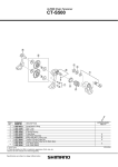
FC-M660
The level section of the chain guide outer
plate should be directly above and
parallel to the largest chainring. Secure
using a 5 mm Allen key.
Chainwheel
(largest chainring)
Chain guide
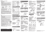
Gear shifting operation
• FD-M661
Largest sprocket
After taking up the initial slack in the cable, re-secure to the front
derailleur as shown in the illustration.
Use a handlebar grip with a
maximum outer diameter of 36 mm.
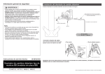
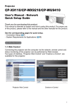
When lever (A) is pressed once, there is a shift of one step from a
small chainring to a larger chainring.
When lever (B) is pressed once, there is a shift of one step from a
large chainring to a smaller chainring.
Example:
Example:
from intermediate chainring
to largest chainring.
from largest chainring to
intermediate chainring.
If not using the indicator, this shifting lever can be installed either
on the inside or the outside of the brake lever.
If adjusting the position, remove the indicator, and then be sure
to secure it in the new position with the two fixing bolts.
Tightening torque :
2.5 N·m {22 in. lbs.}
Outboard
Lever (A) initial position
Inboard
2-way release
3
4
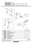
Insert the right crank unit.
5
Use the TL-FC16 to tighten the cap.
Tightening torque: 0.7 - 1.5 N·m {6 - 13 in. lbs.}
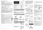
SIS Adjustment (Triple)
Set section A of the left crank into the axle of the right crank
unit where the groove is wide.
Be sure to follow the sequence described below.
1. Low adjustment
First remove the Pro-Set alignment block .
Next, set so that the clearance between the chain guide inner
plate and the chain is 0 - 0.5 mm.
■ Spacer installation method
Pro-Set alignment
block
TL-FC32
Largest
sprocket
Wide groove area
A
B
Chain guide
inner plate
5
Bracket Type
FD-M660
Smallest
chainring
1
F
A
In order to realize the best performance, we recommend that the following combination be used.
Chain
E-type
bracket
2. Connecting and securing the inner cable
6
F
A
Operate lever (B) two times or more,
and check on the indicator that the
lever is at the lowest position. Then
remove the inner hole cover and
connect the inner cable.
2
Inner cover
Lever (B)
SIS-SP41
Type
Front derailleur
Front chainwheel
FD-M660 / FD-M661 / FD-M660-E
FD-M665 / FD-M667 / FD-M665-E
FC-M660
FC-M665
CN-HG73
SM-SP17
Stopper plate
Front Chainwheel
Adapter
FC-M660
Pro-Set gauge
Gear teeth should
come within this range
Please note: specifications are subject to change for improvement without notice. (English)
© Mar. 2008 by Shimano Inc. XBC SZK Printed in Japan.
Tightening torque :
35 - 50 N·m {305 - 435 in. lbs.}
Intermediate
chainring
Chain
B
Outer edge of bash
guard should come
within this range
Inner hole cover
Pro-Set gauge
Outer end cap
Attach the same outer
end cap to the cut end of
the outer casing.
Outer casing adjustment barrel
5. Troubleshooting chart
After completion of steps 1 - 4, move the shifting lever to check the
shifting. (This also applies if shifting becomes difficult during use.)
If the chain falls to the crank
side.
Tighten the top adjustment screw
clockwise (about 1/4 turn).
If shifting is difficult from the
intermediate chainring to the
largest chainring.
Loosen the top adjustment screw
counterclockwise
(about 1/8 turn).
If shifting is difficult from the
intermediate chainring to the
smallest chainring.
Loosen the low adjustment screw
counterclockwise
(about 1/4 turn).
Loosen the top adjustment screw
If there is interference between
the chain and the front derailleur counterclockwise
(about 1/8 turn).
outer plate at the largest
chainring.
If the intermediate chainring is
skipped when shifting from the
largest chainring.
Tightening torque :
0.3 - 0.5 N·m {3 - 4 in. lbs.}
After cutting the outer casing, make the end
round so that the inside of the hole has a
uniform diameter.
Adapter
One Holland, Irvine, California 92618, U.S.A. Phone: +1-949-951-5003
Install the inner hole cover by turning it as
shown in the illustration until it stops.
Do not turn it any further than this, otherwise
it may damage the screw thread.
Cutting the outer casing
Bolt
3-77 Oimatsu-cho, Sakai-ku, Sakai-shi, Osaka 590-8577, Japan
Inner cable
Inner hole cover
Pro-Set alignment block
Front Derailleur
FC-M665
Industrieweg 24, 8071 CT Nunspeet, The Netherlands Phone: +31-341-272222
Note :
Set the stopper plate in
the right direction as
shown in illustration.
Adjust and then install the front derailleur as shown in the illustration.
Do not remove the Pro-Set alignment block at this time.
Install as shown in the illustration.
Double
Bottom bracket cable guide
This service instruction explains how to use and
maintain the Shimano bicycle parts which have
been used on your new bicycle.
For any questions regarding your bicycle or other
matters which are not related to Shimano parts,
please contact the place of purchase or the
bicycle manufacturer.
For bracket type
Triple
Chain
Push up
Chain position
A
B
Chain guide
inner plate
Tighten the top adjustment screw
If there is interference between
the chain and the front derailleur clockwise (about 1/8 turn).
inner plate at the largest
chainring.
73 mm
F
A
SLX
When carrying out adjustment, set the
chain to the largest sprocket, and at the
front, set the chain to the intermediate
chainring. Adjust using the outer casing
adjustment barrel so that the clearance
between the chain guide inner plate and
the chain is 0 - 0.5 mm.
Low adjustment
screw
(A)
2.5 mm
F
A
4. Adjustment of the intermediate
chainring
B A
3
4
F
A
F
A
Top adjustment
screw
FD-M661
A
Chain position
68 mm
Largest
chainring
Chain
Largest
sprocket
FD-M661
Spacer
Band Type
FD-M660
Set so that the clearance
between the chain guide outer
plate and the chain is 0 - 0.5
mm.
3 mm Allen key
• Install the shifting lever in a position where it will not obstruct brake
operation and gear shifting operation.
• Do not use in a combination which causes brake operation to be
obstructed.
Push in the stopper plate and check that the plate pin is
securely in place, and then tighten the bolt of the left crank
arm.
Note : Each of the bolts should be evenly and equally
tightened to 12 - 15 N·m {106 - 132 in. lbs.}.
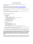
(1) Check whether the width of the bottom bracket shell is
68 mm or 73 mm.
(2) Next, install the adapter while referring to the
illustrations below.
3. Top adjustment
Chain guide
outer plate
3 mm Allen key
Follow the procedure in the figure.
6
Pull
Pull
Smallest
sprocket
Installation of the Front Chainwheel and Front Derailleur
(counterclockwise thread) and the left adapter (clockwise
thread).
Tightening torque: 35 - 50 N·m {305 - 435 in. lbs.}
Top route type
Chain position
Lever (B)
1, 2 Use the special tool TL-FC32 to install the right adapter
Normal type
Tightening torque :
5 N·m {44 in. lbs.}
Plate pin
Outer casing
Wire
fixing bolt
Largest chainring
Tightening torque :
5 - 7 N·m {44 - 60 in. lbs.}
4 mm Allen key
To shift from a large chainring to a smaller chainring
F
A
SL-M660
< Top route type >
< Normal type >
Installation of the lever
To shift from a small chainring to a larger chainring
73 mm
Rapidfire (Shifting lever)
5 mm Allen key
Note:
Pass the cable
through as shown
in the illustration.
Add 2 links (with the chain on both
the largest sprocket and the largest
chainring)
This release lever is equipped with a 2-way release mechanism which allows release operations to be carried out by either pushing or pulling
the lever.
Both lever (A) and lever (B) always return to the initial position when they are released after shifting.
When operating one of the levers, always be sure to turn the crank arm at the same time.
TL-FC16
Series
Wire
fixing bolt
Tightening torque :
5 - 7 N·m {44 - 60 in. lbs.}
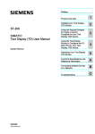
SI-6PZFA-002
Front Drive System
Note:
Pass the cable
through as shown
in the illustration.
Chain
68 mm
Technical Service Instructions
< Top route type >
Chain length
44-32-22T / 48-36-26T
Bolt circle diameter
Chain line
< Normal type >
The inner surface of the bash guard
should be at the flat part of the chain
guide outer plate.
Triple (FD-M660-E/M600/M661)
Chainwheel tooth combination
• FD-M660
When installing the components to carbon frame/handle bar
surfaces, verify with the manufacturer of the carbon frame/parts for
their recommendation on tightening torque in order to prevent over
tightening that can cause damage to the carbon material and/or
under tightening that can cause lack of fixing strength for the
components.
FC-M665
Chainwheel
Model number
■ Note
Loosen the outer casing
adjustment barrel
counterclockwise (1 or 2 turns).
If there is interference between
Tighten the outer casing
the chain and front derailleur
adjustment barrel clockwise
inner plate when the rear
(1 or 2 turns).
sprocket is shifted to the largest
sprocket when the chainwheel is
at the intermediate chainring
position.
If the chain falls to the bottom
bracket side.
Tighten the low adjustment screw
clockwise (about 1/2 turn).
If the lever is stiff when shifting
from the intermediate chainring
to the largest chainring
Loosen the top adjustment screw
counterclockwise (about 1/4
turn).
■ Refer to the Service Instructions for the Rear Drive
System for details on replacing and installing the
indicator unit.