1
Universidade do Minho
Escola de Engenharia
Nuno Miguel Eira de Sousa
WildAniMAL
MAL Interactors Model Animator
Novembro de 2012
Universidade do Minho
Escola de Engenharia
Departamento de Informática
Nuno Miguel Eira de Sousa
WildAniMAL
MAL Interactors Model Animator
Dissertação de Mestrado
Mestrado em Engenharia Informática
Trabalho realizado sob orientação de
Professor José Creissac Campos
Novembro de 2012
Acknowledgements
I want to thank my thesis advisor José Creissac Campos for continuously helping me while
doing this work, by making many corrections and valuable suggestions for the implementation of
the WildAniMAL and for pointing errors and problems during the design and implementation of
the tool.
I also want to thank Manuel Sousa for providing me with a practical example of an Ipod
device model, that enabled me to show how the WildAniMAL plugin can be used. Additionally I
thank him for testing the WildAniMAL plugin, with interactor models that he developed in his own
work.
Finally, I want to thank my employer - Computer Graphics Center – for giving me a day a
week for education, during the last three years, thus enabling me to conclude this master’s
course with the current work.
i
Abstract
The IVY Workbench is a tool for modeling and analysis of interactive systems which has been
developed at the Department of Informatics of the University of Minho (http://ivy.di.uminho.pt).
It's a platform developed in Java, using a plugins mechanism. The available plugins include a set
of editors (textual and graphical) and tools to analyse the behaviour of the models. The
experience on using the tool has demonstrated the need for a model animator which could
enable a first interactive evaluation of the models. Therefore this dissertation describes the
design and implementation of WildAniMAL - a MAL (Modal Action Logic) interactors models
animator – as a plugin for the IVY Workbench. The plugin uses the NuSMV model checker
simulations capabilities, and enables users to explore the formal models interactively.
ii
Resumo
A IVY Workbench é uma ferramenta de modelação e análise de sistemas interativos que tem
vindo a ser desenvolvida no Departamento de Informática da Universidade do Minho
(http://ivy.di.uminho.pt). Trata-se de uma plataforma desenvolvida maioritariamente em Java,
utilizando um mecanismo de plugins. Os plugins existentes incluem um conjunto de editores (em
modo texto e gráfico), e de ferramentas de análise do comportamento dos modelos. A
experiência de utilização da ferramenta tem, no entanto, demonstrado a necessidade de um
animador de modelos que permita efetuar uma primeira validação interativa dos mesmos. Sendo
assim, esta dissertação descreve o desenho e implementação do WildAniMAL – um animador de
modelos de MAL (Modal Action-Logic) Interactors – como plugin para a IVY Workbench. O plugin
usa as capacidades de simulação do model checker NuSMV, e permite aos utilizadores explorar
os modelos formais de forma interativa.
iii
Index
Acknowledgements _____________________________________________________ i Abstract _____________________________________________________________ ii Resumo ______________________________________________________________ iii Index ________________________________________________________________ iv Figures ______________________________________________________________ vii Acronyms ____________________________________________________________ ix Chapter 1 – Introduction ________________________________________________ 1 1.1. Goal __________________________________________________________________ 2 1.2. Structure Of The Document _______________________________________________ 2 Chapter 2 – Theoretical Background _______________________________________ 3 2.1. Model Checking _________________________________________________________ 3 2.2. NUSMV _______________________________________________________________ 5 2.3. Finite State Machine _____________________________________________________ 7 2.4. Binary Decision Diagrams _________________________________________________ 9 2.5. MAL Interactors ________________________________________________________ 11 2.6. SMV Language _________________________________________________________ 12 2.7. CTL __________________________________________________________________ 13 2.8. Conclusion ____________________________________________________________ 14 Chapter 3 – IVY Workbench _____________________________________________ 16 3.1. The IVY Workbench Approach ____________________________________________ 16 3.1.1 Creating Models ____________________________________________________________ 17 iv
3.1.2 Expressing Properties ________________________________________________________ 19 3.1.3 Verification ________________________________________________________________ 20 3.1.4 Trace Analysis ______________________________________________________________ 21 3.2. How To Create An IVY Workbench Plugin ___________________________________ 25 3.3. Conclusion ____________________________________________________________ 28 Chapter 4 – Related Work ______________________________________________ 29 4.1. CTTE _________________________________________________________________ 29 4.2. AniMAL _______________________________________________________________ 32 4.3. Conclusion ____________________________________________________________ 34 Chapter 5 – WildAniMAL Implementation Approaches _______________________ 35 5.1. Implementation Approaches _____________________________________________ 35 5.1.1 Generating a Finite State Machine _____________________________________________ 36 5.1.2 NuSMV Binary Decision Diagrams ______________________________________________ 37 5.1.3 NuSMV Simulation Capabilities ________________________________________________ 37 5.2. NuSMV Interactive Shell _________________________________________________ 39 5.2.1 Model Reading And Building __________________________________________________ 39 5.2.2 Simulation Commands _______________________________________________________ 40 5.2.3 Simulation Example _________________________________________________________ 41 5.3. Conclusion ____________________________________________________________ 46 Chapter 6 – WildAniMAL Implementation _________________________________ 47 6.1. WildAniMAL’s Architecture ______________________________________________ 47 6.2. WildAniMAL’s Source Code Description ____________________________________ 53 6.2.1 Animator Package __________________________________________________________ 53 6.2.2 Constraints Package _________________________________________________________ 62 6.2.3 NuSMV Package ____________________________________________________________ 64 6.3. Conclusion ____________________________________________________________ 68 Chapter 7 – Using WildAniMAL __________________________________________ 70 7.1. WildAniMAL’s Usage Example __________________________________________________ 70 7.2. Conclusion _________________________________________________________________ 80 Chapter 8 – Conclusions and Future Work _________________________________ 81 v
8.1. Goal _________________________________________________________________ 81 8.2. Results _______________________________________________________________ 81 8.3. Future Work ___________________________________________________________ 83 References __________________________________________________________ 84 Appendix I – Build.xml _________________________________________________ 87 Appendix II – Ipod interactors model _____________________________________ 93 vi
Fig
gures
FIGUREE 1 MODEL CHECCKING SYSTEM, AADAPTED FROM [[9], WITH THE IV
VY WORKBENCH APPROACH. ................................... 4 FIGUREE 2 A GRAPH OF AN EXTREMELY BBASIC PROCESS INN A FINITE STATEE MACHINE. .......................................................... 8 FIGUREE 3 FSM EXAMPPLE OF A PARSER RECOGNIZING TTHE WORLD "NICE". ..................................................................... 9 FIGUREE 4 DIAGRAM FO
OR , TAKEN FROM [116]. ......................................................................................... 9 FIGUREE 5 ROBDD FORR (X1⇔Y1)^(X2⇔
2 Y2) WITH VAARIABLE ORDERIN
NG X1<X2<Y1<Y2, TAKEN FROM
M [17]. .................. 10 FIGUREE 6 IVY WORKBENCH ARCHITECTTURE. ........................................................................................................... 17 FIGUREE 7 MODEL EDITTOR PLUGIN (GRAAPHICAL). ..................................................................................................... 18 FIGUREE 8 MODEL EDITTOR PLUGIN (TEXXT). .............................................................................................................. 18 FIGUREE 9 PROPERTIES EDITOR. ............................................................................................................................. 19 FIGUREE 10 BEHAVIOURR TRACE. ............................................................................................................................. 21 FIGUREE 11 TRACE ANAALYSIS MECHANISSMS (MARKERS).. ........................................................................................... 21 FIGUREE 12 TREE VISUAAL REPRESENTATION. ............................................................................................................. 22 FIGUREE 13 STATE BASEED VISUAL REPREESENTATION. .................................................................................................. 23 FIGUREE 14 LOGICAL STATES VISUAL RE
T
PRESENTATION. .............................................................................................. 23 FIGUREE 15 TABULAR VVISUAL REPRESENTATION. ....................................................................................................... 24 FIGUREE 16 ACTIVITY DIAGRAM VISUAL REPRESENTATIOON. ........................................................................................ 24 FIGUREE 17 IVY WORKBENCH PLUGINS FRAMEWORK. .............................................................................................. 25 FIGUREE 18 CTTE TOOLL, TAKEN FROM [25]. ..............
[
............................................................................................. 30 FIGUREE 19 AN EXAMPLLE OF A TASK MO
ODEL, TAKEN FRO
OM [25]. ................................................................................ 30 FIGUREE 20 OVERVIEW OF THE CTT NOTATION, TAKEN FFROM [28]. ............................................................................ 31 FIGUREE 21 A SIMPLE CONCURTASKTREEE TASK MODEL SSIMULATOR, TAKKEN FROM [28]. .................................................. 32 FIGUREE 22 THERMOMETER, TAKEN FRO
OM [29]. ...................................................................................................... 33 FIGUREE 23 PROTOTYPEE OF AN AIR CONDITION CONTRO L PANEL, TAKEN FROM [29]. ...................................................... 34 FIGUREE 24 NUSMV SIMULATION EXAM
MPLE. ........................................................................................................... 38 FIGUREE 25 INTERACTO
ORS MODEL OF A GARAGE GATE. ............................................................................................... 42 FIGUREE 26 STATE DIAG
GRAM OF GATE M
MODEL. ......................................................................................................... 42 FIGUREE 27 NUSMV SPPECIFICATION OFF THE GATE MOD EL. ........................................................................................ 43 FIGUREE 28 THE RESULTT OF PICK_STATEE –I –A COMMANND. ........................................................................................ 44 FIGUREE 29 THE RESULTT OF SIMULATE –I –A –K 1 COMM
MAND. ................................................................................... 44 vii
FIGURE 30 THE RESULT OF CHOOSING STATE 0. ..................................................................................................... 45 FIGURE 31 STATE BASED DIAGRAM SHOWING THE SIMULATION PATH. ....................................................................... 45 FIGURE 32 WILDANIMAL PLUGIN ARCHITECTURE AS A PACKAGE DIAGRAM. ............................................................... 48 FIGURE 33 MAIN PACKAGE CLASS DIAGRAM. ........................................................................................................ 49 FIGURE 34 NUSMV PACKAGE CLASS DIAGRAM. .................................................................................................... 50 FIGURE 35 CONSTRAINTS PACKAGE CLASS DIAGRAM. .............................................................................................. 51 FIGURE 36 TRACES PACKAGE CLASS DIAGRAM. ...................................................................................................... 52 FIGURE 37 GRAPHICAL USER INTERFACE IMPLEMENTED BY GUI CLASS. ...................................................................... 55 FIGURE 38 IPOD MODEL CREATION WITH MODEL EDITOR PLUGIN. ............................................................................ 71 FIGURE 39 IPOD INTERACTOR MODEL COMPILATION WITH PROPERTIES EDITOR PLUGIN. ................................................ 72 FIGURE 40 RESULT OF PRESSING “GET INITIAL STATE” IN WILDANIMAL. .................................................................. 73 FIGURE 41 SIMULATION REACHED A “TOO MANY STATES” SITUATION. ...................................................................... 74 FIGURE 42 STATE BASED REPRESENTATION OF THE TRACE CREATED IN THE SIMULATION. ............................................... 75 FIGURE 43 TABULAR REPRESENTATION OF THE TRACE CREATED IN THE SIMULATION. ..................................................... 75 FIGURE 44 LOG REPRESENTATION OF THE SIMULATION. .......................................................................................... 76 FIGURE 45 CONSTRAINTS INSERTION. .................................................................................................................. 77 FIGURE 46 RESULT OF APPLICATION OF THE CONSTRAINTS SENT. ............................................................................... 77 FIGURE 47 STATE BASED REPRESENTATION OF A TRACE ORIGINATED IN A SIMULATION. ................................................. 79 viii
Acronyms
BDD
Binary Decision Diagrams
CMU
Carnegie Mellon University
CTEE
ConcurTaskTrees Environment
CTL
Computacional Tree Logic
CTT
ConcurTaskTrees
CUDD
CU Decision Diagram Package
ETC
Enabled Task Collection
FSM
Finite State Machine
IRST
Istituto per la Ricerca Scientica e Tecnologica
IVY
Interactors VerifYier
LTL
Linear Temporal Logic
MAL
Modal-Action Logic
RBC
Reduced Boolean Circuit
SAT
Satisfiability Problem
SMV
Symbolic Model Verifier
UI
User Interface
UML
Unified Modeling Language ix
Chapter 1 – Introduction
Developing complex systems will always be a complex endeavour. When developing
interactive devices, we are faced with the challenge of understanding not only how the device
must be built, but also how it will interact with its users, and how both device and users (the
interactive system) will influence each other.
Formal (mathematically rigorous) methods have long been proposed as a means of dealing
with complexity. When considering the behaviour of systems, model checking [1] has gained
particular popularity. Several approaches to the application of model checking to reason about
interactive systems (or interactive devices) have been put forward over the last seventeen years.
See, for example, the work in [2], [3], or [4]. However, applying model checking is in itself a
complex task. Both systems and Properties to be verified must be expressed in appropriate
logics. In order to make model checking of interactive systems feasible, we must provide tools
that help in the modelling and analysis process.
The IVY Workbench tool supports the modelling and verification approach put forward in [3].
The main goal of the tool is the detection of potential usability problems early in development of
any interactive system. For that, the tool enables the automated inspection of interactive systems
models. The tool supports a modelling and analysis cycle where the models are obtained by a
modelling process based on an editor, the properties are expressed using a dedicated properties
editor, the analysis is performed using the SMV model checker [5] (more specifically NuSMV [6],
a reimplementation of that tool, that is available at http://nusmv.fbk.eu), and the counterexamples visualized using a dedicated traces visualiser. The tool has been applied to the analysis
of different devices, from control panels in the automotive industry [7], to medical devices such
as infusion pumps [8]. While model checking through NuSMV, enables a thorough analysis of all
possible behaviours of a model, the continuous use of the tool has highlighted the need for a
1
lighter weight approach to the initial validation of the models. In fact, experience has shown that
before the analysis of a given design begins, there usually happens a first phase of model
validation, where the interest is in establishing that the model behaves as expected. Experience
also shows that doing this through model checking becomes cumbersome. What is needed is the
possibility of interactively explore the behaviour of the models: manually trigger events and
observe how the system evolves. Hence the need was identified of developing a component
aiming at assisting the modelling and analysis process, by providing functionalities to simulate
and validate the model being created: WildAniMAL (Watch It vaLiDation Animator for MAL).
1.1. Goal
The goal of this work is to develop a new plugin – WildAniMAL – for the IVY Workbench tool,
supporting the animation of MAL interactor models. In order to implement it, three possibilities
will be studied:
a) representing a MAL interactors model as a Finite State Machine (FSM) and use that to
drive the animation;
b) use the BDD (Binary Decision Diagrams) representation of the MAL interactors model,
created by the NuSMV model checker to perform the animation;
c) use the NuSMV model checker simulations commands, available on its interactive mode,
to perform the animation.
1.2. Structure Of The Document
This first chapter has presented the motivation and goals of the work. The remaining of the
dissertation is structured as follows. Chapter 2 introduces the main concepts needed to
understand the work. Chapter 3 introduces the IVY workbench tool. Chapter 4 describes some
related tools. Chapter 5 discusses alternatives to implementing the WildAniMAL plugin, and
chapter 6 the implementation produced. Chapter 7 describes an usage example. The dissertation
ends, in Chapter 8, with a discussion of results and ideas for further work.
2
Chapter 2 – Theoretical
Background
This chapter presents the theoretical background needed to explain the WildAniMAL
implementation and all the concepts related to its use, and the use of the IVY Workbench, in
which it will be integrated.
Section 2.1 presents Model Checking the technology used by the IVY Workbench to perform
verification. Section 2.2 presents NuSMV that is the model checker used in IVY Workbench, and
therefore also used to implement WildAniMAL’s functionalities. Section 2.3 presents Finite State
Machines, a mathematical model of computation, and also a state’s representation, widely used
to describe computer programs. Section 2.4 presents Binary Decision Diagrams, the data
structure used to represent a Boolean function. Two representations used in NuSMV as internal
representations. Section 2.5 presents the MAL interactors language used to create models that
will be simulate in the WildAniMAL plugin, and Section 2.6 presents the SMV language, the
language into which MAL interactors models are compiled for verification and (now) animation.
Finally, CTL is presented, that is a temporal logic that is used to express properties over the
interactors model. These properties can be verified using NuSMV model checker.
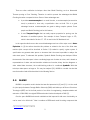
2.1. Model Checking
Clarke [9] formally describes the Model Checking problem as:
Let M be a Kripke structure (i.e., state-transition graph). Let f be a formula of
temporal logic (i.e., the specification). Find all states s of M such that M; s |= f.
3
TThat is, givenn a state-transition graph and a speciffication, we want
w to find aall states in M that
satisffy the specificcation.
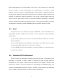
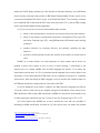
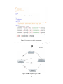
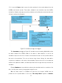
TThe structuree of a typical Model Cheecking system
m, as Clarke defined it [99], is describbed in
Figuree 1. There thhe two mainss componentss of a model checking system are preesented:
A pre
eprocessorr that extractss a state trannsition graph from a proggram or circuit;
A mo
odel check
ker, that is, an engine thhat takes thee state transsition graph and a
tempporal formulaa and determ
mines whetheer the formula is true or nnot (in the case of
the IVVY Workbencch this is NuSSMV).
Figure 1 Moodel checkingg system, adaapted from [9
9], with the IVY Workbencch approach.
FFigure 1 incluudes IVY Workbench’s pl ugins and seervices that help
h in the seeveral steps of the
modeel checking process. Thhe IVY Work bench approoach to Moddel Checkingg is presentted in
Sectioon 3.1.
4
There are other verification techniques other than Model Checking, such as Automated
Theorem proving or Proof Checking. Therefore is useful to present the advantages that Model
Checking has when compared to them. Some of these advantages are:
It provides counterexamples. In a model checker, a counterexample (an execution
trace) is produced to show why a specification does not hold. This is a great
advantage because counterexamples are great to debug complex systems. Some
people use Model Checking just for this feature;
It uses Temporal Logics that can easily express properties for proving over the
behaviour of modelled systems. One example of these Temporal Logics is CTL,
which is described in Section 2.7. CTL is used in the IVY Workbench tool.
In the opposite side there are also some disadvantages and one of the major ones is State
Explosion. In [3] the authors describe this problem as related to the size of the finite state
machine (this concept will be described in Section 2.3) needed to specify a given system. A
specification can generate state spaces so immense that it becomes impossible to analyse the
entire state space. To attenuate this problem, Symbolic Model Checking was developed. When
the traversal of the state space is done considering large sets of states at a time, and is based on
representations of states sets and transition relations as formulas, binary decision diagrams or
other related data structures, the model-checking method is considered Symbolic. With that
technique state spaces as large as 1020 may be analysed [10]. NuSMV is a model checker that
uses that method and will be described in the following Section.
2.2. NUSMV
NUSMV is a symbolic model checker that was first presented in [6] and [11]. It is the result
of a joint project between Carnegie Mellon University (CMU) and Istituto per la Ricerca Scientica e
Tecnologica (IRST) and is the final product of an effort of reengineering, reimplementation and
extension of CMU SMV, the original BDD-based model checker developed at CMU [5].
Over the years NuSMV had several contributions that improved it with more functionality, as
can be seen in its official site1. Now it combines a BDD-based model checking component that
1
http://nusmv.fbk.eu/ Last visited in 10-28-2012.
5
exploits the CUDD2 library developed by Fabio Somenzi at Colorado University, and a SAT-based
model checking component that includes an RBC-based Bounded Model Checker, which can be
connected to the Minisat SAT Solver3 and/or to the ZChaff SAT Solver4. The University of Genova
has contributed SIM, a state-of-the-art SAT solver used until version 2.5.0, and the RBC package
used in the Bounded Model Checking algorithms.
In [12] we can see the current main functionalities that it provides:
allows for the representation of synchronous and asynchronous finite state systems;
allows for the analysis of specifications expressed in Computational Tree Logic (CTL)
and Linear Temporal Logic (LTL), using BDD-based and SAT-based model checking
techniques.
provides Heuristics for achieving efficiency and partially controlling the state
explosion;
provides a textual (interactive mode) and a batch mode interface to interact with its
users.
NuSMV, as a model checker, can verify properties of a finite system and for that to be
possible a model of the system (in fact, in terms of model checking, a specification of the
system) has to be created. NuSMV uses the SMV Language (see Section 2.7) to define the
specifications used as input. In [13] it is described how this language can be used to allow for the
description of Finite State Machines (FSM) which can be completely synchronous or completely
asynchronous. More specifically the SMV Language is used to describe the transition relation of
the FSM that describes the valid evolutions of the state of the FSM.
In the IVY Workbench, that model is created in the MAL Interactors language (see Section
2.5), that is easier to learn and can be compiled (using the IVY Workbench i2smv service) into a
SMV specification. After having a SMV specification, NuSMV can verify that a model satisfies a set
of desired properties specified by the user. For that, it uses two Temporal Logics: CTL or LTL.
One useful feature that NuSMV has is that it provides the user with the possibility of
simulating a NuSMV specification. As stated in [13], this way the user can explore the possible
2
http://vlsi.colorado.edu/~fabio/CUDD/ Last visited in 10-28-2012.
3
http://minisat.se/ Last visited in 10-28-2012.
4
http://www.princeton.edu/~chaff/zchaff.html Last visited in 10-28-2012.
6
executions (traces) of the NUSMV specification. In this way, the user can check the specification
correctness, before actually engaging in the verification of properties. An example of the use of
this feature can be seen in Section 5.2.3.
2.3. Finite State Machine
When modelling the behaviour of systems, State Machines are one of the oldest and best
ways known. They define the state of a system at a particular point in time and characterize its
behaviour based on that state.
If we want to model and design software systems we can apply the State Machines method
by identifying the states the system can be in, which inputs or events trigger state transitions, and
what system behaviour is expected in each state. The execution of the software can be seen as a
sequence of transitions that move the system through its various states.
The characteristics of a system that enable it to be modelled as a Finite State Machine (FSM)
are [14]:
The system must be specifiable as a finite set of states;
The system must have a finite set of inputs and/or events that can trigger
transitions between states;
The behaviour of the system at a given point in time depends upon the current state
and the input or event that occur at that time only;
For each state the system may be in, behaviour is defined for each possible input
or event;
The system has a particular initial state.
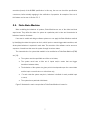
Figure 2 illustrates the main concepts that a Finite State Machine is known for.
7
Figurre 2 A graph of an extrem
mely basic proocess in a fin
nite state macchine.
TThe concepttual definitioon of the F SM can be expressed more formaally (in this case
mathematically) [15] as a quinntuple
, where:
is the input alpphabet (a finiite, non-emptty set of symbols).
is a finite, non--empty set off states.
iss an initial staate, an elemeent of .
is the state-transition functtion:
(for a nonddeterministicc finite
autom
maton it becoomes
, i.e.,
returns a set of statess).
iss the set of final states, a (possibly em
mpty) subset of .
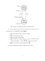
AAn example of
o the graphiccal representtation of a FSSM is presented in Figuree 3.
8
F
Figure
3 FSM
M example off a parser reccognizing thee world "nice ".
2.4
4. Binaryy Decisio
on Diagrrams
B
Binary Decision Diagrams (BDD) [166] can be deefined as a data structu re that is ussed to
repreesent a Booleean function (see Figure 4 for an exxample). We can also sayy it a comprressed
repreesentation of sets or relations.
AAndersen [177] provides a formal deffinition of a BDD. He deefines it as a rooted, directed
acyclic graph withh:
one or two terminal nodes off out-degree zero
z labeled 0 or 1, and
a seet of variablee nodes u of out-degree two. The twoo outgoing eedges are givven by
two functions lo
ow(u) and high(u). A variable va
ar(u) is assoociated with each
variaable node.
Figuree 4 Diagram for
, taken from
m [16].
9
W
When mentiooning BDDs it is importtant to menttion if they are
a ordered or not. Anddersen
definees a BDD as Ordered (OB
BDD) if on alll paths throuugh the graph the variablles respect a given
linearr order x1 < x2
x < … < xn.
AAn (O)BDD is
i Reduced (R(O)BDD) ((see Figure 5)
5 if
(uniqqueness) no two distinct nodes u andd v have the same variabble name and lowand high-successsor, i.e.,
var(u) = var((v); low(u) = llow(v); high(uu) = high(v) implies u = vv;
and
(nonn-redundant tests)
t
no variiable node u has identicaal low- and hhigh-successoor, i.e.
low(uu) ≠ high(u).
Figgure 5 ROBD
DD for (x1⇔y1
1)^(x2⇔y2) w
with variable ordering x1<
<x2<y1<y2, taaken from [1
17].
10
In most cases, when BDDs are referred to, it is implied that we are referring to Reduced
Ordered Binary Decision Diagrams.
Bryant [18] studied the BDD potential for being used to create efficient algorithms. He
introduced a fixed variable ordering (for canonical representation) and shared sub-graphs (for
compression). After that he extended the sharing concept to several BDDs, i.e. one sub-graph by
several BDDs and, doing that, he defined the data structure Shared Reduced Ordered Binary
Decision Diagram. That new structure is normally what people have in mind when mentioning
BDDs.
The NuSMV model checker uses BDDs, because they are very efficient and can be used to
create efficient algorithms, as shown in [18]. The efficiency of algorithms is important in the area
of Model Checking, and because of that the use of BDDs by NuSMV was an obvious choice.
2.5. MAL Interactors
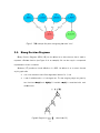
MAL interactors follow from the notion of interactor put forward in [19]: an object with the
capability of rendering part of its state to some presentation medium. A MAL interactor is defined
by:
a set of typed attributes that define the interactor's state;
a set of actions that define operations on the set of attributes;
a set of axioms written in MAL [20] that define the semantics of the actions in terms of
their effect on interactor's state.
The mapping of the interactor's state to the presentation medium is accomplished by
decorating the attributes with modality annotations. MAL axioms define how the interactor's state
changes in response to actions being executed on the interactor. In [3] the axioms are defined in
five types. In the syntax of each type, the notation prop(expr1,..,exprn) is used to denote a formula
on expressions expr1 to exprn using propositional operators only. Also, the names a1 to an
denote interactor attributes and ac denotes an action. The five types are:
Invariants – these are formulae that do not involve any kind of action or (reference)
event (i.e. simple propositional formulae). They must hold for all states of the interactor;
o Syntax: prop(a1,..,an).
11
Initialisation axioms – these are formulae that involve the reference event ([]). They
define the initial state of the interactor;
o Syntax: [] prop(a1,..,an).
Modal axioms – these are formulae involving the modal operator. They define the
effect of actions in the state of the interactor;
o Syntax: prop([ac] a1,..,[ac]ag, ah,..,an).
Permission axioms – these are deontic formulae involving the use of per. They
define specific conditions for actions to be permitted to happen;
o Syntax: per(ac) → prop(a1,..,an)
Obligation axioms – these are deontic formulae involving the use of obl. They define
the conditions under which actions become obligatory.
o Syntax: prop(a1,..,an) → obl(ac)
2.6. SMV Language
The SMV language will be used as an intermediate representation of the MAL interactors
model. Therefore an explanation of the main aspects of the SMV language is needed. The
following description of the language is adapted from [3] and [12].
An SMV specification is defined as a collection of modules. Each module defines a Finite
State Machine (FSM) and consists of a number of state variables, input variables and frozen
variables, a set of rules that define how the module makes a transition from one state to the next
and Fairness conditions that describe constraints on the valid paths of the execution of the FSM.
A state model is defined as an assignment of values to a set of state and frozen variables.
State variables can change their values throughout the evolution of the FSM. Frozen variables
cannot, as they retain their initial value, and that is what distinguishes the two. Input variables
are used to label transitions of the Finite State Machine.
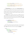
An example of an SMV specification is the following:
MODULE main
-- attributes
VAR
currentSong: 0..5;
12
lastDisplay: {MainMenu, Music, Playing, OFF};
playbackState: {playing, paused, stoped};
display: {MainMenu, Music, Playing, OFF};
-- actions
VAR
action: {pause, longPlay, play, nil};
-- axioms
INIT display = OFF
INIT playbackState = stoped
INIT lastDisplay = MainMenu
INIT currentSong = 0
TRANS next(action)=pause -> playbackState = playing
TRANS next(action)=play -> playbackState = stoped | playbackState =
paused
INIT action = nil
To create a SMV specification the following list of declarations is used:
VAR allows the declaration of state variables;
IVAR allows the declaration of input variables;
FROZENVAR allows the declaration of frozen variables;
INIT allows the definition of the initial states of the model;
INVAR allows the specification of invariants over the state.
TRANS allows the definition of the behaviour of the model. In these definitions,
the operator next is used to refer to the next state;
FAIRNESS allows the declaration of fairness constraints, that is, conditions that
must hold infinitely often over the execution paths of the model.
2.7. CTL
When reasoning about the behaviour of a system is needed, CTL can be used to express the
properties for that purpose. The detailed description of CTL and its formal description are
available in [21]. A more compact description of its operators is given here. As other similar
languages CTL provides propositional logic connectives but it also allows for operators over the
computation paths that can be reached from a state.
13
A - for all paths (universal quantifier over paths);
E - for some path (existential quantifier over paths).
and over states in a computation state:
G - used to specify that a property holds at all the states in the path (universal quantifier
over states in a path);
F - used to specify that a property holds at some state in the path (existential quantifier
over states in a path);
X - used to specify that a property holds at the next state in the path;
U - used to specify that a property holds at all states in the path prior to a state where a
second property holds.
These operators provide for an expressive language because combining them it is possible to
express important concepts such us:
universally: AG(p) - p is universal (for all paths, in all states, p holds);
inevitability: AF(p) - p is inevitable (for all paths, for some state along the path, p
holds);
possibility: EF(p) - p is possible (for some path, for some state along that path, p
holds).
2.8. Conclusion
This chapter presented all the theoretical background needed to explain the WildAniMAL
implementation and the tool in which it is integrated – the IVY Workbench.
Section 2.1 presented Model Checking that is the area in which this work is framed, and
Section 2.2 presented NuSMV that is the model checker used widely in IVY Workbench, and
which will also be used in the WildAniMAL plugin.
Sections 2.3 and 2.4 presented Finite State Machine and Binary Decision Diagrams, two
representations studied as possible approaches for WildAniMAL’s internal data structure. BDD is
used also in NuSMV as one of its data structures.
Section 2.5 presented the MAL interactors language used to create interactor models, and
Section 2.6 presented the SMV language that will be used as an intermediate representation of
the first one, because it is the language NuSMV uses.
14
Finally, CTL was presented. This language is used to express properties over the interactor
models, created with the MAL interactors language, and compiled to a NuSMV specification.
15
Chapter 3 – IVY Workbench
This chapter presents the IVY Workbench tool that supports the modelling and analysis of
interactive systems. It is a plugins platform (developed in Java) that includes a set of editors and
tools to analyse the models’ behaviour.
Section 3.1 presents the IVY Workbench approach, relating to model checking, that consists
on creating a MAL model, expressing properties over it, making a verification with the help of the
NuSMV model checker and analysing its results.
Section 3.2 describes how to create a new plugin for the IVY Workbench, as this is useful to
know how to implement the proposed WildAniMAL plugin.
3.1. The IVY Workbench Approach
In [3] and [4] an approach to the application of model checking to the analysis of interactive
systems is put forward. The approach is based in the development of models of the interactive
device, and in their verification trough model checking against properties that encode
assumptions about the usages of the device.
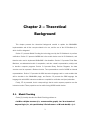
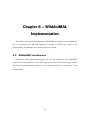
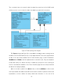
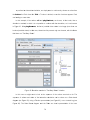
Figure 6 shows the architecture of the tool, added with the proposed WildAniMAL plugin. As
it can be seen, the tool consists on a number of plugins, and uses NuSMV as the verification
engine. In this section the different plugins are described (except WildAniMAL, which will be
discussed later, see Chapter 7).
16
Figure 6 IVYY Workbench architecture.
3.1..1 Creatiing Models
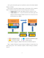
A MAL modeel is construccted compossing interactoors in a hierrarchical form
m. The process of
MAL model creattion is suppoorted by thee Model Edittor plugin of the tool. Thhe plugin haas two
modees: Graphical (see Figure 7) that uses a notation similar
s
to UML class diagrrams (described in
[22]) and Text (seee Figure 8) that
t providess code completion facilitiees.
17
Figure 7 Modeel Editor pluggin (Graphicaal).
Figure 8 Moodel Editor plugin
p
(Text).
18
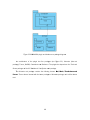
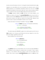
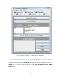
3.1..2 Expressing Pro
operties
TThe propertiees for verificcation are w
written in CTL [1]. Propeerties are wrritten that exxpress
assum
mptions abouut the expectted behaviou r of the devicce.
TThe process of expressing properties is supportedd by the Prop
perties Editoor plugin of thhe IVY
Workbench tool (see Figure 9). The pluugin is basedd on sets of patterns thhat capture usual
propeerties typically verified of any interactivve system. The
T patterns used by the IIVY workbencch are
descrribed in [23]. Each pattern describes its intent, provides a praactical exam ple and has some
param
meters. Afterr choosing thhe most suiteed pattern foor the propertty he or she wants to express,
the user of the toool has only too define the values of thee parameterss of the patteern. For doingg that,
the toool has an assisted mode, in which tthe user seleects attributees and actionns from the model
for the parameterrs of the patteern.
Figure 9 Propertiess Editor.
19
3.1.3 Verification
The verification step is performed by the NuSMV model checker. To make the verification
possible, MAL interactor models are compiled to the SMV language. A detailed description of the
verification approach is out of the scope of this dissertation. For the discussion that follows what
is important is that, when a given property is not verified, NuSMV tries to provide a behaviour of
the model (a trace) that demonstrates the falseness of the property in question. These traces
(see Figure 10 for an extract) consist of a sequence of states of the model that violates the
property under scrutiny.
Because of limitations on the SMV input language, when compared to MAL interactors, the
compilation step mentioned above introduces a series of auxiliary variables in the model. This
means that the trace is not at the same level of abstraction as the interactor model being verified.
One aspect were this is particularly evident is the treatment of actions. Because SMV models do
not have an explicit notion of action, the compilation process introduces a special attribute action - used for modelling, in each state, which action has just occurred.
Another aspect that deserves mention is a mismatch in the execution models of both
languages. At MAL interactors level, the actions of different interactors can happen in an
asynchronous way. Thus, an interactor can execute one action while the others remain inactive.
At the SMV level, however, the transitions occur in a synchronous way. This means that when a
module performs a transition all modules in the model must also perform a transition. To model
asynchronous state transitions, it becomes necessary to introduce a special action nil that at the
MAL interactors level (what we will call the logical level from now on) corresponds to nothing
happening, while at SMV level (what we will call physical level from now on) represents a state
transition (to a state with the same attributes values i.e. to the same logical state). This way, the
SMV module corresponding to an interactor can perform a state transition associated to a given
action, while the others execute the action associated to nil (that is, maintain the state).
20
Figure 10 Behaviouur trace.
3.1..4 Trace Analysis
TThe traces prroduced by the verificatioon process do, as we can
n expect, menntion the varriables
and sstates existingg at the SMVV code level (ssome of whicch were introoduced at thee compilationn step,
as mentioned aboove). Thus, itt is necessarry to revert thhe compilatioon process soo that the annalysis
of thee trace's meeaning can be
b performe d at the levvel of abstracction of the original inteeractor
modeel. A typicall example would
w
be ellimination of attribute action,
a
replaacing it by some
approopriate repressentation of the
t notion off action.
C
Counter-exam
mple traces can,
c howeveer, reach sizees in the ordder of the huundreds of states,
s
depennding on thee complexity of the mod el. Hence thheir analysis can becomee time consuming
and ccomplex. Thee Traces Vissualizer plugiin, of the IVYY Workbench
h tool, aims at facilitatinng this
analyysis step, helping in deterrmining whatt the problem
m is that is being
b
pointedd out by the trace,
and iin discoverinng possible solutions
s
to iit. To achievve these goaals the pluginn resorts to visual
repreesentations and trace analysis mechannisms (markeers) that can be seen in FFigure 11.
Figuree 11 Trace AAnalysis mechhanisms (markers).
21
TThe available visual repressentations arre fully described in [24] and are the ffollowing:
Trace - thhe original texxtual represeentation produced by SMVV;
Tree (see Figure 12) - tree represeentation of the trace statees;
he trace statees;
State Bassed (see Figure 13) - grapphical represeentation of th
Logical States (see Fiigure 14) - rrepresentation similar to the previouss one in whicch the
trace stattes are pre-processed to eliminate arttificial states introduced bby the comppilation
process;
Tabular (ssee Figure 15) - tabular rrepresentatioon similar to the one exissting in the SMV
S of
Cadence Labs;
D
(seee Figure 16)) - representation focuseed on actionns that resoorts to
Activity Diagram
Activity diiagrams (folloowing the nootation of UML 2.0 describbed in [22].
Figure 12 Trree visual reppresentation..
22
Figuure 13 State Based visuaal representattion.
Figure 14 Logicaal States visual representaation.
23
Figure
F
15 Tabbular visual representatio
r
n.
Figuree 16 Activity Diagram visual representtation.
24
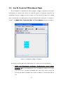
3.2. How To
T Creatte An IVY
Y Workbe
ench Plu
ugin
TThe IVY Workkbench is a modular
m
tool based on pluugins. A pluggin is integratted into the tool
t by
impleementing an interface that
t
defines the methodds needed for integratioon purposess. For
simpllification purposes a pluggin can also be called a tool. Each toool will be pllaced on a tabbed
pane so that the user
u can seleect between all the tools loaded into the frameworrk. For example, in
odel Editor, Propertiess Editor andd Traces An
nalyzer toolss are represeented.
Figuree 17, the Mo
Figuure 17 IVY Woorkbench Pluugins Framew
work.
TThe interfacee methods thaat must be im
mplemented to construct a tool are thhe following:
publlic void init(IServer
i
r coreServver, IToolP
Properties prop) th
hrows
Exce
eption thhis method innitializes the Tool. This method
m
is callled once in the life
cyclee of the tool. It receivess a parametter that is th
he server ussed to handle the
processing and also
a a param
meter that contains a refeerence to thee properties of
o this
tool.
25
public void initGUI(JFrame main, JComponent rootContainer) this
method is used to initialize the Graphic User Interface for the tool. This method is
also called once only in the life cycle of the tool. It receives the main JFrame of the
IVY Workbench tool and also receives the container in which the tool graphic
component can be added.
public void gainFocus() this method is to be invoked whenever the tool is
selected in the main tabbed pane of IVY Workbench tool. With this method we can
control what we want to do each time the tool gains control. For example if some
global data is changed by others tools then the current tool can also change its state
(by changing graphical elements or internal data) to reflect them.
public void loseFocus() this method is used whenever the tool loses the
control (is de-selected). With this method we can control what we want to do when
the user switches to other tool. For example the current tool can put some data in a
global area (common to all tools) so that the other tools can query if some global
data is available, and if so reflect some changes on their own states, by changing
graphical elements or internal data.
public boolean needsSaving() this method is used to tell if the tool needs to
save its data when a project is being saved.
public boolean needsFocus(int event) this method is used to return the
status related to focus. It receives a parameter that is the event by which the tool
needs focus. The event codes are the following:
o int EVENT_OPEN_PROJECT = 0;
o int EVENT_NEW_PROJECT = 1;
o int EVENT_SAVE_PROJECT = 2;
o int EVENT_CLOSE_PROJECT = 3;
o int EVENT_EXIT_PROGRAM = 0.
26
public void newProject(IProjectProperties proj) this method is invoked
whenever the main application creates a new project. It receives the project
properties (name, project working directory, author, etc.).
public void openProject(IProjectProperties proj, String[] files) this
method is invoked whenever the main application opens a project. It receives the
project properties and also the paths of the folders belonging to this tool.
public String[] saveProject(IProjectProperties proj) this method is
invoked whenever the user wants to save the current project. It will be up to the tool
to save its own data files. This method receives the project properties as a
parameter and returns the paths of the folders belonging to this tool.
public void closeProject(IProjectProperties proj) this method is invoked
whenever the IVY user wants to close the current project. It receives the project
properties.
public void exit() this method is invoked whenever the user exits the IVY
Workbench.
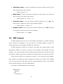
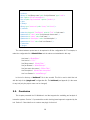
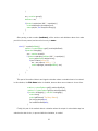
The configuration file plugin.xml is needed to properly configure the tool. The following text
explains how to fill the data fields of this configuration file.
The structure of the XML file is the following:
<?xml version="1.0" ?>
<!DOCTYPE plugin PUBLIC "-//JPF//Java Plug-in Manifest 0.4"
"http://jpf.sourceforge.net/plugin_0_4.dtd">
<plugin id=’tool name’ version=’tool version’ >
<requires>
<import plugin-id="CoreSystem"/>
</requires>
27
<runtime>
<library id=’tool library name’ path=’tool jar filename’ type="code">
<doc caption="API documentation">
<doc-ref path="api/index.html" caption="javadoc"/>
</doc>
</library>
<library type="resources" path="icons/" id="icons"/>
</runtime>
<extension plugin-id="CoreSystem" point-id="Tool" id=’tool name’>
<parameter id="class" value=’tool java main class name’ />
<parameter id="name" value=’tool name’ />
<parameter id="description" value=’tool description’ />
<parameter id="icon" value=’tool icon filename’ />
</extension>
</plugin>
The values between quotes have to be replaced to fill the configuration file. For example, to
make the configuration file of Model Editor tool the values are instantiated in this way:
‘tool name’= “ModelEditor”
’tool version’= “0.0.1”
’tool library name’= “Model Editor”
’tool jar filename’= “ModelEditor.jar”
’tool java main class name’= ”Editor.Editor”
‘tool description’= “Model Editor description”
‘tool icon filename’= “modelEditor.gif”
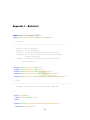
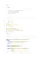
In the tool’s directory a “build.xml” file is also needed. This file is used to build the tool
with the help of the “plugin.xml” configuration file. The build.xml (see Appendix I) is the same
for any tool (only the project name can be changed).
3.3. Conclusion
This chapter presented the IVY Workbench tool that supports the modelling and analysis of
interactive systems. Section 3.1 presented the model checking based approach supported by the
tool. Section 3.2 described how to create a new plugin for that tool.
28
Chapter 4 – Related Work
This chapter describes CTTE (ConcurTaskTrees Environment) a task modeling tool that has
animation and simulation strategies that are similar to the ones intended to be used on the
proposed MAL models animator plugin. A previous IVY Workbench plugin - aniMAL - that had a
similar goal to this work will also be described.
4.1. CTTE
CTTE5 (see Figure 18) is an environment for editing and analysing task models. Its main goal
is to support the design of interactive applications focusing in the humans and their activities.
In [25] the concepts behind tasks models are presented. In is an important model because it
indicates the logical activities that an application can support. A task is defined as an activity that
should be performed by the user to reach a goal in the system. A goal can be a desired
modification of state or a query to obtain information on the current state of the system. Figure
19 presents an example of a Tasks model.
CTTE uses ConcurTaskTrees (CTT), introduced by Fabio Paternó in [26] and [27]. CTT is a
graphical notation (see Figure 20 for an example) with a set of operators used to describe the
relationships between tasks.
5
Available at http://giove.isti.cnr.it/tools/CTTE (last visited 27/10/2012).
29
Figure 18 CTTTE tool, takeen from [25].
Figure 19
9 An examplee of a task model,
m
taken from
f
[25].
30
Figure 20
0 Overview off the CTT nottation, taken from [28].
C
CTTE provides a simulaation functioonality that is describedd in [28]. TThe simulattion a
ConcurTaskTree involves simulating, in ssome way, the execution
n of specific tasks in ordder to
reachh a pre-defineed goal. In a ConcurTaskT
kTree, tasks are
a disposed in a hierarchhical style. That is,
depennding on whaat tasks havee been perforrmed, some tasks are enabled and otthers are disabled.
The ffirst step in simulating
s
CooncurTask-Trrees is to ideentify the taskks that are loogically enabbled at
the ssame time and that is called an enaabled task set.
s The set of all enableed task sets for a
specific task model is referred to as an enaabled task coollection (ETC
C).
C
CTTE’s taskss simulator is a basic onee (see Figure 21). It displaays the curreently enabledd tasks
in a list. Double-cclicking on a task will siimulate the performancee of that taskk. When a task
t
is
performed, the ennabled tasks are updated accordingly.
31
m [28].
Figure 21 A simplee ConcurTaskkTree task model simulator, taken from
C
CTTE is a goood case study on how a M
MAL models animator shoould functionn. The relevance of
the C
CTTE environment (see Figure 21) to tthe present work
w is its cooncept of enaabled tasks and
a its
simullation capabbilities. This concept annd the capabilities are described inn [28]. The main
differeences to the proposed WildAniM
W
pluggin will be the supported model (Taskks in one casse and
MAL models in the
t other), and also thatt we have attributes in the
t states of the MAL model,
m
someething that dooes not happen in CTTE.
It is expectedd that the WildAniMAL pluugin will havve a similar behaviour
b
to that of CCTE
E. The
actionns of the MAAL interactors will be reppresented byy similarly to CTTE tasks,, and the poossible
reachhable states (enabled
(
by a interactor aaction on a specific
s
statee) will be sim
milar to the ennabled
tasks of CTTE.
4.2. AniMA
AL
AAniMAL, desscribed in [2
29], is a prrototype of a plugin thaat was deve loped for thhe IVY
Workbench. Its most
m salient feeature is thatt of supportinng the definittion, at runtim
me, of a prototype
of thee interface too be used duuring the ani mation. It allows the association, to eeach attributte and
actionn, of a widget in order to create the prrototype.
TThe AniMAL tool obtains the data thaat it needs too perform its function from
m the CoreS
System
of thee IVY Workbbench. More specifically,, from the IModel (interractors modeel) data struucture.
IModeel data is updated by two
t other pl ugins of thee IVY Workbeench. The M
ModelEditor plugin
updattes it with model
m
data, which consiists of interaactors, attributes and acctions. The Traces
T
Visuaalizer plugin updates it with
w fail tracces (sequencces of states, defined bby their attributes’
values, representiing behaviours of the moddel).
32
W
What is intereesting and usseful in AniM
MAL is that it can generate a UI protottype from thee data
modeel it pulls from
m the CoreSyystem. It usees a mappingg generation strategy thatt can be autoomatic
or maanual. First it creates ann interactor tree from thhe data model. Then wee can opt beetween
choossing which graphical
g
elem
ments will reender each of
o the interactors’ attributtes and actioons, or
have the plugin perform
p
that mapping auutomatically. If we requesst for the maapping to bee done
autom
matically, theen the interacctors’ attributtes and actioons are rendeered with defa
fault components.
TThe default components’
c
rendering is as follows:
interactor – rendered
r
as panel;
attributes – rendered
r
usi ng the default widget for their type;
actions – renndered as buuttons.
If the mappinng is perform
med manuallly, we can choose the widget
w
that iss assigned too each
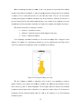
attribute. For exam
mple, for a temperature attribute we can use a th
hermometer (see Figure 22) to
show
w the changess in the tempperature valuee, as modelleed by the attribute.
Figure 22 The rmometer, taaken from [29].
TThe list of widgets
w
in AnniMAL is exttensible, which makes it very appeaaling to provvide a
graphhic evolution of the valuess of the attribbutes, insteaad of the tradditional repreesentations used in
thesee cases (e.g. State or Acctivity Diagram
ms). Theses widgets aree more famil iar and poteentially
providde an easierr insight intoo the behavioour of an innteractors moodel. Figure 23 presentss a UI
propttotype with the
t differentt widgets ussed for eachh of the attributes of aan Air-Condittioning
interaactors model.
33
Figuure 23 Protottype of an airr condition coontrol panel, taken from [[29].
AAniMAL’s animation capaabilities, how
wever, are lim
mited. The toool is only abble to animaate fail
tracess, That is different from
m what has been definedd as WildAnIMAL’s goal:: the capabiility to
animaate the interaactors modells themselvess.
4.3. Concllusion
TThis Chapterr described CTTE (ConccurTaskTreess Environmeent) a task modelling toool. A
previoous IVY Workkbench anim
mation pluginn - aniMAL – was also deescribed. Booth plugins provide
usefuul insights intto what the WildAniMAL
W
pplugin should be.
34
Chapter 5 – WildAniMAL
Implementation Approaches
This chapter discusses possible WildAniMAL implementation approaches. Section 5.1
discusses three implementation alternatives. Section 5.2 presents the chosen implementation
approach: NuSMV Simulation Capabilities.
The NuSMV model checker provides an interactive shell where commands can be entered.
The commands are grouped by the functionality they provide. There are eight main groups:
Model Reading and Building, Simulation, Checking Specifications, Bounded Model Checking,
Checking PSL Specifications, Execution, Traces, and Administration.
In the context of the present work, we are interested in those commands that help perform
an interactive simulation of a NuSMV specification. Having that in mind, the groups of commands
which are important to mention are: Model Reading and Building, and Simulation.
Sections 5.2.1 and 5.2.2 provide commands’ descriptions that are focused on those aspects
(options and environment variables) that are effectively used in this work. More detailed
descriptions can be found in [12].
Section 5.2.3 provides a NuSMV simulation example where all the presented commands are
used.
5.1. Implementation Approaches
In this Section, the main approaches to implementing the WildAniMAL plugin will be
analysed. Three approaches are considered. Section 5.1.1 looks at the possibility of generating
and using a Finite State Machine representation of the MAL interactors model to drive the
35
animation. Section 5.1.2 looks at using the BDD representation of the MAL interactors model
(created by NuSMV, the verification engine used by IVY Workbench) instead of creating our own
finite state machine. Finally, Section 5.1.3 looks at the possibility of using NuSMV's simulation
commands, available on its interactive mode, to perform the animation.
5.1.1 Generating a Finite State Machine
This approach can be described as transforming the MAL interactors model into a Finite
State Machine (FSM) model. An introduction to the theory behind FSM is available in Section 2.3.
To use this approach an algorithm to translate MAL models into some FSM representation
has to be developed and implemented. That work can be complex and time consuming and also
tests of the algorithm implementation's correctness are needed. Due to these reasons this
approach can be risky, and good results cannot be guaranteed beforehand.
The main advantage of this approach is that only the original MAL model is used, and the
results from the simulation process are easily interpreted in the context of, and incorporated into,
the MAL’s model iterative creation process. Other advantage is that, if this approach can be
efficiently implemented, then it will be as easy to perform an interactive simulation of the MAL’s
model (creating the FSM one step at a time) as it will the full generation of its FSM model.
Because the algorithm will be custom made it will be easily adaptable to any need desired.
To face this approach's risks, NuSMV's flat model FSM capabilities can be used. These
capabilities are supported by the following commands:
build flat model - Compiles the flattened hierarchy into a Scalar FSM;
build boolean model - Compiles the flattened hierarchy into boolean Scalar FSM;
write flat model - Writes a flat model to a file;
write boolean model - Writes a flat and boolean model to a file.
However, if the NuSMV FSM capabilities are used, then the main advantage stated above
can be lost, due to the translation process between MAL model and the NuSMV generated FSM
model. The simulation will no longer happen at the abstraction level of the MAL models, but at
the level of the NuSMV specifications created from those models.
36
5.1.2 NuSMV Binary Decision Diagrams
This approach can be described as using the BDD representation of the MAL interactors
model, created by the NuSMV model checker, to perform the animation.
Binary Decision Diagrams (presented in Section 2.4) are used by the NuSMV model checker
to perform model checking over the NuSMV model. These diagrams are not easily
understandable and can be difficult to use for the purpose of implementing the WildAniMAL
plugin.
This approach is not the best one because the initial MAL interactors model is translated to a
NuSMV model that is read by NuSMV model checker and transformed into BDD. Because two
translations steps are made, doing the analysis of the results obtained by animating the BDD,
and using them to help the modeling process of a MAL interactors model, will be a daunting task.
This is because several artificial variables can be added and transformations made between the
two models and the BDD.
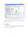
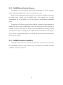
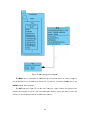
5.1.3 NuSMV Simulation Capabilities
The NuSMV model checker has simulations commands that can be used to help implement
the proposed MAL interactors model animator plugin. An example of the NuSMV’s simulation
capabilities is presented in Figure 24.
37
Figure
F
24 NuuSMV simulation examplee.
FFigure 24 shoows the available states at a given moment
m
in the simulatioon. The conccept of
Availaable States iss similar to thhe concept oof Enabled Taasks in CTTE. Enabled Taasks are calculated
whenn the CTTE’s user interacctively selectss a task to perform
p
and CTTE’S simuulator showss what
the nnext enabled (we can alsso say availaable) tasks are. Becausee the SMV M
Model is produced
from the MAL inteeractors moddel, in the IVYY Worbench tool,
t
it can bee used for sim
mulation purrposes
m
checkker. The NuSSMV commannds that can
n be used forr that purposse are
with tthe NuSMV model
the foollowing:
read_mo
odel Reads a NuSMVV fille into NuSSMV;
pick_sta
ate Picks a state from the set of innitial states;
simulate
e Perform
ms a simulatioon from the current
c
selected state;
TThe difficulty of this approoach is that these comm
mands must be invoked ffrom the proposed
WildAAniMAL plugin. However, the commannds are only available in interactive m
mode, and ass such
are not well suitedd to be calledd from an extternal processs.
38
Conceptually the main problem with this implementation approach is that the SMV Model is
slightly different from the initial MAL interactors model (as stated in Section 5.1.2). Therefore a
process of constant translation and interpretation of animation results from SMV model to MAL
model has to be made and that can be problematic and inefficient. Nevertheless, this is still
better than directly using BDDs (NuSMV uses the BDDs to run the simulation), were there would
be two steps between the original model and the representation our tool would use to support the
animation.
Considering the above, this approach was the chosen one for the implementation of the
WildAniMAL plugin.
5.2.
NuSMV Interactive Shell
The NuSMV Interactive Shell offers an interaction mode that initiates a read-eval-print loop, in
which commands can be executed. The activation of the shell is done by invoking the model
checker with the “-int” option:
system prompt> NuSMV -int <RET>
NuSMV>
When the default “NUSMV>” shell prompt is displayed, the system is ready to accept and
execute user commands.
A NuSMV command is a sequence of words. The first word represents the command to be
executed and the remaining words are its arguments. With the “set” command it is possible to
assign values to environment variables, which in turn influence the behaviour of the commands.
5.2.1 Model Reading And Building
The commands in this group are used for the parsing and compilation of the model into a
BDD and are the following:
read_model -í model-file. Reads a NuSMV file into NuSMV.
39
If the -i option is not specified, the command reads the file specified in the environment
variable Input_File. If the option is specified the command sets the environment variable
input_file to model-file, and reads the model from the specified file.
go - Initializes the system for verification.
This command is responsible for reading the model (unless it has already been read), and
generating a BDD from it. The model is first flattened, which includes instantiating modules
by substituting their actual parameters for the formal parameters, and then prefixing the
result with each particular instance’s name, scalar variables are encoded to create a boolean
model, and then the BDD is generated.
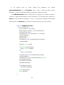
5.2.2 Simulation Commands
The commands in this group allow simulating a NUSMV specification and are the following:
pick state [ -i [-a] ]
Chooses an element from the set of initial states, and makes it the current state (replacing
the old one). The chosen state is stored as the first state of a new trace, which will grow in
number of states, as simulation evolves. The state can be chosen according to different
policies, which can be specified via command line options. By default the state is chosen in
a deterministic way.
Options:
-i enables the user to interactively pick up an initial state. The user is requested to
choose one state from a list of possible states. If the number of possible states is too
high, then the user has to specify some further constraints on the values of the variables
in the current state;
-a by default, states only show those variables that have changed from the previous
state. With this option, NuSMV displays all state and frozen variables regardless of
40
whether they have are changed and unchanged with respect to the previous state. This
option works only if the -i option has been specified.
simulate [-i [-a]] [-k steps]
Performs a simulation from the current selected state. The command generates a sequence
of at most steps states (representing a possible execution of the model), starting from the
current state. The current state can be set via the pick_state command.
Options:
-i enables the user to interactively choose every state of the trace, step by step. As
with pick_state, if the number of possible states is too high, then the user has to
specify constraints on the state attributes. These constraints are used only for a single
simulation step and are forgotten in the following ones.
-a again, this makes NuSMV display all the state and frozen variables (changed and
unchanged) during every step of an interactive session (which is not done by default).
-k steps this option defines the maximum length of the path to be generated. The
default value is determined by the default simulation steps environment variable
shown_states (ranges between 1 and 100, and default is 25).
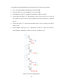
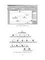
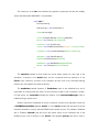
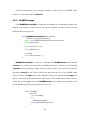
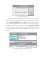
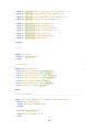
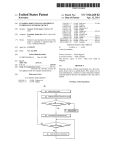
5.2.3 Simulation Example
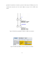
To illustrate the use of the NuSMV simulation commands a model of a garage gate will be
used. This model will be specified in the interactors language mentioned earlier in section 2.5.
This specification can be seen in Figure 25.
41
Figuure 25 Intera ctors model of a garage gate.
g
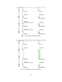
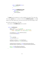
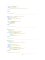
To understannd what this model
m
repressents we can see the statte diagram inn Figure 26.
Figure
F
26 Staate Diagram of
o gate modeel.
42
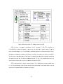
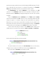
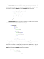
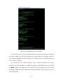
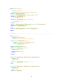
W
With the IVYY Workbench tool we caan compile the
t interactoors model, inn Figure 27, to a
NuSM
MV specification.
Figuree 27 NuSMV specificationn of the gate model.
H
Having this NuSMV
N
speccification it iss possible too simulate itt using the N
NuSMV interractive
modee. To start thee simulation we have to ddo the followiing:
ssystem prom
mpt> NuSMV -int gate.smvv
N
NuSMV> go
N
NuSMV>
43
TThe previous sequence of programs rreads the moodel to the NuSMV system
m. After doinng that
we haave to choose an initial sttate from thee possible initial states of the model. IIn our case we
w will
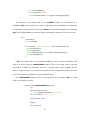
use tthe interactivve approach, in which thee user is able to interacttively choosee the states of the
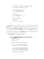
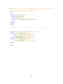
trace he wants to build. So wee have to usee the following command:
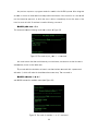
N
NuSMV> pic
ick state –ii -a
This ccommand haas the following result thaat is shown inn Figure 28.
Figure 28 The resuult of pick_staate –i –a com
mmand.
TThis result means that thiis model hass only one initial state, and because off that the state is
autom
matically chosen as the innitial state.
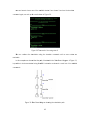
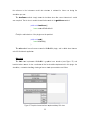
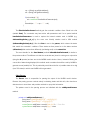
TTo proceed with
w the simulation we havve to use thee simulate coommand withh a parameteer k
with vvalue 1, whicch will make the simulatioon advance one
o step. Thee command iis:
N
NuSMV> sim
imulate -i –a
a -k 1
and N
NuSMV returnns the available states (seee Figure 29).
Figure 29 The result of simulate –i
– –a –k 1 coommand.
44
N
Now we havee to choose one
o of the avaailable statess. If we choosse 0 and usee the simulatee
comm
mand again, we end up thhe result shoown in Figure 30.
Figure 30 Thee result of choosing state 0.
W
We can conttinue the sim
mulation usiing the simuulate commaand until noo more statees are
reachhable.
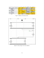
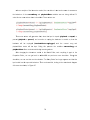
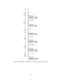
In this exampple we showeed that the paath, illustrateed in the Statte Based diaggram of Figure 31,
is posssible to be demonstrateed using NuSSMV’s Interacctive mode and
a a small set of its avaailable
comm
mands.
Figure 31 State
S
Based ddiagram show
wing the simu
ulation path.
45
5.3. Conclusion
In this chapter we described the NuSMV Interactive Mode and its available commands. To
more effectively illustrate it we presented a real example of a model: a garage gate. The model
was specified in the MAL Interactors language, compiled to a NuSMV specification, and finally a
simulation was carried out. That simulation used the commands that were previous presented.
We can conclude that NuSMV simulation commands can be useful to implement a MAL
Interactors model animator because the needed output and general mechanism is easily
available and ready to use.
46
Chapter 6 – WildAniMAL
Implementation
This chapter describes the implementation of WildAniMAL as a plugin for the IVY Workbench
tool. An architectural view with UML diagrams is provided. To provide more detail on the
implementation, an explanation of the main methods is presented.
6.1. WildAniMAL’s Architecture
Because the JAVA programming language was used, the architecture of the WildAniMAL
plugin can be easily explained by using UML diagrams for each of the Java packages created.
This scheme for presenting the architecture is well suited to provide the “main picture” of the
implementation.
47
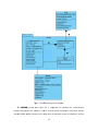
F
Figure
32 WilddAniMAL plu gin architectture as a pacckage diagram
m.
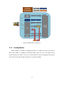
TThe architeccture of the plugin has five packagges (see Figgure 32): AAnimator (thee root
packaage), Traces,, NuSMV, Coonstraints andd Renderers. The plugin also
a dependss on the Tools and
Serveer packages of
o the IVY Woorkbench CorreSystem maain package.
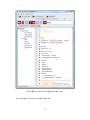
TThe Animator root packaage contains the following classes: Gui,
G Main, TTreeActionss and
Parsser. These classes interacct with the innner packagees of Animatoor package, aas it will be shown
s
next.
48
Figure
F
33 Maain package class
c
diagram
m.
TThe Main class is responsible for im
mplementing the interfacee needed to ccreate a pluggin for
the IVVY Workbench tool as expplained in Secction 3.2. In particular, it initializes thee Gui class, in the
initG
Gui method of
o the interfacce.
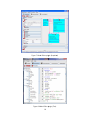
TThe Gui classs (see Figurre 33), as thhe name maay give a clu
ue, handles tthe graphicaal user
interfface of the plugin. It has the code forr displaying the
t buttons, panels and ttables, used in the
h
the events
e
for thee buttons preesses.
interfface. It also handles
49
Figgure 34 NuSSMV package class diagraam.
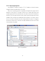
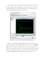
TThe NuSMV
V package (see
(
Figure 34) is respponsible for handling thhe communication
betweeen the graphical user intterface, in whhich the userr can select simulation
s
coommands, annd the
externnal NuSMV model
m
checkker process ((that works inn interactive mode as exxplained in Section
50
5.2). It uses the Parser classs to parse the states contained
c
in the results oobtained from the
NuSM
MV model chhecker proceess. These sstates, obtainned in each simulation sstep from NuuSMV,
feed a JList. Whenn the states are
a parsed itt is possible to
t see the infformation asssociated withh each
of theem in anotheer JList (StateeInfo).
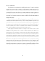
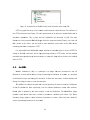
Figuure 35 Constrraints packagge class diaggram.
TThe Constra
aints packagge (see Figurre 35) has thhe function of
o enabling W
WildAniMAL too filter
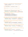
the sstates obtainned from NuSMV basedd on the vaalues of theeir attributess. In each of
o the
simullations stepss, the user has to choosee a current state
s
from th
he set of all possible staates at
that point in thee simulation. This set ccan become large. Hencce, filtering the states with
w a
conjuunction of connditions on the values of their attributtes, helps the user focus on the statees that
matteer at each paarticular mom
ment, and alsso helps him
m choose the right state too proceed wiith the
simullation.
PPackage Ren
nderers is responsible foor rendering the states th
hat meet thee constraints of the
filter. Currently, thhat is done by changing thhe background color.
W
When the fuuture states of a simulaation are moore than one hundred, NuSMV doees not
produuce the list of possible states.
s
In th is case, “To
oo many States” appeears in stateList.
51
Then, constraints have to be entered to ffilter the stattes (here at the
t level of tthe NuSMV model
checkker process) in order to obtain the staates’ list needded to proceeed with the ssimulation.
Figure 36 Tracces package class diagram.
TThe Traces package (seee Figure 36) is responsibble for showin
ng the states resulting froom the
simullation. This iss achieved with
w the help of visual reppresentationss. These visuual representtations
are tw
wo of the ones
o
already available inn the Tracess Visualizer plugin of thee IVY Workbbench:
State
teBased andd Tabular, and their impplementation is described in [24]. Theey were adappted to
receivve states onee by one, beecause the trrace is createed step by step as the u ser is entering his
choicces in the inteeractive simuulation. In th e Traces Visualizer plugin
n the trace iss fully formed with
all staates and is displayed prom
mptly.
W
When a new state is parrsed in the P
Parser classs, a method (addState) is called inn each
visual representattion that addss the state innfo and does what is needded to updatte the drawn visual
repreesentation, so
s that it reeflects the nnewly addedd state information. In the case of
o the
52
StatedBased representation, the update is done by calling drawInteractorState (which
performs a repaint).
It’s easy to add more visual representations because the main class of a representation will
only have to implement the addState method, and the graphical (or textually, if wanted)
representation. This feature makes the plugin extensible regarding the visual representations
available.
6.2. WildAniMAL’s Source Code Description
This section presents a description of the most relevant aspects of the implementation’s
source code. That description will be grouped by the packages described in the previous section.
6.2.1 Animator Package
Class Main
As already mentioned, the Main class implements the plugin interface of the IVY Workbench
tool.
public class Main implements ITool {
/** container for application. */
private JComponent container = null ;
/** application core server. */
private IServer server = null;
private Gui frame;
private IModel model;
public Main() {
frame= new Gui();
frame.saveLastFileModified();
}
The previous code shows that the Main class implements the ITool interface, that is, the
plugin interface of the IVY Workbench tool. The variables container and server relate to the
CoreSystem of the IVY Workbench tool, and enable the plugin to communicate with it. In
particular, they enable the WildAniMAL plugin to retrieve information from the shared data
53
structure used by all the plugins of the tool. It is through this shared information that the plugin
integrates its own functionalities (in this case, the simulation of the interactors model - using the
NuSMV specification as an intermediate representation) with the rest of the tool. The model
variable will hold all data from the interactors model and is used to retrieve information needed to
construct constraints and also to help the NuSMV package classes perform their function.
The Main() constructor initializes the GUI class which, has its name indicates, is the
Graphical User Interface of the plugin. The saveLastFileModified method is used to store in a
variable the last time when test.smv (the SMV Specification file) was modified. That information
will be used to test when a new model was compiled in the Properties Editor. Whenever a new
interactors model is compiled, the WildAniMAL simulation has to be restarted.
Another method that is used during the initialisation of the plugin is initGUI.
public void initGUI(JFrame main, final JComponent rootContainer) {
this.container = rootContainer;
container.setLayout(new BorderLayout());
container.add(frame,BorderLayout.CENTER);
}
The method simply adds WildAniMAL’s graphical user interface (given by the GUI class as
frame variable) to the JComponent (rootContainer) that has been assigned to it by the Core
System. Each plugin is graphically located in a tab.
Next the handling of focus must be provided.
public void gainFocus() {
frame.checkFileModifications();
CServer i=(CServer)server;
model=i.getModel();
frame.setIModel(model);
}
The gainFocus method is executed whenever the user chooses the plugin WildAniMAL in
the IVY Workbench tool (by clicking in the respective tab). In this method, a check is made to
determine if a new interactors model was compiled, in which case the simulation will be
restarted. That is done by using the checkFileModifications method of the Gui class. Also,
54
the rreference to the interacttors model data structuure is retrievved for futurre use durinng the
simullation processs.
TThe loseFoccus method simply storees the last time
t
when th
he current innteractors’s model
was ccompiled. That is done to enable the vverification made
m
in the gainFocus
g
m
method.
public void loseeFocus() {
frame.saveeLastFileModified();
}
FFinally the exxit behaviour of the pluginn must be proovided.
public void exitt() {
frame.killN
NuSMV();
}
TThe exit metthod frees all resources uused in WildAAniMAL plugin, and is callled when thee user
exits IVY Workbennch applicatioon.
C
Class Gui
TThe Gui claass implemeents WildAniM
MAL’s graphhical user in
nterface (seee Figure 37
7) and
handles buttons events.
e
It also coordinatees all the functionalities im
mplemented in this plugin: the
simullation, constrraints handlinng, drawing oof traces visuual representations and fi lters.
Figure 37 Graphical userr interface im
mplemented by
b GUI class..
55
The constructor of the Gui class initializes the graphical components and also the auxiliary
classes that will handle WildAniMAL’s functionalities.
public Gui() {
initComponents();
GridLayout gd = new GridLayout(0,1);
cPanel.setLayout(gd);
model = (DefaultListModel) statesList.getModel();
parser = new Parser(model, statesList);
treeActions = new TreeActions();
nusmv = new NuSMVInteractiveRun("test.smv", Consola, parser);
constraints = new ConstraintsManager(cPanel, treeActions);
stRenderer = new StatesRenderer();
statesList.setCellRenderer(stRenderer);
stateBased = new StateBased(stateBasedPanel);
tabular = new Tabular(tabela, scrollTabela);
}
The statesList variable (a JList) holds the current states returned on each step of the
simulation. A reference to its model (data) and the component itself are passed on in the
Parser class constructor, because in the simulation process, and in the associated parsing
needed, this class updates the states list directly.
The treeActions variable (instance of TreeActions class) is also initialized here, and is
responsible for storing locally the actions of the interactors model to help constraints’ creation.
For that reason, the constraints variable (an instance of the ConstraintsManager class) is
initialized using a reference to it.
Another class that is instantiated in the Gui constructor, and the most important of them all,
is NuSMVInteractiveRun (variable nusmv). It is the nusmv variable that will setup the actual
interactive simulation, using an external NuSMV model checker process. The variable is initialized
with a JTextarea (Consola) that will receive the textual output of the commands sent to the
NuSMV process, with a reference to the Parser class (variable parser) that will be used to
56
parse that same output, and with the name of the file holding the NuSMV specification. This file’s
name is hardcoded (by choice) because it is a temporary file generated in the Properties
Editor plugin of IVY Workbench when the current interactors model is compiled.
The StatesRenderer class (variable stRenderer) is also instantiated in the GUI
constructor. It is the stRenderer variable that will be responsible for showing the result of
filtering the elements of statesList (by changing their background color) when some constraints
are applied.
Finally, the StateBased (variable stateBased) and the Tabular (variable tabular)
classes are also instantiated in the Gui constructor. The two corresponding variables will enable
showing the progress of a simulation, through the visual representations they implement.
Whenever the user chooses a state to proceed with the simulation, these two variables receive
that information which will be shown with the corresponding graphical strategy. The stateBased
variable provides a kind of state diagram and the tabular variable provides a normal table.
Next the method that shares the interactors model (IModel variable), between all the
variables that need it, is provided. These variables are: nusmv, constraints and treeActions.
public void setIModel(IModel mod) {
imodel = mod;
nusmv.setImodel(mod);
constraints.setChoices(imodel);
treeActions.changeTree(imodel);
}
Next the methods that handle button events are presented.
private void btGetFirstStateActionPerformed(java.awt.event.ActionEvent evt) {
nusmv.sendCommand("pick_state -i -a");
btGetFirstState.setEnabled(false);
}
This method handles the click event on the Get Initial State button, and does that by
sending the shown command to the NuSMV model checker (using the nusmv variable).
Next, another button’s (Pick State) event handling is provided.
private void btPickStateActionPerformed(java.awt.event.ActionEvent evt) {
int index = statesList.getSelectedIndex();
if (index != -1) {
57
//Add State to the Trace Visualizer
stateBased.addState(""+index, parser.getStateInfo(""+index));
tabular.addState(parser.getStateInfo(""+index));
//SendCommand to show next states
if (statesList.getModel().getSize() > 1)
nusmv.sendCommand(""+index);
model.clear();
nusmv.sendCommand("simulate -i -a -k 1");
stRenderer.clearStates();
//Update Trace Visualization
stateBasedPanel.repaint();
tabela.repaint();
interactorsNamesPanel.repaint();
}
}
This method picks up the current state choice, that is, the selected number in the
statesList JList. If a choice exists (not null) then the respective state info is added to the traces
visual representations (stateBased and tabular variables). After that, the choice (state number)
is sent to NuSMV model checker and statesList is cleared. Then, the simulate command is
sent to NuSMV which will return states to fill statesList again. Finally repaints are made in order
to show the state update in the trace’s visual representations.
Next the Filter button event handling is provided.
private void filterActionPerformed(java.awt.event.ActionEvent evt) {
JPanel constPanel;
JComboBox vars, op, vals;
String var, opc, val;
ArrayList<String> lista = new ArrayList<String>();
for (int i = 0; i < cPanel.getComponentCount(); i++) {
constPanel = (JPanel) cPanel.getComponent(i);
vars = (JComboBox) constPanel.getComponent(0);
op = (JComboBox) constPanel.getComponent(1);
vals = (JComboBox) constPanel.getComponent(2);
var = (String) vars.getSelectedItem();
58
opc = (String) op.getSelectedItem();
val = (String) vals.getSelectedItem();
if (val.contains("(")) {
val = treeActions.handleActionParameters(val);
}
lista.add(var + " " + opc + " " + val);
}
The filterActionPerformed method gets the constraint conditions from cPanel into a list
(variable lista). The constraints may have action with parameters and if so a special method
handleActionParameters is used to replace the internal notation used in NuSMV (e.g.
doSomethingAction_a_b_c) by the more user friendly notation used in MAL models
(doSomethingAction(a,b,c)). After that lista is sent to the parser, which returns the states
that match the constraints’ conditions. These states are then passed on to the states renderer
(stRenderer) that renders them differently (red background) on the statesList.
The event handler for the Send button (method btSendActionPerformed) is similar to
the previous method. The difference is that the constraints are joined in a string as a conjunction
(using the & operator) and are sent to the NuSMV model checker. Hence, instead of filtering the
current list of states being displayed, this method sends constrains that will be used by NuSMV to
generate a new (smaller) list. This is particularly useful when the list of possible states is too big
(over 100 states) in which case NuSMV will not generate it.
Class Parser
The Parser class is responsible for parsing the output of the NuSMV model checker.
Because the parsing process consists mainly in obtaining states and their info, this class has a
data structure to store them and provides methods to query that information.
The patterns used in the parsing process are initialised with the addSystemPatterns
method.
private void addSystemPatterns() {
String ident="([a-zA-Z][a-zA-Z0-9_$~.><\\[\\]\\-]*)";
String value="([a-zA-Z0-9_$~.><\\[\\]\\-]*)";
systemPatterns.add(Pattern.compile("(\\d+)\\)")); // State filter
systemPatterns.add(Pattern.compile("(\\s*)"+ident
59
+ "(\\s*)=(\\s)*(\\d)*" + value)); // Action\Atribute Filter
systemPatterns.add(Pattern.compile("\\s*Set of future states is EMPTY: "
+ "constraints too strong\\? Try again.\\s*")); // Set of Future States Empty
systemPatterns.add(Pattern.compile("\\s*Too many \\([0-9]+e\\+[0-9]+\\) "
+ "future states to visualize. Please specify further constraints: \\s*"));
// To Many States After Constraint Send
}
The addSystemPatterns method compiles the patterns (regular expressions) used in
the parsing process of the NuSMV model checker’s output. The first pattern matches a state
number. The second pattern matches an action or attribute value (that is part of state info). The
third pattern matches the indication that after applying constraints there aren’t any states to
proceed with simulation. The last pattern matches the indication that applied constraints aren’t
sufficient and more have to be specified.
The parseLine method is responsible for parsing a line of the NuSMV model checker’s
output. The parsing is done by identifying specific keywords and patterns in the text produced by
NuSMV. The first part of this method checks if the line contains “AVAILABLE STATES”, which
means that a new simulation step has started (a state has been chosen). In that case the states
structure is cleared to receive new states info.
public void parseLine(String lineRead) {
if (lineRead.contains("AVAILABLE STATES")) {
availableStates=true;
states = new HashMap<String,ArrayList<String>>();
Gui.setBtPicksState(true);
}
Next the method checks if the line contains a new state number. If so, then it also tests if the
model was on a situation where constraints insertion was needed. Then the state number is
added to states. That state number is also stored in an auxiliary variable lastState.
String aux;
if (availableStates) {
matcher = systemPatterns.get(0).matcher(lineRead);
if (matcher.lookingAt()) {
if (model.contains("Too Many States")) {
model.removeElement("Too Many States");
Gui.setConstraints(false);
60
}
aux = matcher.group(1);
lastState = aux;
if (!model.contains(aux) && !"".equals(aux)) {
model.add(Integer.parseInt(aux),aux);
states.put(aux, new ArrayList<String>());
}
}
After parsing a state number (lastState), all the actions and attributes values that make
part of its info are parsed, and stored in its entry in states.
else if (!"".equals(lastState)) {
matcher = systemPatterns.get(1).matcher(lineRead);
if (matcher.lookingAt()) {
aux = matcher.group(0);
if (states.containsKey(lastState) && !"".equals(aux)) {
states.get(lastState).add(aux.trim());
if (aux.contains("action")) {
aux = aux.replace("action = ","");
model.set(Integer.parseInt(lastState), aux);
}
}
}
}
This part of the method detects and signals a situation where constraints have to be entered.
In this situation, the Pick State button is disabled, because there are not states to choose from.
matcher = systemPatterns.get(2).matcher(lineRead);
matcher1 = systemPatterns.get(3).matcher(lineRead);
if (matcher.lookingAt() || matcher1.lookingAt()) {
model.clear();
model.addElement("Too Many States");
Gui.setConstraints(true);
Gui.setBtPicksState(false);
}
Finally, this part of the method detects a situation where the output for a simulation step has
ended and a state choice, to proceed with the simulation, is needed.
61
if (lineRead.contains("Choose a state form the above") ) {
availableStates = false;
lastState = "";
Gui.setBtPicksState(true);
}
}
6.2.2 Constraints Package
The ConstraintsManager class is responsible for managing constraints that can be sent
to the NuSMV model checker or used to filter states. This class constructor is initialized with the
constraints JPanel (see Figure 28), and with a reference to an instance of the TreeActions class
that will help with retrieving information on the actions in the interactors model.
The setChoices method (some parts of the code are presented) fills the variables choices
(all names of attributes and variables in the interactors model) and valuesList (the
corresponding values for any variable in choices).
for (int j=0; j<v.size();j++ ) {
elem=v.get(j);
aux = new ArrayList<String>();
def=model.getDef(elem);
if (!def.equals("")) {
if (def.contains("array")) {
choices.remove(choices.size()-1);
aux=model.getAttributeValuesOnly(elem);
valuesList.put(elem,aux);
}
else if (defs.containsKey(def))
valuesList.put(elem, defs.get(def));
else {
aux=model.getAttributeValuesOnly(elem);
valuesList.put(elem,aux);
defs.put(def,aux);
}
choices.add(elem);
}
}
62
In
the
method,
when
an
action
variable
has
parameters,
the
method
getInstantiatedActions of the TreeActions class is used, to unfold the types of these
parameters, in order to obtain all the possible combinations of parameter values.
The addNewConstraint method is responsible for creating a new constraint condition. A
constraint is graphically represented by three combo-boxes. The first holds all the elements of
choices, the second holds the operators (“=” and “!=”), and the last is updated with all possible
values (values from valuesList) for the element currently selected on the first combo-box.
public void addNewConstraint() {
if (choices.size() > 0) {
JPanel constraint = new JPanel();
ArrayList<String> operators= new ArrayList<String>();
ArrayList<String> values;
JComboBox vars= new JComboBox(choices.toArray());
constraint.add(vars);
operators.add("=");
operators.add("!=");
JComboBox op= new JComboBox(operators.toArray());
constraint.add(op);
String key = choices.get(0);
if (valuesList.containsKey(key))
values = valuesList.get(key);
else
values = new ArrayList();
JComboBox vals= new JComboBox(values.toArray());
constraint.add(vals);
ComboListener cl = new ComboListener(vals,valuesList);
vars.setSelectedIndex(0);
vars.addActionListener(cl);
op.setSelectedIndex(0);
if (vals.getItemCount()>0)
vals.setSelectedIndex(0);
painel.add(constraint);
painel.updateUI();
}
}
63
A textual representation of the constraint condition is what is sent to the NuSMV model
checker, or used to filter states in statesList.
6.2.3 NuSMV Package
Class NuSMVInteractiveRun is responsible for handling the communication between the
graphical user interface, in which the user can execute simulation commands, and the external
NuSMV model checker process.
public NuSMVInteractiveRun(String nusmvFile,
JTextArea consola1,Parser parser1){
console = new NuSMVConsole(nusmvFile,consola1,parser1);
console.loadConsole();
input = new Input(console);
console.setInput(input);
input.start();
console.execCommand("go");
}
NuSMVInteractiveRun’s constructor instantiates the NuSMVConsole class (variable
console) with a reference to the file with the NuSMV specification, a reference to the JTextArea
(consola1) that will receive the output from the model checker process, and also a reference
(parameter parser1) to the Parser instance that will parse each line of the NuSMV model
checker’s output. The Input class is also instantiated, which starts a thread (variable input) that
will be continuously reading data from the input stream of the NuSMV model checker process.
Finally, the command go is sent to the NuSMVConsole, and it initializes the simulation of the
current NuSMV specification (as explained in section 5.2.1).
public void run() {
while(true) {
console.readChar();
try {
waitWhileSuspended();
} catch (InterruptedException ex) { }
}
}
64
public void setPaused(boolean p) {
this.paused = p;
}
private void waitWhileSuspended()
throws InterruptedException {
while (paused) {
Thread.sleep(200);
}
}
The Input thread can be paused, if no data is available in the stream. That is done with a
state variable (paused) that is constantly checked (with waitWhileSuspended), in the run
method of this thread. Without this, the process would be kept active while waiting for input,
which would create a big impact in CPU usage.
Next methods of the NuSMVConsole class are provided.
public void loadConsole() {
String[] cmdarray = {"","-int", nusmvFile};
cmdarray[0] = ""+System.getProperty("user.dir") + File.separator +
"NuSMV" + File.separator + "bin" + File.separator + "NuSMV";
ProcessBuilder pb = new ProcessBuilder(cmdarray);
pb.redirectErrorStream(false);
try {
proc = pb.start();
} catch (IOException ex) { }
InputStream inputStream = proc.getInputStream();
OutputStream outputStream = proc.getOutputStream();
InputStreamReader inputStreamR = new InputStreamReader(inputStream);
OutputStreamWriter outputStreamW = new OutputStreamWriter(outputStream);
brInput = new BufferedReader(inputStreamR);
bwOutput = new BufferedWriter(outputStreamW);
}
65
The loadConsole method sets NuSMV’s command path, which has to be inside IVY
Workbench application path and more specifically in NuSMV/bin/NuSMV, and starts a java
process with it. Then its input (brInput) and output (brOutput) streams are retrieved.
void execCommand(String command) {
input.setPaused(false);
try {
bwOutput.write(command);
execNewLine();
} catch (IOException ex) {
}
}
The execCommand method is used to send a command to the NuSMV process. Each time
it is executed it starts by activating the Input thread (awaking it).
void readChar() {
int c = 0;
char ch = 0;
try {
c = brInput.read();
if (c == -1) {
input.setPaused(true);
parser.selectFirstState();
return;
}
ch = (char) c;
} catch (IOException ex) { return; }
The readChar method will read a character at a time from brInput. This has to be done in
this way (the usual way is to read line by line) because sometimes the NuSMV process does not
print the last line of result, for example when it is waiting for the user to choose a state and
subsequently to press enter (newline). When brInput returns no char (a value equal to -1), then
Input thread is paused and readChar methods returns immediately.
if (ch=='\n') {
str = sb.toString();
parser.parseLine(str);
66
sb = new StringBuffer();
consola.append(str+"\n");
consola.setCaretPosition(consola.getDocument().getLength());
}
The characters consecutively read by the readChar method are accumulated in a
StringBuffer (sb), until a newline (\n) is read. In that situation, the stringBuffer is transformated
in a String (the read line), which is sent to the Parser to be parsed and printed in the JTextArea
Log. The StringBuffer sb is also cleared to begin accumulating characters to form the next line.
else {
sb.append(ch);
aux = sb.toString();
if (aux.matches(" action = [a-zA-Z0-9]+") && containsAction(aux)) {
parser.parseLine(aux);
consola.append(aux);
consola.setCaretPosition(consola.getDocument().getLength());
sb = new StringBuffer();
}
If ch is not newline then it is accumulated in sb. Then a test is made to determine if the
string is an action (using the containsAction method). This is the strategy used to overcome
the problem of NuSMV not printing the last line of command output, which originates the last
action of a state’s result of a command not being parsed. This strategy works because the action
is the last line printed by NuSMV in any state attributes listing.
The containsAction method checks if a string passed as a parameter (aux) is a valid
action in the interactors model.
private boolean containsAction(String aux) {
try {
ArrayList<String> actions =
imodel.getActionsVariable("main.action");
aux = aux.replace(" action = ","");
boolean match = false;
String ac;
aux = aux.trim();
67
String encontrada = "";
for(String act: actions) {
ac = act.trim();
if ( ac.compareTo(aux)==0 ) {
match = true;
encontrada = ac;
break;
}
}
If an action is encountered (match is true) then an additional test is made. This handles the
situation when one action has a name that starts with another action name. For example:
setValueMCP and setValue. If this verification is not performed, then if the correct action to be
matched is setValueMCP, what is (wrongly) matched is setValue.
if (match) {
for(String act: actions) {
ac = act.trim();
if (ac.contains(encontrada) &&
ac.length() > encontrada.length())
return false;
}
}
return match;
}
catch (Exception e) {
return false;
}
}
6.3. Conclusion
This chapter described the implementation of WildAniMAL as a plugin for the IVY Workbench
tool. Section 6.1 presented a high level view of how the implementation code was organized. As
the work of implementation was a Java programming task, this was explained with UML class
diagrams, showing how classes were organized into packages.
68
Section 6.2 makes an extensive explanation of the code. One reason to do that is to fully
present some problems that were encountered during development, and how they were
overcome. By explaining the implementation in detail, it becomes easier for anyone to
understand the code and consequently improve it at a later occasion. This also made it possible
to think about how some implementation choices were made, and in the task of writing the
explanation to describe this code, some methods were implemented in a more efficient way.
69
Chapter 7 – Using WildAniMAL
This chapter demonstrates the WildAniMAL plugin of the IVY Workbench tool. Section 7.1
presents a simulation example that makes extensive use of all the functionalities available in the
plugin. Section 7.2 presents the conclusions of this chapter.
7.1. WildAniMAL’s Usage Example
To explain how the WildAniMAL plugin can be used, a small example of an Ipod-like music
player will be introduced. To be able to keep the explanation short and understandable, some
aspects of the real device will be abstracted in order to work with a simpler model.
First an interactors model of the device will be created using the Model Editor plugin of the
IVY Workbench (see Figure 38).
70
Figure 38
8 Ipod modell creation witth Model Edittor plugin.
TThe full interaactors modell is presentedd in Appendixx II.
71
AAfter the moddel’s creationn, it has to bbe compiled to
t a NuSMV specificationn. That is achhieved
in thee Properties Editor
E
plugin of the IVY W
Workbench. To perform that compilatioon we have too click
in thee “bug” buttoon (near the “X” button) oof the Properties Editor. If the compilaation is succcessful
then tthe respectivve NuSMV sppecification iss shown (see Figure 39).
Figuree 39 Ipod intteractor modeel compilatioon with Propeerties Editor pplugin.
N
Now we can really start simulating
s
thhe NuSMV sppecification, which
w
is the interactors model
interm
mediate reprresentation. When
W
in WlddAniMAL, thee first thing to
t do is clickk the “Get Initial
I
Statee” button (see Figure 40
0). That opeeration results in a list off available innitial states. These
statess can be accessed from the Actionss list. Note that in this case
c
the list will only have nil
actionns, one for each
e
possiblee initial state , since no acction is perfoormed to reaach the initial state
(remeember that thhe nil action represents a state transiition without an associateed action).
72
Figure 40 Reesult of presssing “Get Inittial State” in WildAniMAL .
In the currennt model, thhere is only one initial state (nil acction) to chooose. That state’s
s
attributes can be looked up inn the State Info list (seee Figure 40)) by selectingg the action in the
Actio
ons list. To choose the state we haave to click the
t “Pick An Action TTo Go To A New
Statee” button.
73
TTo perform thhe interactivee simulation, we simply have
h
to continuously chooose an actionn from
the A
Actions list. Each time thhe “Pick …”” button is clicked,
c
a new
w list of actioons appears.. Each
one leeading to a new
n state.
In this example, if the acctions: nil aand plugHea
adsets, are chosen, in tthat order, then
t
a
situattion is reacheed, in which it is not posssible to conttinue with thee simulation,, as it can bee seen
in Figgure 41. Afteer plugHead
dsets, the lisst of possiblee future statees is too largge (more thaan one
hundred possible states). In thhat case, thee actions list presents onlyy one elemennt, which inddicates
that tthere are “Tooo Many Statees”.
Figure 41 Simulation
S
reaached a “Tooo Many Statees” situation.
In this case we might want
w
to look at the sequuence of the actions exeecuted so far. The
sequeence of actioons and stattes of the innteractive sim
mulation can
n be shown as a State based
diagraam (see Figuure 42), using a Tabular representatioon (see Figurre 43), or as a textual Log (see
Figuree 44). The State Basedd diagram aand the Tabble are visuaal representaation of the trace
74
generrated in the simulation.
s
The
T textual LLog shows the details (output of NuSM
MV process) of the
comm
munication (commands
(
and their rresults) betw
ween the plugin and thhe NuSMV model
checkker.
Figure 42 State Based represenntation of thee trace createed in the sim ulation.
Figure 43 Tabulaar representaation of the trrace created in the simulaation.
75
Figurre 44 Log reppresentation of the simulation.
In Figure 44, we can see that the currrent simulation reached a situation w
where there are
a too
manyy futures stattes to choosse from (morre than one hundred, thaat is the maxximum number of
futuree states thatt NuSMV cann handle). Inn this case, constrains have to be enntered and that
t is
done as shown in Figure 45.
TThe constraints can be created using the + annd – buttons, to add aand remove them,
respeectively. When all constraaints are creaated, they arre sent to thee NuSMV moodel checker using
the “S
Send” buttoon. If the connstraints are successful in the job of reducing thee number of future
statess, then a new
w actions list is available tto continue the
t simulation. That is thhe current caase, as
show
wn in Figure 46.
4
76
Figure 455 Constraintss insertion.
O
Once the connstraints (seee Figure 45) have been successfully
s
sent, and a new actions list is
returnned (see Figgure 46), an irregular sittuation occurs. When filttering the acctions list with the
consttraint action
n = unplug
gHeadsets, using the Filter
F
button, we can seee that this action
leadss to two statees. The problem is that oone of these makes no seense, becausse it means that if
the hheadsets are unpluged frrom the Ipodd, then the new value of
o headsetssState is plu
uged.
Basiccally it meanns that if heeadsets are unpluged, they remain pluged. Beccause that cannot
c
happeen in real world,
w
the original
o
interaactors modeel probably has an erroor and has to be
corrected.
Figure 46
4 Result of aapplication off the constraints sent.
77
AAfter an analysis of the innteractors moodel, the connclusion is th
hat under som
me circumsttances
the bbehaviour of the curren
ntSong and playbackS
State variables was not being defineed. To
solve this two new
ws axioms haave to be addded. These axxioms are:
TThese new axioms
a
will guarantee
g
thaat, when thee Ipod is stoped (playbaack = stope
ed) or
pauseed (playbacck = paused), and an aaction to unnplug the heaadsets is ca rried on, theen the
headssets will be
b unplugedd (headsettsState=unp
plugged) and
a
the cuurrent songg and
playbbackState states will bee kept. Doiing this preevents the variables cuurrentSong
g and
playb
backState from
f
non-deterministicallyy assuming values.
v
AAfter changinng the interaactors modeel in the Moodel Editor, and
a compilinng it again in the
Propeerties Editor,, we can goo back to W
WildAniMAL to
t perform a new simuulation. Doingg that
simullation, we caan see that now the situattion “Too Maany States” no
n longer apppears and thhat the
Ipod model has thhe expected behaviour. TThat can be verified,
v
looking to the staate based diaagram
of thee new simulaation, in Figurre 47.
78
Figuree 47 State Baased represeentation of a trace
t
originatted in a simuulation.
79
7.2. Conclusion
This chapter presented an interactors model of an Ipod-like device. It was shown how that
model can be created, compiled to a NuSMV specification and simulated with WildAniMAL.
We demonstrated how WildAniMAL can be useful in the task of detecting bugs and errors in
an interactive manner. The situation (error in the model) that was presented and corrected was
representative of other similar situations that can occur in other models.
What is important to retain is that we can easily validate an interactors model and see if it
behaves how we expect it too. If that does not happen, then we can use WildAniMAL
functionalities to find out why. Doing this early validation is useful, because we can construct the
interactors model incrementally by validating some steps at a time, instead of creating the big
model and verify it as one.
80
Chapter 8 – Conclusions and
Future Work
This chapter summarizes the work done and all results achieved. Some future work can be
done in order to improve this WildAniMAL plugin, and therefore the aspects that can be worked
on are also presented.
8.1. Goal
The goal of this work was to develop a plugin to help an IVY Workbench user while creating
an interators model to interactively explore its behaviour: that is, enable the user to manually
trigger events and observe how the model evolves. WildAniMAL (Watch It vaLiDation Animator for
MAL) can perform this. It assists the modelling and analysis process, by providing functionalities
to simulate and validate the model being created.
8.2. Results
In order to implement the plugin, three possibilities were studied (see Chapter 5):
a. representing a MAL interactors model as a Finite State Machine (FSM) and use that to
drive the animation;
b. use the BDD (Binary Decision Diagrams) representation of the MAL interactors model,
created by the NuSMV model checker, to perform the animation;
c. use the NuSMV model checker simulations commands, available on its interactive mode,
to perform the animation.
81
After an analysis of the different alternatives it was decided to use the NuSMV’s simulation
capabilities in the implementation of WildAniMAL. The implementation is described in Chapter 6.
The implemented plugin supports the animation of models as intended. At each step the
user can select one of the available actions and the animator presents the state (or possible
states, in case of non-determinism) resulting from that action.
During the process of implementing the plugin, problems related to existence of nondeterminism in the models arose. These related both to NuSMV not generating the list of possible
future states, after a transition, if the number of states in the list exceeds one hundred, and also
because even if the list of possible states is less than one hundred, it might be too large for a
human user to analyse it. These issues were solved with the introduction of constraints to delimit
the effect of actions in the state of the system, and thus reduce non-determinism in the
simulation.
A first result of this dissertation is that the goal of this work, recalled in the previous Section,
has been achieved as is demonstrated by the example presented in Chapter 7.
A parallel result of the work, that is not apparent in the thesis, but is nevertheless important
for the IVY workbench development project, was the improvement of the existing plugins. When
implementing the WildAniMAL plugin, some parts of the code of the CoreSystem and of its
plugins were improved, and now more efficient data structures are used. The tool was developed
in 2006 and since then many developments and changes were introduced in the Java language.
Two examples of it, relating to data structures, are the use of ArrayLists instead of Vectors, and
HashSets instead of HashMaps. Also, when detected, some parts of the code were rewritten, to
be more easily understood or simply because minor bugs could happen as the code had some
minor faults. Other times the improvement was to clear code, as some redundancy was present.
Another result achieved is that the IVY Workbench was extensively tested, because that was
needed to test the WildAniMAL’s implementation and usage. That enabled the detection of some
situations when it did not work as expected, and demanded a need to correct the interoperability
of all the plugins and the CoreSystem of the tool. That was done. Developing WildAniMAL also
enabled us to think about how the functionalities were initially implemented and how they could
be improved. This is specifically true in some aspects of usability.
82
Another important result is that WildAniMAL implementation was fully documented, because
UML diagrams were created that describe its architecture and also because a detailed code
explanation was carried out. This results leads the way to its future improvement, as enables any
person to, relatively easily, understand its implementation and, if desired, improve its
functionalities and source code.
8.3. Future Work
As future work, a more efficient (or automatic) integration of the WildAniMAL plugin in the IVY
Worbench can be performed. Some steps of using it, require the use of other plugins of the IVY
Workbench tool. The use of the Model Editor plugin is obviously a requirement to build the
models, but using Properties Editor to compile the model created in the Model Editor should be
avoided. The user has to go there only to push a button to compile the model. That task can be
automated, but needs some changes in the CoreSystem, so that the compiler might be globally
available in the system.
Additionally work can be carried out in testing WildAniMAL with more examples. One way to
achieve this is to make it available to the Model Checking scientific community, so that different
people might benefit from its capabilities, and also contribute with their feedback to improve tool.
For example, suggesting improvements and new functionalities.
83
References
[1] E. M. Clarke, E. A. Emerson and A. P. Sistla, “Automatic verification of finite-state concurrent
systems using temporal logic specifications,” ACM Trans. Program. Lang. Syst., vol. 8, pp.
244-263, 1986.
[2] F. Paternó, “Design, Specification and Verification of Interactive Systems'94,” Proceedings
of the First International Eurographics Workshop, 8-10 June 1994.
[3] J. Campos and M. Harrison, “Model checking interactor specifications,” Automated Software
Engineering, vol. 8, pp. 275-310, 2001.
[4] K. Loer e M. Harrison, A framework and supporting tool for the model-based analysis for
dependable interactive systems in the context of industrial design, 2004.
[5] K. L. McMillan, Symbolic model checking, Kluwer Academic Publ, 1993.
[6] A. Cimatti, E. Clarke, F. Giunchiglia and M. Roveri, “NuSMV: a new Symbolic Model Verifier,”
in Proceedings Eleventh Conference on Computer-Aided Verfication (CAV'99), Trento, Italy,
1999.
[7] J. C. Campos and M. Harrison, “Systematic analysis of control panel interfaces using formal
tools,” XVth International Workshop on the Design, Verification and Specfication of
Interactive Systems (DSV-IS 2008), pp. 72-85.
[8] J. Campos and M. Harrison, “Modelling and analysing the interactive behaviour of an
infusion pump,” in Electronic Communications of the EASST 45: Fourth International
Workshop on Formal Methods for Interactive Systems (FMIS 2011), 2011.
[9] E. M. Clarke, “The Birth of Model Checking,” in 25 Years of Model Checking, O. a. V. H.
Grumberg, Ed., Berlin, Heidelberg, Springer-Verlag, 2008, pp. 1-26.
[10] J. R. Burch, E. M. Clarke, K. L. McMillan, D. L. Dill and J. Hwang, “Symbolic model
84
checking: 1020 states and beyond,” in Proceedings 5th Annual Symposium on Logic in
Computational Science, 1990.
[11] A. Cimatti, E. Clarke, F. Giunchiglia and M. Roveri, “NuSMV: a new symbolic model
checker,” International Journal on Software Tools for Technology Transfer (STTT),, 2(4)
March 2000.
[12] R. Cavada, A. Cimatti, C. A. Jochim, G. Keighren, E. Olivetti, M. Pistore, R. M. e A. Tchaltsev,
NuSMV 2.5 User Manual, 2010.
[13] R. Cavada, A. Cimatti, C. A. Jochim, G. Keighren, E. Olivetti, M. Pistore, R. M. e A. Tchaltsev,
NuSMV 2.5 Tutorial, 2010.
[14] D.
R.
Wright,
“Finite
State
Machines,”
2005.
[Online].
Available:
http://www4.ncsu.edu/~drwrigh3/docs/courses/csc216/fsm-notes.pdf. [Acedido em 25
October 2012].
[15] A. Gill, Introduction to the theory of finite-state machines, McGraw-Hill, 1962.
[16] S. B. Akers, “Binary Decision Diagrams,” IEEE Trans. Computers 27, vol. 6, n.º 509-516,
1978.
[17] H. R. Andersen, An Introduction to Binary Decision Diagrams, IT University of Copenhagen,
1999.
[18] R. E. Bryant, “Symbolic Boolean Manipulation with Ordered Binary Decision Diagrams,”
ACM Computing Surveys, vol. 24, pp. 293-318, September 1992.
[19] D. J. a. H. M. D. Duke, “Abstract interaction objects,” Comput. Graph. Forum 12, vol. 3, pp.
25-36, 1993.
[20] M. Ryan, J. Fiadeiro e T. Maibaum, “Sharing actions and attributes in modal action logic,”
Theoretical Aspects of Computer Software, pp. 569-593, 1991.
[21] E. Clarke, O. Grumberg e D. Peled, Model Checking, MIT Press, 1999.
[22] Group, Object Management, Unified Modeling Language: Superstructure version 2.0, 2005.
[23] J. C. Campos, J. Machado e E. Seabra, “Property patterns for the formal verification of
automated production systems,” pp. 5107-5112, 2008.
[24] N. M. E. Sousa and J. C. Campos, “Um visualizador de tracos de comportamento para a
85
ferramenta ivy. IVY Technical Report IVY-TR-5-03,” October 2006.
[25] G. Mori, F. Paternò and C. Santoro, “CTTE: support for developing and analyzing task
models for interactive system design,” Transactions on Software Engineering archive, vol. 28
Issue 8, August 2002.
[26] F. Paternó, Model-Based Design and Evaluation of Interactive Applications, Springer, 2000.
[27] F. Paternó, “Task models in interactive software systems,” Handbook of Software
Engineering and Knowledge Engineering, 2001.
[28] D. Paquette, Simulating task models using concrete user interface components, 2004.
[29] N. Guerreiro, S. Mendes, V. Pinheiro e J. C. Campos, “Animal - a user interface prototyper
and animator for mal interactor models,” Interação 2008 - Actas da 3a. Conferência
Nacional em Interação Pessoa-Máquina, pp. 93-102, 2008.
86
Appendix I – Build.xml
<?xml version="1.0" encoding="UTF-8"?>
<project name="Ivy WorkBench" default="help" basedir=".">
<!-- Properties :
___________________________________________________________
app.name - Name of application.
app.version - Version of application.
build.home - The directory where the built application is to be put.
build.plugin.dev - The directory where to put the jars that are needed
for plug-in development.
ipf.system - Name of jar file to generate when targeting the jars for
plug-in development.
-->
<property name="app.name" value="ipf"/>
<property name="app.version" value="0.1"/>
<property name="build.home" value="${basedir}/build"/>
<property name="build.plugin.dev" value="${basedir}/dev-plugin"/>
<property name="ipf.system" value="${app.name}-${app.version}-system.zip"/>
<!-- Paths :
________________________________________________________________
classpath - The class path to use when compiling the application.
-->
<path id="classpath">
<fileset dir="lib" includes="*.jar"/>
</path>
<typedef resource="org/java/plugin/tools/ant/jpf-tasks.properties">
<classpath refid="classpath"/>
87
</typedef>
<!-- Targets :
______________________________________________________________
help - Show some help on building the application.
clean - Clean the proect build folder.
build - Compile the aplication classes.
docs - Generate Javadocs.
-->
<!-- Help _______________________________________________________________
-->
<target name="help">
<echo>
<![CDATA[
${app.name} build file:
clean - cleans up the project build folder
build - builds entire project
run - runs application
check - checks plug-ins integrity
docs - generates plug-ins documentation
dist - creates binary and source distribution packages
test - runs some tests
]]>
</echo>
</target>
<!-- Clean ______________________________________________________________
-->
<target name="clean" description="Cleans up the project build folder">
<tstamp>
<format property="dt-stamp" pattern="yyyy-MM-dd-HH-mm" />
<format property="d-stamp" pattern="yyyy-MM-dd" />
</tstamp>
<delete dir="${build.home}" quiet="true" />
<delete dir="${build.plugin.dev}" quiet="true" />
<delete dir="${basedir}/plugins/CoreSystem/classes" quiet="true" />
<delete dir="${basedir}/plugins/ModelEditor/classes" quiet="true"/>
<delete dir="${basedir}/plugins/PropertiesEditor/classes" quiet="true"/>
88
<delete dir="${basedir}/plugins/TracesAnalyzer/classes" quiet="true" />
<delete dir="${basedir}/plugins/AniMAL/classes" quiet="true" />
<delete dir="${basedir}/plugins/WildAniMAL/classes" quiet="true" />
<delete dir="${basedir}/plugins/PVS/classes" quiet="true" />
<mkdir dir="${build.home}/plugins/CoreSystem"/>
<mkdir dir="${build.home}/plugins/ModelEditor"/>
<mkdir dir="${build.home}/plugins/PropertiesEditor"/>
<mkdir dir="${build.home}/plugins/TracesAnalyzer"/>
<mkdir dir="${build.home}/plugins/AniMAL"/>
<mkdir dir="${build.home}/plugins/WildAniMAL"/>
<mkdir dir="${build.home}/plugins/PVS"/>
</target>
<!-- Init _______________________________________________________________ ->
<target name="-init">
<mkdir dir="${build.home}" />
</target>
<!-- Build PlugIns ______________________________________________________ -->
<target name="-build-plugins">
<ant dir="plugins/CoreSystem" target="${target}"/>
<ant dir="plugins/ModelEditor" target="${target}"/>
<ant dir="plugins/PropertiesEditor" target="${target}"/>
<ant dir="plugins/TracesAnalyzer" target="${target}"/>
<ant dir="plugins/AniMAL" target="${target}"/>
<ant dir="plugins/WildAniMAL" target="${target}"/>
<ant dir="plugins/PVS" target="${target}"/>
</target>
<!-- Build the Application ______________________________________________ -->
<target name="build" depends="-init" description="Builds entire project">
<antcall target="-build-plugins">
<param name="target" value="build"/>
</antcall>
<copy todir="${build.home}/lib">
<fileset dir="lib" includes="*.jar" />
</copy>
89
<copy todir="${build.home}">
<fileset dir="." includes="*.*,**/*"
excludes="nbproject/,todo*,build*,build/,plugins/" />
</copy>
</target>
<!-- Run the Application ________________________________________________ -->
<target name="run" description="Runs application">
<antcall target="-build-plugins">
<param name="target" value="build"/>
</antcall>
<java jar="${build.home}/lib/jpf-boot.jar"
dir="${build.home}"
fork="true"/>
</target>
<!-- Check Plugin Integrity _____________________________________________ -->
<target name="check"
depends="build"
description="Checks plug-ins integrity">
<jpf-check basedir="${basedir}/plugins"
includes="*/plugin.xml,*/plugin-fragment.xml"
verbose="true"
usepathresolver="true" />
</target>
<!-- Generate Javadocs __________________________________________________ -->
<target name="docs"
depends="build"
description="Generates plug-ins documentation">
<antcall target="-build-plugins">
<param name="target" value="docs" />
</antcall>
<jpf-doc basedir="${build.home}/plugins"
includes="*/plugin.xml,*/plugin-fragment.xml"
destdir="${build.home}/docs"/>
</target>
<!-- Distribution for Plug-in Development _______________________________ -->
90
<target name="plugin-dev"
depends="clean,build"
description="Prepares Jars for Plug-in development">
<mkdir dir="${build.plugin.dev}"/>
<copy todir="${build.plugin.dev}" includeemptydirs="false">
<fileset dir="${build.home}/lib"
includes="*.jar" />
<fileset dir="${build.home}/plugins/CoreSystem"
includes="*.jar" />
</copy>
<zip jarfile="${build.plugin.dev}/${ipf.system}" compress="${jar.compress}">
<fileset dir="${build.plugin.dev}"/>
</zip>
<delete dir="${build.plugin.dev}" excludes="${ipf.system}"/>
</target>
<!-- Distribution _______________________________________________________ -->
<target name="dist"
depends="clean,build,docs"
description="Prepares distribution packages">
<jpf-zip basedir="${build.home}/plugins"
includes="*/plugin.xml,*/plugin-fragment.xml"
destdir="${build.home}/plugins"/>
<delete includeemptydirs="true">
<fileset dir="${build.home}/plugins">
<include name="**/*"/>
<exclude name="*.zip"/>
</fileset>
</delete>
<zip destfile="${build.home}/${app.name}-bin-${app.version}.zip"
duplicate="fail"
update="false">
<fileset dir="${build.home}" includes="**/*"/>
</zip>
<zip destfile="${build.home}/${app.name}-src-${app.version}.zip"
duplicate="fail"
update="false">
<fileset dir="${basedir}"
91
excludes="build,**/classes/**,.check*,.fb*,nbproject/private/**,build/**,logs/**,data/**,temp/*
*,*.zip,todo.txt,plugins/org.jpf.demo.toolbox.ftpmonitor/**"/>
</zip>
<delete includeemptydirs="true">
<fileset dir="${build.home}">
<include name="**/*" />
<exclude name="${app.name}-???-${app.version}.zip" />
</fileset>
</delete>
</target>
<!-- Run Tests. _________________________________________________________ ->
<target name="test" depends="build" description="Some tests">
<jpf-pack basedir="${build.home}/plugins"
includes="*/plugin.xml,*/plugin-fragment.xml"
destfile="${build.home}/all-plugins.jpa" />
<mkdir dir="${build.home}/all-plugins-extracted" />
<jpf-unpack srcfile="${build.home}/all-plugins.jpa"
destdir="${build.home}/all-plugins-extracted" />
</target>
</project>
92
App
pendix II – Ipod
d interaactors model
93
94
95