1
MM3000
Motion Controller/Driver
USER’S MANUAL
Warranty
Newport Corporation warrants this product to be free from defects in
material and workmanship for a period of one year from the date of shipment. If found to be defective during the warranty period, the product will
either be repaired or replaced at Newport’s option.
To exercise this warranty, write or call your local Newport office or representative, or contact Newport headquarters in Irvine, California. You will
be given prompt assistance and return instructions. Send the instrument,
transportation prepaid, to the indicated service facility. Repairs will be
made and the instrument returned, transportation prepaid. Repaired
products are warranted for the balance of the original warranty period, or
at least 90 days.
Limitation of Warranty
This warranty does not apply to defects resulting from modification or
misuse of any product or part. This warranty also does not apply to fuses,
batteries, or damage from battery leakage.
This warranty is in lieu of all other warranties, expressed or implied,
including any implied warranty of merchantability or fitness for a particular
use. Newport Corporation shall not be liable for any indirect, special, or
consequential damages.
First Printing August, 1995
Copyright 1995 by Newport Corporation, Irvine, CA. All rights reserved.
No part of this manual may be reproduced or copied without the prior
written approval of Newport Corporation.
This manual has been provided for information only and product specifications are subject to change without notice. Any changes will be reflected in
future printings.
© 1995 Newport Corporation
1791 Deere Ave
Irvine, CA 92606
(949) 863-3144
P/N 21848-02, Rev. D1
IN-09952 (8-98)
ii
Preface
Table of Contents
Warranty.................................................................................................................ii
Limitation of Warranty .........................................................................................ii
EC Declaration of Conformity .............................................................................iii
Section 1 — Introduction .......................................................................1.3
1.1 Safety Considerations................................................................................1.3
1.2 Conventions and Definitions ....................................................................1.5
Symbols And Definitions .............................................................................1.5
Terminology ..................................................................................................1.6
1.3 General Description ...................................................................................1.7
1.3.1 Features ............................................................................................1.8
1.3.2 Specifications ...................................................................................1.9
1.3.3 Description of Front Panel Versions ........................................... 1.11
1.3.4 Rear Panel Description ................................................................. 1.15
1.4 System Setup ............................................................................................1.17
1.4.1 Line Voltage Selection ...................................................................1.17
1.4.2 First Power ON ...............................................................................1.18
1.4.3 Verifying Default Devices..............................................................1.19
1.4.4 Connecting Motion Devices.......................................................... 1.20
1.5 Quick Start ................................................................................................1.21
1.5.1 Motor On .........................................................................................1.21
1.5.2 Homing Motion Devices ................................................................1.21
1.5.3 First Jog ...........................................................................................1.22
Section 2 — Modes of Operation ....................................................... 2.3
2.1 Overview of Operating Modes.................................................................. 2.3
LOCAL Mode .................................................................................................2.3
REMOTE Mode ..............................................................................................2.4
2.2 Menu Options in LOCAL Mode................................................................. 2.5
2.2.1 Accessing the Menu.........................................................................2.5
2.2.2 Detailed Description of Menu Items.............................................. 2.7
Section 3 — Remote Mode ....................................................................3.1
3.1 Programming Modes..................................................................................3.3
3.2 Remote Interfaces ......................................................................................3.6
3.2.1 RS-232C Interface ............................................................................3.6
3.2.2 IEEE488 Interface ............................................................................3.7
3.3 Software Utilities ........................................................................................3.9
3.4 Command Syntax .....................................................................................3.10
3.4.1 Summary of Command Syntax ..................................................... 3.11
3.5 Command Summary.................................................................................3.12
3.5.1 Command List by Category .......................................................... 3.12
3.5.2 Command List - Alphabetical ....................................................... 3.14
3.6 Description of Commands ......................................................................3.16
Preface
iii
Section 4 — Motion Control Tutorial .............................................. 4.1
4.1 Motion Systems ..........................................................................................4.3
4.2 Specification Definitions ...........................................................................4.4
4.2.1 Following Error ................................................................................4.4
4.2.2 Error ..................................................................................................4.5
4.2.3 Accuracy ...........................................................................................4.5
4.2.4 Local Accuracy.................................................................................4.6
4.2.5 Resolution .........................................................................................4.6
4.2.6 Minimum Incremental Motion........................................................ 4.7
4.2.7 Repeatability ....................................................................................4.8
4.2.8 Backlash (Hysteresis) .....................................................................4.8
4.2.9 Pitch, Roll and Yaw..........................................................................4.9
4.2.10 Wobble ............................................................................................4.10
4.2.11 Load Capacity.................................................................................4.10
4.2.12 Maximum Velocity .........................................................................4.11
4.2.13 Minimum Velocity..........................................................................4.11
4.2.14 Velocity Regulation .......................................................................4.11
4.2.15 Maximum Acceleration ................................................................. 4.12
4.2.16 Combined Parameters ..................................................................4.12
4.3 Control Loops ...........................................................................................4.13
4.3.1 PID Servo Loops .............................................................................4.13
4.4 Motion Profiles .........................................................................................4.16
4.4.1 Move ................................................................................................4.16
4.4.2 Jog ....................................................................................................4.17
4.4.3 Home Search ..................................................................................4.17
4.5 Encoders ...................................................................................................4.19
4.6 Motors .......................................................................................................4.22
4.6.1 Stepper Motors ..............................................................................4.22
4.6.2 DC Motors .......................................................................................4.27
4.7 Drivers .......................................................................................................4.28
4.7.1 Stepper Motor Drivers ..................................................................4.29
4.7.2 DC Motor Drivers ...........................................................................4.30
Section 5 — Servo Tuning .....................................................................5.3
5.1 Servo Tuning Principles ............................................................................5.3
5.2 Tuning Procedures.....................................................................................5.4
5.2.1 Axis Oscillation ................................................................................5.4
5.2.2 Increasing Performance .................................................................. 5.5
5.2.3 Points To Remember.......................................................................5.6
5.3 Using EZ_SERVO Utility .............................................................................5.6
Section 6 — Optional Equipment ...................................................... 6.3
6.1 Joystick ........................................................................................................6.3
6.1.1 Description of Joystick ................................................................... 6.3
6.1.2 Joystick Set-Up .................................................................................6.4
6.1.3 Setting Speeds ..................................................................................6.5
6.2 Hand-held Keypad......................................................................................6.6
6.2.1 Activating the Keypad .....................................................................6.7
Section 7 — D/A and A/D Converter ............................................... 7.3
7.1 Analog to Digital (A/D) Converter............................................................ 7.3
7.2 Digital to Analog (D/A) Converter............................................................ 7.4
iv
Preface
Appendices ....................................................................................................8.1
Appendix A — Error Messages.........................................................................8.3
Appendix B — Connector Pinouts ................................................................... 8.7
Appendix C — Compatible Motion Devices..................................................8.14
Appendix D — Motion Program Examples ................................................... 8.22
Appendix E — Daisy Chaining Multiple MM3000 RS232 Ports................... 8.26
Appendix F — IEEE-488 Setup.........................................................................8.31
Appendix G — Troubleshooting Guide ......................................................... 8.36
Appendix H — Decimal/ASCII/Binary Conversion Table............................ 8.38
Appendix I — System Upgrades.....................................................................8.41
Appendix J — Factory Service........................................................................8.46
Preface
v
vi
Preface
Section 1
Introduction
Contents
Section 1 — Introduction
1.1 Safety Considerations................................................................................1.3
1.2 Conventions and Definitions ....................................................................1.5
Symbols And Definitions .............................................................................1.5
Terminology ..................................................................................................1.6
1.3 General Description ...................................................................................1.7
1.3.1 Features..............................................................................................1.8
1.3.2 Specifications ....................................................................................1.9
1.3.3 Description of Front Panel Versions ............................................ 1.11
Front Panel Display...................................................................1.11
Blank Front Panel ......................................................................1.11
Description of Panel Sections.................................................. 1.12
1. Power Section ................................................................1.12
2. Display Section ..............................................................1.13
3. Menu Section ................................................................. 1.14
1.3.4 Rear Panel Description...................................................................1.15
Axis Connectors (AXIS 1–AXIS 4) ............................................ 1.15
GPIO Connector.........................................................................1.15
Joystick Connector ...................................................................1.15
Motor Interlock Connector ...................................................... 1.15
RS-232C Connector....................................................................1.16
IEEE488 Connector....................................................................1.16
Power Entry Module ................................................................. 1.16
1.4 System Setup ............................................................................................1.17
1.4.1 Line Voltage Selection ....................................................................1.17
Changing the Line Voltage ....................................................... 1.18
1.4.2 First Power ON ................................................................................1.18
1.4.3 Verifying Default Devices...............................................................1.19
1.4.4 Connecting Motion Devices........................................................... 1.20
1.5 Quick Start ................................................................................................1.21
1.5.1 Motor On ..........................................................................................1.21
1.5.2 Homing Motion Devices ................................................................. 1.21
1.5.3 First Jog ............................................................................................1.22
Section 1 — Introduction
1.1
1.2
Section 1 — Introduction
Section 1
Introduction
1.1 Safety Considerations
The following general safety precautions must be observed during all phases
of operation of this equipment. Failure to comply with these precautions
or with specific warnings elsewhere in this manual violates safety standards of design, manufacture and intended use of this equipment.
Disconnect AC power under the following circumstances:
— If the power cord or any other attached cables are frayed or damaged in
any way.
— If the power plug or receptacle is damaged in any way.
— If the unit is exposed to rain, excessive moisture or liquids are spilled
on it.
— If the unit has been dropped or the case is damaged.
— If you suspect service or repair is required.
— Whenever you clean the case.
— When opening the unit for upgrades or setting of switches.
To protect the equipment from damage and avoid hazardous situations,
follow these recommendations:
— Do not make any modifications or parts substitutions to the equipment.
— Do not touch, directly or with other objects, live circuits inside the unit.
— Do not operate the unit in an explosive atmosphere.
— Keep all air vents free of dirt and dust and do not block them.
— Keep all liquids away from unit.
— Do not expose equipment to excessive moisture (>85% humidity).
Section 1 — Introduction
1.3
WARNING
All attachment plug receptacles in the vicinity of this unit are to be of
the grounding type and properly polarized.
Contact your electrician to check your receptacles.
WARNING
This product is equipped with a 3-wire grounding type plug.
Any interruption of the grounding connection can create an electric
shock hazard.
If you are unable to insert the plug into your wall plug receptacle,
contact your electrician to perform the necessary alterations to assure
that the green (green-yellow) wire is attached to earth ground.
WARNING
This product operates with voltages that can be lethal.
Pushing objects of any kind into cabinet slots or holes, or spilling any
liquid on the product, may touch hazardous voltage points or short
out parts.
WARNING
Opening or removing covers will expose you to hazardous voltages.
Refer all servicing internal to this controller enclosure to qualified
service personnel who should observe the following precautions
before proceeding:
• Turn power OFF and unplug the unit from its power source;
• Disconnect all cables;
• Remove any jewelry from hands and wrist;
• Use only insulated hand tools;
• Maintain grounding by wearing a wrist strap attached
to instrument chassis.
1.4
Section 1 — Introduction
1.2 Conventions and Definitions
Symbols And Definitions
The following are definitions of safety and general symbols used on equipment or in this manual.
Chassis ground. Indicates a connection to the controller chassis which
includes all exposed metal structures.
WARNING
Warning: Calls attention to a procedure, practice or condition which, if
not correctly performed or adhered to, could result in injury or death.
CAUTION
Caution: Calls attention to a procedure, practice or condition which, if not
correctly performed or adhered to, could result in damaging of the equipment.
NOTE
Note: Calls attention to a procedure, practice or condition which is
considered important to remember in the context.
Remote Command. Indicates a remote command via RS-232C, IEEE488 or
optional handheld keypad equivalent to the local function being described.
Section 1 — Introduction
1.5
Terminology
The following is a brief description of frequently used terms in this manual.
1.6
Axis
Logical name for a motion device
Controller
Refers mostly to the MM3000 controller/driver
Encoder
Displacement measuring device, term usually used for
both linear an rotary models
Home (position)
Unique point in space that can be accurately found by
an axis, sometimes called origin
Home Search
Specific motion routine used to determine the home
position
Jog
Motion of undertermined duration; usually initiated
manualy
Motion Device
Refers to an electro-mechanical motion device
Move
Motion to a destination, initiated manualy or remotely
Origin
Sometimes used instead of home
Origin Switch
Switch that determins an approximate point in space.
Used in the home search rourine
PID
Closed loop servo algorithm
Remote
Refers to the mode of operation where communication
is performed via RS-232C or IEEE488 interface link or
with the optional handheld keypad
Stage
Most common type of motion device for the MM3000.
Sometimes used instead of motion device
Section 1 — Introduction
1.3 General Description
The MM3000 is a stand-alone integrated motion controller/driver. It can
control and drive up to 4 axes of motion, in any stepper and DC motor
combination. The MM3000 was specifically designed to operate with
Newport’s broad line of motion devices. This significantly increases the
user friendliness and raises overall performance of a motion system. Using
other manufacturer’s motion devices is also possible.
A variety of interfaces and input devices allow the user to carry out typical
operations in a motion control system. For example, the optional front
panel with dedicated displays and push-buttons for each axis can be used
for simple motion sequences. The display shows displacement in terms of
user-selected units, e.g., encoder counts, microns, mils, degs, etc. In addition,
the MM3000 utilizes a menu structure which enables the user to set various
system parameters without the use of a computer.
If manual motion through the front panel is not required, the user can choose
to have the blank front panel version without display and comunicate with
the MM3000 via standard IEEE488 or RS-232C (standard with both versions)
with a host computer.
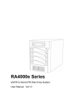
An optional handheld keypad (see Fig. 1.1) that allows access to the full
MM3000 command set without the use of a computer is available for either
front panel version.
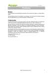
A possible motion system setup is shown in Fig. 1.1. In this configuration,
the MM3000 drives 4 stages and is controlled by a remote computer.
Digital I/Os could be used to trigger certain events and the remote “Motor
Off” switch allows the operator to disable any motion remotely.
To Other
Motion Controllers
Remote Motor
OFF
Digital/Analog
I/O's
Fig. 1.1—Controller setup
Section 1 — Introduction
1.7
To explore all capabilities of the MM3000 controller and identify the system
configuration that best fits your application, please read most of this
manual, or contact our experienced applications support group for advice.
1.3.1 Features
A number of advanced features make the MM3000 an excellent choice for
many applications:
• Integrated controller and driver design is cost effective and space
saving
• Compact, standard 3U height rack mountable or bench-top enclosure
(an optional fan unit adds 1U to the height of the MM3000)
• Allows any combination of motor types (stepper and DC) and sizes from
the supported list (Appendix C)
• Closed loop operation for stepper motors and DC motors
• Distributed processor architecture
• Real-time high speed command processing
• Over 100 powerful commands for most demanding applications
• Motion program storage (up to 99 programs) in 25 kB non-volatile
memory
• Advanced motion programming capabilities and complex digital and
analog I/O functions
• User selectable displacement units
• User settable compensation for linear errors and backlash
• Optional full-featured front panel with dedicated displays for each axis,
push-buttons for simple motion sequences and access to an elaborate
menu that allows setup of the system without use of a computer.
• Optional handheld keypad for full access to MM3000 command set
1.8
Section 1 — Introduction
1.3.2 Specifications
Function:
• Integrated motion controller and driver
Number of motion axes:
• 1 to 4, in any combination or order of stepper and DC motors
Trajectory type:
• Non-synchronized motion
• Multi-axis synchronized motion
• Trapezoidal velocity profile
Motion device compatibility:
• Family of motorized Newport motion devices, using either stepper or
DC motors
• Custom motion devices (call for compatibility)
DC motor control:
• 12 bit DAC resolution
• 1 MHz maximum encoder input frequency
• Digital PID servo loop
• 0.256 ms digital servo cycle
Stepper motor control:
• 1.5 MHz maximum pulse rate
• Full, half, ministep (fullstep/10) and microstep (full/100) capability
• Open or closed loop operation
Computer interfaces:
• RS-232C
• IEEE488
Utility interfaces
• 8 bit digital inputs/outputs, user definable
• Analog to digital converter, 8 channels, 10 bits each, 0–9V
• Optional digital to analog converter, 4 channels, 8 bits each, 0–9V
• Remote motor off input (interlock)
User Memory
• 25 KB non-volatile program memory
• 5 KB non-volatile macro memory
• 512 byte command buffer
Operating modes:
• Local mode – stand-alone operation, executing motion from the front
panel
• Remote mode – executing commands received over one of the
computer interfaces or the optional handheld keypad
• Program execution mode – execution of a stored program
Section 1 — Introduction
1.9
Optional display:
• 8 character alpha-numeric LED display for each axis
• Displays position, status, utility menus and setup screens
Dimensions:
• Without cooling fan: 5.28 (3U) H × 19 W × 16.50 D inches
(132 × 475 × 412 mm)
• With cooling fan: 5.94 (4U) H × 19 W × 16.50 D inches
(149 × 475 × 412 mm)
Power requirements:
• 115/230V ±10%, switchable, 50/60Hz
• 4A max.
Fuses
• AC line only
Line Voltage
115V/230V
Fuse Type
T4A/250V
Weight:
• 27 lb. max. (12 Kg max.)
Operating conditions:
• Temperature:
15°C to 40°C
• Humidity:
20% to 85% RH
• Rack Mounting Clearance: 0.5 in (top and bottom)
1.10
Section 1 — Introduction
1.3.3 Description of Front Panel
The MM3000 is available with either a blank front panel or a front panel
with dedicated displays for each axis. The front panel display version
includes one display for each axis (8 characters) and push-buttons for
simple manual motion sequences. Additionally, a menu allows the user to
set up the motion system without a computer interface.
Front Panel Display
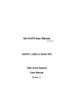
A general view of the front panel is shown in Fig. 1.2. There are three
distinct areas: a power section, a display section with 5 push-buttons for
each axis, and a menu section.
POWER SECTION
DISPLAY SECTION
MENU SECTION
Fig. 1.2—MM3000 front panel with displays
Blank Front Panel
This version does not provide any displays or local operation via menus. It
is equipped with the power section only. For description of the power
section refer to the following section.
Fig. 1.3—MM3000 blank front panel
Section 1 — Introduction
1.11
Description of Panel Sections
Power Section
POWER SECTION
The white push button type switch on the upper left corner is used to turn
the controller power on (I) or off (O). The blank front panel version
indicates the on state (I) with a green LED on the STOP ALL switch.
For safety reasons, the power to the motor can be controlled separately.
This is done from the front panel with the STOP ALL button. For easier
identification, the STOP ALL is the only one with a red push-button.
STOP
ALL
NOTE
Activating this switch aborts all motion and disables motor power. All
axes are affected.
The STOP ALL button has a red LED on the top that lights up momentarily
when this button is pushed.
The green LED underneath the button serves as an indicator for power
ON/OFF condition (blank front panel only).
An optional handheld keypad can be connected to the MM3000 through
this receptacle . Refer to Section 6.2 for a detailed description of the keypad.
KEYPAD
1.12
Section 1 — Introduction
Display Section
DISPLAY SECTION
Each of the four front panel displays is capable of displaying up to 8 alphanumeric characters. Display 1 refers to the Axis 1 connector on the back of
the controller, display 2 refers to Axis 2, and so on. The MM3000 alwayshas
4 displays no matter how many drivers are installed. Uninstalled drivers
result in a blank display for the respective axis.
Located underneath each display you will find 5 push-buttons whose
functions are described below.
Move in negative direction/jog.
To move a single step at a time, press this switch once.
To move continuously at low speed, press and hold the switch.
See Section 2 for setting of low speed rate.
The yellow LED above the switch indicates that the limit switch in the
negative direction has been activated.
Move in positive direction/jog.
To move a single step at a time, press this switch once.
To move continuously at low speed, press and hold the switch.
See Section 2 for setting of low speed rate.
The yellow LED above the switch indicates that the limit switch in the
positive direction has been activated.
While this button is pressed in combination with either jog button, the
motor moves with high speed. See Section 2 for setting of high speed rate.
HIGH SPEED
HOME
RESET
Section 1 — Introduction
Pressing the HOME switch will initiate a home search routine.
See Section 4 and OR command in Section 3 for a detailed description of
the home search cycle.
The yellow LED above the switch lights up when a home search is in progress.
Pressing the RESET push-button will perform the following:
1. Reset the position display readout to zero
2. Set the present position as the floating home point (see OR command in
the Command Section)
3. Set the present position as the reference for all subsequent absolute
positioning commands. See PA command in Section 3.
4. Shift the software limits setting such that the physical boundaries set
previously are retained. See SL command in Section 3.
1.13
Menu Section
MENU SECTION
The MM3000 features 4 push-buttons to operate a menu system used to set
parameters for each axis. Typical parameters that can be set are: type of
stage, velocity, acceleration, PID values for DC motors, etc.
The 4 pushbuttons have the following functionality:
Used to enter a menu and scroll through the menu selections.
See Section 2 for a deatiled description of the available menu items.
MENU/SELECT
While in menu mode, the LEDS above each switch light up if activating the
respective switch results in an action.
Used to select the displayed parameter or setting.
ENTER
Used to escape from the present menu level to the previous level above
without choosing the displayed parameter or setting.
ESCAPE
RUN/PAUSE
1.14
Pressed during execution of a program, program execution is terminated.
Used to Run a stored program. Pressed during execution of a running
program, the program is paused until this button is pushed again.
A flashing LED indicates that a program is paused.
Section 1 — Introduction
1.3.4 Rear Panel Description
NOTE
For pin-outs see Appendix B.
GPIO
JOYSTICK
RS-232C
AXIS CONNECTORS
IEEE488
MOTOR INTERLOCK
GROUND POST
Fig. 1.4—Rear panel of the MM3000
Axis Connectors (AXIS 1–AXIS 4)
There are four 25 pin D-Sub connectors on the rear panel, one for each axis.
An identification label that clearly specifies the model and the type of
motor that the respective axis is configured for can be found underneath
each connector. Unconfigured axes (i.e., there are no drivers installed) are
marked with labels that read “NO DRIVER”.
CAUTION
Read the labels below each axis connector carefully and make sure
that the specifications (motor type, voltage, current, etc.) match those
of the motion devices you intend to connect. Serious damage could
occur if a stage is connected to the wrong driver card.
GPIO Connector
This is a 37 pin D-Sub connector used for general purpose Input/Output
signals. A variety of commands are available to control of these ports. See
Section 3.
Joystick Connector
This 37 pin D-Sub connector is used to connect the optional joystick that
allows control of up to 4 axes. The pinout of this connector is equivalent to
the GPIO connector.
For a detailed description of the joystick see Section 6.1.
Motor Interlock Connector
The 9 pin D-Sub connector provides remote motor power interlock capability. One or more external switches can be wired to remotely inhibit the
motor power in a way similar to the STOP ALL button on the front panel.
Section 1 — Introduction
1.15
The controller is shipped with a mating 9 pin connector that provides the
necessary wiring to enable proper operation without an external switch.
RS-232C Connector
The RS-232C interface to a host computer or terminal is made through this
9 pin D-Sub connector. The port has a three-line configuration using a
software (XON/XOFF) handshake. The pinout enables the use of an off-theshelf, pin-to-pin cable by providing internal jumpers that bypass hardware
handshake signals, if needed.
IEEE488 Connector
This is a standard 24 pin connector to interface with a standard IEEE488
device.
Power Entry Module
The power entry section on the right side of the rear panel provides a
standard IEC 320 inlet, a fuse holder, a voltage selector and a binding post
to ground the controller if the main power supply wiring does not provide
earth ground terminals.
CAUTION
Make sure that the voltage shown at the voltage selector matchesthe
local line voltage before connecting the controller to power.
1.16
Section 1 — Introduction
1.4 System Setup
This Section guides the user through the proper set-up of the motion
control system.
If not already done, carefully unpack and visually inspect the controller and
stages for any damage.
Place all components on a flat and clean surface.
CAUTION
No cables should be connected to the controller at this point!
First, the controller must be configured properly before stages can be
connected.
1.4.1 Line Voltage Selection
CAUTION
Before applying AC power to the controller, check if the voltage
specified on the power entry module (Fig. 1.5) on the rear of the
controller corresponds to the local AC line voltage.
Fig. 1.5—Power Entry Section
If the indicated voltage as shown on the voltage selector does not match
the local line voltage, change the voltage as described below.
NOTE
The controller can operate with 115VAC, ±10% or 230VAC, ±10% ,
at a frequency of 50/60Hz.
Section 1 — Introduction
1.17
Changing the Line Voltage
1. If connected, remove the line cord from the power entry module.
2. Using a flat screwdriver, move the notch on the voltage selector as
shown in Fig. 1.6. so that it shows your local AC line voltage.
Fig. 1.6—Changing the Line Voltage
CAUTION
Make sure the main power switch on the front of the controller is
turned off (O) before connecting the controller to the AC line.
1.4.2 First Power ON
Plug the AC line cord supplied with the MM3000 into the power entry
module on the rear panel.
Plug the AC line cord into the AC wall-outlet.
Push in the POWER switch on the upper left side of the front panel .
Shortly after the power is switched on, the MM3000 with front panel
display will perform a start-up sequence as described below. The blank
front panel version indicates the ON state with a green LED below the STOP
ALL switch.
NOTE
Any time you call for technical support, the firmware version is
essential to trouble-shoot a problem. It is displayed every time the
controller power is turned on. Users of the blank front panel can
query the version with the VE command (see Section 3).
1.18
Section 1 — Introduction
— Momentarily display: “Newport” and the installed Firmware Version
— Momentarily show the type of motor to be connected: “DC SERVO” or
“STEPPER” for each axis that is configured. Displays for unconfigured
axes show “NO MODLE”.
— For any axis that is configured to drive a stage but no stage is connected, the following message is displayed.
Fig. 1.7—Display after initial power up, no stage connected
For axes that are configured and have a stage connected, a display as
shown below comes up.
Fig. 1.8—Display after power up with stage connected
CAUTION
The “NO STAGE” message should be displayed if the system is set up
the first time. If any of the displays shows “+0” (see Fig. 1.8), switch
off the unit and disconnect all stages that are connected to the controller before proceeding.
NOTE
If any other message than shown above is displayed or the display
does not light up at all, see Appendix for Troubleshooting Guide.
1.4.3 Verifying Default Devices
Before applying power to the motors, it is necessary to verify that the
controller is configured for the actual motion devices it is supposed to drive.
The following procedure provides a quick way to set up generic parameters
for each stage, e.g., PID parameters, velocities, accelerations. The values
entered with the TYPE menu ensure operation of the motion system
without having to “tune” the system. For optimal values for a specific
application, it is necessary to determine the proper PID parameters,
velocities, etc. using the procedure described in Section 4 and 5.
Section 1 — Introduction
1.19
1. Press the MENU/SELECT key → Axis 1 is displayed. Press MENU/
SELECT to move to the axis that you would like to check. Press ENTER
to pick the axis that you would like to check.
2. Press the MENU/SELECT key to move to the SEL TYPE menu. Press ENTER.
3. The displayed TYPE # should match the type for the motion device that
is connected to the respective axis. A cross reference between motion
devices and TYPE # can be found in Appendix C. In case there is a
mismatch, proceed as follows:
Press the MENU/SELECT key to select the TYPE # that the specific axis
is configured for. Press ENTER.
4. Press ESCAPE repeatedly to get back to the “NO STAGE” display.
NOTE
Users of the blank front panel need to verify the controller configuration
through one of the three interfaces (IEEE488, RS-232C or optional
keypad) before proceeding to connect stages. Please refer to the
appropriate Sections for instructions on the use of these interfaces.
NOTE
The TYPE# can also be set with the TY command. Refer to Section 3
for explanation of this command.
1.4.4 Connecting Motion Devices
If a standard motion control system was purchased, all necessary hardware
for set-up is included.
The configuration of each axis is identified with a label located underneath
each axis connector as shown:
MOTOR:
VOLT.:
CURR.:
UEXX
XXX VDC
XXA
CAUTION
Read the labels underneath each axis connector and make sure the
specifications (motor type, voltage, current) match those for the
motion devices you are connecting. Serious damage could occur if a
stage is connected to the wrong driver card.
Carefully connect one end of the supplied cables to the stage and the other
end to the appropriate axis connector on the rear of the controller. Secure
both connectors with the locking thumb-screws.
1.20
Section 1 — Introduction
1.5 Quick Start
This Section serves as a quick start for MM3000 with front panel display only.
Users of the MM3000 with blank front panel can skip to Section 3.
The following paragraphs guide you through a quick tour of the LOCAL
motion commands.
CAUTION
It is strongly recommended that you read at least the System Setup
Section before attempting to turn the controller or the motors on.
Serious damage could occur if the system is not properly configured.
1.5.1 Motor On
After the controller is properly configured and the stages connected as
described in the previous Section, the motors can be powered on.
Make sure that the motion devices are placed on a flat surface and their full
travel is not obstructed.
CAUTION
Be prepared to quickly turn the motor power off by pressing the STOP
ALL button or power switch if any abnormal operation is observed.
After the power switch is pushed in, the controller performs the start-up
sequence as described in Section 1.4.2. The default state after start-up is
motor power off. The display indicates disabled motor power with an
underline preceding any numbers (see below).
Fig. 1.9—Display showing motor off
To apply power to the motors, press either or once for the respective
axis. You may hear a small relay click inside the controller. The ON state
of the motor is indicated with the missing underbar, as shown below.
Fig. 1.10—Display showing motor on
Section 1 — Introduction
1.21
1.5.2 Homing Motion Devices
It is good practice to always home the motion device before executing any
motion. As described in detail in the Motion Control Tutorial Section,
homing a motion device means executing a special routine that locates a
predetermined position.
The MM3000 distinguishes between 3 different types of home:
1. The position defined by the location of a switch (mechanical, electrooptical, etc.) mounted on the stage.
2. The position defined by the location of a switch mounted on the stage
plus the occurrence of an index pulse after the switch is triggered.
3. The position that corresponds to a position count of 0.
Home position type 3 is referred to as a floating home because it can
always be defined by simply moving to a specific location and re-setting the
position number to 0 (see also DH command in Section 3).
Before initiating a HOME search, the MM3000 must be set for the type of
HOME search to be performed. The default type at initial power up is
floating home (type 3).
See OR command in Section 3 for instructions to change the type of home
search. Users of the display version can also use the menu (Section 2).
To initiate a home search, press the HOME key for the respective axis.
After the axis starts the homing cycle, all function keys will be disabled and
the display will indicate the progress. The LED above the HOME button
will light up as long as home search is in progress. After the selected axis
completes the search cycle, the LED is turned off.
1.5.3 First Jog
If is pressed, the selected axis will move slowly in the negative direction.
To move a single step at a time, press this switch once.
See Section 2 for setting of low speed rate.
If is pressed, the selected axis will move slowly in the positive direction.
To move a single step at a time, press this switch once.
See Section 2 for setting of low speed rate.
If the HIGH SPEED key between the jog keys or is pressed simultaneously
with one of the above keys, the axis will jog fast in the selected direction.
See Section 2 for setting of high speed rate.
At this point, you may experiment some more with the front panel to get
familiar with the controller and the local motion modes.
NOTE
Remember that only motions inside the software travel limits are
allowed (see SL command in Section 3). Any move outside these limits
will be ignored.
1.22
Section 1 — Introduction
Section 2
Modes of Operation
Contents
Section 2 — Modes of Operation
2.1 Overview of Operating Modes.................................................................. 2.3
LOCAL Mode .................................................................................................2.3
REMOTE Mode ..............................................................................................2.4
2.2 Menu Options in LOCAL Mode................................................................. 2.5
2.2.1 Accessing the Menu..........................................................................2.5
2.2.2 Detailed Description of Menu Items............................................... 2.7
Sel Prog.........................................................................................2.7
Set Vel ...........................................................................................2.7
Set Accl .........................................................................................2.8
Set PID ..........................................................................................2.9
Sel Home.....................................................................................2.10
Set Addr ......................................................................................2.11
Sel Optn ......................................................................................2.11
Sel Unit .......................................................................................2.14
Set Type......................................................................................2.16
Section 2 — Modes of Operation
2.1
2.2
Section 2 — Modes of Operation
Section 2
Modes of Operation
2.1
Overview of Operating Modes
The MM3000 can be operated in two modes:
— Local Mode
— Remote Mode
Following is an overview of these two modes of operation.
LOCAL Mode
This mode is applicable only if your unit is equipped with the optional front
panel display. If your MM3000 is equipped with the blank front panel, you
may skip to the REMOTE Mode Section.
In LOCAL mode, the user has access to a sub-set of MM3000 motion commands. In this mode, the MM3000 is controlled by pressing the keys on the
front panel. The displacement keys below each display allow manual
control of simple motion sequences and the menu keys on the right side of
the front panel provide access to a menu that enables the user to set up a
motion system without use of IEEE488 or RS-232C interfaces. The diagram
below illustrates the capabilities of the front panel display.
LOCAL MODE
MENU
SETUP
DISPLACEMENT
PROGRAM
EXECUTION
MANUAL MOTION
HOME Search
JOG LOW SPEED
JOG HIGH SPEED
SINGLE STEP
RESET DISPLAY
Fig. 2.1—LOCAL mode functions
Section 2 — Modes of Operation
2.3
MENU describes the 4 keys on the right side of the front panel. With these
keys, the user can setup the general operation of the controller and execute
programs that are stored in program memory.
DISPLACEMENT refers to simple manual motion using the 5 push-buttons
below each display. When the HOME button is pushed, the controller
executes a home search algorithm. The controller will exit this mode
automatically on task completion.
Please see Section 1.3.3 for a detailed description of the displacement keys.
REMOTE Mode
In REMOTE mode, the controller can be placed into two different sub-modes.
When placed in COMMAND mode, the MM3000 receives motion commands
through one of its interfaces (RS-232C or IEEE488) using a computer or
terminal. Additionally, an optional alphanumeric keypad with LCD display
enables the user to access the full command set of the MM3000 without the
use of a computer interface (see Section 6.2). The other sub-mode, called
PROGRAM EXECUTION mode, desribes a state in which the controller
executes up to 99 previously downloaded programs.
In either sub-mode, the MM3000 employs a set of over 100 commands. Please
refer to Section 3 for a detailed description of the MM3000 command set.
REMOTE MODE
FULL ACCESS TO MM3000 COMMAND SET
COMMAND MODE
PROGRAM EXECUTION MODE
Optional
IEEE-488
RS232-C
KEYPAD
Fig. 2.2—REMOTE mode structure
2.4
Section 2 — Modes of Operation
2.2
Menu Options in LOCAL Mode
This Section provides a comprehensive explanation of the menu items
available in LOCAL mode. Please remember that all menu items can also be
accessed with remote commands (see Section 3). Typical parameters that can
be set are: type of stage, velocity, acceleration, PID values for DC motors, etc.
2.2.1 Accessing the Menu
The menu can be accessed through the 4 menu keys on the right side of the
front panel as shown in Fig. 2.3.
MENU/SELECT
ENTER
ESCAPE
RUN/PAUSE
Fig. 2.3—Menu Keys
The 4 pushbuttons have the following functionality:
Used to enter a menu and scroll through the menu selections as shown in
Fig. 2.4.
MENU/SELECT
Used to accept the displayed parameter or menu item. Parameters are
stored in memory.
ENTER
Used to escape from the present menu level to the previous level without
choosing the displayed parameter or menu item.
ESCAPE
If the controller is executing a stored program, the ESCAPE button can be
used to quit program execution.
Used to run a stored program. Pressed during the execution of a program,
the program is paused until this button is pushed again.
RUN/PAUSE
A flashing yellow LED above the button indicates a paused program.
NOTE
All remote communication is ignored while the MM3000 is inthis mode.
Section 2 — Modes of Operation
2.5
Below you will find the menu structure.
AXIS-1
AXIS-2
AXIS-3
AXIS-4
SEL PROG
change parameter
SET VEL
JOG HIGH
JOG LOW
HOME HI
HOME LOW
SET VA
change parameter
SET ACCL
JOG ACCL
HOME ACL
SET AC
change parameter
SET PID
(DC MOTOR ONLY)
SET KP
SET KD
SET KI
SET IL
SET FE
change parameter
SEL HOME
FLOATING
SW+INDEX
SW ONLY
SET ADDR
change address
SEL OPTN
MOTR OFF
MOTOR ON
BEEP OFF
¥
¥
¥
REBOOT
SEL UNIT
RESOLUTN
UNIT
MILLIMTR
MICRON
INCH
MIL
DEGREE
MILLIDEG
MILLIRAD
MICRORAD
ENCODER
SEL TYPE
R-U-SURE
TYPE 1
TYPE 2
¥
¥
¥
TYPE n
0.049 µM
0.055 µM
0.074 µM
0.1 µM
0.5 µM
1.0 µM
2.54 µM
10.0 µM
0.001 DEG
0.005 DEG
0.010 DEG
Fig. 2.4—Menu-tree
2.6
Section 2 — Modes of Operation
2.2.2 Description of Menu Items
AXIS #
To enter the menu, press MENU/SELECT key. AXIS # will be displayed.
Repeatedly pressing the MENU/SELECT key advances to the desired axis.
Press ENTER to access the menu for the chosen axis.
(INTEGER) preceding a command - select axis
example: 1TP
/
tell position of axis 1
SEL PROG
This menu item allows the user to select a previously stored program for
execution. The chosen program will be executed when the RUN/PAUSE
button is pushed.
Programs can be downloaded to the MM3000 through its standard interfaces (IEEE488 or RS-232CC) or with the optional handheld keypad. The
MM3000 is capable of storing up to 99 different programs in its non-volatile
program memory (25KB total, see EP command in Section 3).
EX - execute program
SET VEL
This menu item makes it possible to change the velocities that are used in
connection with the jog and home search buttons. The following sub-menus
are available:
JOG HIGH
Sets the velocity of the stage when the HIGH SPEED button is pushed
simultaneously with c or b.
JH
- set jog high velocity
JOG LOW
Sets the velocity of the stage when either c or b is pushed continuously.
JW - set jog low velocity
Section 2 — Modes of Operation
2.7
HOME HI
Sets the high velocity on the initial motion towards the home location. See
Section 4.4.3 for details on the home search cycle.
OH
- set home high velocity
HOME LOW
Sets the low velocity for the final slow approach towards the home position.
See Section 4.4.3 for details on the home search cycle.
OL - set home low velocity
SET VA
Sets the maximum velocity for the optional joystick and velocities for other
move commands in remote mode unless otherwise specified with other
velocity commands.
VA - set absolute velocity
SET ACCL
This menu item enables the user to change accelerations that are used in
connection with c or b and home search.
The following sub-menus are available:
JOG ACCL
Sets the acceleration value used to accelerate (or decelerate) to the
desired velocity when the jog buttons are used.
See Section 4.4.1 for details on the velocity profile.
JA
- set jog acceleration
HOME ACL
Sets the acceleration (and deceleration) value for the home search cycle.
See Section 4.4.3 for details on homing.
OA
2.8
- set home search acceleration
Section 2 — Modes of Operation
SET AC
Sets the acceleration (or deceleration) for joystick operation and other
move commands in remote mode unless the acceleration is specified in
remote mode.
SET PID
This menu allows the user to modify the digital PID filter for DC motors. All
standard motion devices offered with the MM3000 have a set of conservative
PID parameters stored in the controller’s firmware. To change them, some
knowledge of motion control loops is needed. Therefore, it is not recommended to modify the pre-set values before reading some general guidelines
in the Servo Tuning Section. See also Section 4 for details on PID servo loops.
The recommended set of PID parameters for a specific stage can be found
in Appendix C. They can also be programmed with the help of the SEL TYPE
menu, which is the recommended method for first time users.
The following sub-menus are available:
SET KP
This parameter is the proportional gain factor of the digital PID filter.
KP
- set proportional gain
SET KD
This parameter is the derivative gain factor of the digital PID filter.
KD
- set derivative gain
SET KI
This parameter is the integral gain factor of the digital PID filter.
KI
- set integral gain
SET IL
This parameter is the limit for the integrated value due to the integral gain
factor of the digital PID filter multiplied with the following error.
IL
Section 2 — Modes of Operation
- set integral gain
2.9
SET FE
This parameter represents the maximum following error, i.e., the difference
between commanded and actual position. If at any time, the following error
for a specific axis exceeds this value, the controller stops motion in
progress and turns motor power off. Use good judgment when setting this
parameter. A small value will cause premature fault and a large value will
not protect the system from a real problem.
FE
- set maximum following error
SEL HOME
This menu allows the user to choose between 3 different type of homing.
Please refer to Section 1.5.2 for a description of the home search types.
This menu only selects the type of homing, but does not initiate a home
search. After the type selection has been made, exit the menu and push the
HOME button for the respective axis or send the OR command.
The following sub-menus are available:
FLOATING
Floating home search means the controller returns the stage to 0 position
count.
OM0
- Origin mode 0 (home 0)
SW+INDEX
SW+INDEX home search means the controller returns the stage to a position determined by a home switch in connection with an index pulse.
OM1
- Origin mode 1 (home 1)
SW ONLY
SW ONLY home search means the controller returns the stage to a position
determined by a home switch only. No index pulse is required.
If this mode is chosen for DC motors, a jumper has to be set inside the
controller. Refer to the Appendix I for instructions.
OM2
2.10
- Origin mode 2 (home2)
Section 2 — Modes of Operation
SET ADR
Sets the address for IEEE488 and RS-232C daisy chain mode (see Appendix E).
The setting will be stored in non-volatile memory.
AD
- set address
SEL OPTN
This provides access to a set of sub-menus that allow the user to change
numerous options, e.g., motor power, beep on/off, etc. Some of the items
available depend whether the axis is a DC or stepper.
MOTR OFF
MOTR OFF removes power from the motor for the respective axis. To
quickly turn motor power off to all axes, press the STOP ALL button.
MF
- motor off (axis 1)
MOTOR ON
MOTOR ON applies power to the motor. Note that any move command
automatically applies power to the motor.
MO
- motor on (axis 1)
BEEP OFF
The MM3000 provides acoustic feed-back for the push-buttons and certain
occurences. With this menu item, the beeper can be disabled.
FS 40
- disable beep
BEEP ON
The MM3000 provides acoustic feed-back for the push-buttons and certain
occurences. With this menu item, the beeper can be enabled.
FS&BF
Section 2 — Modes of Operation
- enable beep
2.11
JOYSTK#
JOYSTK# assigns a specific controller axis to a joystick axis. Refer to
Section 6.1 for details.
1JY1
- assign joystick axis 1 to controller axis 1
LOOP ON
This item is available for stepper axes only. LOOP ON enables closed loop
operation of stepper motors (see CL command for details).
CL ON
- closed loop on (axis 1)
LOOP OFF
This item is available for stepper axes only. LOOP OFF disables closed loop
operation of stepper motors.
CL OFF
- closed loop off (axis 1)
BASE 100
This item is available for stepper axes only. BASE 100 sets the start and
stop speed of stepper motors to 100 steps/sec (see VB command).
VB
- set base velocity
BASE 4000
This item is available for stepper axes only. BASE 4000 sets the start and
stop speed of stepper motors to 4000 steps/sec (see VB command).
VB
- set base velocity
RATIO 1
This item is available for stepper axes only. RATIO 1 sets the encoder/pulse
ratio to 1. See ER command for details.
ER
2.12
- set encoder ratio
Section 2 — Modes of Operation
RATIO 10
This item is available for stepper axes only. RATIO 10 sets the encoder/pulse
ratio to 10. See ER command for details.
ER
- set encoder ratio
STEP CNT
This item is available for stepper axes only. STEP CNT places the axis in
step count mode. All positioning and position reporting is in step counts.
See FM command for details.
FM
- format motion
ENCR CNT
This item is available for stepper axes only. ENCR CNT places the axis in
encoder count mode. All positioning and position reporting is in encoder
counts. See FM command for details.
FM
- format motion
SRQ ON
SRQ ON enables SRQ for IEEE488 interface.
FI
- format interrupt
SRQ OFF
SRQ OFF disables SRQ for IEEE488 interface.
FI 00
- format interrupt (SRQ OFF)
SOFT ON
This menu enables the soft travel limits. See SL command for details.
FM
Section 2 — Modes of Operation
- format motion
2.13
SOFT OFF
This menu disables the soft travel limits. See SL command for details.
FM
- format motion
DAISY ON
This menu enables daisy chain mode for the RS-232C interface.
See Appendix E for details.
DC 1
- Daisy chain mode on
DAISY OFF
This menu disables daisy chain mode for the RS-232C interface.
See Appendix E for details.
DC 0
- Daisy chain mode off
REBOOT
This menu reboots the controller. Any commands in the command buffer
are erased at this point. Rebooting is equivalent to a power on/off cycle of
the controller.
RS
- reboot controller
PURGE MEM
This menu erases the contents of the non-volatile memory. See XX command for details. Use this menu only in case the memory gets corrupted
and causes faulty operation.
SEL UNIT
The MM3000 is capable of displaying position in different measurement
units (e.g., microns). The type of units to be displayed is indicated on the
right side of the 8 digit LED field.
Additionally, a number of commands support positioning in units. See UA,
UV, UR, UP, US, UU and UW commands for details.
It is necessary to first determine the stage resolution before a measurement
unit can be chosen. See US command for details.
2.14
Section 2 — Modes of Operation
RESOLUTN
This menu allows the user to select a range of predefined encoder resolutions
for a specific stage.
US
- unit resolution
UNIT
After the resolution of the stage has been entered with the RESOLUTN menu,
the user can choose between selected measurement units for either rotary
or linear motion.
The selecton is as follows:
MILLIMTR
Millimeter (10–3 m)
MICRON
Micrometer (10–6 m).
INCH
Inch
MIL
Milli-inch (10–3 inch)
DEG
Degree
MILLIDEG
Milli-degree (10–3 degree)
MILLIRAD
Milli-radiant (10–3 radiant)
MICRORAD
Micro-radiant (10–6 radiant)
ENCODER
Encoder counts
UU
Section 2 — Modes of Operation
- units
2.15
SEL TYPE
This menu item allows the user to configure the MM3000 with all necessary
parameters (e.g., PID, velocities, accelerations, etc., see TY command in
Section 3) without individually entering each value. All parameters are
generic. For optimal parameters it is necessary to “tune” the system for a
specific application (see Sections 4 and 5). For a cross reference between
TYPE# and motion devices, see Appendix C.
2.16
Section 2 — Modes of Operation
Section 3
Remote Mode
Contents
Section 3 — Remote Mode
3.1 Programming Modes..................................................................................3.3
Command Mode ..........................................................................3.3
Program Execution Mode........................................................... 3.4
Summary ......................................................................................3.5
3.2 Remote Interfaces ......................................................................................3.6
3.2.1 RS-232C Interface .............................................................................3.6
Hardware Configuration............................................................. 3.6
Communication Protocol ........................................................... 3.6
Daisy-Chaining Multiple MM3000’s........................................... 3.6
3.2.2 IEEE488 Interface .............................................................................3.7
Hardware Configuration............................................................. 3.7
Communication Protocol ........................................................... 3.7
Use of SRQ Line ...........................................................................3.8
Serial Poll .....................................................................................3.8
3.3 Software Utilities ........................................................................................3.9
Start-Up Program ..........................................................................................3.9
Profile .............................................................................................................3.9
EZ232 .............................................................................................................3.9
3.4 Command Syntax .....................................................................................3.10
3.4.1 Summary of Command Syntax ...................................................... 3.11
Command Format .....................................................................3.11
Blank Spaces ..............................................................................3.11
Command Line...........................................................................3.11
Separator ....................................................................................3.11
Terminator .................................................................................3.11
3.5 Command Summary.................................................................................3.12
3.5.1 Command List by Category ........................................................... 3.12
3.5.2 Command List - Alphabetical ........................................................ 3.14
3.6 Description of Commands ......................................................................3.16
Section 3 — Remote Mode
3.1
3.2
Section 3 — Remote Mode
Section 3
Remote Mode
3.1 Programming Modes
The MM3000 is a command driven system. Commands are a series of two
letter ASCII characters with a numeric parameter denoting the axis number
to be addressed. To communicate with the MM3000, a host terminal has to
transfer ASCII character commands according to the respective communication protocol (see Section 3.2 for IEEE or RS232 interfaces).
As briefly mentioned in Section 2, the MM3000 distinguishes between two
different programming modes:
Command Mode
In this mode, the MM3000 provides a 512-byte command input buffer
enabling the host terminal (e.g, PC) to download a series of commands and
then proceed to other tasks while the MM3000 processes the commands.
As command characters arrive from the host terminal, they are placed into
the command buffer. When a carriage-return (ASCII 13 decimal) terminator
is received, the command is interpreted. If the command is valid and its
parameter is within the specified range, it will be executed. If the command
contains an error, it will not be executed and a corresponding error message will be stored in the output buffer.
NOTE
The MM3000 power up state is command mode.
An example of a typical command sequence is shown below:
Example 1:
1PA+3000
| move axis 1 to absolute position 3000
1WS
| wait for axis 1 to stop
2PR-1000
| move axis 2 to relative position 1000
Assuming that axis 1 and 2 are configured, example 1 instructs the MM3000
to move axis 1 to absolute position +3000, wait for it to stop, and then
move axis 2 motor to –1000 counts relative to its previous position.
Note that a command prefix (1 through 4) identifies the axis that should
execute a command. Commands received without an axis prefix default to
the last prefix (axis) issued. If a command is referenced to a non-existing
axis, an error is generated. See Section 3.4 for further datails on the command syntax.
Section 3 — Remote Mode
3.3
Also note the necessity to explicitly instruct the MM3000 with theWS (Wait
for Stop) command to wait for axis 1 motion to stop. This is necessary
because the MM3000 executes commands contiguously as long as there are
commands in the buffer unless a command is fetched from the buffer that
instructs to wait. Executing a move does not automatically suspend command
execution until the move is complete. If the WS command were not issued
in example 1, the controller would start the second move immediately after
the first move begins and simultaneously move axis 1 and axis 2.
NOTE
Unless instructed otherwise, the MM3000 executes commands in the
order received without waiting for completion of previous commands.
Remember, commands must be terminated with a carriage-return (ASCII 13
decimal). Until a terminator is received, characters are simply kept in
contiguous buffer space without evaluation.
Example 2:
1PA+3000;1WS;2PR-1000
Example #1 and #2 perform the same operations. In example #2 however,
semicolons are used in place of carriage-returns as command delimiters,
keeping the MM3000 from interpreting any commands on that line until the
carriage-return terminator is received at the very end of the string.
Program Execution Mode
The MM3000 also implements an internal program execution mode that
enables the user to store up to 99 programs in a 25 kB non-volatile memory.
Additionally, 5kB of memory can be dedicated to program macros (see CM
command).
Even while executing stored programs, the MM3000 maintains open communication channels so that the host terminal can continue to direct the MM3000
to report any desired status, and even execute other motion commands.
Let’s illustrate program execution mode using the previous example:
Example 3:
EP
| invoke program entry mode
1PA+3000
| enter program
1WS
2PR-1000
%
| exit program entry mode
CP
| compile stored program
COMPILATION COMPLETED
| response from MM3000
END
| response from MM3000
EX1
| execute compiled program # 1
As shown above, the sequence of commands has to be downloaded into the
MM3000 program memory without inadvertently executing them. To facilitate this, the system provides the EP (Enter Program) command; characters
received thereafter are redirected to program memory. Commandsyntax and
parameters are not evaluated (even after the carriage-return). Instead, they
are treated as a series of characters to be stored in contiguous memory.
3.4
Section 3 — Remote Mode
/QP separates multiple programs. Program numbers are incremented by 1
with every /QP issued. Up to 99 programs can be created this way and
executed independently.
The MM3000 continues to store commands in memory until it receives the
% character followed by a carriage return, which instructs to exit program
entry mode and return to command mode.
The CP command causes the MM3000 to evaluate the stored programs
(source code) for incorrect syntax and parameters usage. If the downloaded
commands contain errors, the compiler responds with the error message
“COMPILATION ABORTED” plus the listing of all the lines which contained
an error. The last transmission is the word END to signal the end of data.
Assuming there are no errors, the execute program command (i.e.,EX) can
be issued to execute programs. If the program has not been compiled prior
to issuing the EX command, EX will automatically compile and execute if
no errors exist. Note, while the program is running, certain commands can
still be transmitted and executed, e.g., 2TP (tell position), 1VA5000 (absolute
velocity), or 3PR1000 (position relative).
Summary
Command Mode
1. Commands are received and temporarily stored in a 512 byte command
queue until they are fetched and executed.
2. A carriage-return (ASCII 13 decimal) terminates a command and causes
the MM3000 to begin processing.
3. Multiple commands (up to 80 characters) may exist on a single line if
delimited by semicolons, e.g., 1PR+1000;1WS;2PR-1000;2WS
4. Commands missing axis prefixes default to the last reference, e.g.,
1PA+1000;WS (the WS command defaults to axis 1)
5. The WS or WA command causes the MM3000 to wait until the target
position is reached before processing the next command.
Program Execution Mode
1. The EP command invokes program entry mode which transfers incoming characters to program memory.
2. /QP starts a new program (old program number + 1)
3. The % command causes the system to exit program entry mode.
4. A stored program must be successfully compiled with the CP command
before it can be executed. Alternatively, the EX command compiles and
executes programs if no errors exist.
5. New real-time commands are accepted and executed even while running
a program.
6. The WS or WA command causes the MM3000 to wait until the target
position is reached before processing the next command.
Section 3 — Remote Mode
3.5
3.2 Remote Interfaces
In this manual, Remote Interface refers to the two communication interfaces
that the controller can use to communicate with a computer or a terminal
via commands in ASCII format. It is not called a Computer Interface since
any device capable of sending ASCII characters can be interfaced with the
controller.
The Remote Interface should not be confused with the General Purpose
Input/Output (analog and digital I/Os, a.k.a. GPIO).
3.2.1 RS-232C Interface
Hardware Configuration
The serial (RS-232C) communication interface on the MM3000 is accessed
through the 9 pin Sub-D connector located on the rear panel. The pinout is
designed to interface directly with an IBM PC or compatible computer,
using a straight through cable.
Appendix B shows the pinout of the RS-232C connector and different cable
types that may be used to interface to a computer.
Communication Protocol
The RS-232C interface must be properly configured on both devices communicating. A correct setting is one that matches all parameters (baud
rate, number of data bits, number of stop bits, parity type and handshake
type) for both devices.
The MM3000 RS-232C configuration is fixed at 8 data bits, no parity, and
1 stop bit.
The baud rate can be set with the SR command (see Command Section).
To prevent buffer overflow when data is transfered to the MM3000 input
buffer (512 Byte), an XON/XOFF protocol is implemented. The host terminal can control transmission of characters from the MM3000 by sending
XON/XOFF control commands. Before sending any further characters, the
MM3000 will wait for an XON (ASCII 17 decimal) if the host terminal previously sent an XOFF (ASCII 19 decimal) to stop transmission. If no XON is
received within 0.5 seconds, the MM3000 will time-out.
As soon as its 512 byte command buffer is full, the MM3000 sends an XOFF.
Then, as space becomes available as the MM3000 reads and executes
commands in its buffer, it will send an XON to the host terminal.
See FO command to enable or disable XON/XOFF handshaking.
Daisy-Chaining Multiple MM3000’s
The MM3000 provides support for daisy-chained RS-232C serial communication. Up to 32 MM3000’s may be controlled through one single RS-232C
host serial port. Without this feature, every MM3000 would require a
separate serial port.
3.6
Section 3 — Remote Mode
When an MM3000 receives a character from the host terminal in daisychained RS-232C mode, it always sends that character to the next MM3000
in the chain. At the end of the chain, the last MM3000 will send the command
back to the host computer. Each string sent to the host terminal by the
MM3000 has an axis prefix number followed by a “>”.
NOTE
To guarantee only one “talker” in the chain at a time, responses from
each MM3000 should be synchronized by disabling RS-232C error
message transmission using the FO command.
For a more detailed explanation of the FO command see Section 3.6.
Please refer to Appendix E for details on the daisy chain mode.
3.2.2 IEEE488 Interface
Hardware Configuration
A typical IEEE488 setup consists of a controller (host terminal) and several
devices connected to the bus. All devices are connected in parallel to the
data lines, data management and sychronization lines. As a result of this
type of connection, each device on the bus must have an address so that
the controller can selectively communicate with it.
The address can be set through the optional front panel display or with the
AD command. Alternatively, the required address can be set using DIP
switches inside the MM3000. See Appendix F for instructions. Whichever
address set last overrides the previous address and is stored in non-volatile
memory. It remains valid during all subsequent power on/off cycles.
See Section 2.2 for setting the address using the front panel menu.
Communication Protocol
The IEEE488 interface is implemented on the MM3000 somewhat differently
from a typical instrument because the standard IEEE488.2 command set
and command format are inadequate for a complex motion controller.
Since the MM3000 has its own language and command set, the IEEE488
interface is used only as a communication port. The extended protocol is not
supported.
The MM3000 has an ASCII command set and also outputs system status in
ASCII format. It features a 512 byte command input buffer. If the buffer fills
up, the MM 3000 will not allow further communication until space becomes
available to accept new characters.
To send a command to the MM3000, use the command specifc to your
IEEE488 terminal (e.g., output(ASCII)).
If the host terminal asks the MM3000 for a response (e.g., input(ASCII)) and
no response is obtained within 0.5s, the MM3000 will time-out. Time-out
can be disabled with the FO command (see Command Section).
Section 3 — Remote Mode
3.7
Use of SRQ Line
The MM3000 can be programmed to generate an IEEE488 service request
on occurrence of certain events. These events are:
• Motion complete on any of the 4 axes, or Command errors and messages.
The FI command can be used to select the event that should cause this
type of service request. See Command Section for further information.
• Execution of an RQ command
Sometimes, it may be more efficient and possibly desirable to generate a
service request when a sequence of commands is completed, rather
than when each individual motion is finished. The RQ command can be
used for this task. Here, a service request is generated only when an
RQ command is executed. To use the RQ command for service request
generation, FI interrupts have to be disabled (see FI command in
Section 3.6).
The following example illustrates the use of the RQ command:
1PR100;WS;2PR100;3PR100;WS;RQ
In the above example, the SRQ line is asserted only after execution of
the sequence preceding the RQ command is finished.
Serial Poll
When the IEEE488 controller senses a service request on the bus, it creates
an interrupt to the application program. The application program must
contain a service routine for this interrupt. First, the program must determine which device on the bus generated the service request. This is usually
achieved with a function called serial poll. The exact syntax for the serial
poll command depends on the IEEE488 controller.
Using that interrupt service routine, a serial poll command can be issued to
each device (e.g., MM3000). The device polled at each instance will respond
with a status byte. Bit 6 of the status byte indicates whether a specific device
generated the service request. Bits 0 through bit 5 contain additional
system status information which indicate the reason why the service
request was generated.
Please refer to TS command for a description of the status byte.
3.8
Section 3 — Remote Mode
3.3 Software Utilities
In order to communicate with the controller, the user must have a terminal
or a computer capable of communicating through RS-232C or IEEE488. One
approach is to use a computer with communications software that can
emulate a terminal. An even easier solution is to use one of the software
utilities included with the controller.
The MM3000 is supplied with three utility software programs. These
programs are designed to work on a DOS based computer. Their main
purpose is to help the user setup the motion control system, exercise
controller capabilities and to calibrate and tune the system for best performance.
Though any type of motion program can be created using these utilities,
many users will prefer to use their own environment that better fits their
application.
A complete description of the programs and their features can be found in
the EZ Motion Control Utilities User Manual.
Start-Up Program
This is an intelligent terminal emulator that was written specifically for the
MM3000. The software works very closely with the controller. It knows the
language and the conventions of the controller. It knows what to ask and what
to expect back. It is an extension of the controller, a motion control environment. The status of the controller and the motion devices can be continuously
monitored. Complex programs can be created, tested, saved and recalled.
Profile
Its purpose is to facilitate tuning of the PID servo loops easily and intuitively. It automatically controls the MM3000, reads and calculates all
important dynamic motion parameters and plots graphically. This utility is
designed to be used primarily by more experienced users, with some
knowledge of servo systems. There is always some risk involved in changing the servo loop parameters in a manner that could render the motion
device inoperative, or even damage it. Before using this program, read the
Servo Tuning and, if needed, the Motion Control Tutorial chapter.
EZ232
This is a general purpose RS232-C serial interface communications program.
This utility will allow users that are already familiar with the MM3000
command syntax to send commands and read responses from the controller.
Section 3 — Remote Mode
3.9
3.4 Command Syntax
As mentioned previously, the MM3000 utilizes an ASCII command set and
also outputs system status in ASCII format.
MM3000 commands consist of an axis designator followed by two letter
mnemonic characters, (mostly) followed by a numerical parameter and
terminated by a carriage return. Commands may be either upper or lower
case characters and with or without spaces anywhere in the command line.
For example, 3Pa +100 is a valid command. A command sent without an
axis number defaults to the last axis addressed. In the command sequence
2PA+100;WS10;TP, the WS and TP commands default to axis 2.
The diagram below illustrates the command syntax.
axis address
command
parameter
terminator
(carriage return)
command
seperator
(;)
NOTE
An MM3000 command (or a sequence of commands) has to be terminated
with a carriage return character. However, responses from the MM3000
are always terminated by a carriage return/line feed combination.
This setting may not be changed. If the IEEE interface is used, the
IEEE controller has to be configured to terminate the input (read)
function when it senses the line feed character.
3.10
Section 3 — Remote Mode
Summary of Command Syntax
Command Format
xx AA nn
The general format of a command is a two character mnemonic (AA). Both
upper and lower case are accepted. Depending on the command, it could
also have optional or required preceding (xx) and/or following (nn) parameters.
Blank Spaces
Blank spaces are allowed and ignored in any position, including inside a
numerical value. For the clarity of the program and memory saving considerations, use blank spaces with restraint. The following two commands are
equivalent
2P A1 00
0
2PA1000
but the first example is very confusing and uses more than twice the
memory
Command Line
Commands are executed line by line. A line can consist of one or a number
of commands. The controller will interpret the commands in the order they
are received and execute them sequentially. This means that commands
issued on the same line are executed significantly closer to each other than
if they would be issued on separate lines. The maximum number of characters allowed on a command line is 80.
Separator
Commands issued on the same line must be separated by semicolons (;).
Terminator
Each command line must end with a line terminator, i.e., carriage return.
Section 3 — Remote Mode
3.11
3.5 Command Summary
The MM3000 controller understands more than 100 commands. The
following two tables list all of them, sorted first by category and then
alphabetically. The tables also show the operating modes in which each
command can be used. The acronyms used in the tables have the following
meaning:
IMM
IMMediate mode
controller is idle and the commands will be
executed immediately.
PGM
ProGraM mode
controller does not execute but stores all
commands as part of a program. EP activates
this mode and % exits it.
MIP
Motion In Progress controller executes a motion on the specified axis.
3.5.1 Command List by Category
Cmd.
Motion
AB
AC
JA
JH
JW
ML
MV
MZ
OA
OH
OL
OR
PA
PR
SD
ST
VA
VB
VR
VS
Description
Abort motion
Set acceleration
Set jog acceleration
Set jog high speed
Set jog low speed
Move to travel limit
Move indefinitely
Move to index pulse
Set origin search acceleration
Set origin search high velocity
Set origin search low velocity
Perform origin search
Position absolute
Position relative
Speed divide
Stop motion
Set velocity value
Set base velocity: start/stop velocity
Increment/decrement present velocity
Sample-time velocity mode
Motion in Units
UA
Set unit acceleration
UP
Move to absolute unit position
UR
Units position relative
US
Define resolution
UU
Select positioning unit
UV
Set unit velocity
3.12
IMM PGM MIP
Page
䊏
䊏
䊏
䊏
䊏
䊏
䊏
䊏
䊏
䊏
䊏
䊏
䊏
䊏
䊏
䊏
䊏
䊏
䊏
䊏
䊏
䊏
䊏
䊏
䊏
䊏
䊏
䊏
䊏
䊏
䊏
䊏
䊏
䊏
䊏
䊏
䊏
䊏
䊏
䊏
䊏
䊐
䊏
䊏
䊏
䊏
䊏
䊏
䊏
䊏
䊏
䊐
䊏
䊏
䊏
䊏
䊏
䊏
䊏
䊏
3.17
3.18
3.52
3.53
3.55
3.63
3.66
3.67
3.68
3.69
3.70
3.72
3.74
3.77
3.89
3.93
3.121
3.122
3.124
3.125
䊏
䊏
䊏
䊏
䊏
䊏
䊏
䊏
䊏
䊏
䊏
䊏
䊐
䊏
䊏
䊐
䊐
䊏
3.110
3.113
3.115
3.117
3.118
3.119
Section 3 — Remote Mode
Cmd.
Section 3 — Remote Mode
Description
IMM PGM MIP
Page
Motion Related
BA
Enable backlash compensation
CL
Enable closed loop stepper
CO
Enable linear compensation
DH
Define home
DS
Derivative sampling interval
FE
Set following error threshold
IL
Set integration limit
JY
Enable joystick control
KD
Set PID Derivative constant
KI
Set PID Integration constant
KP
Set PID Proportional constant
MF
Turn motor power off
MO
Turn motor power on
OV
Set overshoot value for home search
SE
Simultaneous command execution
SL
Set soft (travel) limits
SY
Set axes for simultaneous execution
TY
Select stage type
UF
Update PID filters
䊏
䊏
䊏
䊏
䊏
䊏
䊏
䊏
䊏
䊏
䊏
䊏
䊏
䊏
䊏
䊏
䊏
䊏
䊏
䊏
䊏
䊏
䊏
䊏
䊏
䊏
䊏
䊏
䊏
䊏
䊏
䊏
䊏
䊏
䊏
䊏
䊏
䊏
䊐
䊐
䊐
䊏
䊏
䊏
䊏
䊏
䊏
䊏
䊏
䊏
䊏
䊏
䊏
䊏
䊏
䊐
䊏
3.20
3.24
3.27
3.31
3.34
3.40
3.51
3.56
3.57
3.58
3.59
3.62
3.64
3.73
3.90
3.91
3.95
3.109
3.112
Programming
CM
Create macro
CP
Compile program
EM
Execute macro
EP
Enter program mode
EX
Execute program
IE
Initialize time interval execution mode
LM
List all macro definitions
LP
List stored program
PE
Power-on execution
QP
Quit program execution mode
/QP
Program delimiter
RM
Reset all macro definitions
RQ
Generate interrupt
SV
Set variable value
%
Quit program entry mode
‘
Program line comments
䊏
䊏
䊏
䊏
䊏
䊏
䊏
䊏
䊏
䊏
䊐
䊏
䊏
䊏
䊏
䊐
䊐
䊐
䊏
䊐
䊐
䊏
䊏
䊐
䊐
䊐
䊏
䊏
䊏
䊏
䊐
䊏
䊏
䊐
䊐
䊐
䊐
䊏
䊏
䊏
䊐
䊐
䊐
䊏
䊏
䊏
䊐
䊐
3.26
3.28
3.36
3.37
3.39
3.49
3.60
3.61
3.76
3.79
3.80
3.84
3.86
3.94
3.134
3.135
Reporting
DA
DP
DV
MS
RA
RB
RC
TB
TE
TF
TL
TM
TP
TPE
TPI
TR
TS
TT
TV
VE
䊏
䊏
䊏
䊏
䊏
䊏
䊏
䊏
䊏
䊏
䊏
䊏
䊏
䊏
䊏
䊏
䊏
䊏
䊏
䊏
䊏
䊏
䊏
䊏
䊏
䊏
䊏
䊏
䊏
䊏
䊏
䊏
䊏
䊏
䊏
䊏
䊏
䊏
䊏
䊏
䊏
䊏
䊏
䊏
䊏
䊏
䊏
䊏
䊐
䊏
䊏
䊏
䊏
䊏
䊏
䊏
䊏
䊐
䊏
䊏
3.29
3.33
3.35
3.65
3.81
3.82
3.83
3.96
3.97
3.98
3.100
3.101
3.102
3.103
3.104
3.105
3.106
3.107
3.108
3.123
Tell desired acceleration
Tell desired position
Tell desired velocity
Tell motor status
Read analog channel
Read I/O bits
Report module configuration
Tell error buffer contents
Tell error code
Tell filters (PID)
Tell soft limits and following error
Tell memory usage
Tell actual position
Tell positon in encoder units
Tell position in motor step units
Initialize motion tracing mode
Tell status
Tell motion trace data
Tell velocity
Tell firmware version
3.13
Cmd.
Description
Sequence
DL
Define label
IF/THEN
IF condition THEN goto label
JL
Jump to label
RP
Repeat previous command
UW
Wait for position crossing in units
WA
Wait for all axes to stop
WB
Wait bit level, then execute
WHILE/WEND
WHILE bit(s) high/low ...WEND
WP
Wait for position, then execute
WS
Wait for stop, then execute
WT
Wait time, then execute next command
Miscellaneous
AD
Set address
BI
Define input bits
BO
Define output bits
CB
Clear bits
DC
Enable/disable daisy-chaining
ER
Set encoder ratio
FI
Format interrupt
FM
Format motion
FO
Format output
FS
Format system
OM
Set home search type
RS
Reboot system
SB
Set bits high
SR
Select baud rate
TG
Toggle bits
WD
Write value to D/A channel
XX
Purge memory
#
Emergency stop
3.5.2
Cmd.
AB
AC
AD
BA
BI
BO
CB
CL
CM
CO
CP
DA
DC
DH
DL
DP
DS
DV
EM
EP
ER
3.14
IMM PGM MIP
Page
䊐
䊐
䊐
䊏
䊏
䊏
䊏
䊏
䊏
䊏
䊏
䊏
䊏
䊏
䊐
䊏
䊏
䊏
䊐
䊏
䊏
3.32
3.50
3.54
3.85
3.120
3.126
3.127
䊏
䊏
䊏
䊏
䊏
䊏
䊏
䊏
䊏
䊏
䊏
䊏
3.129
3.130
3.131
3.132
䊏
䊏
䊏
䊏
䊏
䊏
䊏
䊏
䊏
䊏
䊏
䊏
䊏
䊏
䊏
䊏
䊏
䊏
䊏
䊏
䊏
䊏
䊏
䊏
䊏
䊏
䊏
䊏
䊏
䊏
䊏
䊏
䊏
䊏
䊐
䊐
䊏
䊏
䊏
䊏
䊏
䊐
䊏
䊏
䊏
䊏
䊏
䊏
䊏
䊏
䊏
䊏
䊐
䊏
3.19
3.21
3.22
3.23
3.30
3.38
3.41
3.43
3.45
3.47
3.71
3.87
3.88
3.92
3.99
3.128
3.133
3.136
Command List - Alphabetical
Description
Abort motion
Set acceleration
Set address
Enable backlash compensation
Define input bits
Define output bits
Clear bits
Enable closed loop stepper
Create macro
Enable linear compensation
Compile program
Tell desired acceleration
Enable/Disable daisy-chaining
Define home
Define label
Tell desired position
Derivative sampling interval
Tell desired velocity
Execute macro
Enter program mode
Set encoder ratio
IMM PGM MIP
䊏
䊏
䊏
䊏
䊏
䊐
䊏
䊏
䊏
䊏
䊏
䊐
䊏
䊏
䊏
䊏
䊏
䊏
䊏
䊏
䊏
䊏
䊏
䊐
䊏
䊐
䊏
䊏
䊏
䊐
䊏
䊐
䊐
䊏
䊏
䊏
䊏
䊏
䊏
䊏
䊏
䊏
䊐
䊏
䊐
䊏
䊏
䊏
䊏
䊏
䊏
䊏
䊏
䊏
䊏
䊏
䊐
䊏
䊐
䊐
䊏
䊏
䊐
Page
3.17
3.18
3.19
3.20
3.21
3.22
3.23
3.24
3.26
3.27
3.28
3.29
3.30
3.31
3.32
3.33
3.34
3.35
3.36
3.37
3.38
Section 3 — Remote Mode
Cmd.
EX
FE
FI
FM
FO
FS
IE
IF/THEN
IL
JA
JH
JL
JW
JY
KD
KI
KP
LM
LP
MF
ML
MO
MS
MV
MZ
OA
OH
OL
OM
OR
OV
PA
PE
PR
QP
/QP
RA
RB
RC
RM
RP
RQ
RS
SB
SD
SE
SL
SR
ST
SV
SY
TB
TE
TF
TG
TL
TM
TP
Section 3 — Remote Mode
Description
IMM PGM MIP
Execute program execution
䊏
䊐
䊐
Set following error threshold
䊏
䊏
䊏
Format interrupt
䊏
䊏
䊏
Format motion
䊏
䊏
䊏
Format output following error
䊏
䊏
䊏
Format system
䊏
䊏
䊏
Initialize time interval execution mode 䊏
䊏
䊏
IF bit(s) high/low THEN goto label
䊐
䊏
䊏
Set integration limit
䊏
䊏
䊏
Set jog acceleration
䊏
䊏
䊏
Set jog high speed
䊏
䊏
䊏
Jump to label
䊐
䊏
䊏
Set jog low speed
䊏
䊏
䊏
Enable joystick control
䊏
䊏
䊏
Set PID Derivative constant
䊏
䊏
䊏
Set PID Integration constant
䊏
䊏
䊏
Set PID Proportional constant
䊏
䊏
䊏
List all macro definitions
䊏
䊏
䊏
List stored program
䊏
䊐
䊏
Turn motor power off
䊏
䊏
䊏
Move to travel limit
䊏
䊏
䊏
Turn motor power on
䊏
䊏
䊏
Tell motor status
䊏
䊏
䊏
Move indefinitely until stopped
䊏
䊏
䊏
Move to top zero (marker) pulse
䊏
䊏
䊏
Set home search acceleration
䊏
䊏
䊏
Set home search high velocity
䊏
䊏
䊏
Set home search low velocity
䊏
䊏
䊏
Set home search type
䊏
䊏
䊏
Perform origin search origin search 䊏
䊏
䊐
Set overshoot value for home search 䊏
䊏
䊏
Position absolute
䊏
䊏
䊏
Power-on execution
䊏
䊐
䊐
Position relativepresent velocity
䊏
䊏
䊏
Quit program execution mode
䊏
䊐
䊐
Program delimiter
䊐
䊏
䊐
Read analog channel
䊏
䊏
䊏
Read I/O bits
䊏
䊏
䊏
Report module resolution
䊏
䊏
䊏
Reset all macro definitions
䊏
䊏
䊏
Repeat command
䊏
䊏
䊏
Generate interrupt
䊏
䊏
䊏
Reboot system
䊏
䊏
䊏
Set bits high
䊏
䊏
䊏
Speed divide
䊏
䊏
䊏
Simultaneous command execution
䊏
䊏
䊏
Set soft (travel) limits
䊏
䊏
䊏
Select baud rate
䊏
䊏
䊏
Stop motion
䊏
䊏
䊏
Set variable value
䊏
䊏
䊏
Set axes for simultaneous execution 䊏
䊏
䊏
Tell error buffer contents
䊏
䊏
䊏
Tell error code
䊏
䊏
䊐
Tell filters (PID)
䊏
䊏
䊏
Toggle bits
䊏
䊏
䊏
Tell soft limits and follow error
䊏
䊏
䊏
Tell memory
䊏
䊏
䊏
Tell actual position
䊏
䊏
䊏
Page
3.39
3.40
3.41
3.43
3.45
3.47
3.49
3.50
3.51
3.52
3.53
3.54
3.55
3.56
3.57
3.58
3.59
3.60
3.61
3.62
3.63
3.64
3.65
3.66
3.67
3.68
3.69
3.70
3.71
3.72
3.73
3.74
3.76
3.77
3.79
3.80
3.81
3.82
3.83
3.84
3.85
3.86
3.87
3.88
3.89
3.90
3.91
3.92
3.93
3.94
3.95
3.96
3.97
3.98
3.99
3.100
3.101
3.102
3.15
Cmd.
Description
IMM PGM MIP
TPE
Tell positon in encoder units
䊏
䊏
䊏
TPI
Tell position in motor step units
䊏
䊏
䊏
TR
Initialize motion tracing mode
䊏
䊏
䊏
TS
Tell status
䊏
䊏
䊏
TT
Tell motion trace data
䊏
䊏
䊐
TV
Tell velocity
䊏
䊏
䊏
TY
Select stage type
䊏
䊏
䊏
UA
Set unit acceleration
䊏
䊏
䊐
UF
Update PID filters
䊏
䊏
䊏
UP
Move to absolute unit position
䊏
䊏
䊏
UR
Units position relative
䊏
䊏
䊏
US
Define resolution
䊏
䊏
䊐
UU
Select positioning unit
䊏
䊏
䊐
UV
Set unit velocity
䊏
䊏
䊏
UW
Wait for position crossing in units
䊏
䊏
䊐
VA
Set velocity value
䊏
䊏
䊏
VB
Set base velocity: start/stop velocity 䊏
䊏
䊏
VE
Tell firmware version
䊏
䊏
䊏
VR
Velocity relative
䊏
䊏
䊏
VS
Sample-time velocity mode
䊏
䊏
䊏
WA
Wait for all axes
䊏
䊏
䊏
WB
Wait for bit level, then execute
䊏
䊏
䊏
WD
Write value to D/A channel
䊏
䊏
䊏
WHILE/WEND
WHILE bit(s) high/low … WEND
䊏
䊏
䊏
WP
Wait for position, then execute
䊏
䊏
䊏
WS
Wait for stop plus, then execute
䊏
䊏
䊏
WT
Wait time, then execute next command 䊏
䊏
䊏
XX
Purge memory
䊏
䊐
䊐
%
Quit program entry mode
䊏
䊐
䊐
‘
Program line comments
䊐
䊏
䊐
#
Emergency stop
䊏
䊐
䊏
Page
3.103
3.104
3.105
3.106
3.107
3.108
3.109
3.110
3.112
3.113
3.115
3.117
3.118
3.119
3.120
3.121
3.122
3.123
3.124
3.125
3.126
3.127
3.128
3.129
3.130
3.131
3.132
3.133
3.134
3.135
3.136
3.6 Description of Commands
The MM3000 command set consists of over 100 commands.
The extensive command set exists to facilitate application development for
wide range of applications and needs. However, most simple positioning
can be done with just a few commands:
VA — set velocity
AC — set acceleration
PR — position relative
PA — position absolute
TS — tell status
TP — tell position
WS — wait for stop
TY — select stage type
3.16
Section 3 — Remote Mode
abort motion — AB
USAGE
䊏 IMM
SYNTAX
xxAB
䊏 PGM
䊏 MIP
PARAMETERS
Description
xx [ int ]
DESCRIPTION
This command stops motion immediately and abruptly with fast deceleration.
—
axis number
If the MM3000 is executing a wait command, e.g., WA, WS, WP or WT, when
this command is issued, AB will be queued and only executed after execution of all previous commands is finished.
Use the # command to stop motion immediately at any time.
RETURNS
ERRORS
REL. COMMANDS
EXAMPLE
Section 3 — Remote Mode
none
E01 — BAD COMMAND
#
ST
MF
MO
2AB
—
—
—
—
emergency stop
stop motion
motor OFF
motor ON
/ abort axis 2 motion
3.17
AC — set acceleration
USAGE
SYNTAX
PARAMETERS
Description
Range
Units
Defaults
DESCRIPTION
䊏 PGM
䊐 MIP
xxACnn
xx [ int ]
nn [ int ]
xx
nn
xx
nn
xx
—
—
—
—
—
—
missing:
out of range:
nn
missing:
out of range:
axis number
acceleration value
1 to 4
250 to 1,000,000,000
(DC Motor)
15,000 to 450,000,000
(Stepping Motor)
none
encoder counts or steps
last axis specified with previous command
E01 - BAD COMMAND
E02 - ILLEGAL PARAMETER
E02 - ILLEGAL PARAMETER
This command sets acceleration and deceleration of the trapezoidal
velocity profile for an axis. The value remains in effect until changed to
another value. Note that the acceleration may not be changed during
motion. For stepping motors, the AC parameter may be further modified
with the SD command. See the SD command description details.
RETURNS
none
ERRORS
E01
E02
E29
— BAD COMMAND
— ILLEGAL PARAMETER
— SYSTEM IS BUSY
VA
PA
PR
— set velocity absolute
— execute an absolute motion
— execute a relative motion
REL. COMMANDS
EXAMPLE
3.18
䊏 IMM
4AC50000
/ set axis 4 acceleration/deceleration to 50000
Section 3 — Remote Mode
set address — AD
USAGE
䊏 IMM
SYNTAX
ADnn
PARAMETERS
Description
Range
Units
Defaults
DESCRIPTION
䊏 PGM
nn [ int ]
nn
nn
nn
—
—
missing:
out of range:
䊏 MIP
0 to 30
15,000 to 450,000,000
none
defaults to 0
E02 - ILLEGAL PARAMETER
This command sets the MM3000 device address for IEEE488 and RS-232C
daisy-chain communications (see Appendix E for more information on
daisy-chaining).
Parameter nn overrides internal dip switch address settings, takes effect
immediately and is stored in non-volatile memory.
In case nn = 0, the MM3000 will set the RS-232C daisy-chain address to 0,
but will set the IEEE488 device address to 1 in order to avoid an IEEE488
bus controller address conflict.
To query the current AD setting, simply append a question mark (?) to the
command, i.e., AD ?.
RETURNS
ERRORS
REL. COMMANDS
EXAMPLE
none or current address
E01
E02
— BAD COMMAND
— ILLEGAL PARAMETER
DC
— Enable/disable RS-232C daisy-chain
AD 1
AD ?
1
Section 3 — Remote Mode
/ set device address to 1
/ query current AD setting
/ MM3000 response
3.19
BA — enable backlash compensation
USAGE
SYNTAX
PARAMETERS
Description
Range
Units
Defaults
DESCRIPTION
䊏 IMM
䊏 PGM
䊐 MIP
xxBAnn
xx [ int ]
—
nn [ int ]
—
xx
—
nn
—
xx
—
nn
—
xx
missing:
out of range:
nn
missing:
out of range:
axis number
backlash compensation value
1 to 4
0 to 65535
none
encoder counts or steps
last axis specified with previous command
E01 - BAD COMMAND
disable backlash compensation
E02 - ILLEGAL PARAMETER
This command invokes the automatic backlash compensation function. In
this mode the MM3000 will modify the positioning command by addingnn
counts or steps whenever there is a motion reversal. nn should be equal to
the backlash of the system. This function is useful in those systems without direct position feedback.
The parameter nn is calculated according to the formula:
backlash
nn = int eger
resolution
where backlash is the measured backlash of the positioner.
Before issuing the BA command, a positive direction move with a distance
greater than the backlash must be executed. In addition, DC motors must
have their PID parameters adjusted to eliminate any overshoot.
Note:
This mode is disabled by issuing the BA command without any parameters.
Once a parameter nn is loaded it remains in non-volatile memory for use
after power up.
Note:
After each power up cycle, perform a home search to ensure proper
operation of the backlash compensation. See also OV command.
RETURNS
ERRORS
REL. COMMANDS
EXAMPLE
3.20
none
E01 — BAD COMMAND
E02 — ILLEGAL PARAMETER
CO — enable linear compensation
OV — set overshoot value for home search
2PR1000
2BA10
•
•
•
2BA
2BA?
10
/ move positive to eliminate backlash
/ set backlash compensation to 10 counts (or steps)
/ disable backlash compensation
/ report nn setting
/ response from MM3000
Section 3 — Remote Mode
define I/O bits as inputs — BI
USAGE
SYNTAX
PARAMETERS
Description
Range
Units
Defaults
DESCRIPTION
䊏 IMM
䊏 PGM
䊏 MIP
BInn1, nn2, nn3, …, nn8
nn [ int ]
—
nn
—
nn
—
nn
missing:
out of range:
I/O bit number
1 to 8
none
E02 - ILLEGAL PARAMETER
E02 - ILLEGAL PARAMETER
Before a bit can be used as an input, it must be defined as an input bit.
This command is used to define the specified I/O bits as an input. Note
that the unspecified bits remain unaffected. All I/O bits are automatically
configured as inputs after a system reset.
The I/O bits can be accessed at the General Purpose I/O connector on the
rear panel of the MM3000. See Appendix B for pinouts and electrical
requirements.
RETURNS
ERRORS
REL. COMMANDS
EXAMPLE
Section 3 — Remote Mode
none
E01 — BAD COMMAND
E02 — ILLEGAL PARAMETER
BO — define I/O bits as outputs
RB — read input bit values
BI1,2,5
/ define I/O bits 1,2, and 5 as inputs
3.21
BO — define I/O bits as outputs
USAGE
SYNTAX
PARAMETERS
Description
Range
Units
Defaults
DESCRIPTION
䊏 IMM
䊏 PGM
䊏 MIP
BOnn1, nn2, nn3, …, nn8
nn [ int ]
—
nn
—
nn
—
nn
missing:
out of range:
I/O bit number
1 to 8
none
E02 - ILLEGAL PARAMETER
E02 - ILLEGAL PARAMETER
Before a bit can be used as an output, it must be defined as an output bit.
This command is used to define the specified I/O bits as outputs. Note that
the unspecified bits remain unaffected. All I/O bits are automatically
configured as inputs after a reset.
The I/O bits can be accessed at the General Purpose I/O connector on the
rear panel of the MM3000. See Appendix B for pinouts and electrical
requirements.
RETURNS
ERRORS
REL. COMMANDS
EXAMPLE
3.22
none
E01 — BAD COMMAND
E02 — ILLEGAL PARAMETER
SB — set I/O output port bits
TG — toggle I/O output port bits
BI — define I/O bits as inputs
BO1,2,5
/ set I/O bits 1,2, and 5 as outputs
Section 3 — Remote Mode
clear output bits — CB
USAGE
SYNTAX
PARAMETERS
Description
Range
Units
Defaults
DESCRIPTION
RETURNS
ERRORS
REL. COMMANDS
EXAMPLE
Section 3 — Remote Mode
䊏 IMM
䊏 PGM
䊏 MIP
CBnn1, nn2, nn3, …, nn8
nn [ int ]
—
nn
—
nn
—
nn
missing:
out of range:
I/O bit number
1 to 8
none
E02 - ILLEGAL PARAMETER
E02 - ILLEGAL PARAMETER
Assuming I/O bit(s) were previously defined as outputs with theBO command, this command sets the bit(s) low. This command is useful to synchronize external devices to internal events (for example, indicating when
motion is complete).
none
E01 — BAD COMMAND
E02 — ILLEGAL PARAMETER
BO — define I/O bits as outputs
SB — set I/O output bits
TG — toggle I/O output bits
BO1,3,8
CB1,3,8
/ define bits 1, 3, 8 as outputs
/ set output bits 1, 3, 8 low, i.e., output zero volts on bit1, 3, 8
3.23
CL — set closed loop
USAGE
SYNTAX
PARAMETERS
Description
Range
Units
Default
DESCRIPTION
䊏 IMM
Stepping Motor
䊏 PGM
䊏 MIP
xxCLnn1, nn2, nn3
xx [ int ]
—
—
nn1 [ int ]
—
nn2 [ int ]
—
nn3 [ int ]
xx
—
—
nn1
—
nn2
—
nn3
xx
—
—
nn1–3
xx
missing:
out of range:
missing:
nn1–3
out of range:
axis number
max. following error
deadband
sample interval
1 to 4
1 to 65535
0 to 65535
0 to 255
none
none
last axis specified with previous command
BAD COMMAND
E02 ILLEGAL PARAMETER
E02 ILLEGAL PARAMETER
This command is used to set parameters associated with closed loop
stepper motor operation. It is also used to enable (e.g., 2CL ON) or disable
(e.g., 2CL OFF) closed loop operation.
Appending a ? to the CL command (e.g., 2 CL ?) will return the current
parameter settings and ON/OFF status.
Note that encoder feedback must be enabled (i.e., FM bit-0 must equal 0)
for closed loop operation.
Following error threshold (nn1) is the maximum deviation from target
position permitted before the MM3000 will automatically abort motion on
the offending axis, revert to default open-loop mode, record an error (see
TB command), and alert the host computer via interrupt (see FI command).
Deadband (nn2) is the maximum allowable error which will NOT trigger a
position error correction. This parameter is necessary because of real
world electro-mechanical imprecision, (e.g., stage backlash, microstepping
inaccuracy, etc...) which may result in motor oscillation.
Sample interval (nn3) is the time between position error corrections.
Sample intervals are in multiples of 0.1 sec (e.g., n3=0 (0.1s), n3=1 (0.2s), etc..)
and can be as long as 25.6 seconds.
Note that closed loop stepper mode is automatically disabled if the CL OFF
command is executed, joystick (JY) mode is activated, an emergency stop
or STOP ALL is invoked, or a system reset occurs.
RETURNS
ERRORS
3.24
none or current setting (see example)
E01 — BAD COMMAND
E02 — ILLEGAL PARAMETER
E05 — COMMAND/MODULE MISMATCH
E33 — ENCODER FEEDBACK NOT ENABLED
E[8-11] AXIS [1-4] — MOTOR FOLLOWING ERROR
Section 3 — Remote Mode
REL. COMMANDS
EXAMPLE
Section 3 — Remote Mode
FM — format motion
ER — encoder ratio
1FM &FE
1CL 50,1,0
1CL ON
/ enable encoder feedback
/ set closed loop stepper parameters
/ enable closed loop stepping
3.25
CM — create macro
USAGE
SYNTAX
PARAMETERS
Description
Range
Units
Defaults
DESCRIPTION
䊏 IMM
䊐 PGM
䊏 MIP
CMnn; command 1; command 2; …
nn [ int ]
—
nn
—
nn
—
nn
missing:
out of range:
macro number
1 to 127
none
E02 - ILLEGAL PARAMETER
E02 - ILLEGAL PARAMETER
This command permits the user to create a macro. Macro definitions
combine multiple MM3000 instructions into a single command. 5K-bytes of
non-volatile memory are allocated for macro definitions. Macros can be
executed either from a program or in command mode (seeEM command).
Also, previously stored macros can be executed with the optional handheld
keypad (see Section 6.2). Note that any duplication of definitions will result
in an E12 MACRO ALREADY EXISTS error. Up to 20 macros can be nested
within each other.
Note:
All commands within a macro have to be one string (see example). A
maximum of 80 characters can be stored in a single macro. The end of a
macro is indicated to the MM3000 upon receiving a carriage return.
RETURNS
ERRORS
REL. COMMANDS
EXAMPLE
3.26
none
E01 — BAD COMMAND
E02 — ILLEGAL PARAMETER
E12 — MACRO ALREADY EXISTS
RM — reset macro(s)
EM — execute macro
LM — list macro(s)
CM1;2PR-100;3PR100 / create macro to move axis 2 and 3
EM1
/ execute macro 1
Section 3 — Remote Mode
enable linear compensation — CO
USAGE
SYNTAX
PARAMETERS
Description
Range
Units
Defaults
DESCRIPTION
䊏 IMM
䊏 PGM
䊐 MIP
xxCOnn
xx [ int ]
—
nn [ int ]
—
xx
—
nn
—
xx
—
nn
—
xx
missing:
out of range:
nn
missing:
out of range:
axis number
linear compensation value
1 to 4
0 to 65535
none
encoder counts or steps
last axis specified with previous command
E01 - BAD COMMAND
disable linear compensation
E02 - ILLEGAL PARAMETER
This command permits the user to compensate for linear positioning errors
due to inaccuracies of the stage. That type of error decreases or increases
actual motion linearly over the travel range.
The parameter nn is calculated according to the formula:
− travel
nn = integer
error
where travel is the measured travel range over which a certain error was
accumulated, e.g., let’s assume a stage has a linear travel of 100 mm and
accumulates a linear error of 0.003 mm over the complete travel range. nn
would be:
−100 mm
nn =
integer = −3333
0.003 mm
This function is useful for systems without direct position feedback. Before
issuing a CO command, a positive move has to be performed.
Note:
After each power up cycle, perform a home search to ensure proper
operation of the linear compensation.
Note:
This mode can be disabled by sending a CO command without nn parameter.
Once a parameter nn is entered, it remains valid even after a power cycle
(off/on).
RETURNS
ERRORS
REL. COMMANDS
EXAMPLE
none
E01 — BAD COMMAND
E02 — ILLEGAL PARAMETER
BA — backlash compensation
CO 1000
•
•
•
CO?
1000
Section 3 — Remote Mode
/ compensate for linear error by adding 1000 counts/steps
/ linearly over the travel range of the stage
/ query setting
/ controller response
3.27
CP — compile program
USAGE
SYNTAX
䊐 PGM
䊐 MIP
CP
PARAMETERS
none
DESCRIPTION
This command compiles all instructions downloaded into the MM3000
program memory. Commands, jumps, labels and parameters are evaluated
at this time. If one or more errors are detected, the MM3000 sends all error
messages. If no errors are encountered, then the MM3000 is ready to send
the COMPILATION COMPLETE message. Therefore, immediately after you
issue a CP command, execute the MM3000 read function, and repeat the
read function until the response is END. See also Section 3.
RETURNS
ERRORS
REL. COMMANDS
EXAMPLE
3.28
䊏 IMM
COMPILATION COMPLETED
/ no errors in program
END
— or —
A list of errors terminated with END
/ errors in program
E01
E02
E19
E20
E21
E30
E31
E32
—
—
—
—
—
—
—
—
BAD COMMAND
ILLEGAL PARAMETER
NOT ALLOWED IN PROGRAM EXECUTION MODE
TARGET LABEL NOT IN PROGRAM
REDEFINED LABEL
NESTED WHILE/WEND NOT PERMITTED
WEND WITHOUT WHILE FOUND
WHILE WITHOUT WEND FOUND
EP — enter programming mode
% — quit programming mode
EX — execute stored program
EP
/ enter program; commands are not executed after the
/ MM3000 receives this command
2PR 1000
/ move to position 1000 relative (axis 2)
2WS
/ wait for axis to stop
%
/ exit program mode
CP
/ compile program
COMPILATION COMPLETED
/ response from MM3000
END
Section 3 — Remote Mode
read desired acceleration — DA
USAGE
䊏 IMM
SYNTAX
xxDA
PARAMETERS
Description
Range
Units
Defaults
DESCRIPTION
䊏 PGM
xx [ int ]
—
xx
—
xx
—
xx
missing:
out of range:
䊏 MIP
axis number
1 to 4
none
last axis specified with previous command
E01 - BAD COMMAND
This command reports the desired acceleration and deceleration previously entered with the AC command. Note that, regardless of the FM
command configuration, DC motor axes will always respond in terms of
counts/sec2 while stepping motor modules respond in steps/sec2. The
response for stepping motor modules includes the divide factor set by the
SD command.
RETURNS
Acceleration values for specified axis
ERRORS
E01 — BAD COMMAND
E02 — ILLEGAL PARAMETER
E03 — COMMUNICATION TIMEOUT
REL. COMMANDS
EXAMPLE
Section 3 — Remote Mode
AC — set acceleration
2AC 300000
/ set acceleration of axis 2 to 300000
2DA
/ read acceleration of axis 2
300000 COUNTS/SEC^2 // dc motor response
3DA
/ read acceleration of axis 3
100000 STEPS/SEC^2
// stepping motor response
3.29
DC — enable/disable RS-232C daisy-chain mode
USAGE
䊏 IMM
SYNTAX
DCnn
PARAMETERS
DESCRIPTION
Range
Units
Default
DESCRIPTION
䊏 PGM
nn [ int ]
—
nn
—
nn
—
nn
missing:
out of range:
䊏 MIP
command
0 or 1
none
zero assumed
E02 ILLEGAL PARAMETER
This command enables or disables RS-232C serial interface daisy-chaining
(see Appendix E for more information on daisy-chaining).
If nn equals 0, daisy-chaining is disabled. If parameter nn equals 1, daisychaining is enabled.
The DC command takes effect immediately (it is not stored in a command
queue) and parameter nn is stored in non-volatile memory.
To query the current DC setting, append a question mark (?) to the command, i.e., DC ?.
RETURNS
ERRORS
REL. COMMANDS
EXAMPLE
none
E01 — BAD COMMAND
E02 — ILLEGAL PARAMETER
AD — Set Address
DC 1
DC 0
DC ?
0
3.30
/
/
/
/
enable RS-232C daisy-chaining
disable RS-232C daisy-chaining
query current DC setting
MM3000 response
Section 3 — Remote Mode
define home — DH
USAGE
䊏 IMM
SYNTAX
xxDH
PARAMETERS
Description
Range
Units
Defaults
DESCRIPTION
RETURNS
ERRORS
REL. COMMANDS
EXAMPLE
Section 3 — Remote Mode
䊏 PGM
xx [ int ]
—
xx
—
xx
—
xx
missing:
out of range:
䊏 MIP
axis number
1 to 4
none
last axis specified with previous command
E01 - BAD COMMAND
This command defines the current position as HOME position. This means
the current position becomes the zero reference for subsequent absolute
positioning commands. DH also defines the floating home point, i.e., the
command OR0 (go to floating home) will return the stage to this location.
none
E01 — BAD COMMAND
OR0— execute a home search cycle (go to position 0)
2 PR 1000
DH
•
•
•
2 OR0
/ move to position 1000 relative to current position
/ define new position as HOME position
/ move to HOME position
3.31
DL — define label
USAGE
SYNTAX
PARAMETERS
Description
Range
Units
Defaults
DESCRIPTION
RETURNS
ERRORS
REL. COMMANDS
EXAMPLE
3.32
䊐 IMM
䊏 PGM
䊐 MIP
DLaa
aa [ char ] —
aa
—
aa
—
aa
missing:
out of range:
label name
A to Z
none
E01 - BAD COMMAND
E02 - ILLEGAL PARAMETER
The DL command defines a label to be used as a target for JL and IF/THEN
commands in a downloaded program.
none
E01 — BAD COMMAND
E02 — ILLEGAL PARAMETER
JL — jump to label
IF — IF/THEN
EP
DL A
•
•
•
JL A 4
%
CP
EX
/ enter program mode
/ define label A
/
/
/
/
jump to label A; perform 4 loops
exit program mode
compile program
execute program
Section 3 — Remote Mode
read desired position — DP
USAGE
SYNTAX
PARAMETERS
Description
Range
Units
Defaults
DESCRIPTION
RETURNS
䊏 IMM
䊏 PGM
䊏 MIP
xxDP
xx [ int ]
—
xx
—
xx
—
xx
missing:
out of range:
axis number
1 to 4
none
last axis specified with previous command
E01 - BAD COMMAND
This command reports the last desired position, the destination of a stage.
For stepping motor modules, the response will be either in encoder counts
or steps depending on the corresponding FM command configuration (see
FM command). DC motor modules respond always in encoder counts.
Desired position for axis specified
ERRORS
E01 — BAD COMMAND
E02 — ILLEGAL PARAMETER
E03 — COMMUNICATION TIMEOUT
REL. COMMANDS
PA — move to an absolute position
PR — move to a relative position
TP — tell current position
EXAMPLE
Section 3 — Remote Mode
3PA 1000
/ move axis # 3 to absolute position 1000
DP
/ read position on axis # 3
+1000 COUNTS
/ controller returns position 1000 counts for axis # 3
3.33
DS — set PID derivative sampling interval
USAGE
䊏 IMM
SYNTAX
xxDSnn
PARAMETERS
Description
Range
Units
Defaults
DESCRIPTION
䊏 PGM
xx [ int ]
—
nn [ int ]
—
xx
—
nn
—
xx
—
nn
—
xx
missing:
out of range:
nn
missing:
out of range:
DC Motor
䊏 MIP
axis number
sampling coefficient
1 to 4
0 to 255
none
none
last axis specified with previous command
E01 - BAD COMMAND
E01 - BAD COMMAND
E02 - ILLEGAL PARAMETER
The sampling interval used for the KD gain value is set with this instruction
according to the following formula: T = (nn + 1) x 256 micro-seconds,
where T is the sample interval. Note that this is merely the sampling
interval. The derivative of the sampled position multiplied withKD contributes each sampling time, i.e., 256 micro-seconds, to the control input.
An UF instruction has to be issued to update the value.
The currently set value can be retrieved with the TF command.
RETURNS
ERRORS
REL. COMMANDS
EXAMPLE
3.34
none
E01 — BAD COMMAND
E02 — ILLEGAL PARAMETER
E05 — COMMAND/MODULE MISMATCH
KD — set PID derivative value
UF — update filter
TF — tell filter
3DS0
/ set axis # 3 derivative sampling interval to 256us
Section 3 — Remote Mode
read desired velocity — DV
USAGE
SYNTAX
PARAMETERS
Description
Range
Units
Defaults
DESCRIPTION
RETURNS
ERRORS
REL. COMMANDS
EXAMPLE
Section 3 — Remote Mode
䊏 IMM
䊏 PGM
䊏 MIP
xxDV
xx [ int ]
—
xx
—
xx
—
xx
missing:
out of range:
axis number
1 to 4
none
last axis specified with the previous command
E01 - BAD COMMAND
This command reports the desired velocity requested with theVA or VR
commands. Note that, regardless of the FM command setting, DC motor
modules will always respond in terms of counts/sec while stepping motor
modules respond in steps/sec. The response for stepping motor modules
also includes the base velocity set with the VB command and the speed
divide factor set by the SD command.
Present set velocity for the specified axis
E01 — BAD COMMAND
E02 — ILLEGAL PARAMETER
E03 — COMMUNICATION TIMEOUT
VA — set absolute velocity
VR — set relative velocity
DP — read desired position
2DV
/ read desired velocity on axis # 2
5000 COUNTS/SEC
/ dc motor response
3DV
/ read desired velocity on axis # 3
100–20000 STEPS/SEC
/ stepping motor response
/ 100 is base velocity (see VB command)
3.35
EM — execute macro
USAGE
䊏 IMM
SYNTAX
EMnn
PARAMETERS
Description
Range
Units
Defaults
DESCRIPTION
RETURNS
ERRORS
REL. COMMANDS
EXAMPLE
3.36
䊏 PGM
nn [ int ]
—
nn
—
nn
—
nn
missing:
out of range:
䊐 MIP
macro number
1 to 127
none
E01 - BAD COMMAND
E02 - ILLEGAL PARAMETER
This command executes macros previously created with theCM command.
Macros may be called and executed at any time. They can be executed from
within a program, in command mode or with the optional keypad. Note
that commands stored in macro definitions are not evaluated until the
macro is executed. Therefore, syntax errors, parameters errors, etc.,
entered along with the CM command will appear at the time of the execution
of the macro.
none
E01 — BAD COMMAND
E02 — ILLEGAL PARAMETER
E15 — MACRO NOT FOUND
CM — create macro(s)
LM — list macro(s)
RM — reset macro(s)
CM2;2PA1000;WS;PA0;WS
/ create macro #2
EM2
/ execute the macro
Section 3 — Remote Mode
enter program mode — EP
USAGE
SYNTAX
䊏 IMM
䊐 PGM
䊐 MIP
EP
PARAMETERS
none
DESCRIPTION
This command places the MM3000 into the programming mode. All commands received after an EP command are saved in non-volatile memory.
While in this mode, the command input channel is redirected from the
normal verification and execution to simply saving commands without
evaluation.
/QP starts a new program. Up to 99 programs can be stored.
The % command exits program entry mode and returns the MM3000 to
command mode.
Any previous programs in memory will be erased when EP is issued.
RETURNS
ERRORS
REL. COMMANDS
EXAMPLE
none
E01 —
E02 —
E16 —
E17 —
BAD COMMAND
ILLEGAL PARAMETER
MISSING PROGRAM
PROGRAM NOT COMPILED
/QP
%
LP
EX
CP
start new program
quit programming mode
list program
execute program
complile program
EP
•
•
•
/QP
•
•
•
%
CP
—
—
—
—
—
/ enter program entry mode
/ start program 2
/ exit program entry mode
/ compile programs
COMPILATION COMPLETE
/ response from MM3000
END
/ if no errors in program
Section 3 — Remote Mode
3.37
ER — encoder ratio
USAGE
SYNTAX
PARAMETERS
Description
Range
Units
Defaults
DESCRIPTION
Stepping Motor
䊏 IMM
䊏 PGM
䊐 MIP
xxERnn:mm
xx [ int ]
—
nn [ int ]
—
mm [ int ]
—
xx
—
nn
—
mm
—
xx
—
nn
—
mm
—
xx
missing:
out of range:
nn
missing:
out of range:
mm
missing:
out of range:
axis number
encoder counts
step pulses
1 to 4
1 to 10000
1 to 10000
none
encoder counts
step pulses
axis selected with last command
E01 - BAD COMMAND
E01 - BAD COMMAND
E02 - ILLEGAL PARAMETER
E01 - BAD COMMAND
E02 - ILLEGAL PARAMETER
This command sets a ratio between step pulses that are sent by the controller to the driver and the number of encoder counts that are expected
back by the stage.
PA and PR commands use either encoder counts or step pulses. The
choice is made with the FM command. If a stage has an encoder, the user
may select the encoder count for the PA and PR commands. In this case,
the encoder ratio must be set, otherwise there may be errors in positioning.
The TY command sets the proper ratio for all Newport stages and it is not
necessary to explicitly send the ER command.
Typical encoder ratios for Newport stages are:
RETURNS
ERRORS
REL. COMMANDS
EXAMPLE
3.38
ER 1:1
ER 1:10
none
E01 — BAD COMMAND
E02 — ILLEGAL PARAMETER
E05 — COMMAND/MODULE MISMATCH
FM — format motion
2ER1:10
1ER10:128
/ 1 encoder count per 10 step pulses on axis 2
/ 10 encoder counts per 128 steps on axis 1
Section 3 — Remote Mode
execute a program — EX
USAGE
䊏 IMM
SYNTAX
EXnn
PARAMETERS
Description
Range
Units
Defaults
DESCRIPTION
䊐 PGM
nn [ int ]
—
nn
—
nn
—
nn
missing:
out of range:
䊐 MIP
program number
1 to 99
none
executes last specified program
E01 - BAD COMMAND
Successfully entered (see EP command) and compiled programs (see CP
command) stored in theMM3000 memory are executed with this command.
While in program execution mode, it is still possible to transmit real-time
commands to the MM3000 for execution. Any command errors or motion
errors (i.e. activated travel limit) detected during this mode will abort the
program and cause the MM3000 to re-enter command mode.
The EX command automatically compiles any uncompiled programs and
executes them if no errors exist. Yet, it is recommended to compile programs first with the CP command to ensure error free programs before
attempting to execute them.
RETURNS
ERRORS
REL. COMMANDS
EXAMPLE
Section 3 — Remote Mode
none
E01 — BAD COMMAND
E02 — ILLEGAL PARAMETER
EP — enter program mode
QP — quit program
CP — compile a program
3EX
/ execute program # 3
3.39
FE — set maximum following error
USAGE
䊏 IMM
SYNTAX
xxFEnn
PARAMETERS
Description
Range
Units
Defaults
DESCRIPTION
䊏 PGM
xx [ int ]
—
nn [ int ]
—
xx
—
nn
—
xx
—
nn
—
xx
missing:
out of range:
nn
missing:
out of range:
DC Motor
䊏 MIP
axis number
maximum allowed following error
1 to 4
1 to 32767
none
encoder counts
last axis specified with the previous command
E01 - BAD COMMAND
E02 - ILLEGAL PARAMETER
E02 - ILLEGAL PARAMETER
This command sets the maximum allowed following error for an axis. This
error is defined as the difference between the real position and the theoretical
position of a motion device. The real position is the one reported by the
position sensing device (encoder, scale, etc.) and the theoretical position is
calculated by the controller each servo cycle. If, for any axis and any servo
cycle, the following error exceeds the preset maximum allowed following
error, the controller stops motion and turns power off to the respective
motor. See Section 4.2.1 for additional information.
See also FO command.
RETURNS
ERRORS
REL. COMMANDS
EXAMPLE
3.40
none
E01 — BAD COMMAND
E02 — ILLEGAL PARAMETER
E05 — COMMAND/MODULE MISMATCH
TF — tell filter
2FE50
/ set axis #2 maximum following error to 50 encoder counts
Section 3 — Remote Mode
select service request events — FI
USAGE
䊏 IMM
SYNTAX
FOnn
PARAMETERS
Description
Range
Units
Defaults
DESCRIPTION
䊏 PGM
nn [ hex ]
—
nn
—
nn
—
nn
missing:
out of range:
䊏 MIP
event selection
00 to FF
none
defaults to 00
E02 - ILLEGAL PARAMETER
This command allows the user to enable or disable interrupts on selected
events.
If the IEEE488 interface is the active port, an SRQ interrupt is generated
when the selected event occurs. The host computer (i.e., GPIB controller)
can then perform a Serial Poll to retrieve the interrupt status byte. (Note
that the SPOLL response byte format is the same as in the TS command)
The SRQ signal is automatically released after a Serial Poll.
If the RS-232C serial interface is active, an exclamation character(!) (ASCII
33) is transmitted to the host. The TS command can be used to retrieve
interrupt status if desired.
The FI parameter nn takes effect immediately after being received. The
default is 00 after system reset.
To query the current FI setting simply append a question mark (?) to the
command, i.e., FI?.
An OR (e.g., FI 01) or AND (e.g., FI &FE) operation with the stored parameter nn can be performed to selectively clear or set specific bits.
The parameter nn is the hexadecimal representation of the bit pattern
shown below. See Appendix for binary-to-hexadecimal conversion table.
B7 B6 B5 B4 B3 B2 B1 B0
0 = Disable axis 1 motion complete interrupt
1 = Enable axis 1 motion complete interrupt
0 = Disable axis 2 motion complete interrupt
1 = Enable axis 2 motion complete interrupt
0 = Disable axis 3 motion complete interrupt
1 = Enable axis 3 motion complete interrupt
0 = Disable axis 4 motion complete interrupt
1 = Enable axis 4 motion complete interrupt
0 = Disable interrupt on command, system, or motion error
1 = Enable interrupt on command, system, or motion error
N/A N/A N/A
RETURNS
ERRORS
Section 3 — Remote Mode
none or current setting (see example)
E01 — BAD COMMAND
E02 — ILLEGAL PARAMETER
3.41
REL. COMMANDS
EXAMPLE
3.42
FS — format system
FO — format output
FM — format motion
FI 14
FI ?
14
FI &EF
FI 03
FI ?
07
/
/
/
/
/
/
/
/
generate interrupt on axis-3 motion complete or any error
query current FI setting
MM3000 response
disable interrupt on any error
enable interrupt on axis 1 and axis 2 motion complete
query current FI setting
MM3000 response (interrupt on axis 1, 2 or 3 motion
complete)
Section 3 — Remote Mode
format motion — FM
USAGE
SYNTAX
PARAMETERS
Description
Range
Units
Defaults
DESCRIPTION
䊏 IMM
䊏 PGM
䊏 MIP
xxFMnn
xx [ int ]
nn [ hex ]
xx
—
nn
—
xx
—
nn
—
xx
missing:
out of range:
nn
missing:
out of range:
1 to 4
00 to FF
none
none
last axis specified with previous command
E01 - BAD COMMAND
defaults to 00
E02 - ILLEGAL PARAMETER
This command allows the user to format or configure axis specific features.
The parameter nn is the hexadecimal representation of the bit pattern
shown below. See Appendix for binary-to-hexadecimal conversion.
B7 B6 B5 B4 B3 B2 B1 B0
0 = Select encoder feedback counting
1 = Select step pulse counting (for steppers only)
0 = Disable soft travel limits
1 = Enable soft travel limits (see SL command)
0 (always set to 0)
0 = Home LED lights during Home Search mode
1 = Home LED tracks Home Switch signal level
N/A N/A N/A
0 = Disable simulated travel limit (850B actuator)
1 = Enable simulated travel limit (850B actuator)
BIT-0
If bit-0 equals 0, motion commands (e.g., PA, UP) and query commands
(e.g., TP, UP?) will be based on encoder feedback not pulse output. This is
the suggested mode for stages with encoders and is essential for closed
loop stepper operation. However, if bit-0 equals 1 (and the axis is a stepper
motor), encoder feedback is ignored and only step pulses are being
counted. Note that this mode is ignored on DC servo driven axes and is
typically used for stepper motor driven stages without encoders.
BIT-1
If bit-1 equals 0, soft travel limits are disabled. If bit-1 equals 1, soft travel limits
are enabled (see SL command for more information on soft travel limits).
BIT-3
If bit-3 equals 0, the LED above the HOME pushbutton lights up only while
the respective axis is performing a HOME search. If bit-3 equals 1, the LED
lights up if the HOME Switch signal is a logical High and turns OFF if the
signal is a logical Low, i.e., it changes state when the stage crosses the
HOME switch.
Section 3 — Remote Mode
3.43
BIT-7
If bit-7 equals 0, the axis will not operate in 850B simulated travel limit mode.
If bit-7 equals 1, the axis will operate in 850B simulated travel limit mode.
The FM parameter nn takes effect immediately after being received and is
stored in non-volatile memory for automatic reloading after system reset.
To query the current FM setting simply append a question mark (?) to the
command (i.e., FM ?).
An OR (e.g., FM 01) or AND (e.g., FM &FE) operation with the stored
parameter nn can be performed to selectively clear or set specific bits.
RETURNS
ERRORS
REL. COMMANDS
EXAMPLE
3.44
none or current setting (see example)
E01 — BAD COMMAND
E02 — ILLEGAL PARAMETER
FS — format system
FI — format interrupt
FO — format output
FM 82
FM ?
82
FM &7F
FM 08
FM ?
0A
/
/
/
/
/
/
/
enable simulated travel limit and soft travel limit
query current FM setting
MM3000 response
disable simulated travel limit
make Home LED track Home Switch signal level
query current FM setting
MM3000 response
Section 3 — Remote Mode
format output — FO
USAGE
䊏 IMM
SYNTAX
FOnn
PARAMETERS
Description
Range
Units
Defaults
DESCRIPTION
䊏 PGM
nn [ hex ]
nn
—
nn
—
nn
missing:
out of range:
䊏 MIP
0 to FF
none
defaults to 00
E02 - ILLEGAL PARAMETER
This command is used to enable and disable various global system features.
The parameter nn is the hexadecimal representation of the bit pattern
shown below. See Appendix for binary-to-hexadecimal conversion.
B7 B6 B5 B4 B3 B2 B1 B0
0 = Enable appended text and long error codes
1 = Disable appended text and long error codes
0 = Enable automatic RS232 error message
1 = Disable automatic RS232 error message
0
0 = Disable XON/XOFF serial handshaking
1 = Enable XON/XOFF serial handshaking
0 = Disable automatic motor OFF on any error
1 = Enable automatic motor OFF on any error
N/A N/A
0 = Enable 0.6 second response Timeout error checking
1 = Disable response Timeout error checking
BIT-0
If bit-0 equals 0, the controller appends text to various query commands
(e.g., TP, TB) for enhanced user friendliness. If bit-0 equals 1, the query
response is abbreviated to facilitate faster communications.
BIT-1
If bit-1 equals 0, the controller automatically transmits error messages to
the RS-232C serial link as they occur — unless the IEEE488 parallel link is
the active port. This feature is suggested for use with RS-232C terminal
emulation programs (e.g., EZ232). If bit-1 equals 1, the controller does not
automatically transmit error messages, but the error status can be queried
with the TB command. Note that bit-1 is automatically set to 1 while in
daisy-chain mode (see DC command).
BIT-3
If bit-3 equals 0, RS-232C software handshaking is disabled. If bit-3 equals 1,
RS-232C software XON/OFF handshaking is enabled. In this mode, if the 512byte command becomes full, the MM3000 will transmit an XOFF (ASCII 19)
character. As the MM3000 processes commands stored in its queue, an
XON (ASCII 17) character will be transmitted to enable host-to-MM3000
communications. Conversely, the host computer can stop the MM3000
Section 3 — Remote Mode
3.45
from transmitting characters to it by sending the XOFF (ASCII 19), but it
must then transmit an XON (ASCII 17) within 0.6 seconds to keep the
MM3000 from generating an E03 COMMUNICATION TIMEOUT error.
BIT-4
If bit-4 equals 1, motor power is automatically removed on all axes on the
occurrence of any command error, positioning or system error. Motor
power can be individually enabled with the MO or any move (e.g., PA, MV)
command. If bit-4 equals 0, all motors are not automatically turned OFF on
an error.
BIT-7
If bit-7 equals 0, the controller will wait up to 600 milliseconds for the host
computer to accept a query command (e.g., TP) response. After this
period, an E03 COMMUNICATION TIMEOUT error message will be generated. If bit-7 equals 1, the controller will wait indefinitely for the host
computer to accept a query command response. In case the controller
does not accept the data, only the front panel STOP ALL or power ON/OFF
push buttons will restore the system.
The FO parameter nn takes effect immediately after being received and is
stored in non-volatile memory for automatic reloading after system reset.
To query the current FO setting simply append a question mark (?) to the
command (i.e., FO?).
An OR (e.g., FO 01) or AND (e.g., FO &FE) operation with the stored
parameter nn can be performed to selectively clear or set specific bits.
RETURNS
ERRORS
REL. COMMANDS
EXAMPLE
3.46
none or current setting (see example)
E01 — BAD COMMAND
E02 — ILLEGAL PARAMETER
FS — format system
FI — format interrupt
FM — format motion
FO 1
FO?
01
FO &FE
FO 82
/
/
/
/
/
disable appended text and long error codes
query current FO setting
MM3000 response
enable appended text and long error codes
disable Timeout and automatic RS-232C error message
Section 3 — Remote Mode
format system — FS
USAGE
SYNTAX
PARAMETERS
Description
Range
Units
Defaults
DESCRIPTION
䊏 IMM
䊏 PGM
䊏 MIP
FSnn
nn [ hex ]
nn
—
nn
—
nn
missing:
out of range:
0 to FF
none
defaults to 00
E02 - ILLEGAL PARAMETER
This command is used to enable and disable various control and front
panel display features.
The parameter nn is the hexadecimal representation of the bit pattern
shown below. See Appendix for binary-to-hexadecimal conversion.
B7 B6 B5 B4 B3 B2 B1 B0
N/A
1 = Disable rotating front panel
0 = Enable rotating front character
1 = Disable front panel error messages
0 = Enable front panel error messages
1 = Disable front panel pushbutton key switches
0 = Enable front panel pushbutton key switches
1 = Disable handheld keypad
0 = Enable handheld keypad
1 = Disable front panel position displays
0 = Enable front panel position displays
1 = Disable sound
0 = Enable sound
N/A
BIT-1
If bit-1 equals 0, then a rotating character is displayed on an empty front
panel axis. If bit-1 equal 1, rotating character is not displayed. This feature
confirms that the CPU is actively updating all front panel displays.
BIT-2
If bit-2 equals 0, command, system, or motion error messages are temporarily
(4 seconds) displayed on the front panel. If bit-2 equals 1, error messages
are not displayed on the front panel. This mode can be used if displayed
messages cause host timeout.
BIT-3
If bit-3 equals 0, all front panel pushbutton switches are enabled. If bit-3
equals 1, all front panel pushbutton switches (except STOP ALL and
POWER) are disabled. Note that after a system reset bit-3 is automatically
cleared to 0.
BIT-4
If bit-4 equals 0, the handheld keypad is enabled. If bit-4 equals 1, the
handheld keypad is disabled. Note that after a system reset bit-4 is automatically cleared to 0.
Section 3 — Remote Mode
3.47
BIT-5
If bit-5 equals 0, front panel position displays are enabled. If bit-5 equals 1,
all position displays are disabled. This mode is recommended during
precision multi-axis synchronization sequences. Note that after a system
reset bit-5 is automatically cleared to 0.
BIT-6
If bit-6 equals 0, the controller will chirp after a valid front panel keypress
and generate a long BEEP after any error. If bit-6 equals 1 then all sound is
disabled.
The FS parameter nn takes effect immediately after being received and is
stored in non-volatile memory. However, bits 3, 4 and 5 are reset to 0 after
system reset.
To query the current FS setting simply append a question mark (?) to the
command (i.e., FS ?).
An OR (e.g., FS 01) or AND (e.g., FS &FE) operation with the stored parameter nn can be performed to selectively clear or set specific bits.
RETURNS
ERRORS
REL. COMMANDS
EXAMPLE
3.48
none or current setting (see example)
E01 — BAD COMMAND
E02 — ILLEGAL PARAMETER
FI — format interrupt
FO — format output
FM — format motion
FS 44
FS ?
44
FS &FB
FS 20
FS ?
60
/
/
/
/
/
/
/
disable sound and front panel error messages
query current FS setting
MM3000 response
enable front panel error messages
disable front panel position displays
query current FS setting
MM3000 response (position displays and sound disabled)
Section 3 — Remote Mode
set interval execution mode — IE
USAGE
SYNTAX
PARAMETERS
Description
Range
Units
Defaults
DESCRIPTION
䊏 IMM
䊏 PGM
䊏 MIP
IEnn
nn [ int ]
—
nn
—
nn
—
nn
missing:
out of range:
time interval value
0 to 10000
milliseconds
disable internal execution mode
E02 - ILLEGAL PARAMETER
This command sets the time interval execution mode, i.e., a delay equal to
the command parameter nn in milliseconds will be inserted between every
line of MM3000 commands.
This command is useful for contouring with DC and stepping motors. For
DC motor control, the MM3000 can be commanded to change position on
the fly. To traverse a contour, define the contour as position versus discrete time. Program the time interval with this command and then send
the calculated positions.
For stepping motor control, the MM3000 can be commanded to change the
velocity on the fly. To traverse a contour, define the contour as velocity
versus discrete time. Program the time interval with this command, initiate
the motion, and then send the calculated velocities.
Issuing IE without a parameter or with a 0 will disable the mode.
RETURNS
ERRORS
REL. COMMANDS
EXAMPLE
Section 3 — Remote Mode
none
E01 — BAD COMMAND
E02 — ILLEGAL PARAMETER
none
IE10
VA1000
VA1050
VA1100
/ set command execution interval to 10 milliseconds
/ each speed command in the series will be executed
/ at intervals of 10 milliseconds
3.49
IF .. THEN — program execution flow control
USAGE
SYNTAX
PARAMETERS
Description
Range
Units
Defaults
DESCRIPTION
䊐 IMM
䊏 PGM
䊏 MIP
IF n1x1, n2x2, …, n8x8, THEN label
n [ int ]
—
x [ char ]
—
label
—
n
—
x
—
label
—
none
nx
missing:
out of range:
label missing:
out of range:
GPIO input bit n
logic level of bit n
jump label defined with DL command
1 to 8
L or H
A to Z
E02 - ILLEGAL PARAMETER
E02 - ILLEGAL PARAMETER
E02 - ILLEGAL PARAMETER
E02 - ILLEGAL PARAMETER
This command uses a label previously defined with the DL command as a
jump target if the specified bit condition is true. Each time theIF instruction
is encountered, the bit condition is tested. If the bit condition is false,
program execution continues with the instruction immediately following
the THEN command.
Note that the bits used in this command have to be defined as input bits
with the BI command first.
RETURNS
ERRORS
REL. COMMANDS
EXAMPLE
3.50
none
E01 — BAD COMMAND
E02 — ILLEGAL PARAMETER
BI — define input bits
WHILE/WEND
WB — wait bit high/low
EP
/ enter program mode
BI2,7,8
/ define bits 2, 7, 8 as inputs
DL A
/ define label A
3PR1000;WS
/ initiate move and wait for stop
IF 2H,7L, 8H THEN A / jump to label A if bit 2 is high, bit 7 is low and bit
/ 8 is high
%
/ exit program mode
Section 3 — Remote Mode
set PID integrator limit constant — IL
DC Motor
USAGE
䊏 IMM
SYNTAX
xxILnn
PARAMETERS
Description
Range
Units
Defaults
DESCRIPTION
䊏 PGM
xx [ int ]
—
nn [ int ]
—
xx
—
nn
—
xx
—
nn
—
xx
missing:
out of range:
nn
missing:
out of range:
䊏 MIP
axis number
integrator limit
1 to 4
0 to 32767
none
encoder counts
last axis specified with previous command
E02 - ILLEGAL PARAMETER
E02 - ILLEGAL PARAMETER
E02 - ILLEGAL PARAMETER
This command is used to set the value for the filter integration limit coefficient IL. The integral term of the filter equation is not allowed to exceed
this value. The limiting process is useful for preventing integral wind-up.
Like all PID filter parameters, the value is not changed until theUF (update
filter) command is issued.
See Section 4.3 before using this command.
RETURNS
ERRORS
REL. COMMANDS
EXAMPLE
Section 3 — Remote Mode
none
E01 — BAD COMMAND
E02 — ILLEGAL PARAMETER
E05 — COMMAND/MODULE MISMATCH
KI — set integral gain factor
UF — update filter
TF — tell filter
3IL10
•
•
•
3UF
/ set integrator limit for axis # 3 to 10
/ update PID filter; only now the IL command takes effect
3.51
JA — set jog acceleration
USAGE
䊏 IMM
SYNTAX
xxJAnn
PARAMETERS
Description
Range
Units
Defaults
DESCRIPTION
䊏 PGM
xx [ int ]
—
nn [ int ]
—
xx
—
nn
—
nn
—
xx
—
nn
—
xx
missing:
out of range:
nn
missing:
out of range:
䊏 MIP
axis number
acceleration value
1 to 4
250 to 1,000,000,000
(DC Motor)
15,000 to 450,000,000
(Stepping Motor)
none
encoder counts or steps
last axis specified with the previous command
E01 - BAD COMMAND
E02 - ILLEGAL PARAMETER
E02 - ILLEGAL PARAMETER
This command sets the acceleration and deceleration portion for positioning with either jog button on the front panel.
For stepping motors, the JA parameter may be further modified with the
SD command. See the SD command for further details.
RETURNS
ERRORS
REL. COMMANDS
EXAMPLE
3.52
none
E01 — BAD COMMAND
E02 — ILLEGAL PARAMETER
SD — speed divide
JW — set jog low speed
JH — set jog high speed
3JA50000
/ set jog acceleration to 50000 for axis #3
Section 3 — Remote Mode
set jog high velocity — JH
USAGE
䊏 IMM
SYNTAX
xxJHnn
PARAMETERS
Description
Range
Units
Defaults
DESCRIPTION
䊏 PGM
xx [ int ]
nn [ int ]
xx
nn
xx
nn
xx
—
—
—
—
—
—
missing:
out of range:
nn
missing:
out of range:
䊏 MIP
axis number
integrator limit
1 to 4
0 to 1 000 000
(Stepping Motor)
100 to 1 500 000
(DC Motor)
none
steps/second or counts/second
last axis specified with previous command
E01 - BAD COMMAND
E02 - ILLEGAL PARAMETER
E02 - ILLEGAL PARAMETER
This command sets the desired value for the velocity at which a motor
moves when the HIGH SPEED button in connection with either jog button
on the front panel is pressed.
For stepping motors, the JH command may be further modified with the SD
command. Also, the value set with the JH command must not be lower
than the value set with the VB command.
RETURNS
ERRORS
REL. COMMANDS
EXAMPLE
Section 3 — Remote Mode
none
E01 — BAD COMMAND
E02 — ILLEGAL PARAMETER
SD — speed divide
JW — set jog low velocity
VB — set base velocity
3JH10000
/ set jog high velocity for axis # 3 to 10000
3.53
JL — jump to label
USAGE
䊐 IMM
SYNTAX
JLaann
PARAMETERS
Description
Range
Units
Defaults
DESCRIPTION
䊏 PGM
aa [ char ] —
nn [ int ]
—
aa
—
nn
—
aa
—
nn
—
aa
missing:
out of range:
nn
missing:
out of range:
䊏 MIP
label
repetition count
A to Z
0 to 65535
none
none
E01 - BAD COMMAND
E02 - ILLEGAL PARAMETER
loop indefinitely
E02 - ILLEGAL PARAMETER
This command changes the flow of the program execution by jumping to a
predefined label. Each time this instruction is encountered,nn is
decremented by one. If the count is non-zero after the decrement, program
execution will jump to the specified label. When the count reaches zero,
program execution continues with the instruction immediately following
the JL command.
If the nn is set to zero or not specified, the program will loop indefinitely!
RETURNS
ERRORS
REL. COMMANDS
EXAMPLE
3.54
none
E02 — ILLEGAL PARAMETER
DL — define label
EP
EP
DL A
•
•
•
JL A3
%
/ enter program mode
/ define label number 3
/ jump to label A 3 times
Section 3 — Remote Mode
set jog low velocity — JW
USAGE
SYNTAX
PARAMETERS
Description
Range
Units
Defaults
DESCRIPTION
䊏 IMM
䊏 PGM
䊏 MIP
xxJWnn
xx [ int ]
nn [ int ]
xx
nn
xx
nn
xx
—
—
—
—
—
—
missing:
out of range:
nn
missing:
out of range:
axis number
integrator limit
1 to 4
0 to 1 000 000 for stepper motors
100 to 1 500 000 for dc motors
none
steps/second or counts/second
last axis specified with previous command
E01 - BAD COMMAND
E02 - ILLEGAL PARAMETER
E02 - ILLEGAL PARAMETER
This command sets the desired value for the velocity at which the motor
moves when either jog button on the front panel is pressed.
For stepping motors, the JW command may be further modified with the
SD command. Also, the value set with the JW command must not be
lower than the value set with the VB command.
RETURNS
ERRORS
REL. COMMANDS
EXAMPLE
Section 3 — Remote Mode
none
E01 — BAD COMMAND
E02 — ILLEGAL PARAMETER
SD — speed divide
JH — set jog low velocity
3JW1000
/ set jog low velocity for axis # 3 to 1000
3.55
JY — enable joystick control
USAGE
䊏 IMM
SYNTAX
xxJYnn
PARAMETERS
Description
Range
Units
Defaults
DESCRIPTION
䊏 PGM
xx [ int ]
—
nn [ int ]
—
xx
—
nn
—
xx
—
nn
—
xx
missing:
out of range:
nn
missing:
out of range:
䊏 MIP
motor axis number
joystick axis
1 to 4
–4 to 4
none
none
last axis specified with the previous command
E01 - BAD COMMAND
disable joystick
E02 - ILLEGAL PARAMETER
This command enables the joystick. An optional joystick can be connected
to the joystick connector on the MM3000 (see Section 6.1). It can control
the speed and the direction of up to 4 motors. nn defines the joystick
channel used for the axis defined by xx. The sign of nn determines the
relation between the direction of motor movement and the direction of
joystick movement.
Issuing this command with a parameter equal to zero disables joystick
control.
See Section 6.1 in this manual for a more detailed explanation of the joystick.
Note:
It is necessary to turn on the motor (MO command) before using the joystick.
RETURNS
ERRORS
REL. COMMANDS
EXAMPLE
3.56
none
E01 — BAD COMMAND
E02 — ILLEGAL PARAMETER
AC — set acceleration
VA — set absolute velocity
MO — motor on
1JY2
1MO
/ control axis 1 with joystick channel 2
/ turn motor on
Section 3 — Remote Mode
set derivative gain — KD
DC Motor
USAGE
SYNTAX
PARAMETERS
Description
Range
Units
Defaults
DESCRIPTION
䊏 IMM
䊏 PGM
䊏 MIP
xxKDnn
xx [ int ]
—
nn [int ]
—
xx
—
nn
—
xx
—
nn
—
xx
missing:
out of range:
nn
missing:
out of range:
axis number
derivative gain factor Kd
1 to 4
0 to 32767
none
none
last axis specified with the previous command
E01 - BAD COMMAND
defaults to 0
E02 - ILLEGAL PARAMETER
This command is used to set the value for the filter derivative coefficient
KD of the PID filter. Like all filter parameters, this value is not changed
until the UF (Update Filter) command is issued.
See Section 4.3 for an explanation on the use of DC motor filter parameters.
RETURNS
ERRORS
REL. COMMANDS
EXAMPLE
Section 3 — Remote Mode
none
E01 — BAD COMMAND
E02 — ILLEGAL PARAMETER
E05 — COMMAND/MODULE MISMATCH
KI
KP
DS
UF
TF
TY
—
—
—
—
—
—
3KD10
•
•
•
3UF
set integral gain factor
set proportional gain factor
set derivative sampling interval
update filter
report PID filter settings
motor type
/ set derivative gain factor for axis # 3 to 10
/ update filter, KD value takes effect now
3.57
KI — set integral gain
DC Motor
USAGE
䊏 IMM
SYNTAX
xxKInn
PARAMETERS
Description
Range
Units
Defaults
DESCRIPTION
䊏 PGM
xx [ int ]
—
nn [ int ]
—
xx
—
nn
—
xx
—
nn
—
xx
missing:
out of range:
nn
missing:
out of range:
䊏 MIP
axis number
integral gain factor Ki
1 to 4
0 to 32767
none
none
last axis specified with the previous command
E01 - BAD COMMAND
defaults to 0
E02 - ILLEGAL PARAMETER
This command is used to set the value for the filter integral coefficient KI of
the PID filter. Like all PID parameters, this value is not changed until theUF
(Update Filter) command is issued.
See Section 4.3 for an explanation on the use of DC motor filter parameters.
RETURNS
ERRORS
REL. COMMANDS
EXAMPLE
3.58
none
E01 — BAD COMMAND
E02 — ILLEGAL PARAMETER
E05 — COMMAND/MODULE MISMATCH
KD
KP
IL
TF
TS
—
—
—
—
—
3KI10
•
•
•
3UF
set derivative gain factor
set proportional gain factor
integration limit
tell filter
type
/ set integral gain factor for axis # 3 to 10
/ update filter, KI value takes effect now
Section 3 — Remote Mode
set proportional gain — KP
DC Motor
USAGE
䊏 IMM
SYNTAX
xxKPnn
PARAMETERS
Description
Range
Units
Defaults
DESCRIPTION
䊏 PGM
xx [ int ]
—
nn [ int ]
—
xx
—
nn
—
xx
—
nn
—
xx
missing:
out of range:
nn
missing:
out of range:
䊏 MIP
axis number
proportional gain factor Kp
1 to 4
0 to 32767
none
none
last axis specified with the previous command
E01 - BAD COMMAND
defaults to zero
E02 - ILLEGAL PARAMETER
This command is used to set the value for the proportional filter coefficient
KP of the PID filter. Like all PID parameters, this value is not changed until
the UF (Update Filter) command is issued.
See Section 4.3 for an explanation on the use of DC motor filter parameters.
RETURNS
ERRORS
REL. COMMANDS
EXAMPLE
Section 3 — Remote Mode
none
E01 — BAD COMMAND
E02 — ILLEGAL PARAMETER
E05 — COMMAND/MODULE MISMATCH
KD
KI
UF
TF
TS
—
—
—
—
—
3KP10
•
•
•
3UF
set derivative gain factor
set integral gain factor
update filter
tell filter
type
/ set proportional gain factor for axis # 3 to 10
/ update PID filter; KP value takes effect now
3.59
LM — list all macro definitions
USAGE
SYNTAX
䊏 PGM
䊏 MIP
LM
PARAMETERS
none
DESCRIPTION
This command directs the MM3000 to output a list all of the stored macros
previously created with the CM (create macro) command. The macro
definitions are listed in the order they were saved. This command is useful
to determine whether or not a macro already exists and what commands it
uses. To obtain the listing, create your program such that it repeatedly
issues the interface read function to the MM3000 until the MM3000 sends
the word END.
RETURNS
ERRORS
REL. COMMANDS
EXAMPLE
3.60
䊏 IMM
none
E01 — BAD COMMAND
E02 — ILLEGAL PARAMETER
E03 — COMMUNICATION TIMEOUT
CM — create macro
EM — execute macro
RM — erase macro
CM5;1PR100;2PR100 / create macro #5
LM
/ list macros
MACRO 5:1PR100;2PR1000
/ response
END
Section 3 — Remote Mode
list program — LP
USAGE
SYNTAX
PARAMETERS
Description
Range
Units
Defaults
DESCRIPTION
RETURNS
ERRORS
REL. COMMANDS
EXAMPLE
䊏 IMM
䊏 MIP
LP
LP nn
LP nn,mm
LP ,mm
nn [ int ]
— first program line number
mm [ int ] — last program line number
nn
— 1 to number of program lines
mm
— 1 to number of program lines
none
nn and mm missing: list all program lines
out of range: E02 - ILLEGAL PARAMETER
This command directs the MM3000 to output a listing of the currently
stored programs. During transmission, no other command should be sent
to the controller.
program listing
E01 — BAD COMMAND
E02 — ILLEGAL PARAMETER
E03 — COMMUNICATION TIMEOUT
EP — enter program entry mode
% — quit program entry mode
LP
/ list all program lines
0001 1PA1000
/ controller returns
0002 1WS100
/ all program lines in memory
0003 2PA–1000
0004 2WS100
0005 END
LP2,5
LP2
LP,4
Section 3 — Remote Mode
䊐 PGM
/ list program lines 2 to 5
/ list program lines 2 to the end of program
/ list program lines 1 to 4
3.61
MF — disable motor power
USAGE
䊏 IMM
SYNTAX
xxMF
PARAMETERS
Description
Range
Units
Defaults
DESCRIPTION
RETURNS
ERRORS
REL. COMMANDS
EXAMPLE
3.62
䊏 PGM
xx [ int ]
—
xx
—
xx
—
xx
missing:
out of range:
䊏 MIP
axis number
1 to 4
none
last axis specified with the previous command
E01 - BAD COMMAND
This command removes power from the motors. Note that the motor is
turned-on again with the MO, PA, PR, or any other move commands.
none
E01 — BAD COMMAND
E02 — ILLEGAL PARAMETER
MO — motor on
2MF
/ disable axis # 2 motor
Section 3 — Remote Mode
move to limit — ML
USAGE
SYNTAX
PARAMETERS
Description
Range
Units
Defaults
DESCRIPTION
䊏 IMM
䊏 PGM
䊏 MIP
xxMLnn
xx [ int ]
—
nn
—
xx
—
nn
—
xx
—
nn
—
xx
missing:
out of range:
nn
missing:
out of range:
axis number
type of limit
1 to 4
+ or –
none
none
last axis specified with the previous command
E02 - ILLEGAL PARAMETER
defaults to +
E02 - ILLEGAL PARAMETER
This command directs the MM3000 to move until it senses the travel limit.
The parameter + or – sets the direction of motion.
Normally, when a travel limit switch is encountered during motion, the
MM3000 stops all motion and generates an error message. However, with
this command, reaching the travel limit is the desired function so other
motions will not be stopped and an error message will not be generated.
CAUTION
It is recommended to set the velocity of the stage to not more than
10% of its maximum velocity when using this command to avoid damage.
RETURNS
ERRORS
REL. COMMANDS
EXAMPLE
Section 3 — Remote Mode
none
E01 — BAD COMMAND
E02 — ILLEGAL PARAMETER
VA — set absolute velocity
AC — set acceleration
2ML1ML+
// move axis # 2 to negative limit
// move axis # 1 to positive limit
3.63
MO — enable motor power
USAGE
䊏 IMM
SYNTAX
xxMO
PARAMETERS
Description
Range
Units
Defaults
DESCRIPTION
RETURNS
ERRORS
REL. COMMANDS
EXAMPLE
3.64
䊏 PGM
xx [ int ]
—
xx
—
xx
—
xx
missing:
out of range:
䊏 MIP
axis number
1 to 4
none
last axis specified with the previous command
E01 - BAD COMMAND
This command turns motor power on. It is the inverse of theMF command.
none
E01 — BAD COMMAND
E02 — ILLEGAL PARAMETER
MF — motor off
2MO
/ turn power to axis 2 motor on
Section 3 — Remote Mode
read motor status — MS
USAGE
䊏 IMM
SYNTAX
xxMS
PARAMETERS
Description
Range
Units
Defaults
DESCRIPTION
䊏 PGM
xx [ int ]
—
xx
—
xx
—
xx
missing:
out of range:
䊏 MIP
axis number
1 to 4
none
last axis specified with the previous command
E01 - BAD COMMAND
This command causes the MM3000 to respond with the axis information
listed below. Each bit in the response byte represents a certain axis
condition.
The response to this command is the ASCII representation of the bit
pattern below. See Appendix for conversion from ASCII to binary.
B7 B6 B5 B4 B3 B2 B1 B0
0 = Axis not moving
1 = Axis moving
0 = Motor on
1 = Motor off
0 = Direction of move negative
1 = Direction of move positive
0 = Positive travel limit not active
1 = Positive travel limit active
0 = Negative travel limit not active
1 = Negative travel limit active
0 = Home switch (negative side active)
1 = Home switch (positive side active)
1
0
RETURNS
ERRORS
REL. COMMANDS
EXAMPLE
ASCII character representing the status byte
E01 — BAD COMMAND
E02 — ILLEGAL PARAMETER
E03 — COMMUNICATION TIMEOUT
TS — read system status
2MS
A
Section 3 — Remote Mode
/
/
/
/
read motor status byte for axis # 2
controller returns character A, ASCII charater 65. Converting
65 to binary is 01000001, which means: axis 2 moving
negative, motor is on, no limits are active.
3.65
MV — move indefinitely
USAGE
SYNTAX
PARAMETERS
Description
Range
Units
Defaults
DESCRIPTION
䊏 IMM
䊏 PGM
䊏 MIP
xxMVnn
xx [ int ]
—
nn
—
xx
—
nn
—
xx
—
nn
—
xx
missing:
out of range:
nn
missing:
out of range:
axis number
direction of move
1 to 4
+ or –
none
none
last axis specified with the previous command
E01 - BAD COMMAND
defaults to +
E02 - ILLEGAL PARAMETER
This command causes an indefinite move in the direction specified with the
velocity entered with VA or VR commands. The move may be stopped by
the AB, ST, and # commands or by the STOP ALL button. The move will
stop automatically if a travel limit is reached. The velocity used is the last
velocity entered. Note that the velocity may be changed on-the-fly.
CAUTION
It is recommended not move into hard limits of a stage with a velocity
greater than 10% of maximum velocity of the stage.
RETURNS
ERRORS
REL. COMMANDS
EXAMPLE
3.66
none
E01 — BAD COMMAND
E02 — ILLEGAL PARAMETER
AC — set acceleration
VA — set absolute velocity
VR — set relative velocity
2MV+
1MV–
/ move axis # 2 in positive direction
/ move axis # 1 in negative direction
Section 3 — Remote Mode
move to index — MZ
USAGE
SYNTAX
PARAMETERS
Description
Range
Units
Defaults
DESCRIPTION
䊏 IMM
䊏 PGM
䊏 MIP
xxMZnn
xx [ int ]
—
nn
—
xx
—
nn
—
xx
—
nn
—
xx
missing:
out of range:
nn
missing:
out of range:
axis number
direction of move
1 to 4
+ or –
none
none
last axis specified with the previous command
E01 - BAD COMMAND
defaults to +
E02 - ILLEGAL PARAMETER
This command directs the MM3000 to move until it senses the occurrence
of an index pulse.
An index pulse is derived from a slot on an encoder disk. There is one
index pulse per revolution. The MM3000 will rotate the motor until it
senses this pulse. See Section 4 for details.
The velocity of the move can be set with VA and VR commands.
RETURNS
ERRORS
REL. COMMANDS
EXAMPLE
Section 3 — Remote Mode
none
E01 — BAD COMMAND
E02 — ILLEGAL PARAMETER
VA — set absolute velocity
VR — set relative velocity
2MZ1MZ+
/ move axis # 2 in negative direction until index pulse occurs
/ move axis # 1 in positive direction until index pulse occurs
3.67
OA — set home search acceleration/deceleration
USAGE
SYNTAX
PARAMETERS
Description
Range
Units
Defaults
DESCRIPTION
䊏 IMM
䊏 PGM
䊏 MIP
xxOAnn
xx [ int ]
—
nn [ int ]
—
xx
—
nn
—
nn
—
xx
—
nn
—
xx
missing:
out of range:
nn
missing:
out of range:
axis number
acceleration value
1 to 4
250 to 1,000,000,000
(DC Motor)
15,000 to 450,000,000
(Stepping Motor)
none
encoder or steps
last axis specified with the previous command
E01 - BAD COMMAND
defaults to 0
E02 - ILLEGAL PARAMETER
This command sets the acceleration and deceleration portion of the
velocity profile generator for HOME search.
For stepping motors, the OA parameter may be further modified with the
SD command. See the SD Command for a complete explanation.
See Section 4.4.1 for an explanation of the velocity profile.
RETURNS
ERRORS
REL. COMMANDS
EXAMPLE
3.68
none
E01 — BAD COMMAND
E02 — ILLEGAL PARAMETER
OR — search for home
OL — set home search low speed
OH — set home search high speed
3OA50000
/ set home search acceleration to 50000 for axis #3
Section 3 — Remote Mode
set home search high velocity — OH
USAGE
SYNTAX
PARAMETERS
Description
Range
Units
Defaults
DESCRIPTION
䊏 IMM
䊏 PGM
䊏 MIP
xxOHnn
xx [ int ]
—
nn [ int ]
—
xx
—
nn
—
nn
—
xx
—
nn
—
xx
missing:
out of range:
nn
missing:
out of range:
axis number
velocity value
1 to 4
0 to 1,000,000,000 (DC Motor)
100 to 1,500,000
(Stepping Motor)
none
encoder counts or steps
last axis specified with the previous command
E01 - BAD COMMAND
E02 - ILLEGAL PARAMETER
E02 - ILLEGAL PARAMETER
This command sets the desired value for absolute velocity used during
HOME search. The HOME search algorithm loads the OH parameter first to
quickly find the switch or floating origin then loads the OL parameter to
move in slowly.
For stepping motors, the OH parameter may be further modified with the
SD command. See the SD Command Section for a complete explanation.
For a detailed description of Home Search, see Section 4.4.3.
RETURNS
ERRORS
REL. COMMANDS
EXAMPLE
Section 3 — Remote Mode
none
E01 — BAD COMMAND
E02 — ILLEGAL PARAMETER
SD
OL
OA
OR
—
—
—
—
speed divide
set home search low speed
set home search acceleration
search for home
2OH2000
/ set home search high velocity to 2000 for axis #2
3.69
OL — set home search low velocity
USAGE
䊏 IMM
SYNTAX
xxOLnn
PARAMETERS
Description
Range
Units
Defaults
DESCRIPTION
䊏 PGM
xx [ int ]
—
nn [ int ]
—
xx
—
nn
—
nn
—
xx
—
nn
—
xx
missing:
out of range:
nn
missing:
out of range:
䊏 MIP
axis number
low velocity value
1 to 4
0 to 1,000,000,000 (DC Motor)
100 to 1,500,000
(Stepping Motor)
none
encoder counts or steps
last axis specified with the previous command
E01 - BAD COMMAND
defaults to 0
E02 - ILLEGAL PARAMETER
This command sets the desired value for absolute velocity used during
HOME search. The HOME search algorithm loads the OH parameter first to
quickly find the switch or floating origin then loads the OL parameter to
move in slowly.
For stepping motors, the OL parameter may be further modified with the
SD command. See the SD Command Section for a complete explanation.
For a detailed description of Home Search, see Section 4.4.3.
RETURNS
ERRORS
REL. COMMANDS
EXAMPLE
3.70
none
E01 — BAD COMMAND
E02 — ILLEGAL PARAMETER
SD
OH
OA
OR
—
—
—
—
speed divide
set home search high speed
set home search acceleration
search for home
1OL5000
/ set home search low speed to 5000 for axis #1
Section 3 — Remote Mode
select home search mode — OM
USAGE
SYNTAX
PARAMETERS
Description
Range
Units
Defaults
DESCRIPTION
䊏 IMM
䊏 PGM
䊏 MIP
xxOMnn
xx [ int ]
nn [ int ]
xx
—
nn
—
xx
—
nn
—
xx
missing:
out of range:
nn
missing:
out of range:
1 to 4
0 to 2
none
none
last axis specified with the previous command
E01 - BAD COMMAND
zero assumed
E02 - ILLEGAL PARAMETER
This command selects the home search type without invoking the home
search motion sequence (see OR command for more information on home
search). The three home search types are FLOATING, SWITCH + INDEX and
SWITCH only.
If nn = 0 and the front panel HOME search pushbutton is pressed, the axis
will move to position +0. If nn = 1 and the front panel HOME search
pushbutton is pressed, the axis moves to the home switch plus the occurrence of an index signal. If nn = 2 and the front panel HOME search
pushbutton is pressed, the axis moves to only to the home switch.
The nn paramter is stored in non-volatile memory, but is overwritten by
the OR command parameter or SEL HOME front panel menu.
To query the current OM setting simply append a question mark (?) to the
command (i.e., OM ?).
RETURNS
ERRORS
REL. COMMANDS
EXAMPLE
Section 3 — Remote Mode
none or current setting (see example)
E01 — BAD COMMAND
E02 — ILLEGAL PARAMETER
OR — home search
OM 1
OM ?
1
/ select switch + index home search mode
/ query current OM setting
/ response
3.71
OR — search for home
USAGE
SYNTAX
PARAMETERS
Description
Range
Units
Defaults
DESCRIPTION
䊏 IMM
䊏 PGM
䊐 MIP
xxORnn
xx [ int ]
—
nn [ int ]
—
xx
—
nn
—
xx
—
nn
—
xx
missing:
out of range:
nn
missing:
out of range:
axis number
home search type
1 to 4
0,1, or 2
none
none
last axis specified with the previous command
E01 - BAD COMMAND
assumes 0
E02 - ILLEGAL PARAMETER
This command invokes the MM3000 HOME search algorithm which automatically seeks a predetermined home or origin.
The command OR0 directs the MM3000 to return the positioning device to
the location where the position count is zero. This is referred to as the
floating home. The floating home point is defined when the DH command
is executed, which sets the position counter to zero.
The command OR1 directs the MM3000 to return the positioning device to
the location of a origin (home) switch and the next occurrence of an index
pulse.
The command OR2 directs the MM3000 to return the positioning device to
the location of an origin switch only (i.e., does not look for index pulse).
For DC modules, a jumper has to be set to use this mode. See Appendix I
for details
In either a floating or switch home search, the positioning device will travel
with the speed and acceleration set with the OA, OH, and OL commands.
The origin search algorithm is designed to reach the target position quickly
and reduce mechanical backlash.
For a detailed description of Home Search, see Section 4.4.3.
RETURNS
ERRORS
REL. COMMANDS
EXAMPLE
3.72
none
E01 — BAD COMMAND
E02 — ILLEGAL PARAMETER
DH
OA
OL
OH
OM
—
—
—
—
—
3OR1
define home
set home search acceleration
set home search low speed
set home search high speed
select home search mode
/ perform a home search (switch + index) on axis # 3
Section 3 — Remote Mode
set overshoot value for floating home search — OV
USAGE
SYNTAX
PARAMETERS
Description
Range
Units
Defaults
DESCRIPTION
䊏 IMM
䊏 PGM
䊏 MIP
xxOVnn
xx [ int ]
—
nn [ int ]
—
xx
—
nn
—
xx
—
nn
—
xx
missing:
out of range:
nn
missing:
out of range:
axis number
overshoot value
1 to 4
0 to 32,000
none
encoder or steps
last axis specified with the previous command
E01 - BAD COMMAND
defaults to 0
E02 - ILLEGAL PARAMETER
This command determines overshoot which will occur in floating HOME
search procedure for eliminating the effect of mechanical backlash at the
home position. It is necessary to make nn bigger than the backlash of the
stage.
The units are encoder counts for DC motors, and encoder counts or steps
for stepping motors, as set with the FM command.
The default value is 100.
RETURNS
ERRORS
REL. COMMANDS
EXAMPLE
Section 3 — Remote Mode
none
E01 — BAD COMMAND
E02 — ILLEGAL PARAMETER
OR
OH
OL
OA
—
—
—
—
1OV500
initiate home search
set home search high speed
set home search low speed
set home search acceleration
/ set home search overshoot to 500 for axis #1
3.73
PA — move to absolute position
USAGE
䊏 IMM
SYNTAX
xxPAnn
PARAMETERS
Description
Range
nn
Units
Defaults
xx [ int ]
nn [ int ]
xx
nn
xx
nn
xx
nn
DESCRIPTION
䊏 PGM
—
—
—
—
—
—
—
missing:
out of range:
missing:
out of range:
䊏 MIP
axis number
absolute position destination
1 to 4
0 to ±1,000,000,000 (DC Motor)
0 to ±2,147,483,648 (Stepping Motor)
none
encoder counts or steps
last axis specified with the previous command
E01 - BAD COMMAND
defaults to 0
E02 - ILLEGAL PARAMETER
This command directs the MM3000 to initiate a move to the specified
absolute position. The numerical parameter nn is treated as the target
position relative to position zero defined by the DH command.
For DC Motors, the maximum displacement allowed is 1,000,000,000 encoder counts. If this number is exceeded, the MM3000 will not initiate the
move and will generate an error.
DC motor modules can change position on the fly, i.e., a new target position
can be entered before the last one was reached. The module will evaluate
its state and proceed towards the last target position entered.
Stepping motor modules cannot change position on the fly, i.e., aPA
command may not be issued to an axis while that axis is executing a
previous move command. If this does occur, the MM3000 will discard the
command and generate an E29 SYSTEM IS BUSY error message. Before
issuing a PA command to a stepping motor in motion, send the WS command followed by the PA command, or wait for motion to be completed.
For overall system synchronization, use the TS command or interrupts to
determine when a motion is complete and another one may be initiated.
See FI command.
Note:
The MM3000 will not permit a motor to move to an absolute position
beyond the soft travel limits, if soft limits are enabled. SeeSL and FM
commands.
RETURNS
ERRORS
REL. COMMANDS
3.74
none
E01 — BAD COMMAND
E02 — ILLEGAL PARAMETER
SE
AC
PR
ST
VA
—
—
—
—
—
simultaneous execution
set acceleration
move to relative position
stop motion
set velocity
Section 3 — Remote Mode
EXAMPLE
1PA100;2PA100
/ move axis #1 and #2 simultaneously
1PA100;WS;PA0
/ move axis #1, wait for stop, then move to zero
1PA100;WP40;3PA100 / move axis #1, wait for position 40, then move axis #3
/ to 100
1PA100;WT1000;2PA0 / move axis #1, wait 1 second, then move axis #2 to 0
Section 3 — Remote Mode
3.75
PE — power-on execution
USAGE
SYNTAX
PARAMETERS
Description
Range
Units
Defaults
DESCRIPTION
䊏 IMM
䊐 PGM
䊐 MIP
PEn1;n2 ...
n1 [ char ] — MM3000 command
n2 [ char ] — MM3000 command
Valid commands consisting of a maximum of 20 characters
none
none
This command stores one or several commands for automatic execution at
power-on of the MM3000.
A null string (i.e., PE with no command) will disable the function.
PE? lists the contents of the power-on execution programs.
RETURNS
ERRORS
REL. COMMANDS
EXAMPLE
none
E01 — BAD COMMAND
E02 — ILLEGAL PARAMETER
none
PEEX2
/ execute stored program #2 on power up. (program #2
/ has to be created prior to this command)
PE1MO;1JY1
/ turn motor power on axis 1 on and assign joystick axis 1
/ to motor axis 1.
PE?
/ list contents of power-on buffer
/ response
1MO;1JY1
3.76
Section 3 — Remote Mode
move to relative position — PR
USAGE
䊏 IMM
SYNTAX
xxPRnn
PARAMETERS
Description
Range
Units
Defaults
DESCRIPTION
䊏 PGM
xx [ int ]
—
nn [ int ]
—
nn
—
nn
—
xx
—
nn
—
xx
missing:
out of range:
nn
missing:
out of range:
䊏 MIP
axis number
relative motion increment
0 to ±1,000,000,000 (DC Motor)
0 to ±8,388,607
(Stepping Motor)
none
encoder counts or steps
last axis specified with the previous command
E01 - BAD COMMAND
defaults to 0
E02 - ILLEGAL PARAMETER
This command directs the MM3000 to make a move equal to the specified
number of encoder counts or steps. The numerical parameternn is treated
as the number of encoder counts or steps to be taken from the present
position in the specified direction.
For stepping motors, the displacement (number of steps) is calculated as
follows:
NUMBER OF STEPS = (ENCODER RATIO) x (PR parameter)
The encoder ratio is set with the ER command. If the stepping motor axis
was programmed for step pulse positioning units with the FM command,
then the ER command specification is ignored and the encoder ratio
automatically equals 1.
Stepping motor modules cannot change position “on the fly”. Before issuing
a PR command to a stepping motor in motion, send the WS command
followed by the PR command, or wait for motion complete.
DC motor modules can change position “on the fly”, i.e. a new relative
position can be entered before the last one was reached. The module will
evaluate its state and move relative to the position at the instant it received
a new PR parameter.
For overall system synchronization, use the TS command or interrupts to
determine when a motion is complete and another one may be initiated.
See FI command and Appendix E for sample interrupt service programs.
Note:
The MM3000 will not permit a motor to move to a position beyond the soft
travel limits set, if soft limits are enabled. See SL and FM commands.
RETURNS
ERRORS
REL. COMMANDS
Section 3 — Remote Mode
none
E01 — BAD COMMAND
E02 — ILLEGAL PARAMETER
SE
AC
PA
ST
VA
—
—
—
—
—
simultaneous execution
set acceleration
move to absolute position
stop motion
set velocity
3.77
EXAMPLE
1PR100;2PR200
/ move axis #1 and #2 simultaneously
1PR500;WS;PR250
/ move axis # 1, wait for stop, then move axis #1 again
3PR500;WT1000;4PR50
3.78
/ move axis #3, wait 1 second, then move
/ axis #1 again
Section 3 — Remote Mode
quit program execution — QP
USAGE
SYNTAX
䊏 IMM
䊐 PGM
䊐 MIP
QP
PARAMETERS
none
DESCRIPTION
This command causes the MM3000 to exit program execution mode and reenter command mode.
The MM3000 will quit the program when the command in progress is
complete. For example, if a motion is in progress, it will not be stopped
immediately. Instead, it will be carried to completion.
To stop motion immediately while in program execution mode, use theST,
AB or # command.
RETURNS
none
ERRORS
none
REL. COMMANDS
EXAMPLE
Section 3 — Remote Mode
EP — enter programming mode
% — exit program entry mode
EX
•
•
•
QP
/ start program execution
/ stop program execution
3.79
/QP — program delimiter
USAGE
SYNTAX
䊏 PGM
䊐 MIP
/QP
PARAMETERS
none
DESCRIPTION
This instruction is used to separate contiguous programs in memory. It
cannot be used in the command mode. When more than one program is
required to be stored, /QP is used to separate them. Up to 99 programs
may be stored. Programs are stored sequentially starting with 1. Each/QP
instruction increments the program number by 1. The % instruction is
used to exit program entry mode.
RETURNS
none
ERRORS
none
REL. COMMANDS
EXAMPLE
3.80
䊐 IMM
EP — enter programming mode
% — exit program entry mode
EP
1PA +10000
1WS 1000
2PR 200
/QP
3PA +5000
%
/ enter program mode
/ program 1
/ program delimiter
/ program 2
/ exit program mode
Section 3 — Remote Mode
read analog input — RA
USAGE
䊏 IMM
SYNTAX
RAnn
PARAMETERS
Description
Range
Units
Defaults
DESCRIPTION
RETURNS
ERRORS
REL. COMMANDS
EXAMPLE
nn [ int ]
—
nn
—
nn
—
nn
missing:
out of range:
䊏 MIP
analog port number
1 to 8
none
1 assumed
E02 - ILLEGAL PARAMETER
This command reads any of eight analog-to-digital converters available at
the General Purpose I/O connector. Depending on both the reference
voltage and input voltage to be converted the command returns a decimal
value ranging from 0 to 1023. See Section 7 for a detailed description of the
analog to digital converter.
Decimal number representing converted voltage
E01 — BAD COMMAND
E02 — ILLEGAL PARAMETER
E03 — COMMUNICATION TIMEOUT
RB — read TTL I/O port
RA1
1023
Section 3 — Remote Mode
䊏 PGM
/ read value of analog port # 1
/ possible response
3.81
RB — read I/O input
USAGE
SYNTAX
䊏 IMM
䊏 PGM
䊏 MIP
RB
PARAMETERS
none
DESCRIPTION
This command reads the logic levels of the 8 input/output bits available at
the General Purpose I/O connector. See Appendix B for pinouts and
electrical requirements. Before any bits are used, they should be defined
as inputs with the BI command. The logic levels (1=high, 0=low) of the bits
are reported in decimal representation.
See Appendix for conversion from decimal to binary.
Note that bits configured to be outputs with the BO command return their
output state when RB is issued.
RETURNS
ERRORS
REL. COMMANDS
EXAMPLE
3.82
Input byte value, 0 to 255 in ASCII format
E01 — BAD COMMAND
E02 — ILLEGAL PARAMETER
E03 — COMMUNICATION TIMEOUT
BI
— define input bits
BI1,2,7,8
RB
129
/
/
/
/
define input bits
read the state of the input bits
controller returns a value of 129,
which converted to binary gives the status of the 8 input bits:
bit 8 bit 7 bit 6 bit 5 bit 4 bit 3 bit 2 bit 1
1
0
0
0
0
0
0
1
Section 3 — Remote Mode
read axis configuration — RC
USAGE
SYNTAX
䊏 IMM
䊏 PGM
䊏 MIP
RC
PARAMETERS
none
DESCRIPTION
This command reports the type of motor module present at axis 1 through 4
in the MM3000.
RETURNS
ERRORS
REL. COMMANDS
EXAMPLE
Section 3 — Remote Mode
Axis configuration
E01 — BAD COMMAND
E02 — ILLEGAL PARAMETER
E03 — COMMUNICATION TIMEOUT
none
RC
/ read configuration
1=stepper1.5 2=dc 3=dc 4=unused / possible response
3.83
RM — reset macros
USAGE
SYNTAX
䊏 PGM
䊏 MIP
RM
PARAMETERS
none
DESCRIPTION
This command erases all previously stored macro definitions. It has to be
issued before a previously used macro number can be used to create a
different macro.
RETURNS
ERRORS
REL. COMMANDS
EXAMPLE
3.84
䊏 IMM
none
E01 — BAD COMMAND
E02 — ILLEGAL PARAMETER
CM — create macro
LM — list macros
EM — execute macro
RM
/ reset macros
Section 3 — Remote Mode
repeat command execution — RP
USAGE
䊏 IMM
SYNTAX
RPnn
PARAMETERS
Description
Range
Units
Defaults
DESCRIPTION
䊐 PGM
nn [ int ]
—
nn
—
nn
—
nn
missing:
out of range:
䊏 MIP
number of times to repeat command
1 to 255
none
repeat infinitely
E02 - ILLEGAL PARAMETER
This command is used to repeat the execution of a command or a series of
commands entered in command mode. The RP command is not permitted
in stored programs — use DL and JL commands instead.
All commands to be repeated must be part of one string terminated by a
carriage return (ASCII 13). The maximum number of characters is 80.
RETURNS
ERRORS
REL. COMMANDS
EXAMPLE
Section 3 — Remote Mode
none
E01 — BAD COMMAND
E02 — ILLEGAL PARAMETER
DL — define label
JL — jump to label
1PA100;WS;PA0;WS;RP99
/
/
/
/
repeat all commands prior to RP command
99 times. Note that commands are executed
100 times because first execution +99
repeats = 100.
3.85
RQ — generate service request (SRQ)
USAGE
䊏 IMM
SYNTAX
RQnn
PARAMETERS
Description
Range
Units
Defaults
DESCRIPTION
䊏 PGM
nn [ int ]
—
nn
—
nn
—
nn
missing:
out of range:
䊏 MIP
interrupt number
0 to 31
none
0
E02 - ILLEGAL PARAMETER
This command generates an interrupt service request to the host computer. The parameter nn is used to identify the RQ command which
generated the interrupt. Upon receiving the interrupt, the host computer
interrupt service routine should perform an IEEE488 serial poll or send the
TS command and read the response. If the interrupt was as a result of the
RQ command, then bit 7 of the response is 1 and the lower five bits equal
the parameter nn.
This command can be used to notify the host computer of the progress or
flow of command execution in the MM3000.
RETURNS
ERRORS
REL. COMMANDS
EXAMPLE
3.86
none
E01 — BAD COMMAND
E02 — ILLEGAL PARAMETER
TS — tell status
2PR200;WS;1PR100;WS;RQ
/ generate interrupt when RQ command is
/ encountered
Section 3 — Remote Mode
reboot controller — RS
USAGE
SYNTAX
䊏 IMM
䊏 PGM
䊏 MIP
RS
PARAMETERS
none
DESCRIPTION
This command will cause the MM3000 to simulate a hardware reboot after
about 2 seconds. Any commands in the command queue are erased and all
position counters are set to 0 at this point.
RETURNS
none
ERRORS
none
REL. COMMANDS
EXAMPLE
Section 3 — Remote Mode
#
RS
— emergency stop
/ reboot controller
3.87
SB — set output bits
USAGE
䊏 IMM
SYNTAX
SBnn
PARAMETERS
Description
Range
Units
Defaults
DESCRIPTION
RETURNS
ERRORS
REL. COMMANDS
EXAMPLE
3.88
䊏 PGM
nn [ int ]
—
nn
—
nn
—
nn
missing:
out of range:
䊏 MIP
I/O bit number
1 to 8
none
E02 - ILLEGAL PARAMETER
E02 - ILLEGAL PARAMETER
This command sets the programmable bit(s) high. See Appendix B for
pinouts and electrical requirements. All bits have to be defined as output
with the BO command. This command is useful in synchronizing external
devices to internal events (i.e., outputting a pulse when a motion is complete).
none
E01 — BAD COMMAND
E02 — ILLEGAL PARAMETER
CB — clear I/O output port bits
TG — toggle I/O output port bits
SB1,3,8
/ set output bits 1,3, 8 high, i.e., 5 volts
Section 3 — Remote Mode
speed divide — SD
Stepping Motor
USAGE
䊏 IMM
SYNTAX
xxSDnn
PARAMETERS
Description
Range
Units
Defaults
DESCRIPTION
䊏 PGM
xx [ int ]
—
nn [ int ]
—
xx
—
nn
—
xx
—
nn
—
xx
missing:
out of range:
nn
missing:
out of range:
䊏 MIP
axis number
speed divisor
1 to 4
1 to 5000
none
none
last axis specified with the previous command
E01 - BAD COMMAND
E02 - ILLEGAL PARAMETER
E02 - ILLEGAL PARAMETER
This command divides all velocities by nn to obtain a lower effective
stepping rate for subsequent moves.
Also, the acceleration set with the AC command and the OA command are
divided by nn to obtain a slower effective acceleration for subsequent
moves.
Normal operating velocity range of the stepping motor module is 100 to
1,500,000 steps/second. The SD parameter is used to divide this velocity
so that a lower operating velocity can be achieved.
RETURNS
ERRORS
REL. COMMANDS
EXAMPLE
none
E01 — BAD COMMAND
E02 — ILLEGAL PARAMETER
E05 — COMMAND/MODULE MISMATCH
VA
VB
VR
AC
OH
OL
OA
JA
JH
JW
UA
UV
—
—
—
—
—
—
—
—
—
—
—
—
SD1
SD5000
Section 3 — Remote Mode
set velocity
set base velocity
set relative velocity
set acceleration
set home search high velocity
set home search low velocity
set home search acceleration/deceleration
set jog acceleration
set jog high velocity
set jog low velocity
set acceleration in units
set velocity in units
/
/
/
/
/
/
/
/
speed range is 100 - 1,500,000 steps/sec. with a speed
resolution of 100 steps/sec. The achievable speeds are
(in ascending order) : 100, 200, 300, 400, ... 1,500,000
steps/sec.
speed range is 0.02 - 300 steps/sec. with a speed
resolution of 0.02 (100/5000) steps/sec. This is one pulse
every 50 seconds. The achievable speeds are 100, 200,
300, 400, ... 1,500,000 steps/sec.
3.89
SE — start synchronized motion
USAGE
SYNTAX
䊏 IMM
䊏 PGM
䊏 MIP
SE
PARAMETERS
none
DESCRIPTION
This command executes motion commands (e.g., PA, UP) loaded previously
for synchronized execution.
Prior to executing the SE command, axes to be synchronized for simultaneous execution must be assigned in advance with the SY command.
All axes are de-synchronized when (a) an SY command is received without
a parameter, (b) a local jog, home or menu control is invoked, (c) an
emergency stop or STOP ALL is invoked, or (d) a system reset occurs.
For most applications axes can be synchronized simply by sending multi-axis
commands on the same command line separated by a semicolon.
(e.g., 1PA1000;2PA-2000). However, there can be a command interpreting
latency of about 1 or 2 milliseconds between the two commands. Using the
SE and SY commands, this latency can be reduced to 10 µsec.
RETURNS
ERRORS
REL. COMMANDS
EXAMPLE
3.90
none
E01 — BAD COMMAND
E02 — ILLEGAL PARAMETER
SY — set axis synchronization
SY 1,3
1PA+100
3PA-200
SE
SY
/
/
/
/
/
set axis-1 and 3 to synchronization mode
set axis-1 target move
set axis-3 target move
start synchronized motion now
disable synchronization mode
Section 3 — Remote Mode
set soft travel limit — SL
USAGE
䊏 IMM
SYNTAX
xxSLnn
PARAMETERS
Description
Range
Units
Defaults
DESCRIPTION
䊏 PGM
xx [ int ]
—
nn [ int ]
—
xx
—
nn
—
nn
—
xx
—
nn
—
xx
missing:
out of range:
nn
missing:
out of range:
䊏 MIP
axis number
positive or negative travel limit
1 to 4
±1 to ±1,000,000,000
(DC Motor)
±1 to ±2,147,483,648
(Stepping Motor)
none
encoder counts or steps
last axis specified with the previous command
E01 - BAD COMMAND
defaults to 0
E02 - ILLEGAL PARAMETER
This command sets the soft travel limits as absolute positions relative to
position zero. Ifsubsequently position zero is redefined with the DH
command, the soft limits adjust such that they retain their previous absolute positions. An example will best illustrate this point: the commands
DH; SL+10000, SL–10000 issued in this order establish soft travel limits at
absolute positions +10000 and –10000. Next, if the commands PR2000, DH
are issued in this order, then the new soft limits become +8000 and –12000.
If the MM3000 is directed to make a move to a position beyond the soft
limits, and the soft limits are enabled, it will not initiate the move and
create an error message.
The FM command is used to enable/disable soft limits.
RETURNS
ERRORS
REL. COMMANDS
EXAMPLE
Section 3 — Remote Mode
none
E01 — BAD COMMAND
E02 — ILLEGAL PARAMETER
FM — enable/disable soft limits
1SL+200000
1SL-100000
•
•
•
1FM02
/ set positive travel limit of axis #1 to 200000
/ set negative travel limit of axis #1 to 100000
/ disable soft travel limits
3.91
SR — set RS232-C baud rate
USAGE
䊏 IMM
SYNTAX
SRnn
PARAMETERS
Description
Range
Units
Defaults
DESCRIPTION
䊏 PGM
nn [ int ]
—
nn
—
nn
—
nn
missing:
out of range:
䊏 MIP
number representing a baud rate selection
0 to 4
none
E02 - ILLEGAL PARAMETER
E02 - ILLEGAL PARAMETER
This command sets the baud rate for the MM3000 RS-232C interface.
However, other RS-232C parameters are fixed at 8 data bits, 1 stop bit, and
no parity. Note that any changes in baud rate will take affect immediately.
BAUD RATE
1200
2400
4800
9600
19200
PARAMETER
————
————
————
————
————
0
1
2
3 (default)
4
Note:
Baud rate defaults to 9600 after system reset or power off/on cycle.
RETURNS
ERRORS
REL. COMMANDS
EXAMPLE
3.92
none
E01 — BAD COMMAND
E02 — ILLEGAL PARAMETER
none
SR1
/ set baud rate to 2400 baud
Section 3 — Remote Mode
stop motion — ST
USAGE
SYNTAX
PARAMETERS
Description
Range
Units
Defaults
DESCRIPTION
䊏 IMM
䊏 PGM
䊏 MIP
xxST
xx [ int ]
—
xx
—
xx
—
xx
missing:
out of range:
axis number
1 to 4
none
last axis specified with the previous command
E02 - ILLEGAL PARAMETER
This command stops a motion using the programmed deceleration (seeAC
command).
If the MM3000 is executing a wait command, for example, WS, WP, or WT
when this command is issued, it will be queued and only executed when all
the previous commands are done.
Use the # command to stop motion immediately at any time.
RETURNS
ERRORS
REL. COMMANDS
EXAMPLE
Section 3 — Remote Mode
none
E01 — BAD COMMAND
E02 — ILLEGAL PARAMETER
AB — abort motion
#
— emergency stop all axes
2PA 10000
2ST
/ move axis 2 to position 10000
/ stop motion when ST is received
3.93
SV — set variable value
USAGE
SYNTAX
PARAMETERS
Description
Range
Units
Defaults
DESCRIPTION
䊏 IMM
䊏 PGM
䊏 MIP
SVVnn = mm
nn [ int ]
—
mm [ int ]
—
nn
—
mm
—
nn
—
mm
—
nn
missing:
out of range:
mm
missing:
out of range:
variable number
constant or formula
0 to 9
–1,000,000,000 to 1,000,000,000
none
none
E02 - ILLEGAL PARAMETER
E02 - ILLEGAL PARAMETER
defaults to 0
E02 - ILLEGAL PARAMETER
This command sets a value for one of ten possible variables which can be
used as parameters in all motion commands. The expression can be a
constant or a simple two-operant operation.
All variables are initially 0 unless set otherwise. Variable Vnn can be used
as an argument for other commands (see example).
Some valid expressions are:
SV V0=1000
SV V1=V0+1000
SV V1=V1*V0
SV V2=V1/V0
RETURNS
ERRORS
REL. COMMANDS
EXAMPLE
3.94
none
E01 — BAD COMMAND
E02 — ILLEGAL PARAMETER
none
SVV0=100
/ initialize variable 0 to 100
VA100;PA1000
/ move axis 2 at velocity of 100 to position 1000
DLA;SVV0=V0+100;VAV0;WT100;JLA10
/ increment velocity every
/ 100 milliseconds
SVV3=200
DLA;SVV0=V0+100;PRV0;WS;JLA10
/ increment successive
/ displacements by 100 units
Section 3 — Remote Mode
set axis synchronization — SY
USAGE
SYNTAX
PARAMETERS
Description
Range
Units
Defaults
DESCRIPTION
䊏 IMM
䊏 PGM
䊏 MIP
SYxx1, xx2, xx3, xx4
xx [ int ]
—
—
xx1–4
—
xx1–4
xx
missing:
out of range:
axis number
1 to 4
none
defaults to 0
E02 - ILLEGAL PARAMETER
This command is used to assign axes to synchronized motion command
execution mode. Axes in this mode will not execute motion commands
(e.g., PA, UP) until the SE (start motion synchronization) command is
received.
All axes are de-synchronized when (a) an SY command is received without
a parameter, (b) a local jog, home or menu control is invoked, (c) an
emergency stop or STOP ALL is invoked, or (d) a system reset occurs.
For most applications, axes can be synchronized simply by sending multiaxis commands on the same command line separated by a semicolon
(e.g., 1PA1000;2PA-2000). However, there can be a command interpreting
latency of about 1 or 2 milliseconds between the two commands. Using the
SE and SY commands, this latency can be reduced to 10 µsec.
RETURNS
ERRORS
REL. COMMANDS
EXAMPLE
Section 3 — Remote Mode
none
E01 — BAD COMMAND
E02 — ILLEGAL PARAMETER
SE — set axis synchronization
SY 1,3
1PA+100
3PA-200
SE
SY
/
/
/
/
/
set axis-1 and 3 to synchronization mode
set axis-1 target move
set axis-3 target move
start synchronized motion now
disable synchronization mode
3.95
TB — tell message buffer
USAGE
SYNTAX
䊏 IMM
䊏 PGM
䊏 MIP
TB
PARAMETERS
none
DESCRIPTION
This command reports the contents of the MM3000 error message buffer.
Whenever a command syntax or parameter error is detected or a motor
error is encountered, the MM3000 transmits the corresponding message to
the error buffer. The error buffer can then be read with the TB command.
Note that the FO command may be used to shorten the response length by
suppressing error description characters.
For faster responses use the TE command which outputs the error code in
the form of an ASCII character.
The TB command clears the error flag in the TS command response byte.
RETURNS
ERRORS
3.96
Error message.
E01 — BAD COMMAND
E02 — ILLEGAL PARAMETER
E03 — COMMUNICATION TIMEOUT
REL. COMMANDS
TE
FO
TS
FI
—
—
—
—
EXAMPLE
TB
/ report buffer contents
E01 BAD COMMAND
/ response indicates that a bad command
/ was sent previously
report error number
format response
report status
format interrupt
Section 3 — Remote Mode
tell error code — TE
USAGE
SYNTAX
䊏 IMM
䊏 PGM
䊐 MIP
TE
PARAMETERS
none
DESCRIPTION
This command reports the error code generated by the last error encountered. The controller returns the content of the error buffer in the form of
an ASCII character. The ASCII character can be converted to binary with
the table in the Appendix. Bit 6 and 7 of the converted ASCII character are
always set to 1 and 0, respectively. See example.
Note:
Reading the buffer resets it.
RETURNS
ERRORS
REL. COMMANDS
EXAMPLE
Error code
E01 — BAD COMMAND
E02 — ILLEGAL PARAMETER
E03 — COMMUNICATION TIMEOUT
TB —
TS —
FI —
TE
B
Section 3 — Remote Mode
report error buffer contents
report status
format interrupt
/
/
/
/
/
report error buffer contents
controller returns B, which is ASCII 66. 66 is binary
01000010. Since bit 6 is always 1 and bit 7 always 0, they
can be ignored. That leaves us with binary 00000010,
which is 2 decimal → E02 - ILLEGAL PARAMETER
3.97
TF — tell filter parameters
USAGE
SYNTAX
PARAMETERS
Description
Range
Units
Defaults
DESCRIPTION
RETURNS
ERRORS
REL. COMMANDS
EXAMPLE
3.98
䊏 IMM
䊏 PGM
DC Motor
䊏 MIP
xxTF
xx [ int ]
—
xx
—
xx
—
xx
missing:
out of range:
axis number
1 to 4
none
last axis specified with the previous command
E02 - ILLEGAL PARAMETER
This command reports the last PID filter parameters received. If any new
PID parameters have been issued with either the KP, KD, KI, IL or DS but
the UF command has not yet been received, then the “filters not updated”
message will appear along with the parameters. This means that the
parameters displayed have not yet been loaded into working PID registers.
KP=nn1 KD=nn2 KI=nn3 IL=nn4 DS=nn5
where: nn1 = proportional gain factor
nn2 = derivative gain factor
nn3 = integral gain factor
nn4 = integral limit
nn5 = derivative sample time
E01
E02
E05
E03
—
—
—
—
BAD COMMAND
ILLEGAL PARAMETER
COMMAND/MODULE MISMATCH
COMMUNICATION TIMEOUT
KP
KD
KI
IL
TL
—
—
—
—
—
set proportional gain
set derivative gain
set integral gain
set integral limit
tell limit (reports also the following error)
2TF
/ read filter parameters of axis # 2
KD=100 KD=200 KI=100 IL=50 DS=0
/ possible response
Section 3 — Remote Mode
toggle output bits — TG
USAGE
䊏 IMM
SYNTAX
TGnn
PARAMETERS
Description
Range
Units
Defaults
DESCRIPTION
䊏 PGM
nn [ int ]
—
nn
—
nn
—
xx
missing:
out of range:
䊏 MIP
I/O bit number
1 to 8
none
E02 - ILLEGAL PARAMETER
E02 - ILLEGAL PARAMETER
This command toggles output bits of the GPIO port. Prior to using a bit, it
must be defined as an output with the BO command. The pulse polarity
depends on the logic level of the output bit just before the TG command is
issued. The TG command changes the logic level of the toggle bit twice to
create the pulse. The pulse width is typically less than 5 micro-seconds
making it suitable for external edge triggering.
See Appendix B for pinouts and electrical requirements.
RETURNS
ERRORS
REL. COMMANDS
EXAMPLE
Section 3 — Remote Mode
none
E01 — BAD COMMAND
E02 — ILLEGAL PARAMETER
CB — clear I/O output port bits
SB — set I/O output port bits
BO1,3,8
TG1,3,8
/ declare bits 1, 3, 8 as outputs
/ toggles output bits 1, 3, 8
3.99
TL — tell limit conditions
USAGE
SYNTAX
PARAMETERS
Description
Range
Units
Defaults
DESCRIPTION
䊏 IMM
䊏 PGM
䊏 MIP
xxTL
xx [ int ]
—
xx
—
xx
—
xx
missing:
out of range:
axis number
1 to 4
none
last axis specified with the previous
E01 - BAD COMMAND
This command reports the current soft travel limit parameters in use for
the specified axis. In addition, for DC motor modules only, this command
also reports the current DC motor following error threshold previously set
with the FE command.
Note:
The soft travel limit feature is enabled and disabled with theFM command.
RETURNS
ERRORS
REL. COMMANDS
EXAMPLE
3.100
SL=+nn1 SL=-nn2 FE=nn3
where: nn1 = positive soft travel limit
nn2 = negative soft travel limit
nn3 = following error setting, if DC motor module
E01 — BAD COMMAND
E02 — ILLEGAL PARAMETER
E03 — COMMUNICATION TIMEOUT
SL —
FM —
1TL
set soft limits
enable / disable soft limits
/ reportlimit settings on axis #1
SL=+10000 SL=-100000 FE=5000 / typical response of DC module
Section 3 — Remote Mode
tell memory usage — TM
USAGE
SYNTAX
䊏 IMM
䊏 PGM
䊏 MIP
TM
PARAMETERS
none
DESCRIPTION
This command reports the non-volatile program memory usage. When a
program (source code) is downloaded to the MM3000, it is stored in nonvolatile program memory and consumes n number of bytes. When the
program is compiled, the total bytes consumed = source code+ object
code. If the overall program requires more bytes than available, the
MM3000 will not execute the program.
RETURNS
ERRORS
REL. COMMANDS
EXAMPLE
Section 3 — Remote Mode
Amount of memory used and amount of memory available.
E01 — BAD COMMAND
E02 — ILLEGAL PARAMETER
E03 — COMMUNICATION TIMEOUT
none
TM
/ tell memory usage
100 BYTES USED 24900 BYTES FREE
/ typical response
3.101
TP — tell actual position
USAGE
SYNTAX
PARAMETERS
Description
Range
Units
Defaults
DESCRIPTION
䊏 IMM
䊏 PGM
䊏 MIP
xxTP
xx [ int ]
—
xx
—
xx
—
xx
missing:
out of range:
axis number
1 to 4
none
last axis specified with the previous command
E01 - BAD COMMAND
This command directs the MM3000 to report the current position of the
axis specified with xx.
Stepping modules respond either in encoder counts (COUNTS) or step
pulses (STEPS). The choice is made with the FM command.
For DC motors, the units of the response is always encoder counts (COUNTS).
RETURNS
Position number for the specified axis
ERRORS
E01 — BAD COMMAND
E02 — ILLEGAL PARAMETER
E03 — COMMUNICATION TIMEOUT
REL. COMMANDS
EXAMPLE
TPI — tell position in step units
TPE — tell position in encoder counts
3TP
1000 COUNTS
1TP
1000 STEPS
3.102
/
/
/
/
read position on axis # 3
response for encoder position tracking
read position on axis # 1
response for stepping motor without encoder
Section 3 — Remote Mode
Stepping Motor
read position in encoder units — TPE
USAGE
䊏 IMM
SYNTAX
xxTPE
PARAMETERS
Description
Range
Units
Defaults
DESCRIPTION
䊏 PGM
xx [ int ]
—
xx
—
xx
—
xx
missing:
out of range:
䊏 MIP
axis number
1 to 4
none
last axis specified with the previous command
E02 - ILLEGAL PARAMETER
This command directs the MM3000 to report the current position inencoder
counts, regardless of the positioning units set with theFM command.
This command enables you to obtain encoder position data when the
position units are set to steps.
The TP command reports position in terms of encoder counts or steps.
The selection is done with the FM command.
RETURNS
ERRORS
REL. COMMANDS
EXAMPLE
Section 3 — Remote Mode
Position in encoder counts for the specified axis
E01 — BAD COMMAND
E02 — ILLEGAL PARAMETER
E03 — COMMUNICATION TIMEOUT
TPI — tell position in step units
TP — tell position in terms of positioning units
3TPE
1000 COUNTS
/ read encoder position on axis # 3
/ response for encoder position tracking
3.103
TPI — tell position in motor step units
USAGE
䊏 IMM
SYNTAX
xxTPI
PARAMETERS
Description
Range
Units
Defaults
DESCRIPTION
䊏 PGM
xx [ int ]
—
xx
—
xx
—
xx
missing:
out of range:
Stepping Motor
䊏 MIP
axis number
1 to 4
none
last axis specified with the previous command
E01 - BAD COMMAND
This command directs the MM3000 to report the current position in step
counts, regardless of the positioning units set with the FM command.
This command enables you to obtain motor steps position data when the
position units are set to encoder counts.
The TP command reports position in terms of encoder counts or steps.
The selection is done with the FM command.
RETURNS
Position number for the specified axis
ERRORS
E01 — BAD COMMAND
E02 — ILLEGAL PARAMETER
E03 — COMMUNICATION TIMEOUT
REL. COMMANDS
EXAMPLE
3.104
TPE — read position in units of encoder counts
TP — read position in terms of positioning units
3TPI
/ read position on axis # 3 in units of motor steps
1000 STEPS / response
Section 3 — Remote Mode
set motion trace mode — TR
USAGE
SYNTAX
PARAMETERS
Description
Range
Units
Defaults
DESCRIPTION
䊏 IMM
䊏 PGM
䊏 MIP
xxTRnn,mm
xx [ int ]
—
nn [ int ]
—
mm [ int ]
—
xx
—
nn
—
mm
—
xx
—
nn
—
mm
—
xx
missing:
out of range:
nn
missing:
out of range:
mm
missing:
out of range:
axis number
time interval
number of samples
1 to 4
1 to 10,000
1 to 1000
none
100 microseconds
none
last axis specified with the previous command
E01 - BAD COMMAND
E02 - ILLEGAL PARAMETER
E02 - ILLEGAL PARAMETER
E02 - ILLEGAL PARAMETER
E02 - ILLEGAL PARAMETER
The TR instruction initializes motion tracing mode for a specified axis. The
parameter nn multiplied by 100 micro-seconds determines the time between samples and mm is the total number of samples. Upon instruction
execution, the MM3000 will sample the motion trace of both the desired
position and the actual position and store it into a trace buffer. TheTT
instruction is used to retrieve data from the trace buffer.
Note:
The TR instruction without parameters will turn off tracing mode.
Note:
All previously stored programs are erased when this command is used.
Motion tracing is a very useful tool in the PID parameters tuning of DC
motors. High servo performance can be achieved by measuring and
minimizing the overshoot, setting time and ringing.
See Section 4 and 5 for details.
RETURNS
ERRORS
REL. COMMANDS
EXAMPLE
Section 3 — Remote Mode
none
E01 — BAD COMMAND
E02 — ILLEGAL PARAMETER
TT — read trace data
1TR10,3000
/ record axis #1 motion at 1 millisecond (10 x 100 usec)
/ intervals; obtain 3000 samples
3.105
TS — tell controller status
USAGE
SYNTAX
䊏 IMM
䊏 PGM
䊏 MIP
TS
PARAMETERS
none
DESCRIPTION
This command reads the controllers status byte. It returns a single byte:
The interrupt bit in the response byte is automatically reset after aTS
command is executed.
The byte returned is in the form of an ASCII character. Converting the
ASCII byte to binary will give the status bit values that can be interpreted
with the diagram below.
Note:
See Appendix for a ASCII to binary conversion table.
Bit 7 is normally fixed at 0, unless an RQ command was executed previously.
The RQ command will set bit 7 to 1. Bit 7 is automatically reset after aTS
command is executed.
B7 B6 B5 B4 B3 B2 B1 B0
0 = Axis 1 motor not moving
1 = Axis 1 motor moving
0 = Axis 2 motor not moving
1 = Axis 2 motor moving
0 = Axis 3 motor not moving
1 = Axis 3 motor moving
0 = Axis 4 motor not moving
1 = Axis 4 motor moving
0 = No error
1 = Error
0 = No Interrupt
1 = Interrupt
1 = Fixed
0 = No RQ Interrupt
1 = RQ Interrupt with RQ
RETURNS
ERRORS
REL. COMMANDS
EXAMPLE
ASCII character representing the status byte
E01 — BAD COMMAND
E02 — ILLEGAL PARAMETER
E03 — COMMUNICATION TIMEOUT
MS — read motor status
TS
A
3.106
/
/
/
/
read controller status byte
response is ASCII 65 = 0100 0001 binary, implies axis #1
moving, axis #2, #3, and #4 are stationary, no error, and
no interrupt
Section 3 — Remote Mode
tell trace data — TT
USAGE
SYNTAX
PARAMETERS
Description
Range
Units
Defaults
DESCRIPTION
䊏 IMM
䊏 PGM
䊐 MIP
xxTT
xx [ int ]
—
xx
—
xx
—
xx
missing:
out of range:
axis number
1 to 4
none
last axis specified with the previous command
E02 - ILLEGAL PARAMETER
This command directs the MM3000 to output the data in the trace buffer.
If trace mode has been enabled with the TR command, the response to the
command will include both actual positions and desired positions which
have been sampled and stored during the last move.
Every 2(i)th data is actual position and every 2(i+1)th is the desired position
at (i)th sample time. Like all other multi-line responses from the MM3000,
the output will be terminated by the string “END”.
Note:
While the MM3000 is reporting trace data, all front panel displays will show
the message “WORKING”.
RETURNS
ERRORS
REL. COMMANDS
EXAMPLE
Section 3 — Remote Mode
Theoretical and actual positions. See example.
E01 — BAD COMMAND
E02 — ILLEGAL PARAMETER
E03 — COMMUNICATION TIMEOUT
TR — set motion mode trace
1TR10,1000
1PR2000;WS
TT
+0
+0
+1
+2
•
•
•
+1001
+1000
/
/
/
/
/
/
/
set trace period to 1ms and 1000 samples
initiate motion and wait for stop
read recorded position data
actual position at 0ms, 1st sample
theoretical position at 0ms, 1st sample
actual position at 1ms, 2nd sample
theoretical position at 1ms, 2nd sample
/ actual position at 999ms, 1000th sample
/ theoretical position at 999ms, 1000th sample
3.107
Addendum To MM3000 User’s Manual
For Firmware Version 2.6 and Later
TV — tell desired velocity
USAGE
SYNTAX
PARAMETERS
Description
Range
Units
Defaults
DESCRIPTION
RETURNS
ERRORS
REL. COMMANDS
EXAMPLE
䊏 IMM
䊏 PGM
䊏 MIP
xxTV
xx [ int ]
—
xx
—
xx
—
xx
missing:
out of range:
axis number
1 to 4
none
last axis specified with the previous command
E02 - ILLEGAL PARAMETER
This command reports the desired velocity requested with the VA or VR
commands. Note that regardless of the FM command setting, DC motor modules will always respond in terms of counts/sec while stepping motor modules
also includes the base velocity set with the VB command and the speed divide
factor set by the SD command.
Desired velocity
E01 — BAD COMMAND
E02 — ILLEGAL PARAMETER
E03 — COMMUNICATION TIMEOUT
VA — set absolute velocity
FR — set relative velocity
DP — read desired position
2TV
5000 COUNTS/SEC
3TV
100-20000 STEPS/SEC
/ read desired velocity on axis #2
/ dc motor response
/ read desired velocuty on axis #3
/ stepping motor response
/ 100 is base velocity (see VB command)
Addendum To MM3000 User.doc (Part #21848-01, Rev. D) • 10/13/97
select stage type — TY
USAGE
䊏 IMM
SYNTAX
xxTYnn
PARAMETERS
Description
Range
Units
Default
DESCRIPTION
䊏 PGM
xx [ int ]
nn [ int ]
xx
—
nn
—
xx
—
nn
—
xx
missing:
out of range:
nn
missing:
out of range:
䊐 MIP
1 to 4
1 to 9
none
none
last axis specified with previous command
E01 - BAD COMMAND
E02 - ILLEGAL PARAMETER
E02 - ILLEGAL PARAMETER
This command sets all motion (e.g., velocity, acceleration) and motion
related (e.g., PID, encoder ratio) parameters to appropriate values suitable
for unloaded Newport stages.
The TY command sets the following parameters:
FE, KD, KP, KI, IL, DS, VA, AC, OH, OL, OA, JH, JW, JA, OM, CO, BA, US,
FM, OV, ER, VB, SD
Please refer to TYPE cross reference in Appendix C.
The purpose of this command is to facilitate quick system set-up. If necessary, parameters can be optimized for specific applications requirements
(e.g., load, speed) and/or stage configuration (e.g., XY, XYZ) using programs like PROFILE.
The nn parameter is stored in non-volatile, but is overwritten by the XX
command or SEL TYPE front panel menu. To query the current TY setting,
simply append a question mark to the command (e.g., TY ?).
RETURNS
ERRORS
REL. COMMANDS
EXAMPLE
none or current setting (see example)
E01 — BAD COMMAND
E02 — ILLEGAL PARAMETER
E05 — COMMAND/MODULE MISMATCH
none
TY?
0
TY 8
Section 3 — Remote Mode
/ query current TY setting
/ MM3000 response (memory purged. TY not defined)
/ select stage/motor TYPE # 8 (see Appendix C)
3.109
UA — set acceleration in units
USAGE
SYNTAX
PARAMETERS
Description
Range
Units
Default
DESCRIPTION
䊏 IMM
䊏 PGM
䊐 MIP
xxUAnn
xx [ int ]
—
nn [ floating ] —
xx
—
nn
—
xx
—
nn
—
xx
missing:
out of range:
nn
missing:
out of range:
axis number
velocity
1 to 4
1,000,000,000
none
um, mm, in, mil, deg, mdeg, mrad, urad
last axis specified with previous command
E01 - BAD COMMAND
E02 - ILLEGAL PARAMETER
E02 - ILLEGAL PARAMETER
This command is used to set the acceleration used for move commands
UR, UP.
The acceleration is in terms of units/sec2, where units has to be previously
selected with the UU command.
A new acceleration value may NOT be sent while the move is in progress.
Acceleration can be changed when the motor is idle.
Note that the units acceleration parameter is NOT permitted outside the
equivalent range of 250–1,000,000,000 counts/sec2 for DC motor stages or
15,000 to 450,000,000 steps/sec2 for stepper stages.
UA? reports the current setting.
RETURNS
ERRORS
E01
E02
E03
E56
—
—
—
—
BAD COMMAND
ILLEGAL PARAMETER
COMMUNICATION TIMEOUT
USER UNIT NOT DEFINED
REL. COMMANDS
US
UU
UV
UP
UR
UW
—
—
—
—
—
—
Define Stage Reolution
Select Positioning Units
Set Velocity (in positioning units)
Move To Absolute (in positioning units)
Move Relative (in positioning units)
Wait For Position (in positioning units)
EXAMPLE
3.110
none or current setting (see example)
1US 0.1um
1UU mm
1UV 2.3
1UA 25.1
1UP 4.5
1UA ?
25.1 mm/sec
2US 0.001 deg
2UU deg
UV4.2
/
/
/
/
/
/
/
/
/
/
define axis #1 resolution as 0.1 micron
select ‘millimeter’ positioning units
set velocity to 2.3 mm/second
set acceleration to 25.1 mm/sec^2
move to absolute position 4.5mm
report axis #1 target acceleration
MM3000 response
define axis #2 resolution as 0.001 deg
select ‘degree’ positioning units for axis #2
set axis #2 velocity to 4.2 deg/second
Section 3 — Remote Mode
2UA 32.2
2UR30.5
2UA?
2.2 deg/sec
3UV ?
???
Section 3 — Remote Mode
/
/
/
/
/
/
set acceleration to 32.2 deg/sec^2
move axis #2 relative position 30.5 degrees
report axis #2 target acceleration
MM3000 response
report axis #3 target acceleration
MM3000 response (units not set)
3.111
UF — update servo filter
USAGE
SYNTAX
PARAMETERS
Description
Range
Units
Defaults
DESCRIPTION
RETURNS
ERRORS
REL. COMMANDS
EXAMPLE
3.112
䊏 IMM
DC Motor
䊏 PGM
䊏 MIP
xxUF
xx [ int ]
—
xx
—
xx
—
xx
missing:
out of range:
axis number
1 to 4
none
last axis specified with the previous command
E02 - ILLEGAL PARAMETER
This command makes active the latest PID parameters entered. Any new
value for KP, KI, KD, IL and DS are not being used in the PID loop calculation until the UF command is received. This assures that the parameters
are loaded simultaneously and without problems.
none
E01 — BAD COMMAND
E02 — ILLEGAL PARAMETER
E05 — COMMAND/MODULE MISMATCH
TF
IL
KD
KI
KP
DS
—
—
—
—
—
—
3KP100
3KD200
•
•
•
3UF
tell filter
integration limit
set derivative gain factor
set integral gain factor
set proportional gain factor
derivative sample time
/ set proportional gain factor of axis # 3 to 100
/ set derivative gain factor of axis # 3 to 500
/ update servo loop of axis # 3 with the new parameters
Section 3 — Remote Mode
move to absolute position in units — UP
USAGE
䊏 IMM
SYNTAX
xxUPnn
PARAMETERS
Description
Range
Units
Default
DESCRIPTION
䊏 PGM
xx [ int ]
—
nn [ floating ] —
xx
—
nn
—
xx
—
nn
—
xx
missing:
out of range:
nn
missing:
out of range:
䊏 MIP
axis number
absolute position
1 to 4
±1,000,000,000
none
um, mm, in, mil, deg, mdeg, mrad, or urad
last axis specified with previous command
E01 - BAD COMMAND
zero assumed
E02 - ILLEGAL PARAMETER or
E24 - PARAMETER OUT OF RANGE
This command directs the MM3000 to initiate a absolute move to an
absolute position in units. The numerical parameter nn is treated as the
target position relative to position zero.
The displacement is in terms of units, where units must be selected with
the UU command.
For DC motors, a new target position may be sent while another move on
the same axis is still in progress. If necessary, the controller will automatically decelerate, reverse direction and accelerate toward the new target
position.
For stepper motors, a new target position may NOT be transmitted unless
the axis has stopped. Positioning can be based on either step pulse output
or encoder feedback. If encoder feedback is chosen, clear FM command bit0 and appropriately set encoder-to-step ratio with ER command.
Other,wise, set FM command bit-0 for step pulse positioning.
Note that the units position parameter is NOT perimitted outside of the
equivalent range of ±1,000,000,000 counts for DC motor stages or
±16,777,215 steps for stepper stages.
UP? reports the desired position.
Note that the minimum commanded position is equal to the resolution set
with the US command.
RETURNS
ERRORS
REL. COMMANDS
Section 3 — Remote Mode
none or current position (see example)
E01 — BAD COMMAND
E02 — ILLEGAL PARAMETER
E03 — COMMUNICATION TIMEOUT
E29 — SYSTEM IS BUSY
E36 - 42—
HARD TRAVEL LIMIT
E43 - 50—
SOFT TRAVEL LIMIT
E56 — USER UNIT NOT DEFINED
US
UU
UV
UA
UR
UW
—
—
—
—
—
—
Define Stage Reolution
Select Positioning Units
Set Velocity (in positioning units)
Set Acceleration (in positioning units)
Move Relative (in positioning units)
Wait For Position (in positioning units)
3.113
EXAMPLE
3.114
1US 0.1um
1UU mm
1UV 2.3
1UA 25.1
1UP 4.5; 1WS
/
/
/
/
/
define axis #1 resolution as 0.1 micron
select millimeter positioning units
set velocity to 2.3 mm/second
set acceleration to 25.1 mm/sec2
move to absolute position 4.5mm
Section 3 — Remote Mode
move to relative position in units — UR
USAGE
䊏 IMM
SYNTAX
xxUPnn
PARAMETERS
Description
Range
Units
Default
DESCRIPTION
䊏 PGM
xx [ int ]
—
nn [ floating ] —
xx
—
nn
—
xx
—
nn
—
xx
missing:
out of range:
nn
missing:
out of range:
䊏 MIP
axis number
absolute position
1 to 4
±1,000,000,000
none
um, mm, in, mil, deg, mdeg, mrad, or urad
last axis specified with previous command
E01 - BAD COMMAND
zero assumed
E02 - ILLEGAL PARAMETER or
E24 - PARAMETER OUT OF RANGE
This command directs the MM3000 to initiate a relative move in units. The
numerical parameter nn is treated as the relative displacement to the
current position.
The displacement is in terms of units, where units must be selected with
the UU command.
For DC motors, a new target position may be sent while another move on
the same axis is still in progress. If necessary, the controller will automatically decelerate, reverse direction and accelerate toward the new target
position. Positioning is always based on encoder feedback.
For stepper motors, a new displacement command may NOT be transmitted unless the axis has stopped moving.
For stepper motors, the positioning can be based on either step pulse
output or encoder feedback. If encoder feedback is choosen, clearFM
command bit-0 and appropriately set encoder-to-step ratio withER command. Otherwise, set FM command bit-0 for step pulse positioning.
Note that the units position parameter is NOT perimitted outside of the
equivalent range of ±1,000,000,000 counts for DC motor stages or
±16,777,215 steps for stepper stages.
UR? reports the desired relative position.
Note that the minimum commanded position is equal to the resolution set
with the US command.
RETURNS
ERRORS
Section 3 — Remote Mode
none or current position (see example)
E01 — BAD COMMAND
E02 — ILLEGAL PARAMETER
E03 — COMMUNICATION TIMEOUT
E29 — SYSTEM IS BUSY
E36 - 42—
HARD TRAVEL LIMIT
E43 - 50—
SOFT TRAVEL LIMIT
E56 — USER UNIT NOT DEFINED
3.115
REL. COMMANDS
EXAMPLE
3.116
US
UU
UV
UA
UW
—
—
—
—
—
Define Stage Reolution
Select Positioning Units
Set Velocity (in positioning units)
Set Acceleration (in positioning units)
Wait For Position (in positioning units)
2DH
2US 0.001 deg
2UU deg
2UV 4.2
2UA 32.2
2UR -30.5; 2WS
/
/
/
/
/
/
reset axis #2 position counter (define home)
define axis #2 resolution as 0.001 deg
select degree positioning units for axis #2
set axis #2 velocity to 4.2 deg/second
set acceleration to 32.2 mm/sec2
move axis #2 relative -30.5 degrees
Section 3 — Remote Mode
define stage resolution — US
USAGE
SYNTAX
PARAMETERS
Description
Range
Units
Default
DESCRIPTION
䊏 IMM
䊏 PGM
䊐 MIP
xxUSnnaa
xx [ int ]
—
nn [ floating ] —
ss [ string ] —
xx
—
nn
—
ss
—
xx
—
nn
—
xx
missing:
out of range:
nn
missing:
out of range:
aa
missing:
out of range:
axis number
stage resolution
unit
1 to 4
100.0 to 0.000001
um, deg
none
micro meters (um) or degrees (deg)
last axis specified with previous command
E01 - BAD COMMAND
E02 ILLEGAL PARAMETER
E02 ILLEGAL PARAMETER
E02 ILLEGAL PARAMETER
E02 ILLEGAL PARAMETER
This command is used to define a stage resolution for the specified axis.
The numerical parameter nn is the smallest incremental displacement for
that axis.
For DC motor stages, the resolution is equal to the encoder resolution.
For stepping motor stages, the resolution can be equal to either the step
resolution or encoder resolution. If you use the encoder resolution, clear
FM command bit-0 and appropriately set encoder-to-step ratio withER
command. Otherwise, set FM command bit-0 for step resolution.
Note:
Stored programs with unit commands must be recompiled withCP if this
command changes resolution parameters.
Note:
All linear travel stage resolution must be defined in terms of microns (um).
All rotary travel stage resolution must be defined in terms of degrees (deg).
US? reports the current resolution setting.
RETURNS
none or current setting (see example)
ERRORS
E01 — BAD COMMAND
E02 — ILLEGAL PARAMETER
E03 — COMMUNICATION TIMEOUT
REL. COMMANDS
EXAMPLE
Section 3 — Remote Mode
UU
UV
UA
UP
UR
UW
—
—
—
—
—
—
Select Positioning Units
Set Velocity (in positioning units)
Set Acceleration (in positioning units)
Move To Absolute (in positioning units)
Move Relative (in positioning units)
Wait For Position (in positioning units)
1US 0.1um
1UU mm
/ define axis #1 resolution as 0.1 micron
/ select millimeter positioning units
3.117
UU — select positioning unit
USAGE
䊏 IMM
SYNTAX
xxUUaa
PARAMETERS
Description
Range
Units
Default
DESCRIPTION
䊏 PGM
xx [ int ]
—
aa [ string ] —
xx
—
aa
—
xx
—
aa
—
xx
missing:
out of range:
aa
missing:
out of range:
䊐 MIP
axis number
unit
1 to 4
um, mm, in, mil, deg, mdeg, mrad, urad
none
none
last axis specified with previous command
E01 - BAD COMMAND
Disables units feature
E02 - ILLEGAL PARAMETER
This command allows the user to select from up to eight (4 linear and
4 rotary) positioning units per axis.
Linear stages can be programmed in microns (um), millimeters (mm),
inches (in), and milli-inches (mil). Rotary stages can be programmed in
degrees (deg), millidegrees (mdeg), milliradiants (mrad), and
microradiants (urad).
Note that the stage resolution must be defined with the US command prior
to selecting a positioning unit.
When a unit is selected, the corresponding front panel display (optional)
automatically shows stage position in programmed units.
If this command is recieved without a unit parameter, the user defined
positioning units feature is disabled.
Note:
Stored programs with unit commands must be recompiled with theCP
after the UU command is used.
UU? reports current unit setting.
RETURNS
ERRORS
E01
E02
E03
E55
E57
—
—
—
—
—
BAD COMMAND
ILLEGAL PARAMETER
COMMUNICATION TIMEOUT
STAGE RESOLUTION NOT DEFINED
UNIT/STAGE MISMATCH
REL. COMMANDS
US
UV
UA
UP
UR
UW
—
—
—
—
—
—
Define Stage Resolution
Set Velocity (in positioning units)
Set Acceleration (in positioning units)
Move To Absolute (in positioning units)
Move Relative (in positioning units)
Wait For Position (in positioning units)
EXAMPLE
3.118
none or current setting (see example)
1US 0.1um
1UU mil
/ define axis #1 resolution as 0.1 micron
/ select milli inches positioning units
Section 3 — Remote Mode
set velocity in units — UV
USAGE
䊏 IMM
SYNTAX
xxUVnn
PARAMETERS
Description
Range
Units
Default
䊏 PGM
xx [ int ]
—
nn [ floating ] —
xx
—
nn
—
xx
—
nn
—
xx
missing:
out of range:
nn
missing:
out of range:
DESCRIPTION
䊏 MIP
axis number
velocity
1 to 4
1,500,000
none
um, mm, in, mil, deg, mdeg, mrad, or urad
last axis specified with previous command
E01 - BAD COMMAND
E02 - ILLEGAL PARAMETER or
E24 - PARAMETER OUT OF RANGE
E02 ILLEGAL PARAMETER
This command is used to set the velocity in units for the next move and all
subsequent moves until changed to a new value.
The velocity is in terms of units/second, where units was previously
selected with the UU command.
A new velocity value may be sent while the move is in progress. The
controller automatically accelerates or decelerates to the new velocity.
Note:
The units velocity range may not exceed the equivalent range of 1,000,000
counts/second for DC motor stages or 100 to 1,500,000 steps/second for
stepper stages.
UV? returns current setting.
RETURNS
ERRORS
REL. COMMANDS
EXAMPLE
Section 3 — Remote Mode
none or current setting (see example)
E01 —
E02 —
E03 —
E56 —
BAD COMMAND
ILLEGAL PARAMETER
COMMUNICATION TIMEOUT
USER UNIT NOT DEFINED
US
UU
UA
UP
UR
UW
VB
Define Stage Reolution
Select Positioning Units
Set Acceleration (in positioning units)
Move To Absolute (in positioning units)
Move Relative (in positioning units)
Wait For Position (in positioning units)
Set Base Velocity
—
—
—
—
—
—
—
1US 0.1um
1UU mm
1UV 2.3
1UA 25.1
/
/
/
/
define axis #1 resolution as 0.1 micron
select millimeter positioning units
set velocity to 2.3 mm/second
set acceleration to 25.1 mm/sec2
3.119
UW — wait for position crossing in units
USAGE
SYNTAX
PARAMETERS
Description
Range
Units
Default
DESCRIPTION
䊏 IMM
䊏 PGM
䊐 MIP
xxUWnn
xx [ int ]
—
nn [ floating ] —
xx
—
nn
—
xx
—
nn
—
xx
missing:
out of range:
nn
missing:
out of range:
axis number
absolute position
1 to 4
±1,000,000,000
none
um, mm, in, mil, deg, mdeg, mrad, or urad
last axis specified with previous command
E01 - BAD COMMAND
defaults to 0
E02 ILLEGAL PARAMETER
This command directs the MM3000 to wait until the absolute positionnn is
crossed before processing the next command. This command is useful for
position synchronization.
The position parameter nn is in terms of units, where units has to be
previously selected with the UU command.
For DC motors, positioning is always based on encoder feedback.
For stepper motors, the positioning can be based on either step pulse
output or encoder feedback. If encoder feedback is choosen, clearFM
command bit-0 and appropriately set encoder-to-step ratio withER command. Otherwise, set FM command bit-0 for step pulse positioning.
Note that the units position parameter is NOT perimitted outside of the
equivalent range of ±1,000,000,000 counts for DC motor stages or ±16,777,215
steps for stepper stages.
Note:
While the MM3000 is executing this command, all front panel displays show
the message: “WORKING”.
RETURNS
ERRORS
REL. COMMANDS
EXAMPLE
3.120
none or current position (see example)
E01
E02
E03
E56
—
—
—
—
BAD COMMAND
ILLEGAL PARAMETER
COMMUNICATION TIMEOUT
USER UNIT NOT DEFINED
US
UU
UV
UA
UR
UP
—
—
—
—
—
—
Define Stage Reolution
Select Positioning Units
Set Velocity (in positioning units)
Set Acceleration (in positioning units)
Move Relative (in positioning units)
Move To Absolute Position (in positioning units)
1DH
1US 0.1um
1UU mm
1UV 2.3
1UA 25.1
1UP +2.5
1UW+1.3
1UV 1.2
/
/
/
/
/
/
/
/
reset axis #1 position counter
define axis #1 resolution as 0.1 micron
select millimeter positioning units
set velocity to 2.3 mm/second
set acceleration to 25.1 mm/sec2
move axis #1 to absolute position 2.5mm
wait for axis #1 to cross 1.3mm then...
reduce axis #1 velocity to 1.2mm/sec
Section 3 — Remote Mode
set velocity — VA
USAGE
䊏 IMM
SYNTAX
xxVAnn
PARAMETERS
Description
Range
Units
Defaults
DESCRIPTION
䊏 PGM
xx [ int ]
nn [ int]
xx
nn
nn
xx
nn
xx
—
—
—
—
—
—
—
missing:
out of range:
nn
missing:
out of range:
䊏 MIP
axis number
velocity value
1 to 4
0 to 1,000,000,000 (DC Motor)
(Stepping Motor)
100 to 1,500,000
none
encoder counts/sec. (DC Motor)
steps/sec.
(Stepping Motor)
last axis specified with the previous command
E01 - BAD COMMAND
defaults to 0
E02 - ILLEGAL PARAMETER
This command sets the velocity for the next move and all subsequent
moves until changed to a new value. For a series of moves atthe same
velocity, it is not necessary to repeatedly issue the VA command.
For stepping motors, the velocity set with this command is always in terms
of steps/second, irrespective of the FM command setting. For DC motors,
the velocity is in terms of encoder counts/second.
A new velocity value may be sent while a move is in progress. The MM3000
will automatically accelerate or decelerate to the new velocity.
For stepping motors, to obtain an operating velocity less than 100 steps/
second, use the SD command to divide the programmed velocity.
RETURNS
ERRORS
REL. COMMANDS
EXAMPLE
Section 3 — Remote Mode
none
E01 — BAD COMMAND
E02 — ILLEGAL PARAMETER
SD
AC
PA
PR
DV
—
—
—
—
—
speed divide
set acceleration
execute an absolute motion
execute a relative motion
read desired velocity
4VA50000
/ set velocity for axis #4 to 50000
DV
/ read desired velocity
50000 COUNTS/SEC
/ typical response for DC module
3.121
VB — set base velocity
USAGE
䊏 IMM
SYNTAX
xxVBnn
PARAMETERS
Description
Range
Units
Defaults
DESCRIPTION
Stepping Motor
䊏 PGM
xx [ int ]
—
nn [ int]
—
xx
—
nn
—
xx
—
nn
—
xx
missing:
out of range:
nn
missing:
out of range:
䊏 MIP
axis number
velocity value
1 to 4
100 to velocity set with VA and or VR commands
none
steps/sec.
last axis specified with the previous command
E01 - BAD COMMAND
E02 - ILLEGAL PARAMETER
E02 - ILLEGAL PARAMETER
This command sets the start/stop velocity for stepping motors only. The
allowed start/stop velocity must be less than or equal to the velocity set
with the VA and VR commands.
To obtain a base velocity less than 100 steps/second, use theSD command
to divide the programmed velocity.
RETURNS
ERRORS
REL. COMMANDS
EXAMPLE
3.122
none
E01 — BAD COMMAND
E02 — ILLEGAL PARAMETER
E05 — COMMAND/MODULE MISMATCH
AC — set acceleration
PA — execute an absolute motion
PR — execute a relative motion
2VB4000
/ set start/stop velocity for axis #2 to 4000 steps/sec
Section 3 — Remote Mode
read controller version — VE
USAGE
SYNTAX
䊏 IMM
䊏 PGM
䊏 MIP
VE
PARAMETERS
none
DESCRIPTION
This command reports the revision level of the MM3000 firmware.
RETURNS
Newport Corporation MM3000 Version x.y
where: x.y = version and release number
ERRORS
REL. COMMANDS
EXAMPLE
Section 3 — Remote Mode
E01 — BAD COMMAND
E02 — ILLEGAL PARAMETER
none
VE
/ read version
Newport Corp. MM3000 Version x.y/ typical response
3.123
VR — set relative velocity
USAGE
䊏 IMM
SYNTAX
xxVRnn
PARAMETERS
Description
Range
Units
Defaults
DESCRIPTION
䊏 PGM
xx [ int ]
—
nn [ int]
—
xx
—
nn
—
nn
—
xx
—
nn
—
xx
missing:
out of range:
nn
missing:
out of range:
䊏 MIP
axis number
velocity increment / decrement value
1 to 4
(DC Motor)
0 to ±1,000,000
(Stepping Motor)
0 to ±1,500,000
none
encoder counts or steps/sec.
last axis specified with the previous command
E01 - BAD COMMAND
defaults to 0
E02 - ILLEGAL PARAMETER
This command is used to increment or decrement the present operating
velocity. The new velocity is calculated as:
new velocity = last velocity + nn
The new velocity must remain positive and within the minimum/maximum
range for the motor type.
For DC motors:
Minimum Velocity = 0 encoder count/second
Maximum Velocity = 1,000,000,000 encoder counts/second
For Stepping motors:
Minimum Velocity = 100 steps/second
Maximum Velocity = 1,500,000 steps/second
For stepping motors, the velocity is always in terms of steps/second,
irrespective of the FM command setting.
For DC motors, the velocity is in terms of encoder counts/second.
A new velocity value may be sent while a move is in progress. The MM3000
will automatically accelerate or decelerate to the new velocity.
RETURNS
ERRORS
REL. COMMANDS
EXAMPLE
3.124
none
E01 — BAD COMMAND
E02 — ILLEGAL PARAMETER
VA — set absolute velocity
2VA1000
/ set absolute velocity of axis 2 to 1000
2VR-500
/ decrement axis #2 velocity by 500
2DV
/ read desired velocity
500 COUNTS/SEC
/ typical response for DC Motor
Section 3 — Remote Mode
set velocity in terms of sample time — VS
DC Motor
USAGE
䊏 IMM
SYNTAX
xxVSnn
PARAMETERS
Description
Range
Units
Defaults
DESCRIPTION
䊏 PGM
xx [ int ]
—
nn [ int]
—
xx
—
nn
—
xx
—
nn
—
xx
missing:
out of range:
nn
missing:
out of range:
ERRORS
REL. COMMANDS
EXAMPLE
Section 3 — Remote Mode
axis number
velocity value in terms of sample time
1 to 4
1 to 16,777,778
none
none.
last axis specified with the previous command
E01 - BAD COMMAND
E02 - ILLEGAL PARAMETER
E02 - ILLEGAL PARAMETER
This command allows the user to set a value for absolute velocity with
higher resolution than possible with the VA command. The resulting
velocity value is calculated as:
velocity =
RETURNS
䊏 MIP
nn
counts / sec
256 × 10 −6 × 65536
none
E01 — BAD COMMAND
E02 — ILLEGAL PARAMETER
E05 — COMMAND/MODULE MISMATCH
VA — set absoute velocity
VR — set relative velocity
2VS100
/ set axis #2 velocity to 6 counts/second
3.125
WA — wait for all axes to stop
USAGE
SYNTAX
PARAMETERS
Description
Range
Units
Defaults
DESCRIPTION
䊏 IMM
䊏 PGM
䊏 MIP
xxWAnn
xx [ int ]
—
nn [ int ]
—
xx
—
nn
—
xx
—
nn
—
xx
missing:
out of range:
nn
missing:
out of range:
floating point:
axis number
wait time (delay)
1 to 4
0 to 32767
none
milliseconds
last axis specified with the previous command
E01 - BAD COMMAND
0
E02 - ILLEGAL PARAMETER
decimal part truncated
This command causes the controller to pause for a specified amount of
time. This means that the controller will wait nn milliseconds before
executing the next command.
Note:
Even though this command can be executed in immediate mode, its real
value is as a flow control instruction inside programs.
RETURNS
ERRORS
REL. COMMANDS
EXAMPLE
3.126
none
E01 — BAD COMMAND
E02 — ILLEGAL PARAMETER
WT — wait
WS — wait for stop
WP — wait for position
1PA100;2PA200;WA100;1PA0 / move axis 1 to position 100, axis 2 to
/ position 200, wait for both axes to stop
/ and then move axis 1 to position 0.
Section 3 — Remote Mode
wait for bit level — WB
USAGE
SYNTAX
PARAMETERS
Description
Range
Units
Defaults
DESCRIPTION
䊏 IMM
䊏 PGM
䊏 MIP
WBnn,mm
nn [ int ]
—
mm [ char ] —
nn
—
mm
—
nn
—
mm
—
nn
missing:
out of range:
mm
missing:
out of range:
input bit number
logical level: H(igh) or L(ow)
1 to 8
H or L
none
none
E02 - ILLEGAL PARAMETER
E02 - ILLEGAL PARAMETER
E02 - ILLEGAL PARAMETER
E02 - ILLEGAL PARAMETER
This command causes the MM3000 to wait for the specified bitsto attain
the specified logic level (high/low) and then proceed to execute the next
command.
This command can be used to synchronize command execution with
external events.
RETURNS
ERRORS
REL. COMMANDS
EXAMPLE
Section 3 — Remote Mode
none
E02 — ILLEGAL PARAMETER
BI
— set input bits
IF / THEN
— if input bit high / low ... then
WHILE / WEND — do while input bit high / low
BI1,2
WB1L,2H
1PR1000
/ set I/O bit #1 and #2 as inputs
/ wait for bit #1 low (0 volts) and bit #2 high (+5 volts)
/ then move axis #1
3.127
WD — set analog voltage at D/A channel
USAGE
SYNTAX
PARAMETERS
Description
Range
Units
Defaults
DESCRIPTION
䊏 IMM
䊏 PGM
䊏 MIP
WDnn,mm
nn [ int ]
—
mm [ int ]
—
nn
—
mm
—
nn
—
mm
—
nn
missing:
out of range:
mm
missing:
out of range:
D/A channel number
analog voltage value
1 to 4
0 or 255
none
none
E02 - ILLEGAL PARAMETER
E02 - ILLEGAL PARAMETER
E02 - ILLEGAL PARAMETER
E02 - ILLEGAL PARAMETER
This command is used to create a desired analog output voltage at any of
the four MM3000 digital to analog converter outputs. See Section 7 for
more information on the use of the digital to analog converters.
The output analog voltage is function of the parameter mm and reference
voltage.
RETURNS
ERRORS
REL. COMMANDS
EXAMPLE
3.128
none
E02 — ILLEGAL PARAMETER
E02 — ILLEGAL PARAMETER
none
WD2,255
/ set voltage to full scale at D/A channel #2
Section 3 — Remote Mode
program execution flow control — WHILE
USAGE
SYNTAX
PARAMETERS
Description
Range
Units
Defaults
DESCRIPTION
䊏 IMM
䊏 PGM
.. WEND
䊏 MIP
WHILE n1x1, n2x2, … , n8x8
.
.
WEND
n
—
x
—
n
—
x
—
none
n
missing:
out of range:
x
missing:
out of range:
input bit
logic level
1 to 8
L to H
E02 - ILLEGAL PARAMETER
E02 - ILLEGAL PARAMETER
E02 - ILLEGAL PARAMETER
E02 - ILLEGAL PARAMETER
If the condition specified with nx is true, commands are executed until the
WEND statement is encountered. Then, the MM3000 returns to theWHILE
statement and checks the bit condition. If the condition is still true, the
process is repeated. If it is not true, execution resumes with the command
following the WEND statement. WHILE/WEND loops may not be nested.
An unmatched WHILE statement generates a WHILE WITHOUT WEND
error, and an unmatched WEND statement generates a WEND WITHOUT
WHILE error during compilation.
Note that bits used in this command have to be defined as inputs withBI
command.
RETURNS
ERRORS
REL. COMMANDS
EXAMPLE
Section 3 — Remote Mode
none
E01 —
E02 —
E30 —
E31 —
E32 —
BAD COMMAND
ILLEGAL PARAMETER
NESTED WHILE/WEND NOT ALLOWED
WEND WITHOUT WHILE FOUND
WHILE WITHOUT WEND FOUND
BI
IF/THEN
WB
— define input bits
— flow control construct
— wait bit high/low
EP
BI2,7
WHILE 2H,7L
3PR1000;WS
WEND
%
/
/
/
/
/
enter program mode
define input bits 2 & 7
loop while bit #2 is high and bit #7 is low
initiate move and wait for stop
end while loop
3.129
WP — wait for position
USAGE
SYNTAX
PARAMETERS
Description
Range
Units
Defaults
DESCRIPTION
䊏 IMM
䊏 PGM
䊏 MIP
xxWPnn
xx [ int ]
—
nn [ int ]
—
xx
—
nn
—
nn
—
xx
—
nn
—
xx
missing:
out of range:
nn
missing:
out of range:
axis number
position to wait
1 to 4
0 to ±1,000,000,000
(DC Motor)
0 to ±2,147,483,648
(Stepping Motor)
none
encoder counts or steps
last axis specified with the previous command
E01 - BAD COMMAND
E02 - ILLEGAL PARAMETER
E02 - ILLEGAL PARAMETER
This command causes the MM3000 to wait until the desired absolute
position nn is reached before processing the next command. This command is useful for axis synchronization.
For stepping motors, the units of the parameter nn are either encoder
counts or motor steps. The choice is made with the FM command.
For DC motors, the units of the parameter are always encoder counts.
Note:
While the MM3000 is executing this command, all front panel displays show
the message: “WORKING”.
RETURNS
ERRORS
REL. COMMANDS
EXAMPLE
3.130
none
E01 — BAD COMMAND
E02 — ILLEGAL PARAMETER
WS — wait for stop
WT — wait time
1DH,2DH
1PA-1000
1WP-500
2PA100
/
/
/
/
define home for axis 1 and 2
move axis # 1 to position –1000
wait for axis #1 to cross position –500
then move axis #2 to position 100
Section 3 — Remote Mode
wait for motion to stop — WS
USAGE
SYNTAX
PARAMETERS
Description
Range
Units
Defaults
DESCRIPTION
䊏 IMM
䊏 PGM
䊏 MIP
xxWSnn
xx [ int ]
—
nn [ int ]
—
xx
—
nn
—
xx
—
nn
—
xx
missing:
out of range:
nn
missing:
out of range:
axis number
delay after motion is complete
1 to 4
0 to 32767
none
milliseconds
last axis specified with the previous command
E01 - BAD COMMAND
defaults to 0
E02 - ILLEGAL PARAMETER
This command stops command execution until a move is completed on the
specified axis before proceeding to execute the next command. A time
parameter nn may be used for the MM3000 to add a delay after the move is
complete.
The MM3000 will normally execute commands as they are received or read
out of its program buffer without waiting for previous commands to be
completed. Thus it is necessary to explicitly tell the MM3000 to wait for the
completion of the previous command before processing the next command
if that is the result that you desire.
RETURNS
ERRORS
REL. COMMANDS
EXAMPLE
Section 3 — Remote Mode
none
E01 — BAD COMMAND
E02 — ILLEGAL PARAMETER
WT — wait time
WP — wait for position
WA — wait for all axes to stop
2PA1000
2WS500
3PA5000
/ move axis # 2 to position 1000
/ wait until position is reached plus an additional 0.5 seconds
/ then move axis # 3 to position 5000
3.131
WT — wait time interval
USAGE
SYNTAX
PARAMETERS
Description
Range
Units
Defaults
DESCRIPTION
RETURNS
ERRORS
REL. COMMANDS
EXAMPLE
3.132
䊏 IMM
䊏 PGM
䊏 MIP
xxWTnn
xx [ int ]
—
nn [ int ]
—
xx
—
nn
—
xx
—
nn
—
xx
missing:
out of range:
nn
missing:
out of range:
axis number
wait time (delay)
1 to 4
0 to 32767
none
milliseconds
last axis specified with the previous command
E01 - BAD COMMAND
E02 - ILLEGAL PARAMETER
E02 - ILLEGAL PARAMETER
This command directs the MM3000 to wait the specified time, and then
execute the next command.
none
E01 — BAD COMMAND
E02 — ILLEGAL PARAMETER
WP — wait for position
WS — wait for stop
WA — wait for all axes to stop
2PA1000
WT4000
3PA-1000
/ initiate axis #2 motion towards position 1000
/ wait 4 seconds
/ then initiate axis #2 motion
Section 3 — Remote Mode
erase all memory — XX
USAGE
SYNTAX
䊏 IMM
䊐 PGM
䊐 MIP
XX
PARAMETERS
none
DESCRIPTION
This instruction is used to purge the contents of the non-volatile memory.
All previously stored program instructions, trajectory parameters, and
options are erased and replaced with default values.
CAUTION
Use this instruction only if the MM3000 non-volatile memory becomes
corrupted and causes faulty operation.
Note:
It is necessary to reconfigure all axes with the necessary parameters
(e.g., TY, OH, etc.) after this command is used.
This command affects the following parameters:
AC
JA
PE
AD
JH
SD
BA
JW
SL
CL
KD
TR
CO
KI
TY
DC
KP
UA
DS
OA
US
FE
OH
UU
FM
OL
UV
FO
OM
VA
FS
OR
VB
IL
OV
RETURNS
ERRORS
REL. COMMANDS
EXAMPLE
Section 3 — Remote Mode
none
E01 — BAD COMMAND
E02 — ILLEGAL PARAMETER
none
XX
/ purge program and variable storage memory
3.133
% — exit program entry mode
USAGE
SYNTAX
䊐 PGM
䊐 MIP
%
PARAMETERS
none
DESCRIPTION
The percent character causes the MM3000 to exit program entry mode and
re-enter command mode.
RETURNS
ERRORS
REL. COMMANDS
EXAMPLE
3.134
䊏 IMM
none
E01 — BAD COMMAND
E02 — ILLEGAL PARAMETER
EP — enter program entry mode
EP
2PA1000
2WS
1PA-1000
%
CP
/
/
/
/
/
/
enter program mode
position axis #2
wait for stop
position axis #1
exit program mode and re-enter command mode
compile program
Section 3 — Remote Mode
program mode comment marker — ‘
USAGE
SYNTAX
䊐 IMM
䊏 PGM
䊐 MIP
‘
PARAMETERS
none
DESCRIPTION
Characters received after an apostrophe are not evaluated during compilation and are used as program line comments.
This command can only be used in stored programs.
RETURNS
ERRORS
REL. COMMANDS
EXAMPLE
Section 3 — Remote Mode
none
E01 — BAD COMMAND
E02 — ILLEGAL PARAMETER
none
EP
/ enter program mode
1PA1000 ‘ FIRST TARGET
/ position command with comment
2PA1000 ‘ SECOND TARGET / position command with comment
%
/ exit program mode
3.135
# — emergency stop
USAGE
SYNTAX
䊏 IMM
䊐 PGM
䊏 MIP
#
PARAMETERS
none
DESCRIPTION
The pound sign character (#) command is provided for an emergency
situation where all moves must be aborted and previously transmitted
commands not yet executed in the buffer should be ignored.
This command is not queued in the MM3000 command buffer. It has the
highest priority. It is executed immediately regardless of the MM3000
command execution state.
This command must be used if it is necessary to stop motion immediately
while the MM3000 is executing a wait command, for example,WS, WT, WP or
WA or any other wait command.
Note:
Do not terminate this command with a carriage return terminator.
RETURNS
ERRORS
REL. COMMANDS
EXAMPLE
3.136
none
E01 — BAD COMMAND
E02 — ILLEGAL PARAMETER
AB — abort motion with infinite deceleration
ST — abort motion with programmed deceleration
#
/ stop all motion immediately and abruptly
Section 3 — Remote Mode
Section 4
Motion Control Tutorial
Contents
Section 4 — Motion Control Tutorial
4.1 Motion Systems ..........................................................................................4.3
4.2 Specification Definitions ...........................................................................4.4
4.2.1 Following Error..................................................................................4.4
4.2.2 Error ...................................................................................................4.5
4.2.3 Accuracy ............................................................................................4.5
4.2.4 Local Accuracy..................................................................................4.6
4.2.5 Resolution ..........................................................................................4.6
4.2.6 Minimum Incremental Motion......................................................... 4.7
4.2.7 Repeatability .....................................................................................4.8
4.2.8 Backlash (Hysteresis).......................................................................4.8
4.2.9 Pitch, Roll and Yaw...........................................................................4.9
4.2.10 Wobble .............................................................................................4.10
4.2.11 Load Capacity..................................................................................4.10
4.2.12 Maximum Velocity ..........................................................................4.11
4.2.13 Minimum Velocity...........................................................................4.11
4.2.14 Velocity Regulation.........................................................................4.11
4.2.15 Maximum Acceleration ..................................................................4.12
4.2.16 Combined Parameters....................................................................4.12
4.3 Control Loops ...........................................................................................4.13
4.3.1 PID Servo Loops ..............................................................................4.13
P Loop ....................................................................................................4.14
PI Loop ...................................................................................................4.14
PID Loop.................................................................................................4.15
4.4 Motion Profiles .........................................................................................4.16
4.4.1 Move .................................................................................................4.16
4.4.2 Jog .....................................................................................................4.17
4.4.3 Home Search ...................................................................................4.17
4.5 Encoders ...................................................................................................4.19
4.6 Motors .......................................................................................................4.22
4.6.1 Stepper Motors ...............................................................................4.22
Advantages ............................................................................................4.26
Disadvantages .......................................................................................4.27
4.6.2 DC Motors ........................................................................................4.27
Advantages ............................................................................................4.28
Disadvantages .......................................................................................4.28
4.7 Drivers .......................................................................................................4.28
4.7.1 Stepper Motor Drivers ...................................................................4.29
4.7.2 DC Motor Drivers ............................................................................4.30
Section 4 — Motion Control Tutorial
4.1
4.2
Section 4 — Motion Control Tutorial
Section 4
Motion Control Tutorial
4.1 Motion Systems
A schematic of a typical motion control system is shown in Fig. 4.1.
Controller
X-Y Stage
Driver
Fig. 4.1—Typical Motion Control System
Its major components are:
Controller
an electronic device that receives motion commands
from an operator directly or via a computer, verifies the
real motion device position and generates the necessary
control signals.
Driver
an electronic device that converts the control signals to
the correct format and power needed to drive the motors.
Motion device
an electro-mechanical device that can move a load with
the necessary specifications.
Cables
needed to interconnect the other motion control
components.
Most motion control users start by selecting a motion device that matches
certain specifications needed for an application. Next, a controller that can
satisfy the required motion characteristics required is chosen. But one
thing has to be sure; the components put together perform reliably according to the specifications.
Section 4 — Motion Control Tutorial
4.3
A component is only as good as the system lets (or helps) it be. For that
reason, when discussing a particular system performance specification, it
has to be mentioned which components affect performance the most and, if
appropriate, which components improve it.
4.2 Specification Definitions
To establish some common ground for motion control terminology, here
are some general guidelines for the interpretation of motion control terms
and specifications.
• As mentioned earlier, most motion control performance specifications
should be considered system specifications.
• If not otherwise specified, all error-related specifications refer to the
position error.
• The servo loop feedback is position-based. All other parameters (velocity, acceleration, error, etc.) are derived from the position feedback and
the internal clock.
• To measure absolute position, a measuring device is needed that is
significantly more accurate than the device under test. When dealing
with fractions of microns (0.1mm and less), even a standard laser
interferometer becomes unsatisfactory. For that reason, all factory
measurements are made using a number of high precision interferometers, most of them connected to a computerized test station.
• To avoid unnecessary confusion and to more easily understand and
troubleshoot a problem, special attention must be paid not to group
discrete errors in one general term. Depending on the application, some
discrete errors are not significant. Grouping them in one general parameter will only complicate the understanding of the system performance
in certain applications.
4.2.1 Following Error
The Following Error is not a specification parameter but it deserves special
attention.
As will be described later in the Control Loops paragraph, a major part of
the servo controller’s task is to make sure that the actual motion follows an
ideal trajectory as closely as possible. In reality, real motion will deviate
from an ideal trajectory. Since most of the time real motion is trailing the
ideal trajectory, the instantaneous error is called Following Error.
To summarize: Following Error is the instantaneous difference between
the actual position as reported by the position feedback device and the
ideal position, as commanded by the motion controller. A negative following error means that the load is leading the ideal motion device.
4.4
Section 4 — Motion Control Tutorial
4.2.2 Error
Error has the same definition as the Following Error with the exception that
the ideal trajectory is not compared to the position feedback device
(encoder) but to an external precision measuring device.
In other words, the Following Error is the instantaneous error perceived by
the controller while the Error is the one perceived by the user.
4.2.3 Accuracy
The Accuracy of a system is probably the most common parameter users
want to know. Unfortunately, due to its perceived simplicity, it is also easy
to misinterpret.
Accuracy is a static measure of a point-to-point positioning error. Starting
from a reference point, command the controller to move a certain distance.
When the motion is completed, measure the actual distance traveled with
an external precision position measuring device. The difference (theError)
represents the positioning Accuracy for that particular motion.
Because every application is different, one needs to know the errors for all
possible motions. Since this is practically impossible, an acceptable compromise is to perform the following test.
Starting from one end of travel, small incremental moves are performed
and at every stop the position Error recorded. This operation must be
repeated over the entire nominal travel range. When finished, the Error
data is plotted on a graph similar to Fig. 4.2.
Error
max. error
0
A
B
Position
Fig. 4.2— Position Error Test
The difference between the highest and the lowest points on the graph is
the maximum possible Error that the motion device can have. This worst-case
number is reported as the positioning Accuracy. It guaranties the user that
for any application, the positioning error will not be greater than this value.
Section 4 — Motion Control Tutorial
4.5
4.2.4 Local Accuracy
For some applications, it is important to know not just the positioning
Accuracy over the entire travel but also over a small distance. To illustrate
this case, Fig. 4.3-a and Fig. 4.3-b show two extreme cases.
Error
max. error
0
A
B
Position
Fig. 4.3-a— High Local Accuracy for Small Motions
Error
max. error
0
B
A
Position
Fig. 4.3-b—Low Local Accuracy for Small Motions
Both error plots from Fig. 4.3-a and Fig. 4.3-b have a similar maximum
Error. But, if the maximum Error for small distances is compared, the
system in Fig. 4.3-b shows significantly larger values. For application
requiring high accuracy for small motions, the system in Fig. 4.3-a is
definitely preferred.
“Local Error” is a relative term that depends on the application; usually no
Local Error value is given with the system specifications. The user should
study the error plot supplied with the motion device and determine the
approximate maximum Local Error.
4.2.5 Resolution
Resolution is the smallest motion that the controller is able to make. For
most of DC motor and most standard stepper motor driven stages supported by the MM3000, this is also the resolution of the encoder.
Keeping in mind that the servo loop is a digital loop, the Resolution can
also be viewed as the smallest position increment that the controller can
perform.
4.6
Section 4 — Motion Control Tutorial
4.2.6 Minimum Incremental Motion
The Minimum Incremental Motion is the smallest motion that a device can
reliably make, measured with an external position measuring device. The
controller can, for instance, command a motion equal to theResolution
(one encoder count) but in reality the load may not move at all. The cause
for this is in the mechanics.
Elasticity
Motor/Encoder
Load
Stiction
Fig. 4.4—Effect of Static Friction and Elasticity on Small Motions
Fig. 4.4 shows how excessive stiction (static friction) and elasticity between the encoder and the load can cause the motion device to deviate
from ideal motion when executing small motions.
The effect of these two factors has a random nature. Sometimes, for a small
motion step of the motor, the load may not move at all. Other times, the
accumulated energy in the spring will cause the load to jump a larger
distance. The error plot will be similar to Fig. 4.5.
(motion
increments) 1
Error
Motion steps
Position
–1
Fig. 4.5—Error Below Minimal Incremental Motion
Once the Minimum Incremental Motion is defined, the next task is to
quantify it. This is more difficult for two reasons: one is its random nature
and the other is in defining what a completed motion represents.
Assume that a motion device has 1µm resolution. If every time a commanded
move of 1mm results in an error less than 2%, it would propably satisfy the
requirements and one could declare that the Minimum Incremental
Motion is 1µm. If, on the other hand, the measured motion is sometimes as
small as 0.1µm (a 90% error), it could not be said that a 1mm move was
reliably executed. It is difficult to draw the line between acceptable and
unacceptable errors when performing a small motion step. The most
common value for the maximum acceptable error for small motions is 20%,
but each application ultimately has its own standards.
One way to solve the problem is to take a large number of measurements
(a few hundred at minimum) and present them in a format that an operator
can use to determine the Minimum Incremental Motion by its own standards.
Section 4 — Motion Control Tutorial
4.7
Fig. 4.6 shows an example of such a plot. The graph represents the maximum
relative error for different motion step sizes. In this example, theMinimum
Incremental Motion that can be reliably performed with a maximum of 20%
error is one equivalent to 4 resolution (encoder) increments.
Relative error
100%
80%
60%
40%
20%
1
2
3
4
5
6
7
8
9 10
Motion step size (in resolution increments)
11
Fig. 4.6—Error vs Motion Step Size
4.2.7 Repeatability
Repeatability is the positioning variation when executing the same motion
profile. Assuming that a motion sequence stops at a number of different
locations; then the Repeatability is the maximum position variation at all
targets when the same motion sequence is repeated a large number of
times. It is a relative, not absolute, error between identical motions.
4.2.8 Backlash (Hysteresis)
For all practical purposes, Hysteresis and Backlash have the same meaning
for motion control systems. The term Hysteresis has an electro-magnetic
origin while Backlash comes from mechanical engineering. Both describe
the same phenomenon: the error caused when approaching a point from a
different direction.
All parameters discussed up to now that involve the positioningError
assumed that all motions were performed in the same direction. If the
positioning error of a certain target (destination) is measured, approaching
the destination from different directions could make a significant difference.
The plot in Fig. 4.2 was generated by making a large number of incremental
moves, from one end of travel to the other. If the motion device is then
commaned to move back and stop at the same locations to take a position
error measurement, one could expect to get an identical plot, superimposed on the first one. In reality, the result is more like shown inFig. 4.7.
+
Error
Hysteresis
0
Position
–
Fig. 4.7—Hysteresis Plot
4.8
Section 4 — Motion Control Tutorial
The error plot in reverse direction is identical with the first one but seems
to be shifted down by a constant error. This constant error is theHysteresis
of the system.
To justify a little more why this error is called Hysteresis, lets do the same
graph in a different format (Fig. 4.8), plotting the real versus the ideal
position.
Real
position
Hysteresis
ideal plot
real plot
Trajectory (ideal position)
Fig. 4.8—Real vs Ideal Position
4.2.9 Pitch, Roll and Yaw
These are the most common angular error parameters for linear translation stages. They are entirely mechanical errors and represent the rotational error of a stage carriage around the three axes. A perfect stage
should not rotate around any of the axes, thus the Pitch, Roll and Yaw
should be zero.
The commonly used representation of the three errors is shown inFig. 4.9.
Pitch is rotation around the Y axis, Roll is rotation around the X axis and
Yaw around the Z axis.
Yaw
Roll
Fig. 4.9—Pitch, Yaw
X
Z
Pitch
Y
and Roll Motion Axes
The above definition might be difficult to remember. A more graphical
representation in presented in Fig. 4.10. Imagine a tiny carriage driven by a
giant leadscrew. When the carriage rolls sideways on the lead screw, it is
called Roll. When it rides up and down on the lead screw pitch, it is called
Pitch. And, when the carriage deviates left or right from the straight
direction (on an imaginary Y trajectory), call it Yaw.
Section 4 — Motion Control Tutorial
4.9
Yaw
Pitch
Roll
Screw
Pitch
Fig. 4.10—Pitch, Yaw and Roll Motion Axes
4.2.10 Wobble
This parameter applies only to rotary stages. It represents the deviation of
the axis of rotation during motion. A simple form of Wobble is a constant
one, where the rotating axis generates a circle (Fig. 4.11).
Fig. 4.11—Wobble
A real rotary stage may have a more complex Wobble, where the axis of
rotation follows a complicated trajectory. This type of error is caused by
the imperfections of the stage machining and/or ball bearings.
4.2.11 Load Capacity
There are two types of loads that are of interest for motion control applications: static and dynamic loads.
The static Load Capacity represents the amount of load that can be placed
on a stage without damaging or excessively deforming it. Determining the
Load Capacity of a stage for a particular application is more complicated
than it may appear. The stage orientation and the distance from the load to
the carriage play a significant role. For a detailed description on how to
calculate the static Load Capacity, please consult the Newport motion
control catalog tutorial section.
The dynamic Load Capacity refers to the motor effort to move the load.
The first criterion is how much load the stage can push or pull. In some
cases the two values (push and pull) could be different due to internal
mechanical construction.
The second type of dynamic Load Capacity refers to the maximum load
that the stage could move with the nominal acceleration. This parameter is
more difficult to determine because it involves defining an acceptable
following error during acceleration.
4.10
Section 4 — Motion Control Tutorial
4.2.12 Maximum Velocity
The Maximum Velocity that could be used in a motion control system is
determined by both motion device and driver. Usually it represents a lower
value than the motor or driver are capable of. The hardware and firmware
are tuned for a particular maximum velocity that cannot be exceeded.
4.2.13 Minimum Velocity
The Minimum Velocity usable with a motion device depends on the motion
control system but also on the acceptable velocity regulation. The encoder
resolution determines the motion increment size and the application sets a
limit on the velocity.
To illustrate this, take the example of a linear stage with a resolution of
0.1µm. If the velocity is set to 0.5µm/s, the stage should move 5 encoder
counts in one second. Yet, a properly tuned servo loop could move the
stage 0.1µm in minimum time of about 20ms. The position and velocity
plots are illustrated in Fig. 4.12.
average
velocity
position
velocity
1s
Fig. 4.12—Position, Velocity and Average Velocity
The average velocity is low but the velocity ripple is very high. Depending
on the application, this may be acceptable or not. With increasing velocity,
the ripple decreases and the velocity becomes smoother.
This example is even more true in the case of a stepper motor driven stage.
The typical noise comes from a very fast transition from one step position
to another. The velocity ripple in that case is significantly higher.
In the case of a DC motor, adjusting the PID parameters to get asofter
response will reduce the velocity ripple but care must be taken not to
adversely affect other desirable motion characteristics.
4.2.14 Velocity Regulation
In some applications, for example scanning, it is important for the velocity
to be very constant. There are a number of factors besides the controller
that affect the velocity.
As described in the Minimum Velocity definition, the speed plays a significant role in the amount of ripple generated, specially at low values.
Even if the controller does a perfect job by running with zero following
error, imperfections in the mechanics (friction variation, transmission
ripple, etc.) will generate some velocity ripple that can be thought of as a
Velocity Regulation problem.
Depending on the specific application, one motor technology can be
preferred over the other.
Section 4 — Motion Control Tutorial
4.11
As far as the controller is concerned, the stepper motor version is the ideal
case for a good average Velocity Regulation because the motor inherently
follows precisely the desired trajectory. The only problem is theripple
caused by the actual stepping process.
The best a DC motor controller can do is to approach the stepper motor’s
performance in average Velocity Regulation, but it has the advantage of
significantly reduced velocity ripple.
4.2.15 Maximum Acceleration
The Maximum Acceleration is a complex parameter that depends as much
on the motion control system as it does on application requirements. For
stepper motors, the main concern is not to lose steps (or synchronization)
during acceleration. Besides the motor and driver performance, the load
inertia plays a significant role.
For DC motor systems the situation is different. If the size of thefollowing
error is of no concern during acceleration, high Maximum Acceleration
values can be entered. The motion device will move with the highest
natural acceleration it can (determined by the motor, driver, load inertia,
etc.) and the errors will be just a temporary larger following error and a
velocity overshoot.
In any case, special consideration should be given when setting acceleration. Though in most cases no harm will be done by setting a high acceleration value, avoid doing so if the application does not require it. The driver,
motor, motion device and load undergo maximum stress during high
acceleration.
4.2.16 Combined Parameters
Very often a user looks at an application and concludes that he needs a
certain overall accuracy. This usually means that he is combining a number
of individual terms (error parameters) into a single one. Some of these
combined parameters even have their own name, even though not everybody means the same thing by them: Absolute Accuracy, Bi-directional
Repeatability, etc. The problem with these generalizations is that, unless
the term is well defined and the testing closely simulates the application,
the numbers could be of little value.
The best approach is to carefully study the application, extract from the
specification sheet the applicable discrete error parameters and combine
them (usually add them) to get the worst-case general error applicable to
the specific case. This method not only offers a more accurate value but
also gives a better understanding of the motion control system performance and helps pinpoint problems.
Also, due to the integrated nature of the MM3000 system, many basic
errors can be significantly corrected; i.e., Backlash Compensation and
Linear Compensation (see Command Section).
4.12
Section 4 — Motion Control Tutorial
4.3 Control Loops
When talking about motion control systems, one of the most important
questions is the type of servo loop implemented. The first major distinction
is between open and closed loops. Of course, this is of particular interest
when driving stepper motors. As far as the DC servo loops, the PID type is
by far the most widely used.
The MM3000 implements a PID servo loop for DC motors. It is not just a
static closed loop, when the motion is stopped, but a fully dynamic one.
That means the servo loop is updated every servo cycle (256 µsec).
The basic diagram of a servo loop is shown in Fig. 4.13. Besides the command interpreter, the main two parts of a motion controller are the trajectory generator and the servo controller. The first generates the desired
trajectory and the second one controls the motor to follow it as closely as
possible.
Command
Interpreter
Trajectory
Generator
Servo
Controller
Driver
Motor
Motion Controller
Encoder
Fig. 4.13—Servo Loop
4.3.1 PID Servo Loops
PID is an acronym for proportional, integral and derivative gain factors that
are the basis of the control loop calculation. The common equation given
for it is:
de
K p • e + K i ∫ e dt + K d •
dt
where
Kp = proportional gain factor
Ki = integral gain factor
Kd = derivative gain factor
e = instantaneous following error
It is difficult to get a feeling for this formula, especially when trying totune
the PID loop. Tuning the PID means changing its three gain factors to obtain
a certain system response, a task quite difficult to achieve without some
understanding of the basic behavior of servo loops.
Section 4 — Motion Control Tutorial
4.13
The following paragraphs explain the PID components and their operation.
P Loop
Lets start with the simplest type of closed loop, the P (proportional) loop.
Fig. 4.14 shows its configuration.
e
Trajectory
Generator
Motor
Kp
Driver
Servo
Controller
Encoder
Motion Controller
Fig. 4.14— P Loop
Each servo cycle, the actual position, as fed back by the encoder, is compared to the desired position generated by the trajectory generator. The
difference e is the positioning error (the following error). Amplifying it
(multiplying it by Kp) generates a control signal that, converted to an analog
signal, is sent to the motor driver.
There are a few conclusions that can be drawn from this circuit:
— The motor control signal, thus the motor voltage, is proportional to the
following error.
— There must be a following error in order to drive the motor.
— Higher velocities need higher motor voltages and thus higher following
errors.
— At stop, small errors cannot be corrected if they don’t generate enough
voltage for the motor to overcome friction and stiction.
— Increasing the Kp gain reduces the necessary following error but if it is
too high it will generate instabilities and oscillations.
PI Loop
To eliminate the error at stop and during long constant velocity motions
(usually called steady-state error), an integral term can be added to the loop.
This term integrates the error every servo cycle and the value, multiplied
by the Ki gain factor, is added to the control signal (Fig. 4.15).
Trajectory
Generator
Servo Controller
e
Kp
∫e
Motor
Driver
Ki
Encoder
Motion Controller
Fig. 4.15—PI Loop
4.14
Section 4 — Motion Control Tutorial
If Kp is set to 0, the integral term increases until it drives the motor by itself,
reducing the following error to zero. At stop, this has the desirable effect of
driving the positioning error to zero. During a long constant-velocity
motion it also brings the following error to zero, an important feature for
some applications.
Unfortunately, the integral term also has a negative side: a de-stabilizing effect
on the servo loop. In the real world, a simple PI loop is almost never used.
PID Loop
The third term of the PID loop is the derivative term. It is defined as the
difference between the following error of the current servo cycle and of the
previous one. If the following error does not change, thederivative term is zero.
Trajectory
Generator
Servo Controller
e
Kp
Motor
∫e
de
dt
Ki
Driver
Kd
Encoder
Motion Controller
Fig. 4.16—PID Loop
Fig. 4.16 shows the PID servo loop diagram. The derivative term is added to
the proportional and integral one. All three process the following error in
their own way and, added together, form the control signal.
The derivative term adds a damping effect which prevents oscillations and
position overshoot.
Section 4 — Motion Control Tutorial
4.15
4.4 Motion Profiles
In the contex of this manual, the term motion command refers to certain
string sent to a motion controller that will initiate a certain action, usually a
motion. There are a number of common motion commands which are
identified by name. The following paragraphs describe a few of them.
4.4.1 Move
A move is a point-to-point motion. On execution of a move command, the
motion device moves from the current position to a desired destination.
The destination can be specified either as an absolute position or as a
relative distance from the current position.
When executing a move command, the motion device will accelerate until the
velocity reaches a pre-defined value. Then, at the proper time, it will start
decelerating so that when the motor stops, the device is at the correct
position. The velocity plot of this type of motion will have a trapezoidal shape
(Fig. 4.17). For this reason, this type of motion is called a trapezoidal motion.
Desired Velicity
Time
Fig. 4.17—Trapezoidal Motion Profile
The position and acceleration profiles relative to the velocity are shown in
Fig. 4.18.
Position
Desired Velicity
Time
Acceleration
Fig. 4.18—Position and Acceleration Profiles
Along with the destination, the acceleration and the velocity of the motion
(the constant portion of it) can be set by the user before everymove
command. Advanced controllers like the MM3000 allow the user to change
them even during motion. However, the MM3000 always verifies that a
parameter change can be safely performed.
4.16
Section 4 — Motion Control Tutorial
4.4.2 Jog
When setting up an application, it is often necessary to move a devices
manually while observing motion. The easy way to do this without resorting to specialized input devices such as joysticks or track-wheels is to use
simple push-button switches. This type of motion is called a jog. When a jog
button is pressed the selected axis starts moving with a pre-defined velocity. The motion continues only while the button is pressed and stops
immediately after its release.
The MM3000 offers two jog speeds. Both high speed and low speed are
programmable. The acceleration used for jogging can also be programmed.
4.4.3 Home Search
Home search is a specific motion routine that is useful for most types of
applications. Its goal is to very accurately and repeatably find a specific
point in travel relative to the mounting base of the motion device. The need
for this absolute reference point is twofold. First, in many applications it is
important to know the exact position in space, even after a power-off cycle.
Secondly, to protect the motion device from hitting a travel obstruction set
by the application (or its own travel limits), the controller uses programmable software limits. To be efficient though, the software limits must be
placed accurately in space before running the application.
To achieve this precise position referencing, the MM3000 motion control
system executes a unique sequence of moves.
First, lets look at the hardware required to determine the position of a
motion device. The most common (and the one supported by the MM3000)
are incremental encoders. By definition, these are encoders that can
measure only relative moves, not absolute position. The controller keeps
track of position by incrementing or decrementing a dedicated counter
according to the information received from the encoder. Since there is no
absolute position information, position “zero” is where the controller was
powered on (and the position counter reset).
To determine an absolute position, the controller must find a “switch” that
is unique to the entire travel range, called a home switch or origin switch. An
important requirement is that this switch must be located with the same
accuracy as the encoder pulses. If the motion device is using a linear scale
as position encoder, the home switch is usually placed on the same scale
and read with the same accuracy. If, on the other hand, a rotary encoder is
used, the problem becomes more complicated. To have the same accuracy,
a mark on the encoder disk could be used (called index pulse) but because
it repeats itself every revolution, it does not define a unique point over the
entire travel. An origin switch, on the other hand, placed in the travel of the
motion device is unique but not accurate (repeatable) enough. The solution
is to use both.
origin switch
encoder
index pulse
Fig. 4.19—Origin switch and encoder index pulse
Section 4 — Motion Control Tutorial
4.17
An origin switch (Fig. 4.19) separates the entire travel into two areas: one
for which it has a high level and one for which it is low. The most important
part of it is the transition between the two areas. Also, looking at the origin
switch level, the controller knows on which side the stage currently is
located and which way to move to find the origin.
The task of the home search routine is to identify one unique index pulse as
the absolute position reference. This is done by first finding the origin
switch transition and then the first index pulse (Fig. 4.20).
motion
D
E
origin switch
encoder
index pulse
Fig. 4.20—Slow-Speed Origin Switch Search
Let’s label the two motion segments D and E. During D, the controller is
looking for the origin switch transition and during E for the index pulse. To
guarantee the best accuracy possible, both D and E segments are performed at a very low speed and without a stop in-between. Also, during E
the display update is suppressed to eliminate any unnecessary overhead.
The routine described above works but has one disadvantage. Using the
low speeds, it could take a very long time if the motion device happens to
start from the opposite end of travel. To speed the process up the motion
device moves fast to the vicinity of the origin switch and then perform the
two slow motions, D and E. The new sequence is shown in Fig. 4.21.
B
C
motion
D
E
origin switch
encoder
index pulse
Fig. 4.21—High/Low-Speed Origin Switch Search
Motion segment B is performed at high speed, with the pre-programmed
home search speed. When the origin switch transition is encountered, the
motion device stops (with an overshoot), reverses direction and looks for
it again, this time with half the low home velocity (segmentC). Once found,
it stops again with an overshoot, reverses direction and executes D and E.
4.18
Section 4 — Motion Control Tutorial
Below you will find a case where the motion device starts from the other
side of the origin switch transition (Fig. 4.22).
A
B
C
motion
D
E
origin switch
encoder
index pulse
Fig. 4.22—Origin Search From Opposite Direction
The MM3000 moves at high speed up to the origin switch transition (segment A) and then executes B, C, D and E.
All home search routines are run so that the last segment, E, is performed
in the positive direction of travel.
CAUTION
The home search routine is a very important procedure for the positioning accuracy of the entire system and it requires full attention
from the controller. Do not interrupt or send other commands during
its execution, unless it is for emergency purposes.
4.5 Encoders
PID closed-loop motion control requires a position sensor. The most widely
used technology are incremental encoders.
The main characteristic of an incremental encoder is that it has a 2-bit gray
code output, more commonly known as quadrature output (Fig. 4.23).
1
2
3
4
A
B
Fig. 4.23—Quadrature Output
The output has two signals, commonly known as channel A and channel B.
Some encoders have analog outputs (sine - cosine signals) but the digital
type is more widely used. Both channels have a 50% duty cycle and are out
of phase by 90°. Using both phases and an appropriate decoder, a motion
controller can identify four different areas within one encoder cycle. This
type of decoding is called ×4 (or quadrature decoding), meaning that the
Section 4 — Motion Control Tutorial
4.19
encoder resolution is multiplied by 4. For example, an encoder with 10mm
phase period can offer a 2.5mm resolution when used with a×4 type
decoder.
Physically, an encoder has two parts: a scale and an read head. The scale is
an array of precision marks that are read by the head. The most commonly
used encoders, optical encoders, have a scale made out of a series of
transparent and opaque lines placed on a glass substrate or etched in a
thin metal sheet (Fig. 4.24).
Fig. 4.24—Optical Encoder Scale
The encoder read head has three major components: a light source, a mask
and a detector (Fig. 4.25). The mask is a small scale-like piece, having
identically spaced transparent and opaque lines.
light source
detector
Fig. 4.25—Optical Encoder Read Head
4.20
Section 4 — Motion Control Tutorial
Combining the scale with the read head, when one moves relative to
another, the light will pass through where the transparent areas line up or
blocked when they do not line up (Fig. 4.26).
Fig. 4.26—Single-Channel Optical Encoder Scale and Read Head Assembly
The detector signal is similar to a sine wave. The desired encoder signal is
obtain by converting it to a digital waveform. But, doing that results in only
one phase which is only half of the signal needed to get position information. The second channel is obtained in the same fashion but from a mask
that is placed 90% out of phase relative to the first one (Fig. 4.27).
Fig. 4.27— Two-Channel Optical Encoder Scale and Read Head Assembly
There are two basic types of encoders, linear and rotary. The linear encoders,
also called linear scales, are used to measure linear motion directly. This
means that the physical resolution of the scale will be the actual positioning
resolution. This is their main drawback since technological limitations
prevent them from having better resolutions than a few microns. To get
higher resolutions in linear scales, special circuitry or interferometers must
be added.
Section 4 — Motion Control Tutorial
4.21
The most popular encoders are rotary. Using gear reduction between the
encoder and the load, significant resolution increases can be obtained at
low cost. But the price paid for this added resolution is higher backlash.
In some cases, rotary encoders offer high resolution without significant
backlash. For instance, a linear translation stage with a rotary encoder on
the lead screw can easily achieve 1mm resolution with negligible backlash.
NOTE
For rotary stages, a rotary encoder measures the output angle directly.
In this case, the encoder has the same advantages and disadvantages
of the linear scales.
4.6 Motors
There are many different types of electrical motors, each one being best
suitable for certain kind of applications. The MM3000 supports two of the
most popular types: stepper motors and DC motors.
Another way to characterize motors is by the type of motion they provide.
The most common ones are rotary but in some applications, linear motors
are preferred. Though the MM3000 can drive both stepper and DC linear
motors, the standard motion device family supports only rotary motors.
4.6.1 Stepper Motors
The main characteristic of a stepper motor is that each motion cycle has a
number of stable positions. This means that, if current is applied to one of
its windings (called phases), the rotor will try to find one of these stable
points and stay there. In order to make a motion, another phase must be
energized which, in turn, will find a new stable point, thus making a small
incremental move—a step.
Fig. 4.28—Stepper Motor Operation
Fig. 4.28 shows the basics of a stepper motor. When the winding is energized, the magnetic flux will turn the rotor until the rotor and statorteeth
line up. This is true if the rotor core is made out of soft iron. Regardless of
the current polarity, the stator will try to pull-in the closest rotortooth.
But, if the rotor is a permanent magnet, depending on the current polarity,
the stator will pull or push the rotor tooth. This is a major distinction
between two different stepper motor technologies: variable reluctance and
permanent magnet motors. The variable reluctance motors are usually
small, low cost, large step angle stepper motors. The permanent magnet
technology is used for larger, high precision motors.
4.22
Section 4 — Motion Control Tutorial
The stepper motor advances to a new stable position by means of several
stator phases that have the teeth slightly offset from from the rotor teeth.
To illustrate this, Fig. 4.29 shows a stepper motor with four phases.
A
B
C
D
A
Fig. 4.29—Four-Phase Stepper Motor
The four phases, from A to D, are energized one at a time (phase A is
shown twice). One of the rotor teeth lines up with the first energized phase,
A. If the current to phase A is turned off and B is energized next, the
closest rotor tooth to phase B will be pulled in and the motor moves one
step forward.
If, on the other hand, the next energized phase is D, the closest rotor tooth
is on the other side, thus making the motor to move in reverse.
Phase C cannot be energized immediately after A because it is exactly
between two teeth, so the direction of movement is undetermined.
To move in one direction, the current in the four phases must have the
following timing diagram:
A
B
C
D
Fig. 4.30—Phase Timing Diagram
Phases are energized in sequence. To advance one full rotor tooth, a
complete cycle of four steps has to be performed. A full rotor revolution is
achieved when the number of steps equals four times the number of rotor
teeth. These steps are called full steps. They are the largest motion increment the stepper motor can make. Running the motor in this mode is called
full-stepping.
Lets analyze what happens if we energize two neighboring phases simultaneously (Fig. 4.31).
A
B
C
D
A
Fig. 4.31—Energizing Two Phases Simultaneously
Section 4 — Motion Control Tutorial
4.23
Both phases will pull equally on the motor and move the rotor only half of
the full step. If the phases are always energized two at a time, the motor
still makes full steps. But, if first one phase, then two phases are being
activated simultaneously, the result is that the motor will move only half a
step at a time. This method of driving a stepper motor is calledhalf-stepping.
The result is twice the resolution from the same motor with very little effort
on the driver’s side. The timing diagram for half-stepping is shown inFig. 4.32.
1 2 3 4 5 6 7 8
A
B
C
D
Fig. 4.32—Timing Diagram, Half-Stepping Motor
The third possibility is to energize the same two phases simultaneously but
with different currents. For example, lets say that phase A has the full
current and phase B only half. This means that phase A will pull the rotor
tooth twice as strongly as B does. The rotor tooth will stop closer to A,
somewhere between the full step and the half step positions (Fig. 4.33).
A
B
C
D
A
Fig. 4.33—Energizing Two Phases Simultaneously
The conclusion is that, by varying the ratio between the currents of the two
phases, a position of the rotor anywhere between the two full step locations
can be obtained. To do so, the motor driver has to supply analog signals
similar to Fig. 4.34.
A
B
C
D
Fig. 4.34— Timing Diagram, Continuous Motion (Ideal)
4.24
Section 4 — Motion Control Tutorial
But since a stepper motor should be stepping, the controller needs to move
it in certain known increments. The solution is to take the half-sine waves
and digitize them so that for every step command, the currents change to
some new pre-defined levels, causing the motor to advance one small step
(Fig. 4.35).
A
B
C
D
Fig. 4.35—Timing Diagram, Mini-Stepping
This driving method is called mini-stepping (also called micro-stepping). For
each step command, the motor will move only a fraction of the full step.
Motion steps are smaller so the motion resolution is increased and the
motion ripple (noise) is decreased.
On most motors the MM3000 drivers use the mini-stepping technique to
divide the full step in ten mini-steps, increasing the motor’s resolution by a
factor of 10.
However, mini-stepping comes at a price. First, the driver electronics are
significantly more complicated. Secondly, the holding torque for one step is
reduced by the mini-stepping factor. In other words, for ×10 mini-stepping,
it takes only 1/10 of the full-step holding torque to cause the motor to have
a positioning error equivalent to one step (a mini-step).
To clarify a little what that means, lets take a look at the torque produced
by a stepper motor. For simplicity, lets consider the case of a single phase
being energized (Fig. 4.36).
Fig. 4.36—Single Phase Energization
Once the closest rotor tooth has been pulled in, assuming that there is no
external load, the motor does not develop any torque. This is a stable point.
If external forces try to move the rotor (Fig. 4.37), the magnetic force will
pull back the tooth. The more teeth misalignment exists, the larger the
generated torque.
Fig. 4.37—External Force Applied
Section 4 — Motion Control Tutorial
4.25
If the misalignment keeps increasing, at some point, the torque peaks and
then starts diminishing again such that, when the stator is exactly between
the rotor teeth, the torque becomes zero again (Fig. 4.38).
Fig. 4.38—Unstable Point (Potential Step Error)
This is an unstable point and any misalignment or external force will cause
the motor to move one way or another. Jumping from one stable point to
another is called missing steps, one of the possible disadvantages of stepper
motors.
The torque diagram versus teeth misalignment is shown in Fig. 4.39. The
maximum torque is obtained at one quarter of the tooth spacing, which is
equivalent to one full step.
Torque
Fig. 4.39—Torque and Tooth Alignment
This torque diagram is accurate even when the motor is driven with half-,
mini- or micro-steps. The maximum torque is still one full step away from
the stable (desired) position. When mini- and micro-stepping motors are
used in open-loop applications there is an inherent error due to possible
loss of steps. But, advanced controllers like the MM3000 can control the
stepper motors with closed loop operation to eliminate this problem.
Advantages
Stepper motors are primarily intended to be used for low cost, microprocessor controlled positioning applications. Due to some of their inherent
characteristics, they are preferred in many industrial and laboratory
applications. Some of their main advantages are:
— low cost full-step, open loop implementation
— no servo tuning required
— good position lock-in
— no encoder necessary
— easy velocity control
— retains some positioning torque even with power off
— no wearing or arcing commutators
4.26
Section 4 — Motion Control Tutorial
Disadvantages
Some of the main disadvantages of the stepper motors are:
— could loose steps (synchronization) in open loop operation
— requires current (dissipates energy) even at stop
— Generates higher heat levels than other types of motors
— moves from one step to another are made with sudden motions
— large velocity ripples, especially at low speeds, causing noise and
possible resonances
— load torque must be significantly lower than the motor holding torque
to prevent stalling and missing steps
— limited high speed
4.6.2 DC Motors
A DC motor is similar to a permanent magnet stepper motor with an added
internal phase commutator (Fig. 4.40).
A
B
C
D
E
N
S
Fig. 4.40—DC Motor
Applying current to phase B pulls in the rotor pole. If, as soon as the pole
gets there, the current is switched to the next phase (C), the rotor will not
stop but continue moving to the next target. Repeating the current switching process will keep the motor moving continuously. The only way to stop
a DC motor is not to apply any current to its windings. Due to the permanent magnets, reversing the current polarity will cause the motor to move
in the opposite direction.
Of course, there is a lot more to the DC motor theory but this description
gives a general idea on how they work. A few other characteristics to keep
in mind are:
— for a constant load, the velocity is approximately proportional to the
voltage applied to the motor
— for accurate positioning, DC motors need a position feed-back device
— constant current generates approximately constant torque
— if DC motors are turned externally (manually, etc.) they act as generators
Section 4 — Motion Control Tutorial
4.27
Advantages
DC motors are preferred in applications that require:
— smooth, ripple-free motion at any speed
— high torque per volume
— no risk of loosing position (in a closed loop)
— higher power efficiency than stepper motors
— no current requirement at stop
— higher speeds can be obtained than with other types of motors
Disadvantages
Some of the DC motor’s disadvantages are:
— requires a position feedback encoder and servo loop controller
— requires servo loop tuning
— commutator may wear out in time
— not suitable for high vacuum application due to the commutator arcing
4.7 Drivers
Motor drivers must not be overlooked when evaluating a motion control
system. They represent an important part of the loop that in many cases
could increase or reduce the overall performance.
The MM3000 is an integrated controller and driver. The controller part is
common for any configuration but the driver section must have the correct
hardware for each driven motor. The driver hardware is one driver card per
axis and one interface card that install easily in the rear of the controller.
Always make sure that the motor specified on the driver card label
matches the label on the motion device.
There are important advantages to having an integrated controller/driver.
Besides reducing space and cost, integration also offers tighter coordination between the two units so that the controller can more easily monitor
and control the driver’s operation.
Driver types and techniques vary widely, in the following paragraphs we
will discuss only those implemented in the MM3000.
4.28
Section 4 — Motion Control Tutorial
4.7.1 Stepper Motor Drivers
Driving a stepper motor may look simple at first glance. For a motor with
four phases, the most widely used type, we need only four switches
(transistors) controlled directly by a CPU (Fig. 4.41).
Fig. 4.41—Stepper Motor Phase Switching
This driver works fine for simple, low performance applications. But, if high
speeds are required, having to switch the current fast in inductive loads
becomes a problem. When voltage is applied to a winding, the current (and
thus the torque) approaches its nominal value exponentially (Fig. 4.42).
Current
Fig. 4.42—Voltage vs Current of Motor Pulse
When the step pulse rate is fast, the current does not have time to reach
the desired value before it is turned off and the total torque generated is
only a fraction of the nominal one (Fig. 4.43).
Phase ON
nominal current
Fig. 4.43—Effect of High Pulse Speed on Current
How fast the current reaches its nominal value depends on two factors: the
winding’s inductance and resistance and the voltage applied to the winding.
The inductance cannot be changed. But the voltage can be temporarily
increased to bring the current to its desired level faster. The most widely
used technique is a high voltage chopper.
Section 4 — Motion Control Tutorial
4.29
If, for instance, a stepper motor requiring only 3V to reach the nominal
current is connected momentarily to 60V, it will reach the same current in
about 1/10 of the time (Fig. 4.44).
nominal current
Phase ON
Fig. 4.44—Motor Pulse with High Voltage Chopper
Once the desired current value is reached, a chopper circuit activates to
keep the current close to the nominal values.
The MM3000 uses three implementations of this circuit for two different
driver card families. One of them, PIN 40000N, is designed for small
variable-reluctance motors and offers only full-stepping capabilities. It can
drive the following motors:
MOTOR
UE30PP
MODE
full-step
CURR. (A)
0.20
VOLT. (V)
60
The other type of driver card is PIN 40002. It is designed to drive four phase
permanent motors. The different configurations are for the following motors:
MOTOR
UE16PP
UE31PP
UE32PP
UE41PP
UE72PP
MODE
half-step
full-step
×10 mini-step
×10 mini-step
×10 mini-step
CURR. (A)
0.2
0.4
1.0
1.0
1.6
VOLT. (V)
60
60
60
60
60
Additionally, several motors can be operated in micro-step (x100). Call
Newport for details.
4.7.2 DC Motor Drivers
There are three major categories of DC motor drivers. The simplest one is
a voltage amplifier (Fig. 4.45).
control signal
±10V
Vn
M
E
Fig. 4.45—DC Motor Voltage Amplifier
4.30
Section 4 — Motion Control Tutorial
The driver amplifies the standard ±10V control signal to cover the motor’s
nominal voltage range while also supplying the motor’s nominal current.
This type of driver is used mostly in low cost applications where following
error is not a great concern. The controller does all the work in trying to
minimize the following error but load variations make this task very difficult.
The second type of DC motor driver is the current driver, also called a
torque driver (Fig. 4.46).
In
control signal
±10V
M
E
Fig. 4.46—DC Motor Current Driver
In this case, the control signal voltage defines the motor current. The
driver constantly measures the motor current and always keeps it proportional to the input voltage. This type of driver is usually preferred over the
previous one in digital control loops, offering a stiffer response and thus
reduces the dynamic following error.
But, when the highest possible performance is required, the best choice is
always the velocity feedback driver. This type of driver requires a tachometer, an expensive and sometimes difficult to add device (Fig. 4.47).
control signal
±10V
M
V = velocity
T
E
Fig. 4.47—DC Motor Velocity Feedback Driver
The tachometer, connected to the motor’s rotor, outputs a voltage directly
proportional with the motor velocity. The circuit compares this voltage
with the control signal and drives the motor so that the two are always
equal. This creates a second closed loop, a velocity loop. Motions performed with such a driver are very smooth at high and low speeds and
have a smaller dynamic following error.
Section 4 — Motion Control Tutorial
4.31
General purpose velocity feedback drivers have usually two adjustments:
tachometer gain and compensation (Fig. 4.48).
compensation
control signal
±10V
M
tach. gain
V = velocity
T
E
Fig. 4.48—DC Motor Tachometer Gain and Compensation
The tachometer gain is used to set the ratio between the control voltage
and the velocity. The compensation adjustment reduces the bandwidth of
the amplifier to avoid oscillations of the closed loop.
Some of the MM3000 drivers use this type of velocity feedback loop circuitry.
Each driver card is configured with fixed components for a particular
motor and is identified as such with a label on the rear panel. This means
that a driver card can be used only with the specified motor. Another
motor, even one with similar parameters, will not work.
The voltage and current marked on the label are not the actual values used
by the motor. They represent the limits set by the driver and often the
motor uses only a fraction of them.
The MM3000 uses two types of DC motor drivers, one for low-power motors
and one for high-power motors. The first one can drive the following small
motors:
MOTOR
UE16CC
UE30CC
UE31CC
UE33CC
VOLT. (V)
12
24
24
24
CURR. (A)
0.1
0.15
0.15
0.3
The second type of driver card is used for larger DC motors:
4.32
MOTOR
VOLT. (V)
CURR. (A)
UE404CC
UE506CC
30
30
0.9
1.2
UE511CC
30
2
Section 4 — Motion Control Tutorial
Section 5
Servo Tuning
Contents
Section 5 — Servo Tuning
5.1 Servo Tuning Principles ............................................................................5.3
Hardware Requirements..............................................................................5.3
Software Requirements ...............................................................................5.3
5.2 Tuning Procedures.....................................................................................5.4
5.2.1 Axis Oscillation .................................................................................5.4
5.2.2 Increasing Performance ................................................................... 5.5
Following Error Too Large.....................................................................5.5
Errors At Stop (Not In-Position) ........................................................... 5.5
Following Error During Motion............................................................. 5.6
5.2.3 Points To Remember ........................................................................5.6
5.3 Using EZ_SERVO Utility .............................................................................5.6
Section 5 — Servo Tuning
5 . 1
5 . 2
Section 5 — Servo Tuning
Section 5
Servo Tuning
5.1 Servo Tuning Principles
In the MM3000 controller, the servo loop is of the type called PID.Servo
Tuning, in this manual, means setting the Kp, Ki, IL and Kd parameters of
the digital PID algorithm, also called the PID filter.
Tuning PID parameters requires a reasonable amount of closed loop
systems understanding. Please review the Control Loops paragraph in the
Motion Control Tutorial Section and, if needed, consult additional servo
control theory books.
Always start the tuning process using the default values supplied with the
MM3000 for each motion device type. These values are usually very conservative, favoring a safe, oscillation free operation for a tighter, more responsive system that minimizes following error. To achieve good dynamic
performance, the system must be tuned for a specific application. Load,
acceleration, stage orientation and performance requirements all affect
how the servo loop should be tuned for best results.
Hardware Requirements
Tuning is best accomplished when the system response can be measured.
This can be done with external position measurement devices but this
method can introduce errors. Therefore, the MM3000 controller offers a
Trace capability. When Trace mode is activated, the controller records the
real and desired positions, which are the basic pieces of information that
are needed to determine the PID filter. The sample interval can be as fast as
100µsec and the total sample can be up to 1000 points.
With these powerful capabilities, there is no need for additional hardware
to perform servo tuning.
Software Requirements
Trace mode is supported by the TR and TT commands.
The sampled data data for tuning can be aquired two ways: using custom
software that implements the commands mentioned or using the supplied
PROFILE program that has all the necessary functions.
For a detailed description of the PROFILE program and its operation please
review the SOFTWARE User’s Manual.
Section 5 — Servo Tuning
5 . 3
5.2 Tuning Procedures
There are two common reasons to perform servo tuning: a) better motion
performance (to reduce the following error, statically and/or dynamically)
and b) a malfunctioning system (oscillating and/or shutting off power due
to excessive following error.)
Acceleration plays a significant role in the magnitudes of the following
error and the overshoot, especially at start and stop. Asking the controller
to change the velocity instantaneously amounts to an infinite acceleration
which, since it’s physically impossible, causes large following errors and
overshoot. Use the smallest acceleration the application can tolerate to
reduce overshoot and make tuning the PID filter easier.
NOTE
In the following descriptions, it is assumed that some kind of software
utility (e.g., PROFILE) is being used to capture the response of the
servo loop and to visualize the results.
5.2.1 Axis Oscillation
An oscillating axis indicates that the Kp gain may be too large. Start by
reducing the proportional gain factor Kp by one order of magnitude
(e.g. 100 to 10) and setting Ki and Kd to zero.
NOTE
Remember that the default values set with TY command are
conservative enough to guarantee oscillation free operation.
See Appendix C for parameters.
If the oscillation does not stop, reduce the Kp again.
NOTE
The first step should be sufficient to eliminate oscillation. If not,
it may indicate the existence of other problems, usually with the
hardware (wiring, etc.)
When the axis stops oscillating, the system response is probably verysoft,
i.e., the following error may be quite large during motion and the desired
position might not equal the actual position at stop. It is recommended to
continue tuning the PID with the steps described in the next paragraph.
5 . 4
Section 5 — Servo Tuning
5.2.2 Increasing Performance
If the system is stable but improved performance is desired, start with the
default parameters (see Appendix C). The goal is to reduce the following
error during motion and to eliminate it at stop.
Depending on the desired performance, here are some guidelines for
further tuning.
Following Error Too Large
This is often refered to as a soft loop. It is especially common if the steps in
5.2.1 were performed. The proportional gain Kp is probably too low and Ki
and Kd are zero (or close to 0).
Start by increasing Kp by a factor of 1.5 to 2. Repeat doubling Kp while
monitoring the following error until it starts to exhibit excessiveringing
characteristics (more than 3 cycles after stop.) To reduce ringing, add
some damping by increasing the Kd parameter.
Start with a Kd value of 10. Increase it by a factor of 2 while monitoring the
following error. As Kd is increased, the overshoot and the ringing decrease
almost to zero. If Kd is further increased, at some point the oscillation will
reappear, usually at a higher frequency. Avoid this by keepingKd at a high
enough value without reintroducing oscillations.
Next, increase the Kp value by 50% at a time until signs of excessive ringing
appear again.
Repeat increasing Kd and Kp alternatly until Kd cannot eliminate the
overshoot and ringing at stop. This indicates Kp is larger than its optimal
valve and should be reduced.
Which Kp and Kd should ultimately be used depends on how stiff the
closed loop should be and how much ringing is tolerable.
Errors At Stop (Not In-Position)
If the dynamic response of the PID loop is satisfactory but the motion
device does not always stop at the desired position, modify the integral
gain factor Ki and the integration limit IL. As described in the Motion
Control Tutorial section, this term of the PID filter reduces the following
error. Unfortunately, it can also contribute to oscillation and overshoot.
Always change this parameter carefully and in conjunction withKd.
Start, if possible, with a value for Ki that is at least two orders of magnitude
smaller than Kp. Increase its value by 50% at a time and monitor the
overshoot and the final position at stop. Also increase IL along with Ki
(make it approximately the same as Ki).
If intolerable overshoot develops, increase the Kd factor. Continue increasing Ki, IL and Kd alternately until an acceptable loop response is obtained.
If oscillation develops, immediately reduce Ki and IL.
Remember that any finite value for Ki will eventually reduce the error at
stop. It is simply a matter of how much time is acceptable for your application. In most cases it is preferred to wait a few extra milliseconds to stop in
position rather than have overshoot or run the risk of oscillations.
Section 5 — Servo Tuning
5 . 5
Following Error During Motion
This is caused by a too small Ki and IL value. Follow the steps in the
previous paragraph, keeping in mind not to increase the integral gain factor
more than required by the application.
5.2.3 Points To Remember
— Use PROFILE to change the PID parameters and to visualize the effect.
Always compare the results and the parameters used with the previous
iteration.
— The MM3000 controller uses a servo loop based on the PID.
— Use the lowest acceleration the application can tolerate. Smaller acceleration means less overshoot.
— Use the default values provided with the system for all standard motion
devices as a starting point.
— Use the minimum value for Ki and IL that give acceptable performance.
The integral gain factor can cause overshoot and oscillations.
5.3 Using PROFILE Utility
The PROFILE software supplied with the controller is a comprehensive
utility that provides a powerful environment for servo tuning. Its main
advantages are that it performs all necessary aquisitions automatically and
offers graphs of both desired and actual positions.
The program is written for DOS environment.
A detailed description of its functions and operation is included in the
Software Utilities User’s Manual.
5 . 6
Section 5 — Servo Tuning
Section 6
Optional Equipment
Contents
Section 6 — Optional Equipment
6.1 Joystick ........................................................................................................6.3
6.1.1 Description of Joystick.....................................................................6.3
6.1.2 Joystick Set-Up ..................................................................................6.4
6.1.3 Setting Speeds ...................................................................................6.5
6.2 Hand-held Keypad......................................................................................6.6
Description of Keys .....................................................................................6.6
6.2.1 Activating the Keypad ......................................................................6.7
Section 6 — Optional Equipment
6 . 1
6 . 2
Section 6 — Optional Equipment
Section 6
Optional Equipment
6.1 Joystick
The optional MM3000 Joystick allows manual control of up to four axes.
6.1.1 Description of Joystick
To control motion, the joystick outputs four analog signals to the MM3000
analog to digital inputs channel 1 to 4. These analog signals are interpreted
as direction and speed control commands.
3&4
+2
–1
+1
–2
I/O
Bit 1
I/O
Bit 2
Fig. 6.1—Joystick
Section 6 — Optional Equipment
6 . 3
Internally, three potentiometers and three switches make up the joystick.
The output of the axis 1 potentiometer is routed to Channel 1 A/D input
(pin 1 on the GPIO). The output of the axis 2 potentiometer is routed to
Channel 2 A/D input (pin 2 on the GPIO).
The third potentiometer resides in the bulb of the handle. It is actuated by
twisting the bulb clockwise and counterclockwise. The output of this
potentiometer is multiplexed to Channel 3 and Channel 4 A/D inputs (pin 3
and 4 on the GPIO, respectively). The multiplexing operation is selected
with the switch on top of the handle. On power up, the potentiometer
output is routed to Channel 3 A/D input. Pressing the switch once routes
the output to Channel 4 A/D input. Pressing the switch again routes the
output back to Channel 3 A/D input, etc.
On the left and right side of the joystick are two long rectangular switches.
The left switch is routed to Programmable I/O Bit 1. The right switch is
routed to Programmable I/O Bit 2. When either switch is pressed, it outputs a high signal. These switches may be used to control the MM3000IF/
THEN, WHILE/WEND, and WB (wait bit) commands. In addition, they may
be used with the RB command.
NOTE
When the joystick is used, GPIO A/D Channel 1–4 (Pin 1–4) and I/O
Bit 1 and 2 (Pin 24 and 25) can not be used for other purposes.
6.1.2 Joystick Set-Up
1. Switch off power on the MM3000. Connect the joystick to the MM3000
JOYSTICK connector. Secure the connection by tightening the two
screws on the joystick connector.
2. Joystick Axis — Motor Axis Assignments
The user has to assign a joystick axis to each MM3000 motor axis to be
controlled. Any permutation is allowed. The assignment can be performed in two ways: a) sending the JY command or b) through the
front panel menu (local mode).
NOTE
When assigning axes, the joystick must be at the center position because
the MM3000 calibrates the zero position of the joystick at this point.
6 . 4
Section 6 — Optional Equipment
a) Using the JY command
Example 1:
1JY1;2JY2;3JY3;4JY4
Sending these commands to the MM3000 causes motor AXIS 1 to be
controlled by Channel 1 A/D input (axis 1 on the joystick), motorAXIS 2
to be controlled by Channel 2 A/D input (axis 2 on the joystick), motor
AXIS 3 to be controlled by twisting the knob on the joystick handle and
motor AXIS 4 to be controlled by twisting the knob on the joystick
handle after the button on top of the knob has been pressed once.
Example 2:
1JY3;2JY1;3JY4;4JY2
Here, motor AXIS 1 is to be controlled by Channel 3 A/D input (twisting
knob), motor AXIS 2 is to be controlled by Channel 1 A/D input (1-axis
on the joystick), and so on.
Example 3:
1JY1;2JY1
Motor AXIS 1 and motor AXIS 2 are to be controlled simultaneously by
Channel 1 A/D input (axis 1 on the joystick).
Example 4:
1JY-1;2JY-3
Sometimes the orientation of the positioning system and the joystick
may not provide an intuitive feel for motion direction, i.e., moving the
joystick handle forward may cause a stage to move backwards. This can
be corrected as shown above.
These commands tell the MM3000 that motor AXIS 1 is to be controlled
by Channel 1 A/D input (axis 1 on the joystick) and that +1 actuation of
the joystick causes a negative direction motion. In addition, motor axis 2
is to be controlled by Channel 3 A/D input (rotation-axis on the joystick)
and that a clockwise twist of the handle causes a negative direction motion.
b) Axis assignment in Local Mode
For instructions on how to assign axes in Local Mode, refer to to Section 2.
NOTE
After setup is performed, switch on the motor with MO command or
through the front panel menu to enable proper joystick operation.
6.1.3 Setting Speeds
The maximum speed for axes 1 and 2 (i.e., when the joystick handle is
thrown to either extreme position) is set with the VA command. Either
send the VA command through one of the MM3000 remote interfaces or use
the Set Vel menu item in Local Mode (see Section 2).
The maximum speed for the joystick rotation axis is also set with theVA
command. However, the actual speed will be about one-third of the
programmed value. To check the actual speed during a joystick move, use
the TV command.
NOTE
Speeds can only be set when the joystick is at rest.
Section 6 — Optional Equipment
6 . 5
6.2 Hand-held Keypad
An optional alphanumeric keypad (see below) allows the user to access the
full command set of the MM3000 without the use of a host terminal (e.g.,
computer). The keypad features a backlit LCD display that echoes each
character typed on the keypad. Additionally, status messages are echoed to
the display in certain cases (e.g., error codes).
Four macro keys on the top row of the keypad permit execution of previously programmed macros on the push of one button (seeEM, CM, RM
commands in the Command Section for details).
Description of Keys
When this button is activated, all motion is aborted and motor power
disabled. All axes are affected. The function of STOP ALL on the keypad is
equivalent to STOP ALL on the MM3000 front panel.
Activating either MACRO button results in execution of a previously stored
macro. See CM command in Section 3 for details on programming macros.
Pressing this key in connection with a double function key selects the
upper symbol, e.g.
this symbol is selected
When this key is pressed, all previously typed characters are sent to the
MM3000.
Pressing this key deletes a preceding character. Pressing it in connection
with the SHIFT key inserts a space in a given line.
6 . 6
Section 6 — Optional Equipment
6.2.1 Activating the Keypad
NOTE
Switch the MM3000 off before connecting the keypad!
At power-up, the MM3000 automatically detects the presence
of the keypad.
Plug one end of the cable that was supplied with the keypad into the
receptable on the bottom side of the keypad and the other end into the
receptable on the lower left corner of the MM3000 front panel. The MM3000
will detect the presence of the keypad after power-up and configure itself
for proper operation. No user settings are required. After power up, the
keypad should show the following message:
“NEWPORT CORP., MM3000, VER. X.X”
Now, the keypad is ready for use. An easy way to verify proper operation of
the keypad is by sending the VE command (type: VE and hit ENTER). The
MM3000 should respond with the current version.
Section 6 — Optional Equipment
6 . 7
6 . 8
Section 6 — Optional Equipment
Section 7
D/A and A/D Converter
Contents
Section 7 — D/A and A/D Converter
7.1 Analog to Digital (A/D) Converter............................................................ 7.3
A/D Block Diagram .......................................................................................7.3
Conversion Specifications...........................................................................7.3
Voltage Requirements..................................................................................7.4
7.2 Digital to Analog (D/A) Converter............................................................ 7.4
D/A Block Diagram .......................................................................................7.4
Conversion Specifications...........................................................................7.5
Section 7 — D/A and A/D Converter
7 . 1
7 . 2
Section 7 — D/A and A/D Converter
Section 7
D/A and A/D Converter
7.1 Analog to Digital (A/D) Converter
The MM3000 provides an 8 channel 10-bit analog to digital converter. It will
convert any analog voltage up to 9 volts into a numerical number. TheRA
command is used to direct the MM3000 to convert the voltage at the
specified channel and respond with a numerical equivalent.
A/D Block Diagram
VDD (Pin 11)
CH1 (Pin 1)
CH2 (Pin 2)
CH3 (Pin 3)
CH4 (Pin 4)
CH5 (pin 5)
CH6 (Pin 6)
CH7 (Pin 7)
CH8 (Pin 8)
Output
Sample and Hold
Comparator
Analog
10 bit
SAR
Input
MUX
10 bit capacitive
DAC
VREF (Pin 10)
A/D GND (Pin 9)
Fig. 7.1—Internal Block-Diagram
The input pins CH1 - CH8, VDD, A/D GND, and VREF are accessed on the
General Purpose I/O connector. See Appendix B for pinouts. The output is
obtained with the RA command.
Conversion Specifications
• The conversion formula is:
digital output = (V sample/VREF ) •1023
LSB = VREF /1024
Total Error = ± 0.5LSB
• When Vsample equals VREF, the output is full scale, which is 1023.
• Conversion Time: 1 millisecond.
This includes the time for the MM3000 to interpret the command and
perform the A/D conversion.
Section 7 — D/A and A/D Converter
7 . 3
Voltage Requirements
• VDD is the A/D converter supply voltage (pin 11 of GPIO connector):
Minimum value = 5V
Maximum value = 10V
• VREF (pin 10 of GPIO connector):
Minimum value = 0V
Maximum value = 10V
Source Impedance must be less than 10 ohms. Use low impedance
OP-AMP or a power supply (e.g., 5V from GPIO connector).
NOTE
VREF and the sample voltage inputs must always be less than or equal to
the power supply voltage VDD.
Normally VREF should be equal to the largest sample voltage that will be
converted. However, VREF may be smaller than the sample voltage to
obtain higher resolution at a selected portion of the sample voltage.
• CH1 - CH8 sample voltage inputs:
Minimum value = 0V
Maximum value = 9V
Source Impedance less than 1kOhm. Use low impedance OP-AMP.
7.2 Digital to Analog (D/A) Converter
The MM3000 provides an optional 4 channel digital to analog converter
with 8-bit resolution. It will convert a numerical value to an analog voltage
up to 9 volts. The WD command is used to direct the MM3000 to convert
the specified numerical parameter of the command to a corresponding
analog voltage.
D/A Block Diagram
Latch 1
D/A Converter
Channel 1
Amplifier
D/A Output
Channel 1
(Pin 19)
Latch 2
D/A Converter
Channel 2
Amplifier
D/A Output
Channel 2
(Pin 20)
Latch 3
D/A Converter
Channel 3
Amplifier
D/A Output
Channel 3
(Pin 21)
Latch 4
D/A Converter
Channel 4
Amplifier
D/A Output
Channel 4
(Pin 22)
The output pins are accessed on the General Purpose I/O connector. See
Appendix B. The output voltage is set with the WD command (see Command Section for details).
7 . 4
Section 7 — D/A and A/D Converter
Conversion Specifications
• The conversion formula is:
voltage out = 10 • (WD parameter/256)
One LSB = 10/256
Total Error = ± 2LSB
See WD command.
• The output amplifiers can source and sink 5 milliamps.
• The maximum output voltage is 9 Volts.
Section 7 — D/A and A/D Converter
7 . 5
7 . 6
Section 7 — D/A and A/D Converter
Appendices
Appendices
Appendix A — Error Messages.........................................................................8.3
Appendix B — Connector Pinouts ................................................................... 8.7
Labeling Conventions ................................................................................8.7
Motor Interlock Connector (9-Pin, D-Sub) .............................................. 8.7
GPIO Connector (37-Pin D-Sub)................................................................8.8
Signal Descriptions ....................................................................................8.8
Channel n A/D input (10-bit) [Pin 1 - 8] ............................................. 8.8
A/D GND [Pin 9] ...................................................................................8.9
A/D Reference Voltage [Pin 10] ......................................................... 8.9
A/D VDD Input [Pin 11] ........................................................................8.9
UTIL. [Pin 18] .......................................................................................8.9
Channel n D/A output (8 bit) [Pin 19 - 22]....................................... 8.9
D/A GND [Pin 23] .................................................................................8.9
Programmable TTL I/O bit n [Pin 24 - 31] ....................................... 8.9
–12 Volts [Pin 32] ..............................................................................8.10
+12 Volts [Pin 33] ..............................................................................8.10
+5 Volts [Pin 34] ................................................................................8.10
GND [Pin 35].......................................................................................8.10
System reset [Pin 36] ........................................................................8.10
RS-232C Interface Connector (9Pin D-Sub) ........................................... 8.11
RS-232C Interface Cable...........................................................................8.11
IEEE488 Interface Connector (24Pin)..................................................... 8.12
AXIS Connector (25-Pin D-Sub)...............................................................8.13
Appendix C — Compatible Motion Devices..................................................8.14
Appendix D — Motion Program Examples ................................................... 8.22
Example I ...................................................................................................8.22
Example II ..................................................................................................8.23
Example III .................................................................................................8.24
Appendix E — Daisy Chaining Multiple MM3000 RS232 Ports................... 8.26
Cabling .......................................................................................................8.26
Enabling Daisy-Chained Mode................................................................8.26
Setting Address and enabling daisy-chain mode................................. 8.29
Appendix F — IEEE-488 Setup.........................................................................8.31
Setting IEEE-488 Address with DIP Switch S2 ....................................... 8.32
Appendix G — Troubleshooting Guide ......................................................... 8.36
Appendix H — Decimal/ASCII/Binary Conversion Table............................ 8.38
Appendix I — System Upgrades.....................................................................8.41
I.1 Adding a third axis............................................................................8.42
Appendix J — Factory Service........................................................................8.46
Introduction ..............................................................................................8.46
Obtaining Service .....................................................................................8.46
Service Form .............................................................................................8.47
Appendices
8.1
8.2
Appendices
Appendix A
Error Messages
The MM3000 has an elaborate command interpreter and system monitor.
Every command is analyzed for syntax and correct format after it is received. The result of the analysis is stored in an output buffer. During
moves and while idle, system inputs are monitored and any change is
reported to the user via the output buffer. To read the contents of the
output buffer, send the command TB (tell buffer) and then read the response string.
For faster and more compact error reads, use the TE command. The
MM3000 response to this command is a one byte, binary coded error
number.
Below is a listing of all possible MM3000 messages.
E00 NO ERROR
Command received is correct and will be executed.
E01 BAD COMMAND
Command does not exist in the MM3000 command set.
E02 ILLEGAL PARAMETER
Parameter field contains non-numeric character or numeric parameter
out of range.
E03 COMMUNICATION TIMEOUT
A communication transfer from the MM3000 to host computer was
initiated and never completed.
E04 MODULE NOT PRESENT
Command sent to a module which is not installed in the MM3000.
E05 COMMAND/MODULE MISMATCH
A stepping motor specific command sent to a DC motor, or a DC motor
specific command sent to a stepping motor.
E06 MOTOR DRIVERS DISABLED
Check if Motor Interlock connector is properly configured
(see Appendix B).
E07 MOTOR NOT CONNECTED
Motion command sent to a motor which is not connected.
E08 AXIS 1 MOTOR FOLLOWING ERROR
The present real position of the motor connected to axis 1 is lagging the
present desired position by more encoder counts than specified with
the FE command.
Appendices
8.3
E09 AXIS 2 MOTOR FOLLOWING ERROR
The present real position of the motor connected to axis 2 is lagging the
present desired position by more encoder counts than specified with
the FE command.
E10 AXIS 3 MOTOR FOLLOWING ERROR
The present real position of the motor connected to axis 3 is lagging the
present desired position by more encoder counts than specified with
the FE command.
E11 AXIS 4 MOTOR FOLLOWING ERROR
The present real position of the motor connected to axis 4 is lagging the
present desired position by more encoder counts than specified with
the FE command.
E12 MACRO ALREADY EXIST
A macro with the same number as an already existing one can not be
created. First erase the old macro, then create the new one (seeRM
command).
E13 EMERGENCY STOP ACTIVATED
An emergency stop was executed because the MM3000 received the#
character, the STOP ALL button was pressed, or the motor interlock on
the rear of the MM3000 was activated.
E14 INSUFFICIENT MEMORY
The MM3000 program memory is full. No more commands can be
stored.
E15 MACRO NOT FOUND
The execute macro command (EM) was sent or a Macro key on the
keypad was pressed with a macro number which does not exist.
E16 MISSING PROGRAM
There is no program to execute.
E17 PROGRAM NOT COMPILED
The execute program command (EX) was sent, but there are errors in
the program.
E18 REPEAT FAILURE
A carriage return was sent to repeat last command. However, no valid
command exists for repeat execution.
E19 NOT ALLOWED IN PROG EXECUTION MODE
Command or command sequence not allowed in program mode.
E20 TARGET LABEL NOT IN PROGRAM
The JL command in a program references a undefined label.
E21 REDEFINED LABEL
The same DL label exists in more than one position in a program.
E22 EXECUTABLE ONLY WITHIN PROGRAM
Command or command sequence can only be executed in program
mode. Cannot be executed in immediate command execute mode.
E23 COMMAND LINE EXCEEDS 80 CHARACTERS
The single line sequence of commands entered contains more than 80
characters.
8.4
Appendices
E24 PARAMETER OUT OF RANGE
The parameter specified is out of the boundary range set.
E25 INTERNAL COMMUNICATION ERROR
The communication between the MM3000 master and slave processors
has an error.
E26 RS232 ERROR
An RS-232-C framing error or overrun error exist. The RS-232-C communication parameters may be incorrect.
E27 RECEIVER BUFFER FULL
The 512 byte command input buffer is full. Wait commands likeWS and
WP are halting command processing so there is no room for new
commands.
E28 STORED PROGRAM CORRUPTED
The battery backed RAM has been erased or written over with bad data.
E29 SYSTEM IS BUSY
For stepping motor: Move or acceleration command sent to an axis
which is presently executing a previous move command.
For DC motor: Acceleration command sent to an axis which is presently
executing a move command.
E30 NESTED WHILE/WEND NOT PERMITTED
See Command Section.
E31 WEND WITHOUT WHILE FOUND
See Command Section.
E32 WHILE WITHOUT WEND FOUND
See Command Section.
E33 ENCODER FEEDBACK NOT ENABLED
Encoder must be enabled for closed loop stepper operation (CL command). See FM command.
E34 INTERNAL FAILURE
Internal hardware or software error.
E35 AXIS 1 NEGATIVE HARD LIMIT
The MM3000 has sensed a high level at its negative travel limit input. It
will interpreter this as reaching a negative travel limit.
E36 AXIS 2 NEGATIVE HARD LIMIT
E37 AXIS 3 NEGATIVE HARD LIMIT
E38 AXIS 4 NEGATIVE HARD LIMIT
E39 AXIS 1 POSITIVE HARD LIMIT
E40 AXIS 2 POSITIVE HARD LIMIT
E41 AXIS 3 POSITIVE HARD LIMIT
E42 AXIS 4 POSITIVE HARD LIMIT
Appendices
8.5
E43 AXIS 1 NEGATIVE SOFT LIMIT
Command directs the MM3000 to move past a previously defined
position set as the soft limit with the SL command.
E44 AXIS 2 NEGATIVE SOFT LIMIT
E45 AXIS 3 NEGATIVE SOFT LIMIT
E46 AXIS 4 NEGATIVE SOFT LIMIT
E47 AXIS 1 POSITIVE SOFT LIMIT
E48 AXIS 2 POSITIVE SOFT LIMIT
E49 AXIS 3 POSITIVE SOFT LIMIT
E50 AXIS 4 POSITIVE SOFT LIMIT
E51 AXIS 1 JOYSTICK SOFT LIMIT
E52 AXIS 2 JOYSTICK SOFT LIMIT
E53 AXIS 3 JOYSTICK SOFT LIMIT
E54 AXIS 4 JOYSTICK SOFT LIMIT
E55 STAGE RESOLUTION NOT DEFINED
Stage resolution was not defined with US command.
E56 UNITS NOT DEFINED
Positioning unit not defined with UU command.
E57 UNITS/STAGE MISMATCH
Rotary units can only be used for rotary stages.
Linear units can only be used for linear stages.
See US and UU commands.
8.6
Appendices
Appendix B
Connector Pinouts
Labeling Conventions
All pinout diagrams in this section use the following labeling convention:
GND
⇒
ground
N.C.
⇒
Not connected
UTIL
⇒
Test and/or utility signal. DO NOT USE; some pins may be
energized.
I
⇒
Input
O
⇒
Output
Motor Interlock Connector (9-Pin, D-Sub)
This connector is provided for the wiring of one or more remote Motor
Interlock switches. They will have an effect similar to the front panelSTOP
ALL button.
Switches that are used should have normally closed contacts. If more than
one switch is installed, they should be connected in series. The minimum
rating for the switches should be 500mA at 5V.
Pin #
Appendices
Description
1
—
N.C.
2
—
+5V
3
—
INTERLOCK
4
—
5
—
N.C.
6
—
GND
7
—
GND
8
—
GND
9
—
N.C.
Emergency Stop, must always be connected to
GND (Pin 6, 7, or 8) during normal controller
operation. An open circuit will not allow any
further motion.
A high going edge (0–5V) is equivalent to the
STOP ALL button on the front panel.
8.7
GPIO Connector (37-Pin D-Sub)
The MM3000 features this 37 pin input - output connector for access to its
auxiliary signals. These signals provide the ability to interact with and
control the environment of a motion control system.
Pin #
1 —
2 —
3 —
4 —
5 —
6 —
7 —
8 —
9 —
10 —
11 —
12 —
13 —
14 —
15 —
16 —
17 —
18 —
19 —
20 —
21 —
22 —
23 —
24 —
25 —
26 —
27 —
28 —
29 —
30 —
31 —
32 —
33 —
34 —
35 —
36 —
37 —
Description
Channel 1 A/D Input (10 bit resolution)
Channel 2 A/D Input (10 bit resolution)
Channel 3 A/D Input (10 bit resolution)
Channel 4 A/D Input (10 bit resolution)
Channel 5 A/D Input (10 bit resolution)
Channel 6 A/D Input (10 bit resolution)
Channel 7 A/D Input (10 bit resolution)
Channel 8 A/D Input (10 bit resolution)
A/D GND
A/D Reference voltage
A/D VDD input (supply voltage for A/D converter)
N.C.
N.C.
N.C.
N.C.
N.C.
N.C.
UTIL.
Channel 1 D/A output (8 bit resolution) optional
Channel 2 D/A output (8 bit resolution) optional
Channel 3 D/A output (8 bit resolution) optional
Channel 4 D/A output (8 bit resolution) optional
D/A GND
Programmable TTL I/O, bit 1
Programmable TTL I/O, bit 2
Programmable TTL I/O, bit 3
Programmable TTL I/O, bit 4
Programmable TTL I/O, bit 5
Programmable TTL I/O, bit 6
Programmable TTL I/O, bit 7
Programmable TTL I/O, bit 8
- 12 V
+ 12 V
+5V
GND
System Reset
N.C.
Signal Descriptions
Channel n A/D input (10-bit) [Pin 1 - 8]
Connect the analog voltage (sample voltage) to be converted to these pins.
The sample voltage source impedance should be less than 1KΩ, which can
be established with a low output impedance OP-AMP, for example.
See Section 7 for information on the analog to digital converter.
8.8
Appendices
A/D GND [Pin 9]
This is the ground reference for the sample voltage inputs. Connect the
sample voltage ground to this pin.
A/D Reference Voltage [Pin 10]
This input sets the range of the converter. The voltage applied determines
the full scale output of the converter, i.e., when the sample voltage equals
the voltage reference, then the digital output is 1023, which is full scale.
This reference voltage input should normally be equal to the largest sample
voltage. However, a smaller voltage reference at a selected portion of the
sample voltage can be used to obtain higher resolution.
The source impedance of the voltage source for this input should be less
than 10 ohms. Use a low impedance OP-AMP or a power supply.
A/D VDD Input [Pin 11]
This is the supply voltage for the analog to digital converter. Connect an
external power supply to this input or use the +5V output at pin 34.
Maximum value = 10V
Minimum value = 5V
NOTE
This voltage must be greater than or equal to the reference voltgage
input and the sample voltage inputs.
UTIL. [Pin 18]
Do not connect anything to this pin.
Channel n D/A output (8 bit) [Pin 19 - 22]
These pins are the outputs of the 4 optional digital to analog converters.
Each D/A converter includes an output buffer amplifier capable of sourcing
and sinking up to 5 milliamps of output current.
See Section 7 for information on the digital to analog converter.
D/A GND [Pin 23]
This pin is the ground reference point for the analog voltage outputs.
Programmable TTL I/O bit n [Pin 24 - 31]
These bits are connected directly to the internal processor and thus are bidirectional. Before a bit is used, it must be defined as an input or as an
output. Use the MM3000 commands BI and BO for this purpose.
RB can be used to read the input bits and CB, SB and TG to manipulate the
output bits.
Note, while some bits can be inputs, others can be outputs at the same
time, i.e., the 8 bits can be split to be inputs or ouputs according to the
user’s requirements.
Appendices
8.9
CAUTION
There is no internal electrical protection on these bits. DO NOT
connect a voltage greater than +5V and less than zero volts to these bits.
Each bit can sink 2 milliamps and source 1 milliamp. It is best to externally
buffer these signals. Use a transistor or any TTL chip appropriate for your
application (ex. 74LS04, 7406, 7407, 74LS244, etc.)
–12 Volts [Pin 32]
–12 volt supply output from the internal MM3000 power supply. This
output can source 100mA max.
+12 Volts [Pin 33]
+12 volt supply output from the internal MM3000 power supply. This
output can source 100mA max.
+5 Volts [Pin 34]
+5 volt supply output from the internal MM3000 power supply. This output
can source 1A max.
GND [Pin 35]
MM3000 ground
System reset [Pin 36]
Connecting this pin to GND causes the MM3000 to reset.
8.10
Appendices
RS-232C Interface Connector (9Pin D-Sub)
The RS-232 C interface uses a 9-pin Sub-D connector.
The back panel connector pinout is shown in Fig. B.1.
1
2
3
4
5
6
7
8
9
TXD (Transmit Data)
RXD (Receive Data)
GND
Fig. B.1—RS-232C connector pinout
RS-232C Interface Cable
The reason some pins are jumpered in the controller as described inFig. B.1
is to override the hardware handshake when an off-the-shelf cable is used for
the RS-232-C interface. This guarantees proper communication even when
the hardware handshake cannot be controlled from the communication
software. Fig. B.2 shows a simple pin-to-pin cable with 9 conductors that
can be used.
1
2
3
4
5
6
7
8
9
1
2
3
4
5
6
7
8
9
9-pin D-Sub
female connector
on controller side
9-pin D-Sub
female connector
on computer side
Fig. B.2—9 conductor, pin-to-pin RS-232C interface cable
A three conductor cable that connects as shown below can also be used.
The jumpers on the right side might be needed to override hardware handshaking.
1
2
3
4
5
6
7
8
9
1
2
3
4
5
6
7
8
9
9-pin D-Sub
female connector
on controller side
9-pin D-Sub
female connector
on computer side
Fig. B.3—3 conductor RS-232C interface cable
Appendices
8.11
If your RS232 terminal uses a 25 pin connector for the RS 232C interface, an
off-the-shelf 25 to 9 pin adapter and one of the two cables described above
can be utilized.
If you would like to use a three conductor cable with a 25 pin RS-232C
connector and a 9 pin connector, use the wiring diagram in Fig. B.4.
1
2
3
4
5
6
7
8
9
8
3
2
20
7
6
4
5
9-pin D-Sub
female connector
on controller side
25-pin D-Sub
female connector
on computer side
Fig. B.4—3 conductor, 9 to 25 pin RS-232C interface cable
IEEE488 Interface Connector (24Pin)
The IEEE488 connector has a standard configuration, shown in Fig.B.5.
Pin #
DIO1
DIO2
DIO3
DIO4
EOI
DAV
NRFD
NDAC
IFC
SRQ
ATN
SHIELD
1
2
3
4
5
6
7
8
9
10
11
12
13
14
15
16
17
18
19
20
21
22
23
24
DIO5
DIO6
DIO7
DIO8
REN
GND
GND
GND
GND
GND
GND
SIG. GND
Fig. B.5—IEEE488 connector definition
8.12
Appendices
AXIS Connector (25-Pin D-Sub)
This connector interfaces to the motion device. Depending on the type of
driver and motor, some pins have different meaning. If not otherwise
specified, this description is valid for all cases.
Pin #
1
2
—
—
Stepper
DC Motor
Phase 1
Phase 1
+Tacho generator
+Tacho generator
3
—
Phase 2
−Tacho generator
4
—
Phase 2
−Tacho generator
5
6
—
—
Phase 3
Phase 3
+Motor phase
+Motor phase
7
—
Phase 4
−Motor phase
8
—
Phase 4
−Motor phase
9
10
—
—
Common ph. 3–4
Common ph. 3–4
N.C.
N.C.
11
—
Common ph. 1–2
N.C.
12
13
14
—
—
—
Common ph. 1–2
Home switch signal
Shield Ground
N.C.
15
—
Encoder index pulse I
16
17
18
—
—
—
Limit Ground
+ Travel limit
– Travel limit
19
—
Encoder channel A
20
21
22
—
—
—
Encoder channel B
Encoder power: +5 V or +12 V (+5 V standard)
Encoder Ground
23
24
—
—
Encoder channel /A
Encoder channel /B
25
—
Encoder index pulse /I
Fig. B.6—Motor Pinouts
Appendices
8.13
Appendix C
Compatible Motion Devices
The MM3000 controller is designed as part of a complete motion control
system. The advantage is a significant improvement in performance and
user friendliness due to a better match of the motion components.
MM3000 manages this by storing all necessary parameters for all motion
devices in its firmware. As new motion devices are introduced in the future,
new firmware versions will be released to incorporate them.
The following pages list all motion devices the MM3000 recognizes at the
time of this printing. Use this list as a general reference, but remember that
all necessary parameters for each device are stored in the controller’s
firmware and can be recalled by loading the TY(pe) values that are also
listed. This is done with the MENU/SELECT on the front panel or by sending
the appropriate TY command. Please refer to TY command description for
details.
NOTE
Use the following motion device and parameter listing only for general
reference. As new motion devices are added and improvements are
made, the actual default values stored by the controller may vary from
the current listing. If needed, contact Newport for an updated version.
8.14
Appendices
Appendix D
Motion Program Examples
When learning a new computer language, there is no substitute for actually
writing some real programs. The motion controller’s command set is a
specialized language that needs to be mastered in order to be able to
create complex applications. To help you familiarize yourself with MM4000
programming structure and language, this appendix contains a few examples that you can read and copy.
Example I
The first example is a simple two-axes program that will generate the
triangle shown in Fig. D.1.
Axis #2
5 mm
Axis #1
Start
10 mm
Fig. D.1— Triangle Pattern
Enter the programming mode by using the EP command.
10, 5
1US1.0um
select 1 µm linear stage resolution (axis #1)
2US1.0um
select 1 µm linear stage resolution (axis #2)
1UUmm
select millimeter user units
1EP
enter programming mode and store all entries
1UA50
set acceleration of axis # 1 to 50mm/sec2
1UV4
set velocity of axis # 1 to 4 mm/sec
1UP10; 1WS
move axis # 1 to absolute position 10 mm; wait for axis
# 1 to complete motion
2UA50
set acceleration of axis # 2 to 50mm/sec2
2UV4
set velocity of axis # 2 to 4 mm/sec
2UP5; 2WS
move axis # 2 to absolute position 5 mm; wait for axis #
2 to complete motion
2UV2
change velocity of axis # 2 to 2 mm/sec
1UP0; 2UP0
move axis # 1 to absolute position 0 mm and axis # 2
to absolute position 0 mm
%
end of program; quit programming mode
CP
compile program
EX
execute program
10, 0
0, 0
8.22
Appendices
Example II
In the previous example, to generate the diagonal line (the third motion
segment) both axes must move simultaneously. This is achieved by taking
two special precautions: the commands are placed on the same line to
ensure a good start synchronization and the velocities are modified such
that the motions will end virtually in the same time.
But, if you would measure very accurately the precision of this diagonal
line, you would notice some errors due to imperfect start synchronization.
In other words, we achieved this dual-axes motion with two independent
single-axis motions.
To eliminate these motion errors, we need to use the axes synchronization
feature. The improved program will have the following listing:
10, 5
1US1.0um
define stage resolution (axis 1)
2US1.0um
define stage resolution (axis 2)
1UUmm
select user units
2EP
enter programming mode and store all entries as
program # 2
1UA50
set acceleration of axis # 1 to 50 mm/sec2
1UV4
set velocity of axis # 1 to 4 mm/sec
1UP10; 1WS
move axis # 1 to absolute position 10 mm; wait for axis
# 1 to complete motion
1UA25
set accelertion of axis # 2 to 25 mm/sec2
2UV2
set velocity of axis # 2 to 2 mm/sec
2UP5; 2WS
move axis # 2 to absolute position 5 mm; wait for axis #
2 to complete motion
SY1, 2
declare axes # 1 and # 2 synchronized
10, 0
0, 0
1UP0; 2UP0; SE; WA set axis # 1 destination to 0 mm and axis # 2 destination
to 0 mm; start synchronous motion; wait for motion to
complete
SY0
declare axes # 1 and # 2 non-synchronized
%
end of program; quit programming mode\
CP
compile program
EX
execute program
When finished with an interpolated motion, always return the axes to the
non-synchronized mode.
Appendices
8.23
Example III
The MM3000 does not offer true circular interpolation, but in many cases
less demanding applications can be successfully implemented.
Take the example of dispensing glue on the pattern shown inFig. D.2.
14 mm
10 mm
R 2 mm
Fig. D.2— Glue Dispensing Pattern
The glue will be controlled by a TTL line and we select it to be bit number 3
of the I/O output port (see Appendix B).
To approximate this trajectory, we need to synchronize the two axes such
that the acceleration of one overlaps with the deceleration of the other
(Fig. D.3).
Velocity
+
Axis #2
Axis #1
Time
Axis #1
−
Fig. D.3—Overlapping Axis Acceleration/Deceleration
Assuming that the desired velocity is 4 mm/sec, we need to calculate the
acceleration and the positions where one axis starts decelerating and the
other accelerating.
Given the radius of 2 mm, we know that an axis must travel 2 mm before
reaching a velocity of 4 mm/sec.
velocity =
∆ distance
time
acceleration =
∆ velocity
time
Since the velocity starts from zero,
acceleration =
8.24
⇒ time =
∆ distance
velocity
= ∆ velocity •
velocity
∆ distance
∆ velocity = velocity.
velocity 2 4 2
=
= 8 mm / sec2
∆ distance 2
Appendices
Before starting to write the actual program, we need to consider one more
thing: to assure a good result, the glue must start being dispensed while the
motion is in progress. Thus, we have to start the motion first and then turn
on the dispenser.
The motion we decide to perform is shown in Fig. D.4.
Axis #2
14, 10
•
0, 10 •
R 2 mm
Axis #1
•
14, 0
0, 0
Start
Fig. D.4— Desired Motion Result
The program will have the following listing:
Appendices
1US1.0um
define linear stage resolution 1.0 µm (axis 1)
2US1.0um
define linear stage resolution 1.0 µm (axis 2)
1UUmm
select millimeter as units (axis 1)
2UUmm
select millimeter as units (axis 2)
EP
enter programming mode and store all entries
BO3
define I/O bit 3 as output
CB3
clear output I/O bit 3 to zero
1UP0; 2UP0; WA
move axes # 1 and # 2 to absolute position 0 mm; wait
for all axes to complete motion
1UV4; 2UV4
set velocity of axes # 1 and # 2 to 4 mm/sec
1UA8; 2UA8
set acceleration of axes # 1 and # 2 to 8 mm/sec2
1UP14
move axis # 1 to absolute position 14 mm
1UW2; SB3
wait for axis # 1 to reach position 2 mm; set bit # 3
(start glue)
1UW12; 2UP10
wait for axis # 1 to reach position 12 mm; start axis # 2
and move to position 10 mm
2UW8; 1UP0
wait for axis # 2 to reach position 8 mm; start axis # 1
and move to position 0 mm
1UW2; 2UP0
wait for axis # 1 to reach position 2 mm; start axis # 2
and move to position 0 mm
2UW2; 1UP4
wait for axis # 2 to reach position 2 mm; start axis # 1
and move to position 4 mm
1UW2; CB3
wait for axis # 1 to reach position 2 mm; clear bit # 3
%
end of program # 2; quit programming mode
8.25
Appendix E
Daisy Chaining Multiple MM3000 RS232 Ports
The MM3000 provides support for daisy-chained RS232 serial communication. Up to 32 MM3000’s may be controlled through one RS232 host terminal.
To operate in daisy-chained mode requires two conditions:
• Special cabling between the host computer and the various MM3000 units.
• Enabling the MM3000’s for this mode and setting each unit address.
Cabling
For illustration purposes, three MM3000 are daisy chained below:
Host Terminal
(e.g., Computer)
1
2 RxD
TxD
3
4
GND
5
6
7
8
9
MM3000
Unit 1
1
TxD 2
3 RxD
4
GND
5
6
7
8
9
MM3000
Unit 2
1
TxD 2
3 RxD
4
5
6
7
8
9
GND
MM3000
Unit 3
1
TxD 2
3 RxD
4
5
6
7
8
9
Fig. E.1—Required Cabling for 3 Controller Daisy-Chain
Enabling Daisy-Chained Mode
Before multiple units can be daisy chained, each unit must be set for this
mode. This can be done three ways:
• With the front panel menu (see Section 2)
• With DC and AD commands (see Command Section)
• With a switch inside the unit
The preferred method is to use the front panel menu or the appropriate
commands. If a user wishes to use the switches, proceed as follows.
8.26
Appendices
Accessing the Switch:
WARNING
Opening or removing covers will expose you to hazardous voltages.
WARNING
Refer all servicing internal to this controller enclosure to qualified
service personnel who should observe the following precautions
before proceeding:
• Turn power OFF and unplug the unit from its power source;
• Disconnect all cables;
• Remove any jewelry from hands and wrist;
• Use only insulated hand tools;
• Maintain grounding by wearing a wrist strap attached
to instrument chassis.
CAUTION
The MM3000 contains static sensitive devices. Exercise appropriate
caution when handling MM3000 boards, cables and other internal
components.
Before proceding to the next steps, unplug the power cord from the rear of
the controller and do not plug in the cord until the unit is re-assembled again.
1. Remove the 4 screws on each corner of the cover.
Appendices
8.27
2. Remove the top cover.
3. Locate switch S2.
Switch S2
Fig. E.2—Top View of MM3000 with removed cover
8.28
Appendices
Setting Address and enabling daisy-chain mode
S2.2 is the most significant bit and S2.6 is the least significant bit of the
address. The address is derived as the binary equivalent of the switch
settings. The table below shows a list of possible RS232 addresses:
S2
6
Address
0
1
2
3
4
5
6
7
8
9
10
11
12
13
14
15
16
17
18
19
20
21
22
23
24
25
26
27
28
29
30
31
S2.2
0
0
0
0
0
0
0
0
0
0
0
0
0
0
0
0
1
1
1
1
1
1
1
1
1
1
1
1
1
1
1
1
5
4
3
S2.3
0
0
0
0
0
0
0
0
1
1
1
1
1
1
1
1
0
0
0
0
0
0
0
0
1
1
1
1
1
1
1
1
2 1
S2.4
0
0
0
0
1
1
1
1
0
0
0
0
1
1
1
1
0
0
0
0
1
1
1
1
0
0
0
0
1
1
1
1
0
1
S2.5
0
0
1
1
0
0
1
1
0
0
1
1
0
0
1
1
0
0
1
1
0
0
1
1
0
0
1
1
0
0
1
1
S2.6
0
1
0
1
0
1
0
1
0
1
0
1
0
1
0
1
0
1
0
1
0
1
0
1
0
1
0
1
0
1
0
1
Figure E.3—Device Address Selection
Note: Switch S2.1 must be set to 1 to enable daisy chain mode.
Appendices
8.29
Normally, the axis prefix for MM3000 commands has the range 1 to 4.
However, in the daisy chain mode, the axis prefix is modified to provide a
more logical numbering system. The effective axis prefix depends on the
axis number and the MM3000 unit address:
Axis prefix = axis number + (unit address * 4)
For example, axis 1 in the MM3000 with address 2 will have an axis prefix of
9; i.e., Axis prefix = 1 + 4 • 2 = 9.
All commands sent to that axis must have the following format illustrated
with the TP command:
9TP
Note that axis 9 will respond with 01>+0 (for example) because it is the first
axis on unit 2.
8.30
Appendices
Appendix F
IEEE-488 Setup
A typical IEEE-488 setup consists of an IEEE controller and several devices
connected in parallel to the same bus. The IEEE-488 controller (e.g.,
computer) can selectively access any of these devices on the bus. To
utilize this, each device on the bus needs to have a unique address.
The IEEE-488 address on the MM3000 can be set 3 different ways:
• In local mode using the menu (see Section 2)
• In remote mode using the AD command (see Command section).
• With DIP switch S2 inside the unit
NOTE
Due to GPIB protocol restrictions,
only 14 MM3000 units may occupy the same IEEE-488 bus.
Appendices
8.31
Setting IEEE-488 Address with DIP Switch S2
WARNING
Opening or removing covers will expose you to hazardous voltages.
WARNING
Refer all servicing internal to this controller enclosure to qualified
service personnel who should observe the following precautions
before proceeding:
• Turn power OFF and unplug the unit from its power source;
• Disconnect all cables;
• Remove any jewelry from hands and wrist;
• Use only insulated hand tools;
• Maintain grounding by wearing a wrist strap attached
to instrument chassis.
CAUTION
The MM3000 contains static sensitive devices. Exercise appropriate
caution when handling MM3000 boards, cables and other internal
components.
Before proceding to the next steps, unplug the power cord from the rear of
the controller and do not plug in the cord until the unit is re-assembled again.
1. Remove the 4 screws on each corner of the cover.
8.32
Appendices
2. Remove the top cover.
3. Locate switch S2.
Switch S2
Fig. F.1—Top View of MM3000 with removed cover
Appendices
8.33
4. Set Address
S2.2 is the most significant bit and S2.6 is the least significant bit of the
address. The address is derived as the binary equivalent of the switch
settings.
S2
6
5
4
3
2 1
0
1
The table below shows a list of possible IEEE-488 addresses:
Address
1
2
3
4
5
6
7
8
9
10
11
12
13
14
15
16
17
18
19
20
21
22
23
24
25
26
27
28
29
30
S2.2
0
0
0
0
0
0
0
0
0
0
0
0
0
0
0
1
1
1
1
1
1
1
1
1
1
1
1
1
1
1
S2.3
0
0
0
0
0
0
0
1
1
1
1
1
1
1
1
0
0
0
0
0
0
0
0
1
1
1
1
1
1
1
S2.4
0
0
0
1
1
1
1
0
0
0
0
1
1
1
1
0
0
0
0
1
1
1
1
0
0
0
0
1
1
1
S2.5
0
1
1
0
0
1
1
0
0
1
1
0
0
1
1
0
0
1
1
0
0
1
1
0
0
1
1
0
0
1
S2.6
1
0
1
0
1
0
1
0
1
0
1
0
1
0
1
0
1
0
1
0
1
0
1
0
1
0
1
0
1
0
Figure F.2—IEEE-488 Device Address Selection
8.34
Appendices
NOTE
Switch S2.1 can be set either to 1 or 0 (don’t care).
NOTE
Address 0 is typically reserved for the bus controller
and is therefore not permitted as an M3000 address.
5. Reassemble unit
Appendices
8.35
Appendix G
Troubleshooting Guide
Most of the time a blown fuse is the result of a more serious problem.
Fixing the problem should include not only correcting the effect (blown
fuse) but also the cause of the failure. Analyze the problem carefully to
avoid repeating it in the future.
Following is a list of the most probable problems and their corrective
actions. Use it as a reference but keep in mind that the cause of the problem might be a different one as listed below.
Problem
Cause
Corrective Action
power switch is
turned off
Turn on the power switch located
on the front panel.
no electrical
power
Verify with an adequate tester or
another electrical device (lamp,
etc.) that power is present in the
outlet.
Plug the power cord in the
Display LEDs do not
unplugged power appropriate outlet. Observe all
come on
caution notes and procedures
cord
described in Section 1.
A connected axis is
declared
Unconnected
8.36
blown fuse
Replace the line fuse as described
in Section 1. The fuse blows only
when a problem arises. If the fuse
blows again, contact Newport for
service.
bad connection
Turn power off and verify the
motion device cable connection.
bad cable
Turn power off and swap the
motor cable with another axis (if
cables are identical) to isolate the
problem. Contact Newport for
cable replacement or motion
device service.
Appendices
Prrob
blle
em
m
mo
otto
orr c
ca
an
n no
nott be
be
tu
urr ne
ed
d on
on
(u
un
nd
de
errssc
co
orre on
on th
the
e
diissp
plla
ay
yd
do
oe
ess no
nott
diissa
ap
pp
pe
ea
arr wh
whe
en
n
mo
otto
orr po
pow
we
err iiss
tu
urr ne
ed
do
on
n))
Ca
au
usse
e
Co
orr reccttiiv
ve
e Ac
Acttiio
on
n
mo
otto
orr iin
ntteerrllo
occk
k
co
on
nn
neecctto
orr on
on tth
hee
reaarr o
off th
thee M
MM
M33000000
iss m
miissssiin
ng
g
Pllu
ug
g co
con
nn
ne
ec
ctto
orr in
in.. IIff th
the
e co
on
nn
neecctto
orr
wa
ass lo
losstt,, y
yo
ou
u ca
can
n bu
uiilld
d on
one
e as
as
sh
ho
ow
wn
n iin
nA
Ap
pp
pe
en
nd
diix
xB
B..
Verriiffy
y th
tha
att tth
he
e mo
mottiio
on
n de
dev
viic
ce
e
in
nsstta
alllle
ed
d iiss co
con
nn
ne
ec
ctte
ed
d tto
o tth
he
e
prrop
pe
err dr
driiv
ve
err ca
carrd..
ex
xc
ce
essssiiv
ve
e
fo
ollllo
ow
wiin
ng
ge
errrorr
Verriiffy
y th
tha
att a
allll sse
ettu
up
p pa
parra
am
me
ette
errss
co
orrressp
po
on
nd
d to
to th
the
e ac
acttu
ua
all m
mo
ottiio
on
n
de
ev
viic
ce
e in
insstta
alllle
ed
d ((sse
ee
e Ap
App
pe
en
nd
diix
xC
C))..
Verriiffy
y th
tha
att tth
he
e sp
spe
ec
ciiffiic
ca
attiio
on
nss ffo
orr
th
he
em
mo
ottiio
on
n de
dev
viic
ce
e ar
are no
nott be
beiin
ng
g
ex
xc
ce
ee
ed
de
ed
d..
in
nc
co
orrrec
ctt
co
on
nn
ne
ec
cttiio
on
n
Verriiffy
y th
tha
att tth
he
e mo
mottiio
on
n de
dev
viic
ce
e iiss
co
on
nn
ne
ec
ctte
ed
d tto
o tth
he
ec
co
orrrec
ctt d
drriiv
ve
err
ca
arrd,, a
ass sp
spe
ec
ciiffiie
ed
d by
by tth
he
e lla
ab
be
ellss..
in
nc
co
orrrec
ctt
pa
arra
am
me
ette
errss
Verriiffy
y tth
ha
att al
alll relle
ev
va
an
ntt pa
parra
am
me
ette
errss
(P
PIID
D,, ve
vello
oc
ciitty
y, e
ettc
c..)) a
arre se
sett
prrop
pe
errlly
y (sse
ee
eA
Ap
pp
pe
en
nd
diix
xC
C)).
in
nc
co
orrrec
ctt
co
on
nn
ne
ec
cttiio
on
n
Verriiffy
y th
tha
att tth
he
e mo
mottiio
on
n de
dev
viic
ce
e iiss
co
on
nn
ne
ec
ctte
ed
d tto
o tth
he
ec
co
orrrec
ctt d
drriiv
ve
err
ca
arrd,, a
ass sp
spe
ec
ciiffiie
ed
d by
by tth
he
e lla
ab
be
ellss..
in
nc
co
orrrec
ctt
pa
arra
am
me
ette
errss
Verriiffy
y tth
ha
att al
alll relle
ev
va
an
ntt pa
parra
am
me
ette
errss
(P
PIID
D,, ve
vello
occiitty
y, eettcc..)) aarre sseett pr
prop
peerrlly
y.
in
nc
co
orrrec
ctt
co
on
nn
ne
ec
cttiio
on
n
Verriiffy
y th
tha
att tth
he
e mo
mottiio
on
n de
dev
viic
ce
e iiss
co
on
nn
ne
ec
ctte
ed
d tto
o tth
he
ec
co
orrrec
ctt d
drriiv
ve
err
ca
arrd,, a
ass sp
spe
ec
ciiffiie
ed
d by
by tth
he
e lla
ab
be
ellss
on
n tth
he
e rea
arr of
of th
the
eM
MM
M3
30
00
00
0 an
and
d
on
n tth
he
e mo
mottiio
on
n de
dev
viic
ce
e..
so
offttw
wa
arre tr
tra
av
ve
ell
liim
miitt
Th
he
e so
soffttw
wa
arre lliim
miitt (s
(se
ee
eS
SL
L
co
om
mm
ma
an
nd
d)) in
in tth
he
e ssp
pe
ec
ciiffiie
ed
d
diirrec
cttiio
on
n wa
wass rea
ac
ch
he
ed
d.. IIff lliim
miittss
arre sse
ett co
corrrec
cttlly
y, do
do no
nott tr
tr y to
to
mo
ov
ve
ep
pa
asstt tth
he
em
m..
ax
xiiss do
doe
ess no
nott mo
mov
ve
e
sy
ysstte
em
m
pe
err fo
orrma
an
nc
ce
eb
be
ello
ow
w
ex
xp
pe
ec
ctta
attiio
on
nss
mo
otto
orr e
ex
xc
ce
essssiiv
ve
elly
y
ho
ott
mo
ov
ve
ec
co
om
mm
ma
an
nd
d
no
ott ex
exe
ec
cu
utte
ed
d
NOTE
Many problems are detected by
the controller and reported on
the display and/or in the error
register. Consult Appendix A for
a complete list and description.
Appendices
ho
om
me
e sse
ea
arr ch
h
no
ott co
com
mp
plle
ette
e
no
o rre
em
mo
otte
e
co
om
mm
mu
un
niic
ca
attiio
on
n
in
nc
co
orrrre
ec
ctt
pa
arra
am
me
ette
errss
Verriiffy
y tth
ha
att al
alll relle
ev
va
an
ntt pa
parra
am
me
ette
errss
(P
PIID
D,, ve
vello
occiitty
y, eettcc..)) aarre sseett pr
prop
peerrlly
y.
fa
au
ulltty
y ho
hom
me
eo
orr
in
nd
de
ex
x si
sig
gn
na
allss
Ca
arreffu
ulllly
y ob
obsse
err ve
ea
an
nd
d rec
co
orrd tth
he
e
mo
ottiio
on
n sse
eq
qu
ue
en
nc
ce
e by
by wa
wattc
ch
hiin
ng
g tth
he
e
ma
an
nu
ua
all kn
kno
ob
b rotta
attiio
on
n,, iiff a
av
va
aiilla
ab
blle
e..
Witth
h th
the
e iin
nffo
orrma
attiio
on
n co
colllle
ec
ctte
ed
d,,
ca
allll N
Ne
ew
wp
po
orrt ffo
orr as
asssiisstta
an
nc
ce
e..
wrron
ng
g li
lin
ne
e
te
errmiin
na
atto
orr
Ma
ak
ke
e ssu
urre th
tha
att tth
he
e co
com
mp
pu
utte
err a
an
nd
d
th
he
ec
co
on
nttrrolllle
err us
use
e th
the
e sa
sam
me
e li
lin
ne
e
te
errmiin
na
atto
orr.
wrro
on
ng
g
co
om
mm
mu
un
niic
ca
attiio
on
n
pa
arra
am
me
ette
errss
Verriiffy
y th
tha
att a
allll c
co
om
mm
mu
un
niic
ca
attiio
on
n
pa
arra
am
me
ette
errss m
ma
attc
ch
h be
bettw
we
ee
en
n th
the
e
co
om
mp
pu
utte
err an
and
d tth
he
e co
con
nttrrolllle
err.
8.37
Appendix H
Decimal/ASCII/Binary Conversion Table
Some of the status reporting commands return an ASCII character that
must be converted to binary. To aid with the conversion process, the
following table converts all character used and some other common ASCII
symbols to decimal and binary. To also help in working with the I/O port
related commands, the table is extended to a full byte, all 256 values.
Number
(decimal)
0
1
2
3
4
5
6
7
8
9
10
11
12
13
14
15
16
17
18
19
20
21
22
23
24
25
26
27
28
29
30
31
8.38
ASCII
code
null
soh
stx
etx
eot
enq
ack
bel
bs
tab
lf
vt
ff
cr
so
si
dle
dc1
dc2
dc3
dc4
nak
syn
etb
can
em
eof
esc
fs
gs
rs
us
Hex
code
00
01
02
03
04
05
06
07
08
09
0A
0B
0C
0D
0E
0F
10
11
12
13
14
15
16
17
18
19
1A
1B
1C
1D
1E
1F
Binary
code
00000000
00000001
00000010
00000011
00000100
00000101
00000110
00000111
00001000
00001001
00001010
00001011
00001100
00001101
00001110
00001111
00010000
00010001
00010010
00010011
00010100
00010101
00010110
00010111
00011000
00011001
00011010
00011011
00011100
00011101
00011110
00011111
Number
(decimal)
32
33
34
35
36
37
38
39
40
41
42
43
44
45
46
47
48
49
50
51
52
53
54
55
56
57
58
59
60
61
62
63
ASCII
code
space
!
“
#
$
%
&
‘
(
)
*
+
,
.
/
0
1
2
3
4
5
6
7
8
9
:
;
<
=
>
?
Hex
code
20
21
22
23
24
25
26
27
28
29
2A
2B
2C
2D
2E
2F
30
31
32
33
34
35
36
37
38
39
3A
3B
3C
3D
3E
3F
Binary
code
00100000
00100001
00100010
00100011
00100100
00100101
00100110
00100111
00101000
00101001
00101010
00101011
00101100
00101101
00101110
00101111
00110000
00110001
00110010
00110011
00110100
00110101
00110110
00110111
00111000
00111001
00111010
00111011
00111100
00111101
00111110
00111111
Appendices
Number
(decimal)
64
65
66
67
68
69
70
71
72
73
74
75
76
77
78
79
80
81
82
83
84
85
86
87
88
89
90
91
92
93
94
95
96
97
98
99
100
101
102
103
104
105
106
107
108
109
110
111
Appendices
ASCII
code
@
A
B
C
D
E
F
G
H
I
J
K
L
M
N
O
P
Q
R
S
T
U
V
W
X
Y
Z
[
\
]
^
_
‘
a
b
c
d
e
f
g
h
i
j
k
l
m
n
o
Hex
code
40
41
42
43
44
45
46
47
48
49
4A
4B
4C
4D
4E
4F
50
51
52
53
54
55
56
57
58
59
5A
5B
5C
5D
5E
5F
60
61
62
63
64
65
66
67
68
69
6A
6B
6C
6D
6E
6F
Binary
code
01000000
01000001
01000010
01000011
01000100
01000101
01000110
01000111
01001000
01001001
01001010
01001011
01001100
01001101
01001110
01001111
01010000
01010001
01010010
01010011
01010100
01010101
01010110
01010111
01011000
01011001
01011010
01011011
01011100
01011101
01011110
01011111
01100000
01100001
01100010
01100011
01100100
01100101
01100110
01100111
01101000
01101001
01101010
01101011
01101100
01101101
01101110
01101111
Number
(decimal)
112
113
114
115
116
117
118
119
120
121
122
123
124
125
126
127
128
129
130
131
132
133
134
135
136
137
138
139
140
141
142
143
144
145
146
147
148
149
150
151
152
153
154
155
156
157
158
159
ASCII
code
p
q
r
s
t
u
v
w
x
y
z
{
|
}
~
Hex
code
70
71
72
73
74
75
76
77
78
79
7A
7B
7C
7D
7E
7F
80
81
82
83
84
85
86
87
88
89
8A
8B
8C
8D
8E
8F
90
91
92
93
94
95
96
97
98
99
9A
9B
9C
9D
9E
9F
Binary
code
01110000
01110001
01110010
01110011
01110100
01110101
01110110
01110111
01111000
01111001
01111010
01111011
01111100
01111101
01111110
01111111
10000000
10000001
10000010
10000011
10000100
10000101
10000110
10000111
10001000
10001001
10001010
10001011
10001100
10001101
10001110
10001111
10010000
10010001
10010010
10010011
10010100
10010101
10010110
10010111
10011000
10011001
10011010
10011011
10011100
10011101
10011110
10011111
8.39
Number
(decimal)
160
161
162
163
164
165
166
167
168
169
170
171
172
173
174
175
176
177
178
179
180
181
182
183
184
185
186
187
188
189
190
191
192
193
194
195
196
197
198
199
200
201
202
203
204
205
206
207
8.40
ASCII
code
Hex
code
A0
A1
A2
A3
A4
A5
A6
A7
A8
A9
AA
AB
AC
AD
AE
AF
B0
B1
B2
B3
B4
B5
B6
B7
B8
B9
BA
BB
BC
BD
BE
BF
C0
C1
C2
C3
C4
C5
C6
C7
C8
C9
CA
CB
CC
CD
CE
CF
Binary
code
10100000
10100001
10100010
10100011
10100100
10100101
10100110
10100111
10101000
10101001
10101010
10101011
10101100
10101101
10101110
10101111
10110000
10110001
10110010
10110011
10110100
10110101
10110110
10110111
10111000
10111001
10111010
10111011
10111100
10111101
10111110
10111111
11000000
11000001
11000010
11000011
11000100
11000101
11000110
11000111
11001000
11001001
11001010
11001011
11001100
11001101
11001110
11001111
Number
(decimal)
208
209
210
211
212
213
214
215
216
217
218
219
220
221
222
223
224
225
226
227
228
229
230
231
232
233
234
235
236
237
238
239
240
241
242
243
244
245
246
247
248
249
250
251
252
253
254
255
ASCII
code
Hex
code
D0
D1
D2
D3
D4
D5
D6
D7
D8
D9
DA
DB
DC
DD
DE
DF
E0
E1
E2
E3
E4
E5
E6
E7
E8
E9
EA
EB
EC
ED
EE
EF
F0
F1
F2
F3
F4
F5
F6
F7
F8
F9
FA
FB
FC
FD
FE
FF
Binary
code
11010000
11010001
11010010
11010011
11010100
11010101
11010110
11010111
11011000
11011001
11011010
11011011
11011100
11011101
11011110
11011111
11100000
11100001
11100010
11100011
11100100
11100101
11100110
11100111
11101000
11101001
11101010
11101011
11101100
11101101
11101110
11101111
11110000
11110001
11110010
11110011
11110100
11110101
11110110
11110111
11111000
11111001
11111010
11111011
11111100
11111101
11111110
11111111
Appendices
Appendix I
System Upgrades
The modular design of the MM3000 makes it easy for qualified individuals
to upgrade the unit in the field to add axes. Preconfigured upgrade kits for
specific motors are available upon request. Call Newport for details.
Section H.1 describes how to upgrade an MM3000 from 2 to 3 axes. Other
axes upgrades can be performed accordingly.
WARNING
Opening or removing covers will expose you to hazardous voltages.
Refer all servicing internal to this controller enclosure to qualified
service personnel who should observe the following precautions
before proceeding:
• Turn power OFF and unplug the unit from its power source;
• Disconnect all cables;
• Remove any jewelry from hands and wrist;
• Use only insulated hand tools;
• Maintain grounding by wearing a wrist strap attached
to instrument chassis.
CAUTION
The MM3000 contains static sensitive devices . Exercise appropriate
caution when handling MM3000 boards, cables and other internal
components.
CAUTION
Do not install anything into your MM3000 except items provided by
Newport specifically for installation into the MM3000.
Appendices
8.41
I.1 Adding a third axis
1. Turn the power off and unplug the power cord from the controller.
Disconnect all cables from the controller.
2. Remove the 4 screws on the top cover as shown below.
3. Carefully remove the top cover as shown below.
8.42
Appendices
4. Next, the controller module for axis 3 has to be installed.
There are 2 different modules:
Stepper (P/N 070878) and DC (P/N 070884A). Make sure that you
received the right module before installing it.
DC Axis Module
TZ
Enabled
(Standard
Setting)
Appendices
Stepper Axis Module
TZ
Disabled
8.43
Insert the controller module for axis 3.
The connnector of the controller module is keyed to prevent insertion
with improper polarity. Make sure the keys lign up properly before you
try to insert the module.
Axis 4
(empty)
Axis 3
Module
Axis 2
Module
Axis 1
Module
5. Remove the rear panel by unscrewing the 6 screws as shown below.
8.44
Appendices
6. Remove the rear board by removing the 4 screws as shown below.
Once the screws are removed, use the D-Sub connectors shown below
to pull the rear board out of the enclosure.
Remove 4 screws
J1
J4
J5
J2
J8
J9
J10
J3
J11
J7
J6
J12
Pull here to remove board
7. The interior of the MM3000 should look similar to the figure below.
Each axis consists of two boards: a driver board and an interface board.
The driver board is installed on the right slot, the interface board on the
left slot for each axis (see below).
Plug in the interface board (P/N 41014A, 40001* or 40010*, where *
denotes different versions of the same card, e.g., 40001A) into the
interface slot for axis 3.
Axis 4
Interface
Driver
Pass-through
(RS-232, etc.)
Axis 3
Interface
Driver
Axis 2
Interface
Pass-through
(Axes 3 & 4)
Driver
Axis 1
Interface
Driver
Pass-through
(Axes 1 & 2)
8. Install driver board.
Plug the driver board (P/N 41014B, 41014C, 41014N, 40009*, 40011*,
40002* or 40004*) into the driver slot for axis 3.
9. Re-attach the rear board with the appropriate screws.
10. Re-attach rear panel with the appropriate screws.
11. Re-install top cover with the appropriate screws.
The unit is now ready for use. Please read Section 1 for proper axis setup before proceeding to connect a motor to the upgraded axis.
Appendices
8.45
Appendix J
Factory Service
Introduction
This Section contains information regarding factory service for the
MM3000. The MM3000 contains no user-serviceable parts. The user should
not attempt any maintenance or service of this instrument and/or accessories beyond the procedures outlined in the Troubleshooting Guide,
Appendix G. Any problem that cannot be resolved should be referred to
Newport Corporation or your Newport representative for assistance.
Obtaining Service
To obtain information about factory service, contact Newport Corporation
or your Newport representative. Please have the following information
available:
1. Instrument model number (MM3000)
2. Instrument serial number
3. Firmware version number
4. Description of the problem
If the instrument is to be returned for repair, you will be given a Return
Authorization Number, which you should refer to in your shipping documents. Please photocopy and fill out the service form on the next page and
return the completed form with your system.
8.46
Appendices
Newport Corporation
U.S.A. Office: 714/863-3144
FAX: 714/253-1800
Service Form
Name
____________________________________________________________________________________
RETURN AUTHORIZATION # ______________________________
(Please obtain prior to return of item)
Company
______________________________________________________________________________
Address
________________________________________________________________________________
Date
Country
________________________________________________________________________________
Phone Number
P.O. Number
_________________________________________________________________________
__________________________________________________________________
FAX Number
__________________________________________________
_____________________________________________________
Item(s) Being Returned:
Model #
________________________________________________________
Description:
Serial # __________________________________________________________________________________________
_________________________________________________________________________________________________________________________________________________________
Reason for return of goods (please list any specific problems) ______________________________________________________________________________
___________________________________________________________________________________________________________________________________________________
___________________________________________________________________________________________________________________________________________________
___________________________________________________________________________________________________________________________________________________
___________________________________________________________________________________________________________________________________________________
___________________________________________________________________________________________________________________________________________________
___________________________________________________________________________________________________________________________________________________
___________________________________________________________________________________________________________________________________________________
___________________________________________________________________________________________________________________________________________________
___________________________________________________________________________________________________________________________________________________
___________________________________________________________________________________________________________________________________________________
___________________________________________________________________________________________________________________________________________________
___________________________________________________________________________________________________________________________________________________
___________________________________________________________________________________________________________________________________________________
___________________________________________________________________________________________________________________________________________________
___________________________________________________________________________________________________________________________________________________
___________________________________________________________________________________________________________________________________________________
___________________________________________________________________________________________________________________________________________________
___________________________________________________________________________________________________________________________________________________
___________________________________________________________________________________________________________________________________________________
___________________________________________________________________________________________________________________________________________________
___________________________________________________________________________________________________________________________________________________
___________________________________________________________________________________________________________________________________________________
___________________________________________________________________________________________________________________________________________________
Appendices
8.47
8.48
Appendices
MM3000 Menu
AXIS-1
AXIS-2
AXIS-3
AXIS-4
SEL PROG
change parameter
SET VEL
JOG HIGH
JOG LOW
HOME HI
HOME LOW
SET VA
change parameter
SET ACCL
JOG ACCL
HOME ACL
SET AC
change parameter
SET PID
(DC MOTOR ONLY)
SET KP
SET KD
SET KI
SET IL
SET FE
change parameter
SEL HOME
FLOATING
SW+INDEX
SW ONLY
SET ADDR
change address
SEL OPTN
MOTR OFF
MOTOR ON
BEEP OFF
•
•
•
REBOOT
SEL UNIT
RESOLUTN
UNIT
SEL TYPE
R-U-SURE
TYPE 1
TYPE 2
•
•
•
TYPE n
MILLIMTR
MICRON
INCH
MIL
DEGREE
MILLIDEG
MILLIRAD
MICRORAD
ENCODER
0.049 µM
0.055 µM
0.074 µM
0.1 µM
0.5 µM
1.0 µM
2.54 µM
10.0 µM
0.001 DEG
0.005 DEG
0.010 DEG
MM3000 Command List by Category
Cmd.
Description
IMM PGM MIP
Page
Motion
AB
AC
JA
JH
JW
ML
MV
MZ
OA
OH
OL
OR
PA
PR
SD
ST
VA
VB
VR
VS
䊏
䊏
䊏
䊏
䊏
䊏
䊏
䊏
䊏
䊏
䊏
䊏
䊏
䊏
䊏
䊏
䊏
䊏
䊏
䊏
䊏
䊏
䊏
䊏
䊏
䊏
䊏
䊏
䊏
䊏
䊏
䊏
䊏
䊏
䊏
䊏
䊏
䊏
䊏
䊏
䊏
䊐
䊏
䊏
䊏
䊏
䊏
䊏
䊏
䊏
䊏
䊐
䊏
䊏
䊏
䊏
䊏
䊏
䊏
䊏
3.17
3.18
3.52
3.53
3.55
3.63
3.66
3.67
3.68
3.69
3.70
3.72
3.74
3.77
3.89
3.93
3.121
3.122
3.124
3.125
Set unit acceleration
Move to absolute unit position
Units position relative
Define resolution
Select positioning unit
Set unit velocity
䊏
䊏
䊏
䊏
䊏
䊏
䊏
䊏
䊏
䊏
䊏
䊏
䊐
䊏
䊏
䊐
䊐
䊏
3.110
3.113
3.115
3.117
3.118
3.119
Enable backlash compensation
Enable closed loop stepper
Enable linear compensation
Define home
Derivative sampling interval
Set following error threshold
Set integration limit
Enable joystick control
Set PID Derivative constant
Set PID Integration constant
Set PID Proportional constant
Turn motor power off
Turn motor power on
Set overshoot value for home search
Simultaneous command execution
Set soft (travel) limits
Set axes for simultaneous execution
Select stage type
Update PID filters
䊏
䊏
䊏
䊏
䊏
䊏
䊏
䊏
䊏
䊏
䊏
䊏
䊏
䊏
䊏
䊏
䊏
䊏
䊏
䊏
䊏
䊏
䊏
䊏
䊏
䊏
䊏
䊏
䊏
䊏
䊏
䊏
䊏
䊏
䊏
䊏
䊏
䊏
䊐
䊐
䊐
䊏
䊏
䊏
䊏
䊏
䊏
䊏
䊏
䊏
䊏
䊏
䊏
䊏
䊏
䊐
䊏
3.20
3.24
3.27
3.31
3.34
3.40
3.51
3.56
3.57
3.58
3.59
3.62
3.64
3.73
3.90
3.91
3.95
3.109
3.112
䊏
䊏
䊏
䊏
䊏
䊏
䊏
䊏
䊏
䊏
䊐
䊏
䊏
䊏
䊏
䊐
䊐
䊐
䊏
䊐
䊐
䊏
䊏
䊐
䊐
䊐
䊏
䊏
䊏
䊏
䊐
䊏
䊏
䊐
䊐
䊐
䊐
䊏
䊏
䊏
䊐
䊐
䊐
䊏
䊏
䊏
䊐
䊐
3.26
3.28
3.36
3.37
3.39
3.49
3.60
3.61
3.76
3.79
3.80
3.84
3.86
3.94
3.134
3.135
Programming
CM
CP
EM
EP
EX
IE
LM
LP
PE
QP
/QP
RM
RQ
SV
%
‘
Page
Create macro
Compile program
Execute macro
Enter program mode
Execute program
Initialize time interval execution mode
List all macro definitions
List stored program
Power-on execution
Quit program execution mode
Program delimiter
Reset all macro definitions
Generate interrupt
Set variable value
Quit program entry mode
Program line comments
IMM = Immediate Mode
DA
DP
DV
MS
RA
RB
RC
TB
TE
TF
TL
TM
TP
TPE
TPI
TR
TS
TT
TV
VE
䊏
䊏
䊏
䊏
䊏
䊏
䊏
䊏
䊏
䊏
䊏
䊏
䊏
䊏
䊏
䊏
䊏
䊏
䊏
䊏
䊏
䊏
䊏
䊏
䊏
䊏
䊏
䊏
䊏
䊏
䊏
䊏
䊏
䊏
䊏
䊏
䊏
䊏
䊏
䊏
䊏
䊏
䊏
䊏
䊏
䊏
䊏
䊏
䊐
䊏
䊏
䊏
䊏
䊏
䊏
䊏
䊏
䊐
䊏
䊏
3.29
3.33
3.35
3.65
3.81
3.82
3.83
3.96
3.97
3.98
3.100
3.101
3.102
3.103
3.104
3.105
3.106
3.107
3.108
3.123
Define label
IF condition THEN goto label
䊐
䊐
䊏
䊏
䊐
䊏
3.32
3.50
Jump to label
Repeat previous command
Wait for position crossing in units
Wait for all axes to stop
Wait bit level, then execute
WHILE bit(s) high/low ...WEND
䊐
䊏
䊏
䊏
䊏
䊏
䊏
䊏
䊏
䊏
䊏
䊏
䊏
䊏
䊐
䊏
䊏
䊏
3.54
3.85
3.120
3.126
3.127
3.129
Wait for position, then execute
䊏
Wait for stop, then execute
䊏
Wait time, then execute next command 䊏
䊏
䊏
䊏
䊏
䊏
䊏
3.130
3.131
3.132
䊏
䊏
䊏
䊏
䊏
䊏
䊏
䊏
䊏
䊏
䊏
䊏
䊏
䊏
䊏
䊏
䊐
䊐
䊏
䊏
䊏
䊏
䊏
䊐
䊏
䊏
䊏
䊏
䊏
䊏
䊏
䊏
䊏
䊏
䊐
䊏
3.19
3.21
3.22
3.23
3.30
3.38
3.41
3.43
3.45
3.47
3.71
3.87
3.88
3.92
3.99
3.128
3.133
3.136
Tell desired acceleration
Tell desired position
Tell desired velocity
Tell motor status
Read analog channel
Read I/O bits
Report module configuration
Tell error buffer contents
Tell error code
Tell filters (PID)
Tell soft limits and following error
Tell memory usage
Tell actual position
Tell positon in encoder units
Tell position in motor step units
Initialize motion tracing mode
Tell status
Tell motion trace data
Tell velocity
Tell firmware version
Sequence
Motion Related
BA
CL
CO
DH
DS
FE
IL
JY
KD
KI
KP
MF
MO
OV
SE
SL
SY
TY
UF
IMM PGM MIP
Description
Reporting
Abort motion
Set acceleration
Set jog acceleration
Set jog high speed
Set jog low speed
Move to travel limit
Move indefinitely
Move to index pulse
Set origin search acceleration
Set origin search high velocity
Set origin search low velocity
Perform origin search
Position absolute
Position relative
Speed divide
Stop motion
Set velocity value
Set base velocity: start/stop velocity
Increment/decrement present velocity
Sample-time velocity mode
Motion in Units
UA
UP
UR
US
UU
UV
Cmd.
DL
IF/
THEN
JL
RP
UW
WA
WB
WHILE/
WEND
WP
WS
WT
Miscellaneous
AD
BI
BO
CB
DC
ER
FI
FM
FO
FS
OM
RS
SB
SR
TG
WD
XX
#
PGM = Program Mode
Set address
Define input bits
Define output bits
Clear bits
Enable/disable daisy-chaining
Set encoder ratio
Format interrupt
Format motion
Format output
Format system
Set home search type
Reboot system
Set bits high
Select baud rate
Toggle bits
Write value to D/A channel
Purge memory
Emergency stop
䊏
䊏
䊏
䊏
䊏
䊏
䊏
䊏
䊏
䊏
䊏
䊏
䊏
䊏
䊏
䊏
䊏
䊏
MIP = Motion in Progress