1
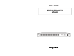
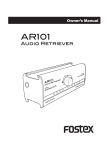
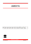
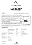
ENGLISH
PROEL S.p.A.
This marking shown on the product or its literature, indicates that it should not be disposed with other household wastes at the end of its
working life. To prevent possible harm to the enviroment or human health from uncontrolled waste disposal, please separate this from other
types of wastes and recycle it responsibly to promote the sustainable reuse of material resources. Household users should contact either
the retailer where they purchased this product, or their local government office, for details of where and how they can take this item for
environmentally safe recycling. Business users should contact their supplier and check the terms and conditions of the purchase contract.
This product should not be mixed with other commercial wastes for disposal.
USER’S MANUAL
(World Headquarters - Factory)
Via alla Ruenia, 37/43
64027 Sant’Omero (TE) - ITALY
Tel. +39 0861 81241 - Fax +39 0861 887862
proelgroup.com
SAFETY AND PRECAUTIONS
• CAUTION - Before using this product read carefully the following safety instructions. Take a look of this manual entirely and preserve it for future
reference.
When using any electric product, basic precautions should always be taken, including the following:
– To reduce the risk, close supervision is necessary when the product is used near children.
– Protect the apparatus from atmospheric agents and keep it away from water, rain and high humidity places.
– This product should be site away from heat sources such as radiators, lamps and any other device that generate heat.
– Care should be taken so that objects and liquids do not go inside the product.
– The product should be connected to a power supply only of the type described on the operating instructions or as marked on the product.
IN CASE OF FAULT
•
–
–
–
•
•
In case of fault or maintenance this product should be inspected only by qualified service personnel when:
Liquids have spilled inside the product.
The product has fallen and been damaged.
The product does not appear to operate normally or exhibits a marked change in performance.
Do not operate on the product, it has no user-serviceable parts inside.
Refer servicing to an authorized maintenance centre.
CE CONFORMITY
• Proel products comply with directive 89/336/EEC (EMC) and following modifications 92/31/EEC and 93/68/EEC, as stated in EN 55103-1 and EN 55103-2
standards and with directive 73/23/EEC (LVD) and following modifications 93/68/EEC, as stated in EN 60065 standard.
PACKAGING, SHIPPING AND COMPLAINT
• This unit package has been submitted to ISTA 1A integrity tests. We suggest you control the unit conditions immediately after unpacking it.
• If any damage is found, immediately advise the dealer. Keep all unit packaging parts to allow inspection.
• Proel is not responsible for any damage that occurs during shipment.
• Products are sold “delivered ex warehouse” and shipment is at charge and risk of the buyer.
• Possible damages to unit should be immediately notified to forwarder. Each complaint for manumitted package should be done within eight days from
product receipt.
WARRANTY AND PRODUCTS RETURN
• Proel products have operating warranty and comply their specifications, as stated by manufacturer.
• Proel warrants all materials, workmanship and proper operation of this product for a period of two years from the original date of purchase. If any defects
are found in the materials or workmanship or if the product fails to function properly during the applicable warranty period, the owner should inform about
these defects the dealer or the distributor, providing receipt or invoice of date of purchase and defect detailed description. This warranty does not extend to
damage resulting from improper installation, misuse, neglect or abuse. Proel S.p.A. will verify damage on returned units, and when the unit has been properly
used and warranty is still valid, then the unit will be replaced or repaired. Proel S.p.A. is not responsible for any "direct damage" or "indirect damage" caused
by product defectiveness.
MAINTENANCE AND DISCLAIMER
• Clean only with dry cloth.
• Proel products have been expressly designed for audio application, with signals in audio range (20Hz to 20kHz). Proel has no liability for damages caused
in case of lack of maintenance, modifications, improper use or improper installation non-applying safety instructions.
• Proel S.p.A. reserves the right to change these specifications at any time without notice.
• Proel S.p.A. declines any liability for damages to objects or persons caused by lacks of maintenance, improper use, installation not performed with safety
precautions and at the state of the art.
CODE: 96MAN0008-ENG
INTRODUCTION
The name DI box comes from direct injection box, that means exactly: To inject a signal directly or take an audio
signal from the source and send it directly to a mixer console or recorder. Direct boxes perform several important
functions: they are designed as impedance matching and signal balancing devices. This means that they take the
high impedance of a guitar or keyboard and ‘transform’ it to the low impedance used in balanced sound systems.
Balanced signals inherently cancel noise and, due to their lower impedance, are capable of very long cable runs.
Balanced signals are the norm in professional recording, broadcast and live sound. By properly matching the
impedance you will enjoy better sound, less noise and an extended frequency response.
DB1-A is an active direct box with an isolation transformer. This means that it includes a powered circuit to convert
the impedance and balance the signal and, with the isolation transformer, a full isolation from grounds avoiding
hum and buzz problems.
The moulded sides make stacking of multiple units easier, and help isolate the case of the DI-box from the stage
both electrically and mechanically. The DB1-A derives its power from the mixing console phantom power, from a
battery or from an external AC/DC adaptor.
CONTROLS AND AUDIO CONNECTION
1. INPUT - (unbalanced JACK or female XLR)
equipment.
Connect the source instrument to this 1/4” jack to receive the signal. The input impedance depends on PAD setting:
1 Mohm with no pad, 47 Kohm with pad insertion.
For best reliability and long life, we recommend you use only high quality alkaline battery.
2. LINK - (unbalanced JACK)
Alternatively to phantom or battery power you can use also an external 9 V DC adaptor. A LINK socket is provided
if you have to power more than one unit installed into a rack.
Connect this 1/4” jack to the input of the backline instrument or monitor amplifier. By factory it is directly connected
at the input; but by changing two internal jumpers (J1 and J2) it is possible to set it as buffered output.
3. PAD - (switches)
The pad switches reduce the input signal to the circuit to ensure a clean and distortion-free signal.
Four steps are possible: 0 dB (no PAD), -10 dB (left only), -20 dB (right only), -30 dB (both). Always use as little as
attenuation as possible to get the best possible signal with reference to the noise floor.
11. 9V BATTERY HOLDER
12. 9VDC INPUT/LINK
RACK MOUNTING
Simply removing the two molded sides and attaching two units with the supplied brackets you can mount two by
two DI boxes into a standard 19” rack.
4. SIGN - (green led)
The SIGN (green) led shows when an input signal is present.
5. CLIP - (red led)
SPECIFICATION
The CLIP (red) led lights up when the signal is at 6 dB before real clip, showing when an excessive input signal is
present. If this led lights up very often, press one or more pad switches to reduces the input signal.
System Type
Input Section
Input Impedance
6. Ø REV - (switch)
Max Input Level
The Ø REV switch reverse the phase of the signal at the balanced output. It can be also used when combining two
sources (mic & DI) on the same instrument to avoid phase cancellation.
Connectors
7. BAL OUTPUT - (male XLR)
This male XLR output connector is the balanced microphone level output of the DI and it is wired with pin-1
ground, pin-2 hot and pin-3 cold. To power the DI box it must be connected to the phantom powered MIC input
of the mixing console. Connecting the DI box to a mixer LINE input the DI box must be powered with battery or
AC/DC adaptor.
8. POWER - (switch)
The power switch is used for both battery and external adaptor power. To avoid battery drain when the unit is not in
use, ensure that this switch is set to the OFF position when storing the DB1-A. The power switch has not influence
when the DB1-A is powered by the phantom power of a MIC channel.
NOTE: To prevent damaging of your speaker and avoid switching noise, first connect the DI box and then
hook up the respective channel or mute the mix channel before activating or connecting the DB1-A.
Output Section
Output
Max. Output Level
Connector
1 channel active DI
1M Ohm (pad at 0 dB)
47k Ohm (pad at -10/-20 dB)
44k Ohm (pad at -30 dB)
+5 dBu (pad at 0 dB)
+15 dBu (pad at -10 dB)
+25 dBu (pad at -20 dB)
+35 dBu (pad at -30 dB)
Two Parallel 1/4" jack connectors and one
parallel XLR connector (unbalanced)
Jack: Tip Hot / Sleeve Ground
XLR female: Pin 2 Hot / Pin1 & 3 Ground
Transformer Balanced (fully isolated)
into 600 Ohms or greater
+3 dBu (for 0.1% THD at 50 Hz)
+5 dBu (for 0.1% THD at 1k Hz)
XLR male: Pin 2 Hot / Pin 3 Cold / Pin1 Ground
< 1 dB
> 60 dB
+14° at 20 Hz, -6° at 20k Hz
< 0.007 %
< -105 dBu unweighted
10 Hz to 100 kHz, +0dB/-1 dB
Controls
Indicators
On/off, Pad -10, Pad -20, Gnd Lift, Ø inv.
On, signal, clip
General
Phantom Power
External AC/DC adaptor
Standalone/Standby
Current consumption
+24 volts DC to +48 volts DC
+9 volts DC
9 volt PP3 type, battery preferably alkaline.
less than 8 mA
Dimensions (W x H x D)
Weight (excluding batteries)
215 x 50 x 125 mm
1 Kg
EXAMPLE (electric bass guitar)
long cable (XLR balanced)
jack-jack link (unbalanced)
9. ON - (green led)
The ON (green) led shows when the DB1-A is powered. If the led doesn’t light, be sure that the phantom power of
the channel where the DB1-A is connected is activated.
10. GND LIFT - (switch)
Use the GND LIFT switch to either connect the ground pin of input and output or keep them completely separated.
Depending on the grounding of the connected devices linking or disconnecting will reduce hum and buzz noises
and prevent ground loops.
NOTE: Always make that sure the GND LIFT is pressed (no ground link) when connecting to speaker
terminals, this prevents accidental short-circuiting of the amplifier output. Also make sure the TIP of the
input jack is connected to the red wire and that the metal chassis of the DB1-A has no contact with other
System Performance
Insertion loss
CMR
Phase distortion
Distortion THD 50÷20k Hz 0dBu
Noise
Frequency Response
hi-z pickup (jack unbal)