1
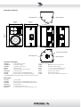
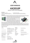
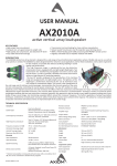
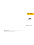
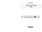
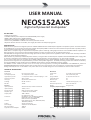
USER MANUAL
NEOS152AXS
digital self-powered loudspeaker
KEY FEATURES
• Premium transducers
• C-AUDIO CLASS D power amplifiers with SWITCH MODE power supply
• 96KHz, 40bit floa ng point C-AUDIO CORE DSP
• Network func onality thru PRONET control so ware
• Access to EQ, DYNAMICS and DELAY and real me parameter control
• Plywood cabinets with die-cast handles, dual-angle pole holder and mul ple flying points
INTRODUCTION
NEOS AXS series represents the highest expression of PROEL GROUP Research & Development applied in loudspeaker systems. A natural evolu on
of the NEOS Series, it incorporates the latest technologies developed by PROEL in advanced sound reinforcement systems able to provide premium
sound, maximum performance and up-to-date features.
NEOS AXS is a complete range of self-powered loudspeaker systems combining cu ng-edge transducers with C-AUDIO CLASS D amplifiers and
digital processors, thus ensuring the best integra on between acous cs and electronics for an op mal performance.
The NEOS AXS are designed for the use both as high-performance mobile systems for live applica ons and as versa le and remotely controllable
systems for advanced fixed installa ons.
All the models are powered by C-AUDIO DA power modules, a new genera on of CLASS D power amplifiers with SWITCH MODE power supply, able
to provide an excep onal sound defini on together with very high dynamics and low distor on in an ultra-compact package.
The on board control electronics are based on the 96KHz, 40bit floa ng point C-AUDIO CORE DSP pla orm, able to op mize further the system
performances through the use of sophis cated EQ, crossover and dynamics algorithms. The CORE processing provides also network func onality
through the PRONET control so ware based on CANBUS communica on protocol (USB2CAN converter needed).
The PRONET control so ware provides access to the major processing features, including full PARAMETRIC and DYNAMIC EQ, advanced
COMPRESSOR/LIMITERS and DELAY, together with the real me control of parameters such as temperature, supply voltage and protec ons.
Se ng created by the user can be saved in user presets that can be recalled through the control so ware or from the unit’s interface.
TECHNICAL SPECIFICATION
AcousƟcal
System type
Low frequency driver
High frequency driver
Frequency response
Horn type
Full range 2-way, vented
15’’ neodymium woofer - 4” VC
2’’ compression driver - tanium diaphragm - 3” VC
40 Hz - 20 kHz
Asymmetrical rotatable horn
Mechanical
Construc on
Finish
Flying hardware
Trapezoidal taper
Monitor taper
15 and 18 mm birch plywood
An -scratch black paint
6 x fly tracks side and rear
10°
42°
Coverage
90°>60° H x 50° V
Pole holder
1 bo om dual angle (0° / 7.5°)
Max SPL
Electrical
Input Impedance
Input Sensi vity
Signal Processing
Amplifier type
Output power
132 dB
Dimensions (W x H x D)
450 x 770 x 490 mm
Weight
36 kg (79.4 lb)
Frequency Response Diagram
Connectors
Controls
Cooling
Power Supply
Max consump on
1/8 power out consump on
20 kohm balanced, 10 kohm unbalanced
+4 dBu / 1.25 V
CORE processing 24 bit / 96 kHz
C- AUDIO Class D with SMPS
1000 + 1000 W
IN - LINK: XLR M - XLR F
NETWORK IN - OUT: ETHERCON® (NE8FAV)
MAIN LINK: PowerCon® (NAC3MPB)
MAIN: PowerCon® (NAC3MPA)
LEVEL, PRESET (FLAT / HPF / MONITOR/ USER)
TERMINATE, GND LIFT
Variable speed DC fan
230 VAC or 120 VAC 50/60 Hz
1650 VA
550 VA
120.0
dBSPL
110.0
100.0
90.0
80.0
70.0
40
50
100
200
500
black = FLAT gray = MONITOR
1k
2k
Hz
5k
10k
20k
MECHANICAL DRAWING
M10 Flying Point
49.2 cm
19.4"
M10 Flying point
45.0 cm
17.7"
78.0 cm
30.7"
Fly Track
Fly Track
Dual Angle Pole Holder
M10 Flying Point
M10 Flying point
OPTIONAL ACCESSORIES
USB2CAN
USB PC-PRONET converter
for speaker suspending:
COVERNE152
Loudspeaker so bag
PLH295
FRE300BK
Loudspeaker ground stand
AC169A
KP210BK
Sub-Speaker pole
AC171
PLX20
Professional ground stand with winch
AC172
KPTNEOS152
Professional Flybar
AC173
NAC3FCA
Neutrik Powercon® BLUE POWER IN PLUG
AC178
NAC3FCB
Neutrik Powercon® WHITE POWER OUT PLUG
AC172E
see www.proel.com for detailed descrip on and other available accessories.
SPARE PARTS
95FTK100
Fly track 100mm
NAC3MPA
NAC3MPB
91AMD152
98ICN152WZ8
98DRI850
Neutrik Powercon® BLUE POWER IN panel socket
Neutrik Powercon® WHITE POWER OUT panel socket
Amplifier Module
15’’ neodymium woofer - 4” VC
2’’ compression driver - tanium diaphragm - 3” VC
M10 Ø 50 mm Truss mount coupler
M10 black shoulder eyebolt
L = 75 cm / 30 inch Aircra cable sling
L = 1.5 m / 4.9 Aircra cable sling
Screw pin anchor shackle
Double point flying stud
36 cm / 14.2 inch Aircra Cable with Stud
POWER PANEL
MAINS IN - Powercon® NAC3FCA power input connector (blue). To switch the amplifier on, insert the Powercon® connector and turn it in a
clockwise direc on into the ON posi on. To switch the amplifier off, pull back the switch on the connector and turn the connector in an an clockwise direc on into the POWER OFF posi on.
NOTE: In the case of product failure or fuse replacement, disconnect the unit completely from the mains power. The power cable must only be
connected to a socket adequate to the specifica ons indicated on the amplifier unit. The power supply must be protected by a suitably rated
thermo-magne c breaker. Preferably use a suitable switch to power on the whole audio system leaving the Powercon® always connected to each
speaker, this simple trick extend the life of the Powercon® connectors.
POWER OUT - Powercon® NAC3FCB power output connector (grey). This is connected in parallel with the MAINS ~ / IN; the maximum load
applicable is 10A/230V ~.
NOTE: the number of speaker units that can be connected in sequence depends by the sum of the speaker consump on current.
PRODUCT LABEL - In this label are wri en the most important informa on about the ac ve loudspeaker, model, line voltage, consump on, serial
number.
CONTROL PANEL
ON - This LED indicates power on status.
PROT - This red LED lights when the amplifier module is in protect mode for an internal fault and, consequently, the amplifier is muted.
SIGN LIMIT - This LED lights green to indicate the presence of the signal and lights red when an internal limiter reduces the input level.
LEVEL - This poten ometer a enuates the input level in the most useful range star ng from 0dB to -20dB with a -6dB a enua on at the centre.
MODE - This bu on select one of the four preset available, if it is pressed when the unit is switched on it forces the internal DSP to re-assign an
ID to the unit for the PRONET remote control opera on.
FLAT - This LED lights when the FLAT preset is selected. This is the basic factory preset of the loudspeaker and it can be used for all music genre.
HPF - This LED lights when the HPF preset is selected, which is the FLAT preset with an high-pass filter added. Use this preset when the loudspeaker
is combined with subwoofers.
MON - This LED lights when the MONITOR preset is selected. Use this preset if the loudspeaker is used as a stage monitor.
USER - This LED lights when the USER preset is loaded. This preset corresponds to USER MEMORY no. 1 of the DSP and, as a factory se ng, it’s
the same to FLAT. If you want to modify it, you have to connect the unit to a PC, edit the parameters with PRONET so ware and save them into
USER MEMORY no. 1.
NETWORK IN/OUT - These are a standard RJ45 CAT5 connectors (with op onal NEUTRIK NE8MC RJ45 cable connector carrier), used for PRONET
network transmission of remote control data over long distance or mul ple unit applica ons.
TERMINATE - In a PRONET network the last connected device must be terminated (with an inner load resistance) especially in a long run cabling:
press this switch if you want to terminate the unit.
INPUT - Audio signal input with locking XLR connector. It has a fully electronically balanced circuitry including AD conversion for the best S/N ra o
and input headroom.
LINK - A direct connec on from the input connector to link other speakers with same audio signal.
GND LIFT - This switch li the ground of the balanced audio inputs from the earth-ground of the amplifier module.
PRONET
PRONET so ware has been designed by Proel’s Research & Development Department to easily control a single unit or a network of devices, like
ac ve loudspeakers or speaker processors, equipped with the C-AUDIO CORE digital processing pla orm.
PRONET has been developed in collabora on with sound engineers and sound designers, in order to offer an “easy-to-use” tool to setup and
manage your audio system. With PRONET you can visualize signal levels, monitor internal status and edit all the parameters of each connected
device.
Download the PRONET app from the PROEL website at h p://www.proel.com clicking on support sec on.
The NEOS AXS loudspeaker devices can be connected using the network connec on, in this case the PROEL USB2CAN converter op onal accessory
is needed. The first me you connect a device with the USB2CAN converter, Windows O.S. will ask you to install the driver files, which you can
find in the Driver folder within the Pronet applica on folder (by default is C:\Program Files\Proel\Pronet\Driver, or if you changed it <your path>\
Driver). Please refer also to “Installa on” and “Drivers” paragraphs in the Pronet documenta on.
The PRONET NETWORK is based on a robust, reliable and fast communica on protocol called CANBUS. The devices in a PRONET NETWORK are
connected together with a “linear bus topology”. The USB2CAN converter must be connected to the network input of the first device, the network
output of the first device is connected to the input of the second and so on. For the network connec ons simple RJ45 cat.5 or cat.6 ethernet
cables can be used (please don’t confuse a ethernet network with a PRONET network these are completely different and must be fully separated
also both use the same kind of cable).
The beginning and the end of a PRONET NETWORK must be terminated. One side is terminated by the USB2CAN converter, the other side must
be terminated pressing the TERMINATE switch on the last device. All devices between these two points must have the TERMINATE switch li ed.
Assign the ID number
To work properly in a PRONET network each connected device must have a unique iden fier number, called ID. By default the USB2CAN PC
controller has ID=0 and there can be only one PC controller. Every other device connected must have its own unique ID equal or greater than 1:
in the network cannot exist two devices with the same ID.
An ID number is assigned automa cally to each devices when they are turned on for the first me connected to a network.
In order to correctly assign a new available ID to each device for working properly in a Pronet network, follow these instruc ons:
1. Switch off all the devices.
2. Connect them correctly to the network cables.
3. “TERMINATE” the latest device in the network connec on.
4. Switch on the first device keep pressed “PRESET” bu on on the control panel.
5. Leaving the previous device switched on, repeat the previous opera on on the next device, un l the latest device is turned on.
The “Assign ID” procedure for a device makes the internal network controller to perform two opera ons: reset the current ID; search the first free
ID in the network, star ng from ID=1. If no other devices are connected (and powered on), the controller assume ID=1, that is the first free ID,
otherwise it searches the next one le free.
These opera ons ensure that every device has it’s own unique ID, if you need to add a new device to the network you simply repeat the opera on
of step 4. Every device maintains its ID also when it is turned-off, because the iden fier is stored in the internal memory and it is cleared only by
another “Assign ID” step, as explained above. This means that if your network is made always of the same devices the assigning ID procedure must
be executed only the first me the system is turned on.
See the more detailed instruc on about PRONET on the documenta on downloadable from the web site: www.proel.com.
LIMITED WARRANTY
Proel warrants all materials, workmanship and proper opera on of this product for a period of two years from the original date of purchase. If any defects are found
in the materials or workmanship or if the product fails to func on properly during the applicable warranty period, the owner should inform about these defects the
dealer or the distributor, providing receipt or invoice of date of purchase and defect detailed descrip on. This warranty does not extend to damage resul ng from
improper installa on, misuse, neglect or abuse. Proel S.p.A. will verify damage on returned units, and when the unit has been properly used and warranty is s ll
valid, then the unit will be replaced or repaired. Proel S.p.A. is not responsible for any “direct damage” or “indirect damage” caused by product defec veness.
• This unit package has been submi ed to ISTA 1A integrity tests. We suggest you control the unit condi ons immediately a er unpacking it.
• If any damage is found, immediately advise the dealer. Keep all unit packaging parts to allow inspec on.
• Proel is not responsible for any damage that occurs during shipment.
• Products are sold “delivered ex warehouse” and shipment is at charge and risk of the buyer.
• Possible damages to unit should be immediately no fied to forwarder. Each complaint for package tampered with should be done within eight days from product
receipt.
SAFETY INSTRUCTIONS
– To reduce the risk, close supervision is necessary when the product is used near children.
– Protect the apparatus from atmospheric agents and keep it away from water, rain and high humidity places.
– This product should be site away from heat sources such as radiators, lamps and any other device that generate heat.
– This product should be located so that its loca on or posi on does not interfere with its proper ven la on and hea ng dissipa on.
– Care should be taken so that objects and liquids do not go inside the product.
– The product should be connected to a power supply mains line only of the type described on the opera ng instruc ons or as marked on the product. Connect the
apparatus to a power supply using only power cord included making always sure it is in good condi ons.
– WARNING: The mains plug is used as disconnect device, the disconnect device shall remain readily operable.
– Do not cancel the safety feature assured by means of a polarized line plug (one blade wider than the other) or with a earth connec on.
– Make sure that power supply mains line has a proper earth connec on.
– Power supply cord should be unplugged from the outlet during strong thunderstorm or when le unused for a long period of me.
CE CONFORMITY
Proel products comply with direc ve 2004/108/EC (EMC), as stated in EN 55103-1 and EN 55103-2 standards and with direc ve 2006/95/CE (LVD), as stated in EN
60065 standard.
PROEL S.p.A. (World Headquarter) - Via alla Ruenia 37/43 - 64027 Sant’Omero (Te) - ITALY
Tel: +39 0861 81241 Fax: +39 0861 887862 www.proel.com