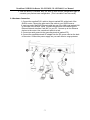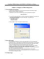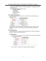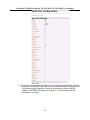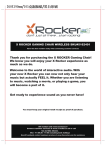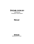
1
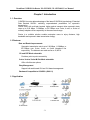
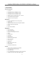
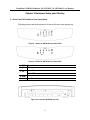
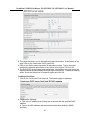
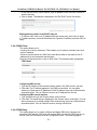
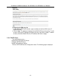
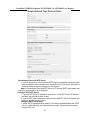
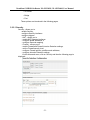
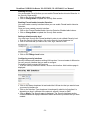
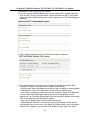
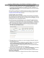
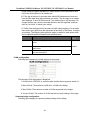
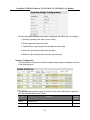
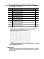
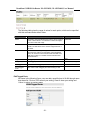
G.SHDSL.bis Router
User Manual
XL-GRT402S
XL-GRT404S
XtendLan G.SHDSL.bis Router XL-GRT402S, XL-GRT404S, User Manual
Chapter 1 Introduction
1.1 Overview
G.SHDSL.bis router takes advantage of the latest G.SHDSL.bis technology- Extended
Rate Bonded SHDSL- unfolding unprecedented possibilities for symmetric
transmission.
Router came with multi-pair bonded; higher packet transport allow symmetric data
rates up to 5.69 Mbps, 11.38Mbps, or 22.76Mbps over 2-wire, 4-wire, or 8-wire of
ordinary telephone lines respectively at the same reach range.
Router is a suitable solution enables enterprise users to enjoy distance, high
bandwidth and symmetric data transmission hungry.
1.2 Features
Rate and Reach Improvements
Symmetric transmission rate is up to 5.69 Mbps, 11.38Mbps, or
22.76Mbps over 2-wire, 4-wire, or 8-wire telephone line
respectively. The distance can reach as far as 12,000 ft.
CO and CPE Mode selectable
Provide a point-to-point connectivity
2-wire / 4-wire/ 8-wire M-Pair Mode selectable
Offer a flexible rate options
Easy Management
Support both web-based GUI and CLI-based management.
Backward Compatible to G.SHDSL (G.991.2)
1.3 Application
-2-
XtendLan G.SHDSL.bis Router XL-GRT402S, XL-GRT404S, User Manual
1.4 Specification
Standard Compliance
•
ITU-T G.991.2
•
Transmission rate up to 5.69 Mbps on 2-wire
•
Transmission rate up to 11.38 Mbps on 4-wire
•
Transmission rate up to 22.76 Mbps on 8-wire
•
Support of Annex A, Annex B, Annex F, and
•
Auto load balancing with bonded pairs
•
Support point-to-point configuration
Annex G
Maintenance
•
Firmware upgradeable via FTP or TFTP (optional)
•
Support Telnet
•
Support ATM OAM F5 End to End and Segment loopbacks
•
Statistics on DSL link and data ports
•
Sys-log
•
HTTP web downloadable
Management
•
Password protection
•
PAP and CHAP support
•
Remote access management via telnet
•
SNMPv1
•
Firewall Security
•
Packet Filter
•
Denial of Service
•
Stateful Packet Inspection (SPI)
•
Attack Alert and log
•
Access Control
•
Real time log
•
MIB-II (RFC 1213, RFC 1573)
•
Web based GUI
•
Command Line Interface (CLI)
Protocol
•
Support ATM over G.SHDSL.bis and G.SHDSL
•
MAC bridging(IEEE 802.3 and 802.1D)
•
PPPoE (RFC 2416)
•
RFC 1483/2684 Bridged encapsulation (routing mode optional)
•
IP support TCP, RIPv1, RIPv2, UDP, ICMP, ARP, RTP
-3-
XtendLan G.SHDSL.bis Router XL-GRT402S, XL-GRT404S, User Manual
•
IEEE802.1P Priority Output Queuing
•
IEEE 802.1Q VLAN
•
IEEE802.3u Fast Ethernet 100BaseT
•
MAC Filtering
•
QoS support VBR-rt, VBR-nrt, CBR and UBR
•
Support 8 PVCs
•
NAT/PAT support
•
DHCP client/server and DHCP relay functionality
•
VPN pass-through IPSec and L2TP
•
Support IGMP Snooping
•
DMZ support
•
IPSec VPN Support
•
Support Port-based VLAN
LED
•
LED indicator; power, DSL links, Alarm, Ethernet ports and CO/CPE mode
Hardware Interface
•
DSL interface: 2/4 wires one RJ-11 jack. 8 wires two RJ-11 jacks
•
Ethernet interface: four RJ-45 jack; 10/100BaseT auto sensing and crossover
•
AC power adapter (100VAC ~ 240VAC, 50-60Hz)
•
One craft Interface for local console access (CID)
Dimensions & Weight
•
Dimensions: 35mm(H)×210mm(W)×193mm(D)
•
Weight: 914g
Operating Requirements
•
Operating temperature: 0C to +50C
•
Operating humidity: 5% to 90% RH non-condensing
-4-
XtendLan G.SHDSL.bis Router XL-GRT402S, XL-GRT404S, User Manual
Chapter 2 Hardware Setup pand Startup
2.1 Front Panel LED and Rear Panel description
Following pictures are the front panel of 4-wire and 8-wire router respectively.
Figure 2-1 8-wire XL-GRT402S Front Panel LED
Figure 2-2 4-wire XL-GRT404S Front Panel LED
1. PWR Power Indicator
2. DSL DSL loop
3. CO
4. ALM
5. LAN
On--- CO
Off--- CPE
Alarm for error
On---Ethernet Link connected
Figure 2-3 8-wire XL-GRT402S rear view
-5-
XtendLan G.SHDSL.bis Router XL-GRT402S, XL-GRT404S, User Manual
Figure 2-4 4-wire XL-GRT404S rear view
1. DC IN:
2. Reset Button:
3. CID:
4. LAN:
5. DSL 1 to 4
6. FG
Power Adapter Input
Reset device to factory default setting
Connected to PC serial port for console
Connected to Ethernet Port
Connected to loop 1 to 4
Connected to ground wire
2.2 DSL Connectors Description
DSL Connectors on back of the unit, 2 RJ-11 sockets.
RJ-11 uses a 6P4C connector and cable. The cable has 4 wires and we are using them
for 2 pairs of DSL connection.
Pin 1
Pin 2
Pin 3
Pin 4
Pin 5
Pin 6
Not used.
Tip for DSL pair 2 or 4.
Tip for DSL pair 1 or 3
Ring for DSL pair 1 or 3
Ring for DSL pair 2 or 4
Not used.
2.3 Restore Factory Defaults/Reboot Button
Press the reset button to reset the ROUTER to its factory-default settings (default
configuration file will be uploaded). If you forget your password or cannot access the
device, you will need to reset the device to the default settings. The procedure shows
as follows:
1. Power off the Modem.
2. Press the reset default button.
3. Power on the Modem, and watch the Front Panel of the Modem.
4. While the “CPE LED” LED" blinks very quickly, please release the button.
(If you press the button to long, recall won't work, this is to prevent the user might
hold the button all the time)
-6-
XtendLan G.SHDSL.bis Router XL-GRT402S, XL-GRT404S, User Manual
5. Now the factory is recalled, then you have to save current configuration again to
overwrite your previous user configuration. (This is so-called "one-time recall")
2.4 Hardware Connection
1. Connect the supplied RJ11 cable to the port marked DSL at the back of the
SHDSL router. Connect the other end of the cable to your SHDSL source.
2. Insert one end of the RJ45 Ethernet cable into one of the LAN ports marked LAN
on the back of the SHDSL router. Connect the other end of the cable into the
Ethernet Network Interface Card (NIC) in your PC. Connect up to four Ethernet
devices to the router. Use a crossover cable for a hub.
3. Connect an earth ground to the grounding terminal (marked FG).
4. Connect the supplied external AC adapter into the DC power outlet on the back
of the router. Connect the power supply into your wall outlet or surge protector.
-7-
XtendLan G.SHDSL.bis Router XL-GRT402S, XL-GRT404S, User Manual
Chapter 3 Configure via Web management
3.1 Accessing Web management
To access Web management on the router that has been booted with an image
containing a factory default configuration:
1. Attach a PC to one of the LAN interfaces. At your web browser, enter the
http://192.168.1.1
2. If you first time login the Web, you will see a login box is displayed. You must enter
your username and password to access the pages. The default User
name/Password as follows
User Name: admin
Password: admin
3. Click on OK. You are now ready to configure router.
3.2 About Web pages
Web management provides a series of web pages that you can use to setup and
configure the router. These pages are organized into three main topics. You can select
each of the following topics from the menu on the left-hand side of the main window:
• Status: information about the current setup and status of the system.
• System: The System section lets you carry out system commands like Firmware
Update, Backup/Restore, Save configuration, Authentication and restart.
• Configuration: information about the current configuration of various system features
with options to change the configuration.
The exact information displayed on each web page depends on the specific
configuration that you are using. The following sections give you a general overview of
the setup and configuration details.
3.2.1 Status Pages
-8-
XtendLan G.SHDSL.bis Router XL-GRT402S, XL-GRT404S, User Manual
The Status homepage contains information about the current configuration of router.
It provides an overview of the current image configuration. The page contains the
following sections:
The Status page display following sections:
1. system information
2. physical port
3. Routing table
4. Network interface
5. event log
3.2.1.1 System information
Click System Information on Status menu, and then System information page is
displayed promptly.
This page shows system information, including MAC adsdress, Firmware version,
Transceiver information, LAN IP address and subnet mask, MAC address and
UP-Time.
3.2.1.2 Physical Port
This option allows you to configure the ports available on your Router, depending on
the type of image that you are going to boot.
Configuring ports
1. From the Status menu, click on Port Configuration. The physical ports available
on your device are displayed.
2. Click on Shdsl. The Shdsl Port Configuration page is displayed:
-9-
XtendLan G.SHDSL.bis Router XL-GRT402S, XL-GRT404S, User Manual
3. You can carry out advanced configuration of your Ethernet port attributes. From the
Shdsl Port Configuration page, click on View advanced attributes. The Shdsl Port
Configuration page is displayed. “Shdsl” is the default port name of SHDSL
created in ROUTER where stands for ATM port. You can configure SHDSL
parameters in this page.
-10-
XtendLan G.SHDSL.bis Router XL-GRT402S, XL-GRT404S, User Manual
4. In the Unit Id drop-down menu, you can set the device as CO or CPE, and then
click on Apply to submit your setting.
-11-
XtendLan G.SHDSL.bis Router XL-GRT402S, XL-GRT404S, User Manual
5. If to set ROUTER’s Wire Pair mode, Click on Wire Pair drop-down list to select
the Wire Pair number needed. After that, click on Apply to submit your setting.
Wire Mode
2-WireMode
DSL Pair to Use
1
4-WireMode
6-WireMode
8-WireMode
1,2
1,2,3
1,2,3,4
Illustration
6. If to set the maximum and minimum line rate, input the Max Line Rate and Min
Line Rate respectively (where values range from 200kbps to 5704kbps) and then
click on Apply to submit your setting. After the handshaking between STU-R and
STU-C devices, the actual transmission rate will be presented in the Current Tx
Rate attribute.
7. If to configure a specified Ethernet port, click on eth1~eth4 via Physical Port
Table and then the specified Ethernet Port Configuration page is displayed:
-12-
XtendLan G.SHDSL.bis Router XL-GRT402S, XL-GRT404S, User Manual
The page displays basic port attributes for the Ethernet port on your Router.
8. You can view or carry out advanced configuration for your Ethernet port
attributes. For instance, Click View advanced attributes on Eth1t Port
Configuration page, and then The Advanced Eth1t Port Configuration page is
displayed.
9. Set the Ethernet port as enabled or disabled via Admin Status drop-down list,
and then click on Apply to update the advanced configuration, or Reset to revert
back to the default advanced configuration settings. Click on the Return to basic
attribute list to return to the Eth1 Port Configuration page.
3.2.1.3 Routing Table
Routing Table is a matrix with a network control protocol, which gives the hierarchy of
link routing at each node.
The Routing Table screen allows you to view the routing table built in the device.
-13-
XtendLan G.SHDSL.bis Router XL-GRT402S, XL-GRT404S, User Manual
If to create an IP route, refer to the IP Routes section on Advanced menu.
3.2.1.4 Network Interface
If to view the statistics on Bridge/Router Interfaces, select a specified interface to
invoke the Bridge/Router Interface page.
Following figure shows the statistics on the interface, rfc1483-0..
Click Configure WAN connections to configure WAN connections, referring to the
WAN connections section on Setup pages.
-14-
XtendLan G.SHDSL.bis Router XL-GRT402S, XL-GRT404S, User Manual
3.2.1.5 Event Log
Click on Event Log, the following page is displayed as follows:
This page displays a table containing all configuration errors experienced by your
Router during a current session. 3 types of logs can be selected via select a log
drop-down list.
All Event: Shows all events occurred.
Config errors: Shows error messages regarding configuration(s) which the system
DOES NOT allow to change
Syslog Messages: Shows all messages regarding system actions other then
Config errors
3.2.2 Quick Setup page
The Quick Setup page allow user to configure VPI/VCI in this device. The procedure to
set VPI/VCI is shown as follows:
1. Enter one service’s VPI and VCI on the fields repetitively.
2. Click on Apply to submit your setting or Reset to clear your setting.
3. If to create or delete WAN services, click the Click here to Add Delete WAN
Services link.
-15-
XtendLan G.SHDSL.bis Router XL-GRT402S, XL-GRT404S, User Manual
3.2.3 System Pages
Click on System menu, the following options appear:
The System menu contains options including, Firmware Update, Backup/Restore and
Restart Router, Save configuration and Authentication. They will be introduced in the
following sections.
3.2.3.1 Save config
To save your current configuration to Flash ROM:
1. From the System menu, click on Save configuration. The following page is
displayed:
2. Click on Save to save your current configuration in the device.
After a short time the configuration is saved and the following confirmation message
is displayed: Saved information model to file //flashfs/im.conf
-16-
XtendLan G.SHDSL.bis Router XL-GRT402S, XL-GRT404S, User Manual
3.2.3.2 Authentication
This option allows you to administer accounts for users who access the Router. Click
on Authentication via the System menu. The following page is displayed:
Creating a new login account
1. Click on the Create a new user. The following page is displayed:
2. Type details for the new user into the username, password and comment text boxes,
and select a May login? Option:
• true means that the user can login but not dialing
• false means that the user can not login
3. Click on the Create . The Authentication page is displayed. The table now contains
details for the user that you have just created.
Editing/deleting a login account
1. The Authentication page table contains an Edit user hyperlink for each user account
entry. Click on a link. The following page is displayed:
This page allows you to:
• update details for a specific user account. Modify the necessary text boxes then
-17-
XtendLan G.SHDSL.bis Router XL-GRT402S, XL-GRT404S, User Manual
click on the Apply .
• delete a user account. Click on the Delete this user button.
2. Once you have edited or deleted a user account, the Authentication page is
displayed and the table reflects any changes that you have made on the edit user
page.
3.2.3.3 Firmware Update
This option allows you to upload firmware images to Router using HTTP.
1. From the System menu, click Firmware update. The following page is displayed:
2. Type in the location of the new firmware image that you want to upload, or use
Browse to browse and select the file. Click on Update.
3. Once the file has been uploaded to the RAM of your device, it is written to Flash
ROM. A status page is displayed confirming that the upload is complete and telling
you how much of the file (in bytes and as a percentage) has been written to Flash
ROM.
4. Once the file has been written to Flash, the Firmware Update page is refreshed. The
page confirms completion of the update and asks you to restart your Router in order
to use the new firmware. Click on Restart Router from system menu.
Note: Please do not power-off the device while updating firmware or saving your
configuration, power-off the device while updating the system might cause the
device crashed.
3.2.3.4 Backup/Restore
This page allows you to backup your configuration to, or restore it from your computer.
Backing up your configuration
1. From the System menu, click on Backup/restore. The following page is displayed:
2. From the Backup Configuration section, click on the Backup. The File Download
window is displayed and then select the Save. The Save As window will prompt and
-18-
XtendLan G.SHDSL.bis Router XL-GRT402S, XL-GRT404S, User Manual
select a file in which to save your backup configuration. Click on Save.
Restoring your configuration
1. From the System menu, click on Backup/restore.
2. In the Restore Configuration section, click in the Configuration File text box and type
the network path of the file that you wish to restore. If you do not know the path
details, click on Browse and locate the file using the Choose file box.
3. Click on Restore. The page is refreshed with a Configuration Restored message and
details of the number of bytes uploaded.
3.2.3.5 Restart
This page allows you to restart your Router. It has the same effect as resetting your
Router by pressing the appropriate reset button on the hardware.
1. From the System menu, click on Restart Router. The following page is displayed:
2. Click on Restart to reset your Router. The Restart page also provides you with the
option of restarting and restoring the factory default settings. Click in the Reset to
factory default settings box to check it, and then click on the Restart. Read the
console status output to check how the reset is progressing.
3. Once the login and password prompt is displayed at the console, you can login as
usual (with login = admin, password = admin), then refresh the browser that is running
Web. The Status page is displayed and your Router has been reset.
3.2.4 Configuration pages
The Configuration menu contains options for configuring features on ROUTER
including basic LAN and WAN connections and DHCP and DNS settings.
Note: Most of the features contain sensible default settings. You are unlikely to have to
reconfigure every feature included in the Configuration menu. From the left-hand menu,
click on Configuration. The following sub-headings are displayed:
• LAN connections: allows you to edit your LAN port IP address, create and edit a
secondary IP address and create new LAN services.
• WAN connections: allow you to create, edit and delete WAN services.
• DHCP server: allow you to enable, disable and configure your DHCP server.
-19-
XtendLan G.SHDSL.bis Router XL-GRT402S, XL-GRT404S, User Manual
• DHCP relay: allow you to enable, disable and configure your DHCP relay.
• DNS client: allow you to enable, disable and configure DNS client.
• DNS relay: allow you to enable, disable and configure DNS relay.
• SNTP client: allow you to configure Simple Network Time Protocol at Client side.
(Please point to the SNTP server, contact with your ISP provider.)
3.2.4.1 LAN connections
This option allows you to:
• configure the IP address and subnet of the default LAN connection to the Router.
• configure a secondary IP address on the same subnet as the primary IP address.
• create virtual interfaces; multiple virtual interfaces can be associated with the existing
primary LAN interface.
From the Configuration menu, click on LAN connections. The following page is
displayed:
Configuring primary and secondary LAN connections
1 The Default LAN Port section contains two subsections:
a. IP address and subnet mask details of your primary LAN connection. To edit
these details, click Change default LAN port IP address and type new primary
address details.
b. Secondary IP address details. To create/configure a secondary IP address, click
in the Secondary IP Address text box and type new address details.
-20-
XtendLan G.SHDSL.bis Router XL-GRT402S, XL-GRT404S, User Manual
1. Once
you have configured the IP address(es), click on the Apply . A message is
displayed confirming that your address information is being updated. If you
have changed the primary IP address, you may need to enter the new address
in your web browser address box.
Creating virtual interfaces
1. Click on the Create a new virtual interface... hyperlink at the bottom of the LAN
connections page. On the Create virtual interface page, type the IP address and
netmask of the virtual interface, and then click on the Apply.
2. The LAN connections page is displayed. The virtual interfaces section contains a
table listing the names of the virtual interface(s). Each virtual interface is called
item# by default.
3. Each virtual interface name has an Edit and a Delete link associated with it. To
edit a service:
a. Click on the Edit link.
b. Change the options for the existing virtual interface, then click on Change. The
page is reset and the new values are displayed.
To delete a service:
a. Click on the Delete link.
b. Check the details displayed, and then click on the Delete this connection
-21-
XtendLan G.SHDSL.bis Router XL-GRT402S, XL-GRT404S, User Manual
button.
3.2.4.2 WAN Connection
This option allows you to create and configure WAN connections for Your Router.
You can also create virtual interfaces on routed services. Click on WAN
connections via Configuration menu, the WAN connections page is displayed:
Creating a WAN service
1. Click on Create a new service. A page is displayed containing a list of WAN service
options.
2. Select an option, and then click on Configure. You need to add detailed configuration
information about the WAN service that you are creating.
3. Click on
. The WAN connections page is displayed. The table now contains
details of the service that you have just created.
Editing a WAN service
1. Click on the Edit link for a specific service. The WAN connection:
edit page is displayed.
-22-
XtendLan G.SHDSL.bis Router XL-GRT402S, XL-GRT404S, User Manual
2. Change the values for the existing service. If you want to carry out advanced editing,
click on the links at the top of the edit page. The links that appear depend on the type
of service that you are configuring. For example, for an RFC 1483 routed service,
you can choose from the following advanced editing links:
Edit ‘Service’
Edit ‘PPPoE’
Edit ‘Atm Channel’
3. Click on Change. The edit page is displayed and changes are applied to the
service.
Deleting a WAN service
1. At the WAN connections page, click on the Delete link for a specific service. The
WAN connection: delete page is displayed.
2. Check the details displayed, and then click on the Delete this connection button.
Creating a virtual interface (routed services only)
1. Click on the Virtual I/f link for a specific service. The Virtual interface page is
displayed.
2. Click on the Create a new virtual interface... hyperlink. On the Create virtual interface
page, type the IP address and netmask of the virtual interface, and then click on the
Apply.
-23-
XtendLan G.SHDSL.bis Router XL-GRT402S, XL-GRT404S, User Manual
3. The WAN connections page is displayed. If you click on the Virtual I/f link, the Virtual
interface page displays a table listing the names of existing virtual interfaces. Each
virtual interface is called item# by default.
3.2.4.3 DHCP Server
This option allows you to enable/disable the DHCP server and create configure and
delete DHCP server subnets and DHCP fixed IP /MAC mappings. Click on DHCP
server from the Configuration menu the following page is displayed:
Enabling/disabling the DHCP server
The DHCP server is enabled by default. If to disable the DHCP server, click on Disable.
Note: If DHCP relay is enabled, DHCP server will be disabled by default. You can not
enable DHCP server unless you disable DHCP relay.
Creating a DHCP server subnet
1. Click on the Create new Subnet link. The following page is displayed:
-24-
XtendLan G.SHDSL.bis Router XL-GRT402S, XL-GRT404S, User Manual
2. This page allows you to:
a. Set the value and netmask of the subnet (either manually or by selecting an IP
interface whose value and mask is used instead), and set the maximum and
default lease times.
b. Set the DHCP address range (or use a default range of 20 addresses).
c. Set the Primary and Secondary DNS Server addresses or set your System to give
out its own IP address as the DNS Server address.
d. Set your Router to give out its own IP address as the default Gateway address.
3. Once you have entered new configuration details for your DHCP server, click on OK .
The DHCP Server page is displayed, containing details of your new subnet.
Editing a DHCP subnet
1. Click on the Advanced Options link for a specific subnet. The Edit DHCP server
subnet page is displayed. This allows you to edit all of the values that were set
when the subnet was created.
-25-
XtendLan G.SHDSL.bis Router XL-GRT402S, XL-GRT404S, User Manual
2. This page also allows you to add additional option information. At the bottom of the
page, click on the Create new DHCP option link.
3. Click on the Option name drop-down list and select a name. Type a value that
matches the selected option name in the Option value text box. Click on OK .
4. The Edit DHCP server subnet page is displayed, and details of you new option are
displayed under the sub-heading Additional option information. To delete an existing
option, check the Delete box for a specific option and click OK.
Creating a fixed host
1. Click on the Create new Fixed Host link. The following page is displayed:
2. Complete the following:
a. Type in the IP address that will be given to the host with the specified MAC
address.
b. Type in the MAC address and the maximum lease time (default is 86400
seconds).
-26-
XtendLan G.SHDSL.bis Router XL-GRT402S, XL-GRT404S, User Manual
3. Click on OK. The DHCP Server page is displayed, and details of your new fixed host
are displayed under the sub-heading Existing DHCP fixed IP/MAC mappings. To edit
a fixed mapping, click on the IP address, MAC address or max lease time, type a
new entry and click Apply . To delete a fixed mapping, check the Delete box for a
specific mapping and click Apply.
3.2.4.4 DHCP Relay
This option allows you to:
• enable/disable DHCP relay.
• add DHCP servers to the DHCP relay list.
• configure/delete server entries on the DHCP relay list. Click on DHCP relay from the
Configuration menu. The following page is displayed:
Enabling/disabling DHCP relay
1. The DHCP relay is currently disabled. If you click on the Enable button, DHCP
server is disabled and the button changes to Enable.
Note: If DHCP server is enabled, DHCP relay will be disabled by default. You can not
enable DHCP relay unless you disable DHCP server.
Adding a DHCP server to the DHCP relay list
-27-
XtendLan G.SHDSL.bis Router XL-GRT402S, XL-GRT404S, User Manual
1. In the Add new DHCP server section, type an address in the New DHCP server IP
address text box.
2. Click on Apply. The address is displayed in the Edit DHCP server list section.
Editing/deleting entries in the DHCP relay list
1. To edit an entry, click on an IP address and type a new entry, then click on Apply
2. To delete an entry, check the Delete box for a specific IP address, and then click on
Apply.
3.2.4.5 DNS Client
This option allows you to:
• create a list of server addresses. This enables you to retrieve a domain name for a
given IP address.
• create a domain search list. DNS client uses this list when a user asks for the IP
address list for an incomplete domain name.
From the Configuration menu, click on DNS client. The following page is displayed:
Configuring DNS servers
1. Type the IP address of the unknown domain name in the DNS servers: text box.
2. Click Add. The IP address appears in the DNS servers table. You can add a
maximum of three server IP addresses. Each IP address entry has a Delete button
associated with it. Click on Delete to remove an IP address from this list.
Configuring DNS search domains
1. Type a search string in the Domain search order: text box.
2. Click Add. The search string is displayed in the Domain search order table. You can
add a maximum of six search strings. Each search string entry has a Delete button
associated with it. Click on Delete to remove a string from this list.
3.2.4.6 DNS Relay
This option allows you to create, configure and delete DNS relay’s primary and
secondary DNS servers. DNS relay can forward DNS queries to the DNS servers on
this list. Click on DNS Relay from the Configuration menu. The following page is
-28-
XtendLan G.SHDSL.bis Router XL-GRT402S, XL-GRT404S, User Manual
displayed:
Configuring the DNS relay list
1. In the Add new DNS server section, type an address in the New DNS server IP
address text box.
2. Click on Apply. The address is displayed in the Edit DHCP server list section. To edit
an entry, click on an IP address and type a new entry, then click on Apply. To delete
an entry, check the Delete? Box for a IP address, then click on Apply.
3.2.4.7 SNTP Client
The option allows you to:
Synchronize Client with NTP Server
Configure SNTP-NTP Server
System clock setting by manual
Click on SNTP client from the Configuration menu. The following page is displayed:
-29-
XtendLan G.SHDSL.bis Router XL-GRT402S, XL-GRT404S, User Manual
Synchronize Client with NTP Server
1. Click on Synchronize that forces the SNTP client to immediately synchronize the
local time with the server located in the association list (if unicast) or, if anycast is
enabled, initiate an anycast sequence to the network.
Note: to Synchronize Client with NTP Server, NTP servers, SNTP client mode, and
local time zone should be pre-configured.
Configure SNTP-NTP Server
1. Type the NTP Sever IP address in the text box of Add NTP Server IP Address,
and then click on Add to make it valid.
2. Type the NTP Sever Hostname in the text box of Add NTP Sever Hostname, and
then click on Add to make it valid.
Configure SNTP client mode
1. Select SNTP Synchronization mode(s): This action enables/disables the STNP
client in a particular time synchronous access mode. There are three modes to
choose from, and
-30-
XtendLan G.SHDSL.bis Router XL-GRT402S, XL-GRT404S, User Manual
each mode has enable and disable options:
a. Unicast mode:
• Enable - the mode uses a unicast server and the IP address or hostname in
the SNTP server association list is used to synchronize the client time with the
server. The SNTP client attempts to contact the specific server in the
association in order
to receive a timestamp when the sntpclient sync command is issued.
• Disable - the unicast server is removed from the association list.
b. Broadcast mode:
• Enable - allows the SNTP client to accept time synchronization broadcast
packets from an SNTP server located on the network, and updated the local
system time accordingly.
• Disable - stops synchronization via broadcast mode
c. Anycast Mode:
• Enable - the SNTP client sends time synchronized broadcast packets to the
network and subsequently expects a reply from a valid timeserver. The client
then uses the first reply it receives to establish a link for future sync operations
in unicast mode.
This server will then be added to the server association list. The client ignores
any later replies from servers after the first one is received.
The enabled anycast mode takes precedence over any entries currently in the
associations list when the sntpclient sync command is issued. The entry will
then be substituted for any existing entry in the unicast association list.
• Disable - stops synchronization via anycast mode.
Click on Set mode to validate your setting, after choosing the SNTP
Synchronization mode.
2. select a time zone:
Click on the local timezone drop down list and select a time zone. And then click
on Set Timezone to validate your setting.
-31-
XtendLan G.SHDSL.bis Router XL-GRT402S, XL-GRT404S, User Manual
3. Enter SNTP transmit packet timeout value, SNTP transmit packet retries value
and SNTP automatic resynchronization polling value in the text boxes
respectively. And then click on Set Values to validate your setting.
System clock setting by manual
Enter the date and time with yyyy:mm:dd:hh:mm:ss format in the text box to set the
system clock. And then click on Set Clock to validate your setting.
Note: if using manual system clock setting, the local time will follow the internal clock
set by user.
3.2.5 Advanced Pages
The Advanced pages allow you to configure:
• Security
-32-
XtendLan G.SHDSL.bis Router XL-GRT402S, XL-GRT404S, User Manual
• IP Routes
• Bridge
• Port
These options are introduced in the following pages.
3.2.5.1 Security
Security - allows you to:
• enable Security,
• configure Security interfaces
• configure triggers.
• NAT - allows you to:
• enable NAT between interfaces:
• configure global addresses; s
• configure reserved mapping;
• Firewall - allows you to:
• enable Firewall and Firewall Intrusion Detection settings;
• set the Firewall security level;
• configure Firewall policies, portfilters and validators;
• configure Intrusion Detection settings;
Via the Advanced menu, click on Security and then the following page is
displayed:
-33-
XtendLan G.SHDSL.bis Router XL-GRT402S, XL-GRT404S, User Manual
Enabling Security
You must enable Security before you can enable Firewall and/or Intrusion Detection. In
the Security State section:
1. Click on the Security Enabled radio button.
2. Click on Charge State to update the Security State section.
Enabling Firewall and/or Intrusion Detection
You must create a security interface before you can enable Firewall and/or Intrusion
Detection.
Once you have created a security interface:
1. Click on the Firewall Enabled and/or Intrusion Detection Enabled radio buttons.
2. Click on Charge State to update the Security State section.
Setting a default security level
You must have Security and Firewall enabled in order to set a default Security level.
1. From the Security Level section, click on the Security Level drop-down list.
2. Click on the level that you want to set; none, high, medium or low.
3. Click on the Change Level button.
Configuring security interfaces
Security interfaces are based on existing LAN services. You must create a LAN service
for every security interface that you want to configure.
For details of how to create LAN services,
1. From the Security Interfaces section, click on Add Interface. Add Interface page is
displayed:
2. Click on the Name drop-down list and select the LAN service that you want to base
your security interface on.
3. Click on the Interface Type drop-down list and specify what kind of interface it is
depending on how it connects to the network; external, internal or DMZ.
4. Click on Apply. The Security page is displayed. The Security Interfaces section
contains a table that displays information about each security interface that you have
created:
-34-
XtendLan G.SHDSL.bis Router XL-GRT402S, XL-GRT404S, User Manual
• Name - name of LAN service that the security interface is based on
• Type of network connection specified
• NAT setting. It contains hyperlinks that allow you to configure NAT. See
Configuring NAT
• Delete Interface... hyperlink. Click on this to display the Security: Delete Interface
page. Check the interface details, then click on the Delete button.
Configuring NAT
To configure NAT, you need to:
1. Enable Security; see Enabling Security section.
2. Create at least two different security interface types based on existing LAN services;
see Configuring security interfaces section
3. Once you have created more than one security interface, the NAT column in the
Security Interfaces table tells you that you can enable NAT between the existing
security interface and a network interface type. For example, if you create an
external interface and an internal interface, your table will look like this:
The NAT column for the external interface tells you that you can enable NAT to
internal interfaces. If you also had a DMZ interface configured, this column would
also include an Enable NAT to DMZ interfaces button.
4. To enable NAT between the external interface and the internal interface type, click
on Enable NAT to internal interface. The Security page is refreshed and NAT is
enabled. To disable NAT between these interfaces, click on Disable NAT to
internal interface.
Once you have enabled NAT between interfaces, you can:
• configure global addresses; see Configuring NAT global addresses section.
• configure reserved mapping; see Configuring NAT reserved mapping section.
Configuring NAT global addresses
Global address pools allow you to create a pool of outside network addresses that is
visible outside your network. Before you can configure global addresses, you need to
-35-
XtendLan G.SHDSL.bis Router XL-GRT402S, XL-GRT404S, User Manual
configure NAT. See Configuring NAT Section
If you want to set up a global address pool on your existing NAT enabled interfaces:
1. From the NAT Security Interfaces table, click on the Advanced NAT Configuration
hyperlink for the interface that you want to add a global pool to. The following page is
displayed:
2. Click on Add Global Address Pool. The following page is displayed:
3. This page allows you to create a pool of network IP addresses that are visible
outside your network. Add values for the following table entries:
• Interface type; the internal address type that you want to map your external global
IP addresses to. Click on the drop-down list and select an interface type.
• Use Subnet Configuration; there are two ways to specify a range of IP addresses.
You can either Use Subnet Mask (specify the subnet mask address of the IP
address) or Use IP Address Range (specify the first and last IP address in the range).
Click on the drop-down list and select a method.
• type in the IP Address that is visible outside the network
• Subnet Mask/IP Address 2; the value you specify here depends on the subnet
configuration that you are using. If you chose Use Subnet Mask, type in the subnet
mask of the IP address. If you chose Use IP Address Range, type in the last IP
-36-
XtendLan G.SHDSL.bis Router XL-GRT402S, XL-GRT404S, User Manual
address in the range of addresses that make up the global address pool.
4. Once you have configured the table, click on Add Global Address Pool. The table
is refreshed and the global address pool is added to your NAT configuration. To
delete a global address pool, click on the Delete hyperlink, then click on the Delete
Global Address Pool button.
Click on Return to Interface List to display the Security Interface Configuration page.
To create a reserved mapping, click on the Add Reserved Mapping hyperlink. See
Configuring NAT reserved mapping Section.
Configuring NAT reserved mapping
Reserved mapping allows you to map an outside security interface or an IP address
from a global pool to an individual IP address inside the network. Mapping is based on
transport type and port number. Before you can configure reserved mapping, you need
to configure NAT. See Configuring NAT Section.
If you want to set up a reserved mapping on your existing NAT enabled interfaces:
1. From the NAT Security Interfaces table, click on the Advanced NAT Configuration
hyperlink for the interface that you want to add reserved mapping to. The Advanced
NAT Configuration page is displayed, see Advanced NAT configuration Section.
2. Click on the Add Reserved Mapping hyperlink. The following page is displayed:
3. This page allows you to configure your reserved mapping. Add specific values for
the following table entries:
• Global IP Address; if you are mapping from a global IP address, type the address
here. If you are mapping from a security interface, type 0.0.0.0.
• Internal IP Address; the IP address of an individual host inside your network.
• Transport Type; specify the transport type that you want to map from the outside
interface to the inside.
• Port Number; the port number that your transport uses.
4. Once you have configured the table, click on Add Reserved Mapping. The table is
refreshed and the reserved mapping is added to your NAT configuration.
To delete a reserved mapping setup, click on the Delete hyperlink, and then click on
Delete Reserved Mapping.
Click on Return to Interface List to display the Security Interface Configuration page.
-37-
XtendLan G.SHDSL.bis Router XL-GRT402S, XL-GRT404S, User Manual
Configuring Firewall policies
If to configure firewall policies, click the Security Policy Configuration from Policy,
Triggers and Intrusion Detection as following figure shown.
Then the table is displayed and contains details of each Firewall policy.
You can now configure the policies to include portfilters and validators. See
Configuring portfilters Section and Configuring validators Section.
A portfilter is an individual rule that determines what kind of traffic can pass between
two interfaces specified in an existing policy. This section assumes that you have
followed the instructions in Configuring Firewall policies Section.
To configure a portfilter:
1. From the Current Firewall Policies table, click on the Port Filters link for the policy
that you want to configure. The page displayed contains three Add Filter hyperlinks
that allow you to create three different kinds of portfilter:
• For a TCP/UDP port filter click on Add TCP or UDP Filter. The following page is
displayed:
-38-
XtendLan G.SHDSL.bis Router XL-GRT402S, XL-GRT404S, User Manual
Specify the start and end of the port range for the TCP/UDP protocol that you want
to filter. Then select TCP or UDP protocol from the Protocol drop-down list. After
that, use the Direction drop-down lists to specify whether you want to allow/block
inbound traffic, and allow/block outbound traffic. Click on Apply . The Firewall Port
Filters page is displayed, containing details of the TCP portfilter that you have just
added.
• For a non-TCP/UDP portfilter click on Add Raw IP Filter. The following page is
displayed:
Specify the protocol number in the Transport Type text box, for example, for IGMP,
enter protocol number 2. Then use the Direction drop-down lists to specify whether
you want to allow/block inbound traffic, and allow/block outbound traffic. Click on
Apply. The Firewall Port Filters page is displayed, containing details of the IP
portfilter that you have just added.
2. Each portfilter displayed in the Firewall Port Filters page has a Delete hyperlink
assigned to it. To delete a portfilter, click on this link, then at the confirmation page,
click on Delete. The port filter is removed from the Firewall configuration.
Configuring validators
A validator allows/blocks traffic based on the source/destination IP address and
netmask. Traffic will be allowed or blocked depending on the validator configuration
specified when the policy was created. See Configuring Firewall policies Section. This
section assumes that you have previously followed the instructions in Configuring
Firewall policies Section.
To configure a validator:
1. From the Current Firewall Policies table, click on the Host Validators link for the
policy that you want to configure. The Configure Validators page is displayed. Click
-39-
XtendLan G.SHDSL.bis Router XL-GRT402S, XL-GRT404S, User Manual
on the Add Host Validator link. The following page is displayed:
2. In the Host IP Address text box, type the IP address that you want to allow/block.
3. In the Host Subnet Mask text box, type the IP mask address. If you want to filter a
range of addresses, you can specify the mask, for example, 255.255.255.0. If you
want to filter a single IP address, use the specific IP mask address, for example,
255.255.255.255.
4. Click on the Direction drop-down list and select the direction of traffic that you want
the validator to filter.
5. Click on Apply. The Configure Validators page is displayed, containing details of the
host validator that you have just added.
6. Each portfilter displayed in the Configure Validators page has a Delete Host
Validator hyperlink assigned to it. To delete a validator, click on this link, then at the
confirmation page, click on the Delete Host Validator button. The validator is
removed from the Firewall configuration.
Configuring triggers
A trigger allows an application to open a secondary port in order to transport packets.
The most common applications that require secondary ports are FTP and NetMeeting.
This section assumes that you have followed the instructions in Enabling Security
Section.
To configure a trigger:
1. Go to the Policies, Triggers and Intrusion Detection section of the Security Interface
Configuration. Click on Trigger Configuration. The Firewall Trigger Configuration
page is displayed. There are no triggers defined at this time. Click on the New
Trigger link. The following page is displayed:
2. Configure the trigger as follows:
-40-
XtendLan G.SHDSL.bis Router XL-GRT402S, XL-GRT404S, User Manual
a. Transport Type; select a transport type from the drop-down list, depending on
whether you are adding a trigger for a TCP or a UDP application.
b. Port Number Start; type the start of the trigger port range that the primary session
uses.
c. Port Number End; type the end of the trigger port range that the primary session
uses.
d. Allow Multiple Hosts; select allow if you want a secondary session to be initiated
to/from different remote hosts. Select block if you want a secondary session to be
initiated only to/from the same remote host.
e. Max Activity Interval; type the maximum interval time (in milliseconds) between
the use of secondary port sessions.
f. Enable Session Chaining; select Allow or Block depending on whether you want to
allow multi-level TCP session chaining.
g. Enable UDP Session Chaining; select Allow or Block depending on whether you
want to allow multi-level UDP and TCP session chaining. You must set Enable
Session Chaining to Allow if you want this to work.
h. Binary Address Replacement; select Allow or Block depending on whether you
want to use binary address replacement on an existing trigger.
i. Address Translation Type; specify what type of address replacement is set on a
trigger. You must set Binary Address Replacement to Allow if you want this to
work.
3. Once you have configured the trigger, click on Apply. The Firewall Trigger
Configuration page is displayed, containing details of the trigger that you have just
configured.
4. Each trigger displayed in the Firewall Trigger Configuration page has a Delete
hyperlink assigned to it. To delete a trigger, click on this link, then at the confirmation
page, click on the Delete button.
The Firewall Trigger Configuration page is displayed and details of the deleted trigger
have been removed. There are two hyperlinks on the page:
a. To add a new trigger, click on New Trigger.
b. To display the Security Interface Configuration page, click on Return to Interface
List.
Configuring Intrusion Detection Settings
Intrusion Detection settings allow you to protect your network from intrusions such as
denial of service (DOS) attacks, port scanning and web spoofing. This section
assumes that you have followed the instructions in Enabling Security Section and
Enabling Firewall and/or Intrusion Detection Section.
To configure Intrusion Detection settings:
1. Go to the Policies, Triggers and Intrusion Detection section of the Security Interface
Configuration page. Click on Configure Intrusion Detection. The Firewall Configure
Intrusion Detection page is displayed:
-41-
XtendLan G.SHDSL.bis Router XL-GRT402S, XL-GRT404S, User Manual
The values displayed in Firewall Configure Intrusion Detection page are the default
values.
2 .Configure Intrusion Detection as follows:
a. Use Blacklist; select true or false depending on whether you want external hosts to
be blacklisted if the Firewall detects an intrusion from that host. Click on the Clear
Blacklist button at the bottom of the page to clear blacklisting of an external host.
The Security Interface Configuration page is displayed.
b. Use Victim Protection; select true or false depending on whether you want to
protect a victim from an attempted web spoofing attack.
c. DOS Attack Block Duration; type the length of time (in seconds) that the Firewall
blocks suspicious hosts for once a DOS attack attempt has been detected.
d. Scan Attack Block Duration; type the length of time (in seconds) that the Firewall
blocks suspicious hosts for after it has detected scan activity.
e. Victim Protection Block Duration; type the length of time (in seconds) that the
Firewall blocks packets destined for the victim of a spoofing style attack.
f. Maximum TCP Open Handshaking Count; type in the maximum number of
unfinished TCP handshaking sessions (per second) that are allowed by Firewall
before a SYN Flood is detected.
g. Maximum Ping Count; type in the maximum number of pings (per second) that are
allowed before the Firewall detects an Echo Storm DOS attack.
h. Maximum ICMP Count; type in the maximum number of ICMP packets (per
second) that are allowed by the Firewall before an ICMP Flood DOS is detected.
3. Once you have configured Intrusion Detection, click on Apply. The Intrusion
Detection settings are applied to the Firewall, and the Security Interface Configuration
page is displayed.
3.2.5.2 IP Routes
This option allows you to create static IP routes to destination addresses via an IP
interface name or a Gateway address. Click on IP routes from the Configuration menu.
-42-
XtendLan G.SHDSL.bis Router XL-GRT402S, XL-GRT404S, User Manual
The Edit Routes page is displayed:
This page lists the following information about existing routes:
• Whether the route is valid or invalid
• Destination IP address
• Gateway address
• Netmask address
• Whether the route is advertised via RIP (true or false)
Editing a route
1. To edit the destination, gateway and netmask address of a route, Click in the
relevant text box, update the information then click on Apply.
2. To edit the cost, interface setting or advertise status for the route, click on the
Advanced Options hyperlink for a specific route and update the relevant information.
Click on
.
Deleting a route
1. To delete an existing route, check the Delete box for a specific route.
2. Click on Apply.
Creating an IP V4 Route
1. Click on the Create new Ip V4 Route hyperlink. The following page is displayed
-43-
XtendLan G.SHDSL.bis Router XL-GRT402S, XL-GRT404S, User Manual
2. Complete the Create IP v4 Route form in order to configure the route.
3. When you have typed the details, click on OK. The Edit Routes page is displayed.
The table now contains details of the route that you have just created.
3.2.5.3 Bridge
From the Advanced menu, click on Bridge and then the Bridge page is displayed.
This page lists the following information about bridge:
1. Global bridge configuration
2. VLAN configuration
3. Spanning tree configuration
Global Bridge Configuration
Following figure displays the global configuration settings for the bridge.
-44-
XtendLan G.SHDSL.bis Router XL-GRT402S, XL-GRT404S, User Manual
The following bridge information is displayed:
1. Bridge MAC Address
2. Number of bridge interfaces configured
3. Type of the Bridge
4. Unicast learning which is non-configurable, and always set to Hybrid, i.e. VLAN
learning is both “Independent” as well as “Shared” depending on the association
of VLANS with filtering databases.
5. Multicast Learning setting which is non-configurable and always set to
HVM(Hybrid VLAN Multicast Learning), i.e. if two VLANs are associated with the
same FDB, the filtering information for a multicast MAC address in one VLAN
would be used in the forwarding decision for the same MAC address in the other
VLAN too.
6. Config Pvid Status which is non-configurable and is always true, i.e. the bridge
supports the ability to override the default PVID setting and its egress status
(VLAN tagged or untagged) on each bridge interface.
7. Tagging which is non-configurable and always enabled, i.e. each bridge
interface supports 802.1Q VLAN tagging of frames.
8. AcceptableFrameTypeCfg which is non-configurable and always enabled, i.e.
each bridge interface can be configured to accept all frames or only tagged
frames.
9. IngressFilteringCfg which is non-configurable and is always enabled, i.e. each
-45-
XtendLan G.SHDSL.bis Router XL-GRT402S, XL-GRT404S, User Manual
bridge interface supports discarding of frames whose VLAN classification does
not include that interface in its member set.
10. Filter Age is the time (in seconds) after which MAC addresses are removed
from the filter table when there has been no activity. The time may be an integer
value between 10 and 100,000 seconds. The default value is 300 seconds. If to
change the filter age, input the seconds desired in the filter age field, and then
clock on Set Value to submit your setting.
11. Traffic Class setting which is the status of traffic class mapping. If to set traffic
class, select your option from the drop-down list and click on Set Status to submit
your setting. The following table gives the range of values for each option which
can be specified with this command and a default value.
Option
Description
enable
Enable the mapping of regenerated priority to its traffic
class.
disable
Disable the mapping of regenerated disable priority to its
traffic class.
Traffic class mapping would happen only if traffic class has
not been already set.
prioritybased
Default
value
disable
VLAN configuration
Following figure displays the VLAN settings for the bridge.
The following VLAN information is displayed:
1. VLAN version: IEEE 802.1q version number that this device supports, which is 1.
2. Max VLAN Id: The maximum VLAN Id for a VLAN in the bridge.
3. Max VLANs: The maximum number of VLANs supported in the bridge.
4. Current VLANs: The number of VLANs that are currently existing in the bridge.
Spanning bridge configuration
Following figure displays the spanning bridge settings for the bridge.
-46-
XtendLan G.SHDSL.bis Router XL-GRT402S, XL-GRT404S, User Manual
The following spanning bridge information is displayed and allows users to configure:
1. Spanning: spanning tree setting (true or false)
2. Priority: spanning tree priority value
3. Forward Delay: spanning tree forward delay time (seconds)
4. Hello time: spanning tree hello time (seconds)
5. Maximum Age: spanning tree maximum age (seconds)
Interface Configuration
Click on Interface configuration and then bridge interfaces page is displayed as shown
in the following figure.
The following table gives the range of values for each option which can be specified
with this command and a default value.
option
Description
Name
Interface name
PVID
Port VLAN Id (PVID) associated with the interface.
-47-
Default
value
1
XtendLan G.SHDSL.bis Router XL-GRT402S, XL-GRT404S, User Manual
Frame
Access type
Acceptable Frame Type setting. Each bridge interface can be configured
to accept all frames or only tagged frames.
all
Ingress
filtering
Ingress Filtering Setting. Accepts VLAN tagged frames, only if the VLAN Id
in the frame has this interface in its egress interface list.
false
User priority
The user priority to regenerated user-priority mapping for a bridge
interface.
0
Transport
Name of attached transport.
Priority map
The mapping of user priority in the incoming frames to the regenerated
user priority that would be used for traffic class mapping as well as set in
the VLAN tag of the outgoing frame. How to configure is introduced in the
following section.
Priority map configuration
Click on priority map for a specified bridge interface, and then the Priority Map for the
bridge interface page is displayed. In this page, number of traffic classes, user priority
to regenerated priority map and Regenerated Priority to Traffic Class Map are provided
to configure. The procedure is shown as follows:
1. Number of traffic classes, as shown in the following figure, specifies the number
of traffic classes supported by the bridge interface. It can be any value between 1
and 8.
2. User Priority to Regenerated Priority Map, as shown is the following figure,
specifies the mapping of user priority in the incoming frames to the regenerated
user priority that would be used for traffic class mapping as well as set in the VLAN
tag of the outgoing frame.
-48-
XtendLan G.SHDSL.bis Router XL-GRT402S, XL-GRT404S, User Manual
The following table gives the range of values for each option which can be specified
with this command and a default value.
Option
Description
Default
value
Priority 0
The regenerated user-priority to which the user priority with value 0 in the
incoming frame should be mapped.
0
Priority 1
The regenerated user-priority to which the user priority with value 1 in the
incoming frame should be mapped.
1
Priority 2
The regenerated user-priority to which the user priority with value 2 in the
incoming frame should be mapped.
2
Priority 3
The regenerated user-priority to which the user priority with value 3 in the
incoming frame should be mapped.
3
Priority 4
The regenerated user-priority to which the user priority with value 4 in the
incoming frame should be mapped.
4
Priority 5
The regenerated user-priority to which the user priority with value 5 in the
incoming frame should be mapped.
5
Priority 6
The regenerated user-priority to which the user priority with value 6 in the
incoming frame should be mapped.
6
Priority 7
The regenerated user-priority to which the user priority with value 7 in the
incoming frame should be mapped.
7
3. Regenerated Priority to traffic class map, as shown in the following figure,
specifies the mapping of regenerated priority to their traffic class values.
The following table gives the range of values for each option which can be specified
with this command and a default value.
VLAN Configuration
Click on VLAN configuration and then VLAN interfaces page is displayed as shown in
the following figure. Users can configure the VLAN existing currently or create new
VLAN via this page.
-49-
XtendLan G.SHDSL.bis Router XL-GRT402S, XL-GRT404S, User Manual
The following table gives the range of values for each option, which can be specified
with this command and a default value.
option
Description
Default value
Name
An arbitrary name that identifies the VLAN. It can be made up
of one or more letters or a combination of letters and digits,
but it cannot start with a digit.
DefaultVlan
VLAN ID
The VLAN Id that the user wants to assign to the named
VLAN. The valid values for the VLAN Id ranges between 1
and 4094.
1
FDB Name
The name of an existing Filtering Database with which the
user wants the VLAN to be associated. If the FDB already
exists, the VLAN becomes associated with that FDB. If the
FDB does not exist, it is created and the VLAN becomes
associated with it.
DefaultFdb
Tagged Ports
the tagged port list of the named VLAN
None
User priority
the untagged port list of the named VLAN
eth1,eth2,eth3,eth4,pvc0
Edit Tagged Ports
Allow users to edit tagged ports while clicking on Edit.
Edit untagged
Ports
Allow users to edit untagged ports while clicking on Edit
Edit Tagged Ports
As shown in the following figure, user can add a specified port to VLAN through name
drop-down list. Click on OK to submit your setting, Reset to clear your setting and
Cancel to return to previous page.
-50-
XtendLan G.SHDSL.bis Router XL-GRT402S, XL-GRT404S, User Manual
Edit untagged Ports
As shown in the following figure, user can add or delete a specified untagged port.
Click on OK to submit your setting, Reset to clear your setting and Cancel to return to
previous page.
Create a new VLAN
Click on Create a new VLAN, the Create a new VLAN page is displayed, as shown in
the following figure. In this page, user can create a new VLAN after configuring VLAN
name, Vlan Id and Fdb Name respectively. Click on OK to submit your setting, Reste to
clear your setting and Cancel to return to previous page.
3.2.5.4 Ports
This option allows you to configure the SHDSL port on your router,
Click on Port Configuration via the Advanced menu,. The Shdsl port is displayed.
Click Shdsl on the Port Configuration menu. The SHDSL Port Configuration page
appears promptly:
-51-
XtendLan G.SHDSL.bis Router XL-GRT402S, XL-GRT404S, User Manual
“Shdsl” is the default port name of SHDSL created in ROUTER where stands for ATM
port. You can configure simple SHDSL parameters in this page. The procedure is
shown as follows:
1. In the Role drop-down list, you can set the device as CPE or CO.
2. If to set router Wire mode, Click on Wire Pair drop-down list to select the Wire
Pair number needed.
3. If to set the maximum and minimum line rate, input the Max Line Rate and Min
Line Rate respectively (where values range from 200 kbps to 5704 kbps) and then
click on Apply to submit your setting. After the handshaking between STU-R and
STU-C devices, the actual transmission rate will be presented in the Current Tx
Rate attribute.
4. Click the line probe drop-down list to set line probe as enable or disable.
5. Click the annex drop-down list to select the desired annex mode, including A, B,
A&B, F, G, and F&G.
6. Click the PSD drop-down list to set PSD as symmetric or asymmetric.
7. If to set the maximum and minimum line rate, click on the Max Line Rate and Min
Line Rate drop-down list respectively (range: 200kbps to 5704kbps).
8. If to set the target margin, input the desired number in the target margin field
(range: -10 to 21 dB).
9. Click on Apply to submit your setting or Cancel to clear your setting.
10. to view the advanced status of SHDSL and Ethernet ports, refer to the system
status section as follows:
-52-
XtendLan G.SHDSL.bis Router XL-GRT402S, XL-GRT404S, User Manual
-53-
XtendLan G.SHDSL.bis Router XL-GRT402S, XL-GRT404S, User Manual
Chapter 4 Diagnostic and Troubleshooting
We could simply judge whether connection is correct or incorrect from the
status of LED. Please refer to the list below for status of connection.
Description
Suggestion
Make sure Power LED, Ethernet LED, and
DSL LED are lighted.
Check all connections whether ware correct, including
DSL Line, Ethernet cable and power adapter.
Ethernet LED start to become blink yellow
while RJ-45 line has just plugged, it will turn to
yellow (No blink) while connection is
established.
If your Ethernet LED no light, make sure the RJ-45 you
using is connected properly (Please use the crossover
Ethernet cable)
DSL LED start to become blink yellow while
DSL line has just plugged and start to train the
DSL Link, it will turn to yellow(No blink) while
connection is established.
If the DSL LED is still blinking, is means that Router is
training the DSL Line and connection is not
Established, in this case, Please make sure your ISP
User name and password are correct or check DSL
Link is connected properly.
-54-