1
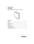
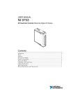
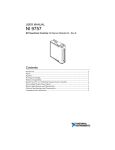
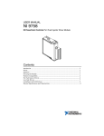
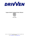
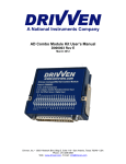
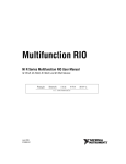
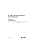
USER MANUAL
NI 9760
NI Powertrain Controls VR/Hall Sensor Module (Rev C)
Contents
Introduction ............................................................................................................2
Pinout ....................................................................................................................2
Powering the Module ...............................................................................................2
Platform Compatibility..............................................................................................3
Input Channels used for VR Sensor Inputs .................................................................3
Input Channels used for Hall-Effect Sensor Inputs ......................................................5
Physical Specifications and Characteristics ..................................................................5
Electrical Specifications and Characteristics ................................................................6
Introduction
The National Instruments 9760 offers a set of automotive style inputs to interface with standard automotive position sensors. It
provides six channels which may be software selected as a VR sensor or Hall-Effect sensor input.
Features
•
•
•
•
6 ch. channels software configured as VR sensor or Hall-effect senor inputs
o 600 kHz lowpass filter
o VR sensor inputs
§+/- 60V input range
§Adaptive or manually/programmable arming thresholds
o Hall-effect sensor or general purpose digital inputs
§Over/under voltage protection
§Optional software selectable pull-up resistor
External output for each channel according to software configuration
Sensor Power output: 5V @ 200mA
LabVIEW FPGA and LabVIEW Real Time VIs for quick integration with application.
Pinout
Figure 1. NI 9760 Pin Assignments
Powering the Module
The NI 9760 requires power from each for the following sources:
• The CompactRIO backplane male high density DSUB 15-pin (HD15) connector, which mates with the female HD15 connector
on the module. This power source provides a regulated 5 V and ground to various digital logic functions. The CompactRIO 5 V
source is active whenever the CompactRIO or R Series Expansion Chassis is properly powered. You can power the NI 9760 only
at the HD15 connector by plugging it into a CompactRIO or R Series Expansion Chassis. Do not connect the HD15 connector to
any other device.
2 | NI 9760 User Manual | © National Instruments
• If the 5V OUT lines or internal pull-up resistors are to be used for Hall-effect sensors, then the external DB-37 connector
pins labeled 5-30V IN (19) and GND (36) must be connected to an external supply of 5V to 30V. The module is reverse battery
protected to -30V.
The NI 9760 external power ground and CompactRIO backplane power ground are isolated and have no internal connection.
CAUTION The external battery supply input terminals are reverse voltage protected to -30 V. Connecting
the NI 9760 in reverse polarity at voltages greater than -30 V or forward polarity at greater than +30 V
will result in damage. This event is not covered by warranty.
Platform Compatibility
NI Powertrain Control modules require a hardware support system to function. You cannot use the modules independently or
interfaced with third-party devices at the backplane HD15 connector. NI Powertrain Control modules are compatible with the
following National Instruments platforms:
• CompactRIO, which consists of a CompactRIO controller, chassis, or integrated controller/chassis.
• NI PXI, which consists of any NI PXI chassis, NI PXI RT controller, and NI PXI-78xxR R Series FPGA card. The NI
Powertrain Control modules insert into an NI R Series expansion chassis. Connect an NI R Series expansion chassis to
the NI PXI FPGA card using a SHC68-68-RDIO cable.
• MXI-Express, Ethernet and EtherCAT expansion chassis.
Note NI Powertrain Control modules are not compatible with the National Instruments CompactDAQ
chassis.
Note NI Powertrain Control modules do not support Scan Interface mode.
Input Channels used for VR Sensor Inputs
The VR Hall module provides up to six identical VR sensor inputs. A Variable Reluctance (VR) sensor is a standard production
automotive speed sensor. It is an electromagnetic sensing device containing a winding of wire around a permanent magnetic
core. It relies on the movement of ferrous material (steel teeth) past the tip of the sensor to change the magnetic flux of the
sensor. This creates a voltage pulse across the leads of the sensor's wire coil. Figures 4 and 5 below show a typical VR signal
with respect to toothed wheels, as shown in figures 2 and 3. The VR signal will go positive as a tooth approaches the sensor
tip. The signal will then rapidly swing back through zero precisely at the center of the tooth. As the tooth moves away from the
sensor tip the voltage will continue in the negative direction and then return to zero.
Figure 2. Positive tooth trigger wheel
3 | NI 9760 User Manual | © National Instruments
Figure 3. Negative tooth trigger wheel
Figure 4. Correct signal polarity for VR input circuit
Figure 5. Incorrect signal polarity for VR input circuit
Each VR sensor input requires two connections. The VR Hall module pins labeled IN 1+ through IN 6+ are the positive sensor
inputs. The negative sensor inputs must be connected module pins labeled IN 1- through IN 6-. The polarity of the sensor
connection to the module is critical. The leads of the sensor should be connected such that the positive input of the VR circuit
sees the waveform shown in Figure 4. The waveform shown Figure 5 is incorrect, and the VR circuit will not properly respond to
this waveform. The rapid zero crossing of the VR signal must be in the negative direction.
The polarity of the physical tooth or gap on the trigger wheel will contribute to the polarity of the voltage pulse from the
sensor. Figure 2 demonstrates a positive physical tooth polarity and Figure 3 demonstrates a negative physical tooth polarity.
Assuming the lead polarity of a sensor remained the same, one of the configurations would generate the waveform shown in
Figure 4, while the other configuration would generate the waveform shown in Figure 5.
Triggers wheels are designed so that the physical center of each tooth or gap corresponds to a known angular position of the
wheel. This physical center of the tooth or gap always corresponds to the rapid zero-crossing of the generated voltage pulse.
The VR circuit is designed so that the rapid negative zero-crossing of the raw sensor signal corresponds to the rising edge of
a digital pulse sent to the RIO FPGA. The VR output signal to the FPGA will go TRUE at the rapid negative zero crossing of the
external VR pulse and remain TRUE until the external VR pulse rises above the arming threshold voltage. An example of this is
shown in Figure 6. Within LabVIEW FPGA the system designer can route this digital signal to the EPT CrankSig or CamSig input.
The signal can also be routed to any other speed measurement sub-VI.
4 | NI 9760 User Manual | © National Instruments
Figure 6. VR input pulse and resulting digital output from VR circuit
The absolute maximum VR pulse amplitude allowed by the circuit is +/- 60 volts. If the input signal exceeds this voltage,
damage may occur to the circuit. The amplitude should not exceed +/- 60 volts at maximum engine speed. The minimum VR
pulse amplitude that will generate a digital output by the VR circuit is +/-30 millivolts.
The VR circuit implements adaptive noise rejection features during continuous incoming VR pulses while in adaptive threshold
mode. In general, an adaptive arming threshold voltage is generated with each VR pulse at 33% of the previous pulse
amplitude. The next pulse must have an amplitude that exceeds the arming threshold in order for a digital output to be
generated at the rapid zero-crossing. If no arming event occurs for 85ms, the arming threshold is reset to 30 millivolts.
Alternately, a manually set arming threshold can be defined.
Given a constant gap between the sensor and the trigger teeth, the amplitude of a VR pulse is directly proportional to the
speed of the trigger wheel. For example, if the VR amplitude at 1000 RPM is +/-10 volts, then the amplitude at 2000 RPM will
be +/-20 volts. By using an oscilloscope to measure the VR amplitude at a low speed, this relationship can be used to determine
what the maximum amplitude will be at the maximum speed. If the maximum amplitude of +/- 60 volts will be exceeded at
maximum speed, then the sensor gap must be increased.
Input Channels used for Hall-Effect Sensor Inputs
The VR Hall module provides up to six identical hall-effect sensor input circuits. When using hall sensors, the ground of the
sensor should be connected to the IN - side of an input channel and one of the GND pins. If the hall sensor has an opencollector output, requiring a pull-up resistor at the collector, a pull-up resistor can be engaged through software. You must use
an external power supply to use the pull-up resistor.
The circuit's output to the RIO FPGA goes high when the input voltage is greater than the manually set threshold voltage. The
output goes low when the input is less than the manually set threshold voltage.
Physical Specifications and Characteristics
Weight
.....................................170g
Max. Altitude
.....................................2000m
Max. Ambient Temperature
.....................................60 °C
Operating Humidity
.....................................10 % to 90% RH, non-condensing
Pollution Degree
.....................................2
Ingress Protection
.....................................IP40
For indoor use only.
If you need to clean the module, wipe it with a dry towel.
5 | NI 9760 User Manual | © National Instruments
Electrical Specifications and Characteristics
External Power
Input Range
.....................................5 to 30 VDC Max
Reverse Polarity Protection
.....................................-30V
5V regulated output
Voltage Tolerance
.....................................5V 3%, Vsup 6V
Current
.....................................200mA
Short-circuit Protection
.....................................400mA
Inputs
Arming Threshold Digital-to-Analog Conversion Range
.....................................0 to 4.096
Arming Threshold Digital-to-Analog Resolution
.....................................10 bit
Arming Threshold Range(differential voltage at external pins)
.....................................0 to 2.97V
Lowpass Filter
.....................................600 kHz
Lag time from VR negativezero crossing event to Digital output rising edge
.....................................3us
Peak Voltage
.....................................+/- 60V
Outputs
Votage Standard
.....................................5V TTL
Reverse Polarity Protection
.....................................+/- 8mA
6 | NI 9760 User Manual | © National Instruments