1
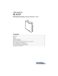
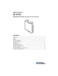
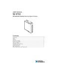
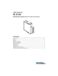
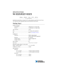
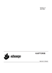
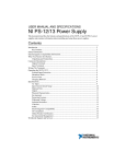
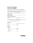
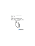
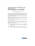
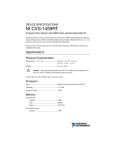
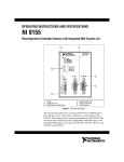
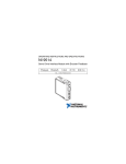
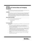
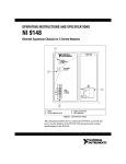
USER MANUAL NI 9758 NI Powertrain Controls Port Fuel Injector Driver Module Contents Introduction .............................................................................................................................. 2 Pinout........................................................................................................................................ 2 Hardware .................................................................................................................................. 3 Powering the Module................................................................................................................ 3 Platform Compatibility ............................................................................................................. 4 Port Fuel Injector Drivers ......................................................................................................... 4 Low-Side Drivers ..................................................................................................................... 7 Compliance and Certifications ................................................................................................. 9 Physical Specifications and Characteristics ............................................................................. 11 Introduction The National Instruments 9758 Port Fuel Injector (PFI) Driver Module includes a CompactRIO (cRIO) module for driving low and high impedance Port Fuel Injectors (PFI) and general purpose automotive solenoid valves and actuators. The NI 9758 includes a LabVIEW FPGA VI for controlling each driver channel. Each PFI channel is individually controlled for timing and duration. Each general purpose low-side solenoid driver is PWM controlled, capable of 0% to 100% duty cycle operation. Features: • 4-channel low or high impedance PFI driver • – Two phase current control – Turnable current level and duration for each phase – Optional recirculation at end of pulse – Open and short circuit detection and reporting with short circuit disable 4-channel general purpose low-side solenoid driver – 1.5 A continuous duty – PWM controlled – • • 0% to 100% duty cycle operation • 2 Hz to 10 kHz frequency operation • 500 ns resolution Open and short circuit detection and reporting with short circuit disable External power supply of 7 V to 32 V Pinout Figure 1. NI 9758 Pin Assignments 2 | ni.com | NI 9758 User Manual Hardware The NI 9758 provides four port fuel injector drivers and four general purpose low-side solenoid drivers in a NI CompactRIO module. Powering the Module The NI 9758 requires power from two different sources, a 15-pin D-SUB (HD15) connector and the external screw-terminal connector. The CompactRIO backplane male high density D-SUB 15-pin (HD15) connector mates with the module’s female HD15 connector. This power source provides a regulated 5 V and ground to various digital logic functions within the module. The CompactRIO 5 V source is active whenever the CompactRIO or R Series Expansion Chassis is properly powered. The NI 9758 should only be powered at the HD15 connector by plugging it into a CompactRIO or R Series Expansion Chassis. The NI9758 HD15 connector should not be connected to any other device. The external screw-terminal connector with the terminals labeled BATT (0) and GND (9) provide a second power source. Typical power sources will be from automotive 12 V or 24 V battery systems. The NI 9758 can accept power from 7 V to 32 V. The NI 9758 requires a maximum of 100 mA from an external power supply. When actuators and injectors are connected to and powered from the same power supply as the NI 9758, a battery or power supply capable of 10 A continuous output will be required under a full load. The NI 9758 requires both external power and power from the CompactRIO backplane. The high current path is directed through the BATT and GND terminals on the front of the NI 9758, not through the HD15 backplane connector. Note The NI 9758 will not be recognized by software without both power supplies active. The external battery supply input terminals are not reverse voltage polarity protected. Connecting power to the NI 9758 in reverse polarity will damage the NI 9758. This event is not covered by the warranty Caution NI 9758 Manual | © National Instruments | 3 Platform Compatibility NI Powertrain Control modules require a hardware support system to function. You cannot use the modules independently or interfaced with third-party devices at the backplane HD15 connector. NI Powertrain Control modules are compatible with the following National Instruments platforms: • CompactRIO, which consists of a CompactRIO controller, chassis, or integrated controller/chassis. • NI PXI, which consists of any NI PXI chassis, NI PXI RT controller, and NI PXI-78xxR R Series FPGA card. The NI Powertrain Control modules insert into an NI R Series expansion chassis. Connect an NI R Series expansion chassis to the NI PXI FPGA card using a SHC68-68-RDIO cable. NI Powertrain Control modules are not compatible with the National Instruments CompactDAQ chassis. Note You can use NI Powertrain Control modules with NI cRIO-911x, NI cRIO-907x, and NI R Series Expansion systems under the following conditions: • Leave one empty chassis slot between NI Powertrain Control modules and other NI modules. • Maintain an ambient system operating temperature of 0 °C to 45 °C. Typical specifications of National Instruments modules might not apply when used in a system with NI Powertrain Control modules. Note National Instruments guarantees warranted specifications for all National Instruments modules except thermocouple modules when used in a system with NI Powertrain Control modules. Note National Instruments recommends the NI 9214 for thermocouple measurements in CompactRIO systems using NI Powertrain Control modules. Note NI Powertrain Control modules do not support Scan Interface mode, auto-detection, or ID mode. Note Port Fuel Injector Drivers Each PFI driver channel is capable of driving low or high impedance port fuel injectors. Driving Low Impedance Injectors Low impedance injectors will have approximately 2 Ω resistance across the solenoid which allows a higher current through the solenoid to enable faster valve opening times. High current is not needed for the entire duration of the injection event in order to keep the valve open. The initial current level is referred to as the peak current and the current level for the remaining injection duration is referred to as the hold current. The standard configuration for the PFI drivers is a peak current of 4 A and a hold current of 1 A. 4 | ni.com | NI 9758 User Manual The NI 9758 has two phases of current control. The maximum phase current is 4 A. Control can be set to transition from the first to the second phase after a set time or immediately when the first current level is reached. To drive low impedance injectors, set the first phase peak current to 4 A and the second phase hold current to 1 A. If for the entire duration of the injection event, neither peak nor hold current levels are reached, then an open circuit will be reported for the channel. It is possible that an open condition may be falsely reported under certain conditions, even though a fuel injector is properly connected. Examples of this include very low battery voltage, poor connections which introduce added resistance, or total injection duration, which is less than the requested peak time and the peak current is never reached. Each PFI driver channel is protected from accidental short circuit to battery. At the beginning of each injection event, the current rise rate is monitored in order to detect a short circuit. If the current rises faster than expected for a typical port fuel injector solenoid, then a short circuit error flag will be reported for that channel and the channel will be disabled until software clears the error flag. Short circuit detection is also performed continuously at a later time within each injection event. The short circuit error flag for each channel will not be cleared while an injection event is being commanded for that channel. It is strongly recommended that the user not continually clear the short circuit error flags, as this may lead to driver circuit damage in the event of an actual short circuit. Even though the short circuit detection and disable feature is present, it is strongly recommended that the wiring harness include a 5 A automotive fuse for four low impedance injectors as shown below. Figure 2 is a representation of a typical peak/hold current trace if one of the injector leads were monitored with a current probe and oscilloscope. Figure 2. Peak/Hold Current Profile NI 9758 Manual | © National Instruments | 5 Driving High Impedance Injectors High impedance injectors may be used with the PFI driver circuits without any hardware or software configuration changes. High impedance injectors will have approximately 12 Ω resistance across the solenoid. Typically, less than 1 A is required to open and hold the solenoid valve. High impedance injectors require a single current phase. Set the duration of the first phase to zero to keep control of the phase during the injection event. The open circuit flag should be ignored when driving high impedance injectors because the hold current level of 1 A may never be reached, thus reporting a false open circuit. Short circuit detection operates identically to that of low impedance injector control and the channel will be disabled if a short is detected, until the error flag is cleared in software. Even though the short circuit detection and disable feature is present, it is strongly recommended that the wiring harness include a 5 A automotive fuse for four high impedance injectors. Figure 3. Hold Current Reached and Controlled Figure 4. Hold Current Never Reached Do not attempt to drive low impedance injectors with the general purpose low-side switch drivers. The low-side drivers are only rated for 1.2 A continuous. The resulting higher current levels could damage the low-side drivers. Caution 6 | ni.com | NI 9758 User Manual Figure 5. Connecting Port Fuel Injectors to the Driver Module Note A CompactRIO controller may be powered by the same power source or by an isolated power source. If the Compact RIO controller is powered by the same battery used for cranking the engine, then it is possible that the battery voltage will drop below 9 V during cranking, causing the CompactRIO controller to reset. This can be prevented by using a small backup battery and a diode pack for the CompactRIO controller. Visit ni.com/info and enter Info Code PFI for recommended parts and connections for the NI 9758. Low-Side Drivers The low-side drivers are capable of driving a wide variety of automotive relays and actuators. Examples of actuators include EGR valves, turbo wastegate valves, fuel pressure regulators, or any single-solenoid-actuator which draws less than 1.2 A at the highest expected battery voltage. Caution Do not attempt to drive low impedance injectors or solenoids with the general purpose low-side drivers. The low-side drivers are only rated for 1.2 A continuous. Higher current levels could damage the low-side drivers. Each channel is independently controlled within the module via pulse-width modulation (PWM). PWM duty cycle from 0% to 100% is possible. Software on the RIO FPGA device communicates several parameters for each channel to operate. Those parameters are Enable, Period and PulseWidth. All parameters are communicated serially at 200 µs intervals. Each PWM controller utilizes a 20-bit timer operating at 2 MHz. This provides a resolution of 500 ns and a minimum PWM frequency of 2 Hz. Since 0% and 100% duty cycles are possible, relays and actuators may be controlled in continuous on or off states. NI 9758 Manual | © National Instruments | 7 Each low-side driver channel automatically tests for open circuit conditions. When the low-side switch is commanded open, the circuit is tested for an open condition. Upon detection of an open circuit, an open circuit error flag will be reported. The error flag may be cleared by software. Driver circuit operation is not affected by an open circuit error flag that is left asserted. Each low-side driver channel automatically protects itself from an accidental short circuit to battery. When the low-side switch is commanded closed, the circuit is tested for a short. Upon detection of a short, a short circuit error flag will be reported for the channel and the channel will be disabled until software clears the error flag. The short circuit error flag for each channel will not be cleared while the switch is being commanded closed. It is strongly recommended that the user not continually clear the short circuit error flags, as this may lead to driver circuit damage in the event of an actual short circuit. Even though the short circuit detection and disable feature is present, it is strongly recommended that the wiring harness include a 5 A automotive fuse for four solenoids. Figure 6. Connecting General Purpose Solenoids to the Low-Side Driver Channels A CompactRIO controller may be powered by the same power source or by an isolated power source. If the CompactRIO controller is powered by the same battery used for cranking the engine, then it is possible that the battery voltage will drop below 9 V during cranking, causing the CompactRIO controller to reset. This can be prevented by using a small backup battery and a diode pack for the CompactRIO controller. Note 8 | ni.com | NI 9758 User Manual Compliance and Certifications Safety This product meets the requirements of the following standards of safety for electrical equipment for measurement, control, and laboratory use: • IEC 61010-1, EN 61010-1 • UL 61010-1, CSA 61010-1 Electromagnetic Compatibility This product meets the requirements of the following EMC standards for electrical equipment for measurement, control, and laboratory use: • EN 61326-1 (IEC 61326-1): Class A emissions; Industrial immunity • EN 55011 (CISPR 11): Group 1, Class A emissions • AS/NZS CISPR 11: Group 1, Class A emissions • FCC 47 CFR Part 15B: Class A emissions • ICES-001: Class A emissions Caution When operating this product, use shielded cables and accessories. CE Compliance This product meets the essential requirements of applicable European Directives as follows: • 2006/95/EC; Low-Voltage Directive (safety) • 2004/108/EC; Electromagnetic Compatibility Directive (EMC) NI 9758 Manual | © National Instruments | 9 Environmental Management NI is committed to designing and manufacturing products in an environmentally responsible manner. NI recognizes that eliminating certain hazardous substances from our products is beneficial to the environment and to NI customers. For additional environmental information, refer to the Minimize Our Environmental Impact web page at ni.com/environment. This page contains the environmental regulations and directives with which NI complies, as well as other environmental information not included in this document. Waste Electrical and Electronic Equipment (WEEE) At the end of the product life cycle, all products must be sent to a WEEE recycling center. For more information about WEEE recycling centers, National Instruments WEEE initiatives, and compliance with WEEE Directive 2002/96/EC on Waste and Electronic Equipment, visit ni.com/environment/ weee. EU Customers Battery Replacement and Disposal Cd/Hg/Pb Battery Directive Battery Directive This device contains a long-life coin cell battery. If you need to replace it, use the Return Material Authorization (RMA) process or contact an authorized National Instruments service representative. For more information about compliance with the EU Battery Directive 2006/66/EC about Batteries and Accumulators and Waste Batteries and Accumulators, visit ni.com/ environment/batterydirective. ⬉ᄤֵᙃѻક∵ᶧࠊㅵ⧚ࡲ⊩ ˄Ё RoHS˅ Ёᅶ᠋ National Instruments ヺড়Ё⬉ᄤֵᙃѻકЁ䰤ࠊՓ⫼ᶤѯ᳝ᆇ⠽䋼ᣛҸ (RoHS)DŽ݇Ѣ National Instruments Ё RoHS ড়㾘ᗻֵᙃˈ䇋ⱏᔩ ni.com/ environment/rohs_chinaDŽ (For information about China RoHS compliance, go to ni.com/environment/rohs_china.) Ferrite Requirement for EMC Compliance Install a clamp-on ferrite bead onto both the power supply cable and the signal cable. Power to the module must be off when adding ferrites. Ferrites must be connected to the power cable and the signal cable as close to the module as possible. Placing the ferrite elsewhere on the cable noticeably impairs its effectiveness. Determine the clamp-on ferrite beads to install based on your application. Use the following ferrites or other similar ferrites: • Power cable: Laird 28A0592-0A2 • Signal cable: TDK Cat3035 (2 total) 10 | ni.com | NI 9758 User Manual Physical Specifications and Characteristics Weight............................................................... 145 g Screw-terminal wiring ...................................... 1.02 mm in diameter (18 AWG) or larger Maximum Altitude ........................................... 2000 m Operating Temperature ..................................... -40 °C to 70 °C Maximum Ambient Temperature ..................... 60 ºC Operating Humidity .......................................... 10% to 90% RH, noncondensing Pollution Degree ............................................... 2 Ingress Protection ............................................. IP30 For indoor use only. If you need to clean the module, wipe it with a dry towel. Safety Guidelines Do not operate the NI 9758 PFI Driver in a manner not specified in these operating instructions. Product misuse can result in a hazard. You can compromise the safety protection built into the product if the product is damaged in any way. If the product is damaged, return it to National Instruments for repair. Caution NI 9758 Manual | © National Instruments | 11 Refer to the NI Trademarks and Logo Guidelines at ni.com/trademarks for more information on National Instruments trademarks. Other product and company names mentioned herein are trademarks or trade names of their respective companies. For patents covering National Instruments products/technology, refer to the appropriate location: Help»Patents in your software, the patents.txt file on your media, or the National Instruments Patents Notice at ni.com/patents. You can find information about end-user license agreements (EULAs) and third-party legal notices in the readme file for your NI product. Refer to the Export Compliance Information at ni.com/legal/export-compliance for the National Instruments global trade compliance policy and how to obtain relevant HTS codes, ECCNs, and other import/export data. © 2013 National Instruments. All rights reserved. 376107A-01 Sep13