1
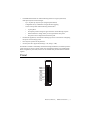
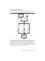
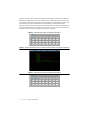
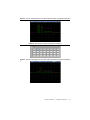
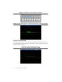
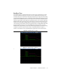
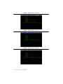
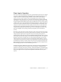
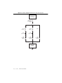
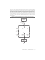
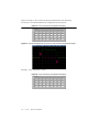
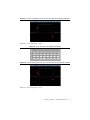
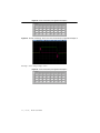
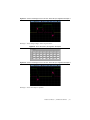
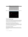
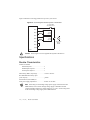
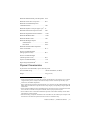
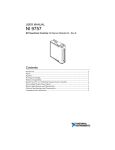
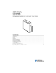
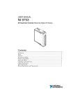
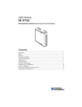
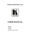
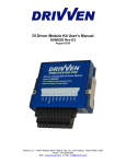
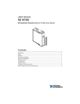
USER MANUAL NI 9751 NI Powertrain Controls Direct Injector Driver Module Contents Safety Guidelines...................................................................................................................... 2 Introduction .............................................................................................................................. 2 Pinout........................................................................................................................................ 3 Hardware .................................................................................................................................. 4 Powering the Module................................................................................................................ 4 Platform Compatibility ............................................................................................................. 6 Internal Boost Power Supply .................................................................................................... 7 Direct Injector Drivers.............................................................................................................. 10 Connecting Injectors to the Module ......................................................................................... 25 Specifications............................................................................................................................ 26 Where to Go for Support .......................................................................................................... 29 Safety Guidelines The NI 9751 normally operates at voltages up to 190 V. Take extreme care to protect against shock. Even when the NI 9751 is completely powered off, allow approximately three minutes for the internal high voltage to dissipate. Do not touch any of the module screw terminals or injector terminals while the NI 9751 is powered on. High Voltage Do not operate this module in a manner not specified in these operating instructions. Product misuse can result in a hazard. You can compromise the safety protection built into the product if the product is damaged in any way. If the product is damaged, return it to National Instruments for repair. Caution The fuse illustrated in Figures 32 and 33 is user-supplied and required in all instances. Caution Introduction The NI 9751 Direct Injector (DI) Driver Module includes the following components: • CompactRIO (cRIO) module with the following components for driving a variety of diesel and gasoline DIs, including many piezo actuated injectors: – 3-channel solenoid injector drivers – 2-channel piezo injector drivers (in piezo mode) – Up to 120 V internal boost power supply in solenoid mode – Up to 190 V internal boost power supply in piezo mode – Up to 40 A peak current drive – 7 V to 32 V battery – Optional external input for high voltage supply (up to 190 V) • – 2 | Internal boost supply automatically shuts down when external high voltage applied is greater than 24 V Circuit protection and diagnostics features, including: • Protected against INJ± short to battery/high voltage • Protected against INJ± short to GND • Internal power supply overload protection • Internal power supply over-charge protection • Module temperature protection • Open circuit detection • Fault flags reported for all above conditions ni.com | NI 9751 User Manual • LabVIEW FPGA and RT VIs with the following features for engine-synchronous, multi-pulse injection control strategies: – Up to 16 pulses per injection cycle (Engine Speed Limited) – Configurable for any combination of angle and time triggering – Current control profile with the following characteristics: • Up to 8 phases • Each phase provides settings for upper and lower current dithering setpoints • Duration and drive voltage (battery or boost) specified for each phase • First phase can be configured to end after first peak • DI Calibrator application, which assists with firing injectors on a test bench for configuring the injector current/voltage profile • Piezo injector operation for unipolar drive • Inverted piezo drive supported (Discharge = ON, Charge = OFF) Each DI driver channel is individually controlled for timing and duration, but channel operation cannot overlap. The NI 9751 cannot control piezo and solenoid actuator types simultaneously. When configured for piezo mode, channel 3 is not available and you must short the terminals together. Pinout BATT INJ1– INJ1+ INJ2– INJ2+ INJ3– INJ3+ EXT PWR GND GND 0 1 2 3 4 5 6 7 8 9 NI 9751 User Manual | © National Instruments | 3 Hardware The NI 9751 provides three channels for driving unipolar solenoid and piezo injectors in a National Instruments cRIO module. Use the included internal boost power supply to provide short phases of boosted voltages for higher current operation. Powering the Module The NI 9751 requires power from each of the following sources: • The CompactRIO backplane male high density 15-pin DSUB (HD15) connector, which mates with the female HD15 connector on the module. This power source provides a regulated 5 V and ground to various digital logic functions. The CompactRIO 5 V source is active whenever the CompactRIO or R Series Expansion Chassis is properly powered. You can power the NI 9757 only at the HD15 connector by plugging it into a CompactRIO or R Series Expansion Chassis. Do not connect the HD15 connector to any other device. • The external screw terminal connector block, the terminals of which are labeled BATT (0) and GND (9). A typical power source is an automotive 12 VDC or 24 VDC battery system, but the NI 9751 can accept power from a range of 7 VDC to 32 VDC. Caution You must use a UL-listed power supply with the NI 9751. With the internal boost power supply and injector outputs disabled, the NI 9751 requires up to 100 mA from the external supply. The following formula calculates the total power required to operate the module and drive injectors: HVT arg et × IP × Tip RPMmax × Nchan × Npulse Power = ----------------------------------------------------- + BattV × Ih × ( DurAve – Tip ) × ------------------------------------------------------------------------ 2 × 0.70 2 × 60 Where: Ip (A) = Peak current Ih (A) = Hold current HVTarget (V) = High Voltage Target from internal boost supply BattV (V) = Battery voltage supplied to BATT(0) Tip (sec) = Time of peak current phase DurAve (sec) = Average duration of all injection pulses within an engine cycle RPMmax (RPM) = Maximum engine speed in RPM Nchan = Number of channels used Npulse = Number of injection pulses per engine cycle This formula assumes a 4-stroke engine cycle. For 2-stroke engines, multiply the result by 2. 4 | ni.com | NI 9751 User Manual Table 1. Example Power Calculation Parameter Value Ip 25 A Ih 15 A HVTarget 75 V BattV 13.8 V Tip 0.000100 sec DurAve 0.000800 sec RPMmax 4500 RPM Nchan 3 Npulse 2 Power 65 W Continuous Current 4.5 A A 100 W power supply is sufficient for most applications. Power requirements might peak up to 150 W for more demanding applications. The external battery ground is isolated, within the module, from the CompactRIO 5 V supply ground. You can externally connect the external battery ground and the CompactRIO ground. Note Both power supplies must be active for software to recognize the module. The external battery supply input terminals are not protected against reverse-voltage polarity. Connecting power to the module in reverse polarity will damage the module. This event is not covered by warranty. Caution The NI 9751 includes an optional power input to the external screw terminal connector block labeled EXT PWR (7). The ground reference for EXT PWR (7) must be the same ground as GND (9). This power input can range from 24 V to 190 V and is optionally used to provide the boost voltage in place of the internal boost supply. Because the internal boost power supply is a significant contributor to the internal module heat generation, this external power input might be necessary if the injector drive requirements, in combination with maximum engine speeds, cause the internal module temperature to exceed the limit. When a voltage greater than 24 V is applied to the EXT PWR (7) terminal, the internal boost power supply automatically shuts off, even if it is enabled via software. Even when EXT PWR (7) is connected to an external high voltage power source, BATT (0) must still be connected to 7 V to 32 V in order for the module to be properly powered for general functions. In most applications the EXT PWR (7) terminal is not necessary and should be left unconnected. NI 9751 User Manual | © National Instruments | 5 Platform Compatibility NI Powertrain Control modules require a hardware support system to function. You cannot use the modules independently or interfaced with third-party devices at the backplane HD15 connector. NI Powertrain Control modules are compatible with the following National Instruments platforms: • CompactRIO, which consists of a CompactRIO controller, chassis, or integrated controller/chassis. • NI PXI, which consists of any NI PXI chassis, NI PXI RT controller, and NI PXI-78xxR R Series FPGA card. The NI Powertrain Control modules insert into an NI R Series expansion chassis. Connect an NI R Series expansion chassis to the NI PXI FPGA card using a SHC68-68-RDIO cable. NI Powertrain Control modules are not compatible with the National Instruments CompactDAQ chassis. Note You can use NI Powertrain Control modules with NI cRIO-911x, NI cRIO-907x, and NI R Series Expansion systems under the following conditions: • Leave one empty chassis slot between NI Powertrain Control modules and other NI modules. • Maintain an ambient system operating temperature of 0 °C to 45 °C. Note Typical specifications of National Instruments modules might not apply when used in a system with NI Powertrain Control modules. National Instruments guarantees warranted specifications for all National Instruments modules except thermocouple modules when used in a system with NI Powertrain Control modules. Note National Instruments recommends the NI 9214 for thermocouple measurements in CompactRIO systems using NI Powertrain Control modules. Note Note NI Powertrain Control modules do not support Scan Interface mode, auto-detection, or ID mode. 6 | ni.com | NI 9751 User Manual Internal Boost Power Supply The NI 9751 contains an internal boost power supply that can maintain a voltage level from battery voltage up to 190 V. You can use software to enable or disable boost power supply at any time. The internal booster power supply is disabled automatically whenever critical faults occur and can only be enabled by clearing the faults. Internal capacitors store the high voltage, which is used to drive the high-voltage phases of the injector current profile. The NI 9751 normally operates at voltages up to 190 V. Take extreme care to protect against shock. Even when the NI 9751 is completely powered off, allow approximately three minutes for the internal high voltage to dissipate. Do not touch any of the module screw terminals or injector terminals while the NI 9751 is powered on. High Voltage Internal Boost Power Supply Performance The following critical factors determine how well the internal boost power supply will perform for a particular injector solenoid application: • Injector solenoid resistance • Injector solenoid inductance • Peak current required to open the injector valve • Working voltage requirement (HVTarget) • Frequency of injection events • Injector solenoid back-boost time (BackBoostTime) Injector Solenoid Resistance Typical common rail diesel injector solenoids will have a resistance of 1 Ω or less. This resistance wastes, as heat, a portion of the energy supplied to the solenoid and affects the maximum current achieved in the coil, which depends on the drive voltage applied. In general, lower solenoid resistances are better for common rail solenoid injector applications. Injector Solenoid Inductance Typical common rail injector solenoids have an inductance of 1 mH or less. Inductance acts to resist current change through the coil. As inductance increases, more time is required to achieve the required peak current level, given a constant drive voltage. When you use the internal high voltage to drive current, energy transfers from the internal high voltage capacitance to the injector solenoid. Longer drive times deplete energy from the internal high voltage capacitance. The internal boost supply works harder to maintain the high voltage target. Inductance is proportional to the magnetic force generated for opening the injector valve. Peak Current Requirement Higher peak-currents require more energy from the internal boost power supply because the internally stored high voltage depletes at a higher rate. NI 9751 User Manual | © National Instruments | 7 Working Voltage Requirement The internal boost power supply can maintain a higher working voltage to drive the peak current level in a shorter amount of time and provide quicker valve opening times and more predictable fuel injection quantities over a given injection duration. The boost power supplies operate less efficiently at higher voltages. The power supply must work harder to maintain a higher working voltage. Typical times to reach 20 A in common-rail diesel injectors are on the order of 30 to 100 μs, with a working voltage of 100 V. Frequency of Injection Events The frequency of injection events is directly proportional to the work the power supply requires to maintain the working voltage. Injector Back-Boost You can obtain a significant and useful back-boost charge from the injector solenoid at the end of each injection event. This back-boost from the solenoid depends on the hold-current level during the injection event and the working voltage of the boost power supply. If you correctly configure the current profile, a small back-boost on the order of 5 V occurs to the power supply, which reduces the work required to maintain the working voltage. You might incorrectly configure the module to use very little of the high voltage supply for driving the peak current while also setting a high hold-current level. This configuration can lead to back-boosting the power supply over the required working voltage. Use the internal high voltage supply to prevent this from happening. If the working voltage exceeds 190 V, a fault occurs and shut down proceeds automatically. Power Supply Faults and Protections The following critical faults related to the operation of the internal power supply might cause all operations of the module to shut down automatically. Two or more of these faults might occur under certain conditions. For example, the power supply might be loaded such that the board temperature reaches its limit before the overload integrator limit is reached. You can re-enable the internal boost power supply and injection control by manually clearing the faults with software. Power Supply Charge Fault (PSCharge) If the power supply is actively attempting to recharge and detects that the voltage is not rising, the charge fault is set. This fault most likely occurs when an internal problem, such as a capacitor failure, exists with the module. Power Supply Overload Fault (PSOverLoad) The NI 9751 maintains an integrator of power supply usage. An internal counter increments with each power supply voltage boost and decrements according to a fixed time interval. If the integrator winds up to 148,480 counts, an overload fault is set. This fault indicates that the module temperature will soon rise beyond the maximum operating temperature unless stopped. The module temperature fault might trip before the overload fault, depending on the actual conditions. 8 | ni.com | NI 9751 User Manual Module Temperature Fault (ModuleTemperature) Due to the C Series module housing design, there is limited ability for heat to escape. The primary source of heat within the NI 9751 is the internal boost power supply. If the internal module temperature rises above approximately 80 °C, the module temperature fault is set. High Voltage Limit Fault (HighVoltageLimit) If the charge on the internal power supply exceeds 190 V, the high voltage limit fault sets. This fault can occur due to excessive injector solenoid back-boosting. Excessive solenoid back-boosting can be caused by driving solenoids with very high inductance while not using the boost supply. Internal Boost Power Supply Benchmarks Table 2 describes bench test results that demonstrate power supply capability. Table 2. Bench Test Results Test 1 (Solenoid) Test 2 (Solenoid) Test 3 (Piezo) 13.8 13.8 13.8 HVTarget (V) 75 75 190 PeakCurrent (A) 27 27 8 PeakTime (ms) 0.18 0.18 s N/A HoldCurrent (A) 15 15 N/A 0.20 0.20 N/A Number of injectors operated 3 3 2 Number of fuel pulses per cycle 1 5 1 Simulated engine speed (RPM) 5,000 2,000 7,200 Length of test (min) 10 10 480 Ambient temperature (°C) 25 25 25 Final module temperature (°C) 50 75 72 Temperature stabilized? Y N Y Test Condition External Battery Voltage (V) BackBoostTime (ms) Injector under test Bosch P/N 0445 110 072 Mercedes Benz P/N 611 070 09 87 Bosch P/N 0445 115 027 With air flow over the NI 9751, you can extend the duration of operation at heavy loads. NI 9751 User Manual | © National Instruments | 9 The internal power supply requires approximately 10 ms to charge from 12 V to 100 V, and approximately 20 ms to charge from 12 V to 150 V. This charge-up process occurs immediately when enabling the power supply. With the power supply enabled, the requested working voltage is maintained while injection events are not commanded. Depending on the working voltage, you might hear a slow frequency of faint clicks from the module. This is normal noise from the power supply. The DI Calibrator application can assist you in determining the proper current and voltage profile settings to meet your injector solenoid requirements. NI will assist you with determining calibration parameters for your injectors at no cost if NI can reuse the calibration data for future projects. This does not include fuel flow measurements. You must provide NI with current profile information and a test solenoid or injector. When the internal supply is disabled, the high voltage bleeds down to battery voltage from 190 V in approximately 3 minutes. Connecting an External Power Supply to EXT PWR (7) Connect an optional high voltage external power supply to the EXT PWR (7) terminal if the internal boost power supply is overheating or cannot keep up with the injection requirements. Inside the module, the external high voltage supply connects to the same internal capacitance as the internal boost supply. Ensure that you make a permanent connection before you power the external power supply. When an external high voltage supply greater than 24 V is detected, the internal boost supply automatically shuts down. The BATT (0) terminal must still be connected and powered by 7 V to 32 V even when you use an external high voltage supply connected to the EXT PWR (7) terminal. A high voltage external power supply is not necessary for most applications. If the internal boost power supply cannot meet the demands of the application, consider using only two of the three available channels instead of all three before using an external high voltage power supply. For example, consider using three DI driver modules for a six-cylinder engine to lighten the load on each module. Suggested External High Voltage Supplies TDK Lambda Genesys 100-15 Direct Injector Drivers Injector Driver Circuit Description The NI 9751 contains three solenoid DI drivers and can drive two Piezo injectors. The driver channels share some circuitry, so injection events cannot overlap among channels within the same module. If injection events with different injectors must overlap, you must use multiple modules. The NI 9751 contain a high-voltage circuit and battery-voltage circuit that drive current to the injector load. Figure 1 shows the high-voltage and battery-voltage drive circuits in the simplified schematics for operating various types of injectors. 10 | ni.com | NI 9751 User Manual Solenoid Injector Operation Figure 1 shows a representative simplified schematic that drives three solenoid injectors. Figure 1. NI 9751 Simplified Schematic for Solenoid Injectors. Internal Boost Power Supply High-Side, High-Voltage Switch High-Side, Low-Voltage Switch + Injector 1 + Injector 2 – CH1 Low-Side Switch BattV + Injector 3 – CH2 Low-Side Switch – CH3 Low-Side Switch Current Sense & Comparator Circuitry You can programmatically specify up to eight sequential drive phases within each solenoid injection command pulse by using an 8-element IPhaseArray. Each phase is implemented sequentially and can specify upper and lower current dithering setpoints, phase duration, and high-voltage or battery-voltage drive circuit. Use the high-voltage drive circuit only when necessary to conserve internal boost power supply energy and not overload it. A dual comparator feedback circuit for upper and lower dithering thresholds controls the solenoid current. Other current- and voltage- sensing circuits are used for fault detection. NI 9751 User Manual | © National Instruments | 11 Figures 2 through 9, show oscilloscope images that demonstrate waveforms for four different IPhaseArray configurations. Three of the examples show common direct injection waveforms. The fourth waveform is not typical, but shows the flexibility of the IPhaseArray interface. The total duration of the injection command is not determined by the total durations of the IPhaseArray elements, but by the Boolean command delivered to the DI Driver FPGA Express VI. If the Duration parameter of an IPhaseArray element is set to 0, the current levels for that element are carried out for the remainder of the injection command. Figure 2. Solenoid IPhaseArray Configuration Example 1 Figure 3. Current and Voltage Traces from Solenoid IPhaseArray Configuration Example 1 Figure 4. Solenoid IPhaseArray Configuration Example 2 12 | ni.com | NI 9751 User Manual Figure 5. Current and Voltage Traces from Solenoid IPhaseArray Configuration Example 2 Figure 6. Solenoid IPhaseArray Configuration Example 3 Figure 7. Current and Voltage Traces from Solenoid IPhaseArray Configuration Example 3 NI 9751 User Manual | © National Instruments | 13 Figure 8. Solenoid IPhaseArray Configuration Example 4 Figure 9. Current and Voltage Traces from Solenoid IPhaseArray Configuration Example 4 Phase1FirstPeakEnable The Phase1FirstPeakEnable is a Boolean control that transfers operation from the first phase to the second phase upon reaching the first current peak that corresponds to the first phase IUpper threshold, as shown in Figure 10. Figure 10. Current and Voltage Traces from Phase1FirstPeakEnable=TRUE Operating Mode 14 | ni.com | NI 9751 User Manual BackBoostTime The BackBoostTime is a global parameter that is critical for proper solenoid injector control. This time period directly follows the end of the injection command duration and allows the back-emf of the injector solenoid to be directed to the internal power supply for back-boosting the internal high voltage power supply. The BackBoostTime brings the injector solenoid current quickly to zero. If BackBoostTime is set to zero, injector current recirculates through the injector until the energy dissipates, which might cause unpredictable injector valve closing. Calibrate the BackBoostTime long enough for the energy within the injector solenoid to fully discharge to the internal boost power supply. If BackBoostTime is greater than zero, but too short, the injector current bumps up and recirculates until the energy fully dissipates. Extend BackBoostTime until the scope solenoid current trace can no longer display the current recirculation. A typical BackBoostTime is approximately 0.2 ms. Injectors with higher inductance provide more energy to dissipate at the end of injection and thus require a longer BackBoostTime. Figures 11 through 15 show different values for BackBoostTime applied to the same solenoid injector. Figure 11. BackBoostTime = 0.0 ms Figure 12. BackBoostTime = 0.025 ms NI 9751 User Manual | © National Instruments | 15 Figure 13. BackBoostTime = 0.050 ms Figure 14. BackBoostTime = 0.100 ms Figure 15. BackBoostTime = 0.150 ms 16 | ni.com | NI 9751 User Manual Piezo Injector Operation The NI 9751 can of drive unipolar piezo injectors. Unipolar means the piezo injector is charged to a positive voltage and discharged to ground. Bipolar drive means the piezo injector can be charged to a positive or negative voltage. Channels 1 and 2 are viable for driving piezo injectors. You must connect Channel 3 with a shorting jumper between the Inj+ and Injterminals.Electrically, piezo injectors are a capacitive load, instead of an inductive load from solenoid injectors. Solenoid injectors require current to be driven through the solenoid to create the proper magnetic field within the injector body to mechanically open a valve. Piezo injectors contain a stack of piezo crystal elements that respond mechanically to a voltage applied across the stack. The two pins of the piezo injector are connected internally across the stack. As the voltage across the stack increases, the stack expands, and exerts a force to open a fluid valve. The piezo injectors respond more quickly than a solenoid operated injector. It is difficult to estimate the fuel quantity injected while the injector valve is opening. By achieving a shorter time from energizing to valve opening, the fuel injection quantity can be metered more precisely. Electrically, a piezo stack is like a capacitor because it requires current in one direction to charge up to a specified voltage, and current in the opposite direction to discharge. The typical charge voltage required for piezo injectors ranges from 100 V to 200 V. Most piezo injectors in production today require up to 165 V, but vary depending on desired fuel rail pressure. A piezo stack charges up to a specified voltage at a rate that does not damage the stack. The charge and discharge current must be controlled. You can control charge and discharge current with an inductive element in series with the piezo stack and treating the element similar to a current control inductive load. The NI 9751 provides a special piezo mode of operation that utilizes the same IPhaseArray interface to control current to the piezo stack for charge and discharge rates. When charging the piezo stack, the final charge is a few volts less than the HVTarget setpoint. When discharging the piezo stack, the final discharge state is 0 V. The IPhaseArray behaves differently in piezo mode. The first four elements of the IPhaseArray are used for charge and the last four elements are used for discharge. The BackBoostTime parameter is not used for piezo injector operation. The DriveSrc Boolean for each IPhaseArray element is not applicable for piezo injector operation because the high-voltage driver circuit is always used. Figure 16 shows a representative simplified schematic that drives two piezo injectors. NI 9751 User Manual | © National Instruments | 17 Figure 16. DI Driver Simplified Schematic for Two Piezo Injectors Internal Boost Power Supply High-Side, High-Voltage Switch + + 47 µH Inductor 47 µH Inductor Piezo Injector 1 Piezo Injector 2 – CH1 Low-Side Switch Short – CH2 Low-Side Switch Current Sense & Comparator Circuitry 18 | ni.com | NI 9751 User Manual + – CH3 Low-Side Switch The NI 9751 can also operate inverted charge scheme piezo injectors. The PiezoInvert Boolean determines the inverted piezo mode. The injector valve closes when the stack is charged and the valve opens when the stack is discharged. Channel 1 can operate only a single piezo injector when operated in inverted mode.You must leave Channel 2 disconnected and connect Channel 3 with a shorting jumper between the Inj+ and Inj- terminals. When you enable PiezoInvert mode, the first four IPhaseArray elements are used for discharge and the last four elements are used for charge. Figure 17 shows a representative simplified schematic that drives a single piezo injector in inverted mode. Figure 17. DI Driver Simplified Schematic for a Single Inverted Piezo Injector Internal Boost Power Supply High-Side, High-Voltage Switch + 47 µH Inductor + + Open Short Piezo Injector 1 – CH1 Low-Side Switch – CH2 Low-Side Switch – CH3 Low-Side Switch Current Sense & Comparator Circuitry NI 9751 User Manual | © National Instruments | 19 Figures 18 through 31, show oscilloscope images that demonstrate current and voltage waveforms for seven different IPhaseArray configurations for piezo injectors. Figure 18. Piezo IPhaseArray Configuration Example 1 Figure 19. Current and Voltage Traces From Piezo IPhaseArray Configuration Example 1 HVTarget = 150 V. Charge time = 148 μs. Figure 20. Piezo IPhaseArray Configuration Example 2 20 | ni.com | NI 9751 User Manual Figure 21. Current and Voltage Traces from Piezo IPhaseArray Configuration Example 2 HVTarget = 150 V. Charge time = 124 μs. Figure 22. Piezo IPhaseArray Configuration Example 3 Figure 23. Current and Voltage Traces from Piezo IPhaseArray Configuration example 3 HVTarget = 150 V. Charge time = 188 μs. NI 9751 User Manual | © National Instruments | 21 Figure 24. Piezo IPhaseArray Configuration Example 4 Figure 25. Current and Voltage Traces from Piezo IPhaseArray Configuration Example 4 HVTarget = 150 V. Charge voltage = 100 V. Figure 26. Piezo IPhaseArray Configuration Example 5 22 | ni.com | NI 9751 User Manual Figure 27. Current and Voltage Traces from Piezo IPhaseArray Configuration Example 5 HVTarget = 150 V. Charge voltage = 100 V step, then 150 V. Figure 28. Piezo IPhaseArray Configuration Example 6 Figure 29. Current and Voltage Traces from Piezo IPhaseArray Configuration Example 6 HVTarget = 150 V. Inverted piezo operation. NI 9751 User Manual | © National Instruments | 23 Figure 30. Piezo IPhaseArray Configuration Example 7 Figure 31. Current and Voltage Traces from Piezo IPhaseArray Configuration Example 7 HVTarget = 175 V. Supported Injector Types The NI 9751 can drive several different types of solenoid and piezo injectors, including gasoline direct injectors. NI can help you determine the appropriate settings and operating limitations for any type of injector at no cost if NI can reuse setup parameters for other custom projects. NI can not verify injector operation on a fuel flow bench. Instead, NI will determine the optimum software settings to achieve a specified current/voltage profile. Injector Driver Circuit Faults and Protections A short circuit in the NI 9751 might result in some scenarios. The NI 9751 detects each possible short condition and reports critical faults. Each short circuit fault causes all power supply and injection control operations to shut down automatically. You can re-enable the power supply and injection control by manually clearing the faults with software. Short Circuit Fault Conditions INJ+ shorted to battery—This condition immediately causes a ShortCircuit critical fault. Because current is flowing through the injector solenoid, the load inductance limits current rise times and the NI 9751 typically detects the short at about 20 A if the channel is off and 45 A if the channel is on. 24 | ni.com | NI 9751 User Manual INJ- shorted to battery—This condition immediately causes a ShortCircuit critical fault. Because current is bypassing the injector solenoid, current rise times are extremely fast and can peak as high as 200 A before detection. However, the NI 9751 can handle this current spike and shut down appropriately. INJ+ shorted to ground—This condition causes a HighVoltageDriver critical fault or LowVoltageDriver critical fault during an injection event. The fault reported depends on whether the short condition occurs during the high-voltage or low-voltage portion of the current profile. INJ- shorted to ground—This condition causes a HighVoltageDriver critical fault or LowVoltageDriver critical fault during an injection event. The fault reported depends on whether the short condition occurs during the high-voltage or low-voltage portion of the current profile. INJ+ shorted to INJ-—This condition causes a HighVoltageDriver critical fault or LowVoltageDriver critical fault during an injection event. The fault reported depends on whether the short condition occurs - during the high-voltage or low-voltage portion of the current profile. INJ+/INJ- Open Circuit—The NI 9751 detects this condition when the current during the injection event does not exceed 1.5 A. The NI 9751 reports the OpenCircuit non-critical fault for the appropriate channel and automatically clears the Open Circuit upon the next pulse if the condition is removed. Connecting Injectors to the Module Figure 32 illustrates connecting solenoid injectors to your NI 9751. Figure 32. Connecting Solenoid Injectors to the NI 9751 UL Listed 20 A Automotive Fuse BATT INJ1– – INJ1+ + INJ2– – INJ2+ + INJ3– – INJ3+ + Solenoid Injector + Solenoid Injector or + – – 12 V to 24 V Typical, 150 W Solenoid Injector GND NI 9751 Caution Fuse in Figure 32 is user-supplied and required in all instances. NI 9751 User Manual | © National Instruments | 25 Figure 33 illustrates connecting piezoelectric injectors to your NI 9751. Figure 33. Connecting Piezoelectric Injectors to the NI 9751 UL Listed 20 A Automotive Fuse BATT INJ1– – INJ1+ + INJ2– – INJ2+ + Piezo Injector + Piezo Injector or – INJ3– + – 12 V to 24 V Typical, 150 W INJ3+ GND NI 9751 Caution Fuse in Figure 33 is user-supplied and required in all instances. Specifications Module Characteristics Number of channels Solenoid injectors .....................................3 Standard piezo injectors............................2 Inverted piezo injectors.............................1 Main battery (BATT) input range .....................7 VDC to 32 VDC Recommended main battery input power capacity ..................................................≥100 W External Power (EXT PWR) for boost power supply replacement.......................24 VDC to 190 VDC Note When using an external high voltage power supply connected to the EXT PWR terminal, do not connect this high voltage supply to the BATT terminal. Connect the BATT terminal to a separate supply of 7 V to 32 V. Connect the ground of the external high voltage supply to the GND terminal 8. 26 | ni.com | NI 9751 User Manual Maximum module internal power dissipation .. 10 W Maximum current drive to injectors1 ................ 40 A Maximum recommended injection command duration2 ........................................... 5 ms Maximum injection events per engine cycle3 ... 16 Minimum time between injection events4 ........ 0 ms Maximum single IPhase element duration ....... 1.6 ms Maximum BackBoostTime............................... 1.6 ms Maximum OneShot Time ................................. 5 ms Maximum HVTarget Setpoint Solenoid mode .......................................... 120 V Piezo mode ............................................... 190 V Maximum internal module temperature before critical fault5 .......................................... 85 °C Short circuit fault threshold (during injection events)5.................................. 44 A Short circuit fault threshold (outside injection events)5 ................................ 20 A Open circuit fault threshold6 ............................. 1.5 A High voltage fault threshold5 ............................ 195 A Physical Characteristics If you need to clean the module, wipe it with a dry towel. Screw-terminal wiring ...................................... 1.20 mm in diameter (16 AWG) Weight............................................................... 170 g (6.0 oz) 1 The recommended maximum time at 40 A is 100 μs. 2 Longer injection durations are possible, but you must consider the duty cycle of the driver. For example, a single one-shot pulse on an injector test stand can safely be 200 ms. Consider injection duty cycle, current levels, and module temperature. This is a software limit. Consider overall injection duty cycle, current levels, and module temperature. The module might overload when 16 injection events occur per engine cycle, depending on engine speed and current levels. You can configure multiple injection commands that merge. The injector requires a certain amount of time to close the valve at the end of an injection command, which is a property of the injector. These conditions cause a critical fault and shutdown operation of the module. Manually clear the faults with software to resume operation. If the current during an injection command does not exceed this level, the module reports an Open Circuit Fault. This does not affect the operation of the driver and is for information only. 3 4 5 6 NI 9751 User Manual | © National Instruments | 27 Environmental Refer to the manual for the chassis you are using for more information about meeting these specifications. Maximum Ambient Temperature......................45 ºC Operating Humidity ..........................................10% to 90% RH, noncondensing Pollution Degree ...............................................2 Ingress Protection .............................................IP30 Maximum Altitude............................................2000 m For indoor use only. Safety This product meets the requirements of the following standards of safety for electrical equipment for measurement, control, and laboratory use: • IEC 61010-1, EN 61010-1 • UL 61010-1, CSA 61010-1 Electromagnetic Compatibility This product meets the requirements of the following EMC standards for electrical equipment for measurement, control, and laboratory use: • EN 61326-1 (IEC 61326-1): Class A emissions; Industrial immunity • EN 55011 (CISPR 11): Group 1, Class A emissions • AS/NZS CISPR 11: Group 1, Class A emissions • FCC 47 CFR Part 15B: Class A emissions • ICES-001: Class A emissions Caution When operating this product, use shielded cables and accessories. CE Compliance This product meets the essential requirements of applicable European Directives as follows: • 2006/95/EC; Low-Voltage Directive (safety) • 2004/108/EC; Electromagnetic Compatibility Directive (EMC) Environmental Management NI is committed to designing and manufacturing products in an environmentally responsible manner. NI recognizes that eliminating certain hazardous substances from our products is beneficial to the environment and to NI customers. For additional environmental information, refer to the Minimize Our Environmental Impact web page at ni.com/environment. This page contains the environmental regulations and 28 | ni.com | NI 9751 User Manual directives with which NI complies, as well as other environmental information not included in this document. Waste Electrical and Electronic Equipment (WEEE) At the end of the product life cycle, all products must be sent to a WEEE recycling center. For more information about WEEE recycling centers, National Instruments WEEE initiatives, and compliance with WEEE Directive 2002/96/EC on Waste and Electronic Equipment, visit ni.com/environment/ weee. EU Customers Battery Replacement and Disposal This device contains a long-life coin cell battery. If you need to replace it, use the Return Material Authorization (RMA) process or contact an authorized National Instruments service representative. For more information about compliance with the EU Battery Directives 2006/66/EC about Batteries and Accumulators and Waste Batteries and Accumulators, visit ni.com/ environment/batterydirective. Battery Directive Cd/Hg/Pb ⬉ᄤֵᙃѻક∵ᶧࠊㅵ⧚ࡲ⊩ ˄Ё RoHS˅ Ёᅶ᠋ National Instruments ヺড়Ё⬉ᄤֵᙃѻકЁ䰤ࠊՓ⫼ᶤѯ᳝ᆇ⠽䋼ᣛҸ (RoHS)DŽ݇Ѣ National Instruments Ё RoHS ড়㾘ᗻֵᙃˈ䇋ⱏᔩ ni.com/ environment/rohs_chinaDŽ (For information about China RoHS compliance, go to ni.com/environment/rohs_china.) Where to Go for Support The National Instruments Web site is your complete resource for technical support. At ni.com/ support you have access to everything from troubleshooting and application development self-help resources to email and phone assistance from NI Application Engineers. National Instruments corporate headquarters is located at 11500 North Mopac Expressway, Austin, Texas, 78759-3504. National Instruments also has offices located around the world to help address your support needs. For telephone support in the United States, create your service request at ni.com/support and follow the calling instructions or dial 512 795 8248. For telephone support outside the United States, visit the Worldwide Offices section of ni.com/ niglobal to access the branch office Web sites, which provide up-to-date contact information, support phone numbers, email addresses, and current events. Refer to the NI Trademarks and Logo Guidelines at ni.com/trademarks for more information on National Instruments trademarks. Other product and company names mentioned herein are trademarks or trade names of their respective companies. For patents covering National Instruments products/technology, refer to the appropriate location: Help»Patents in your software, the patents.txt file on your media, or the National Instruments Patents Notice at ni.com/patents. You can find information about end-user license agreements (EULAs) and third-party legal notices in the readme file for your NI product. Refer to the Export Compliance Information at ni.com/legal/export-compliance for the National Instruments global trade compliance policy and how to obtain relevant HTS codes, ECCNs, and other import/export data. © 2013 National Instruments. All rights reserved. 375969A-01 Sep13