1
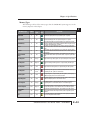
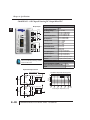
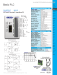
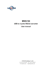
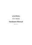
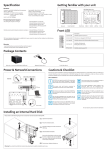
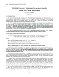
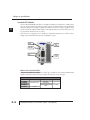
Chapter 2: Specifications
Standard CPU Modules
1
2
3
4
5
6
7
8
9
10
11
12
13
14
A
B
C
D
2–4
The Standard CLICK CPU modules are available with different combinations of built-in I/O
types (i.e. DC input/DC output, DC input/relay output, and AC input/relay output). With the
14 built-in I/O points (8 inputs/6 outputs), the CPU can be used as a ready-to-go PLC control
system without any additional I/O modules. The CPU module just needs 24 VDC, but it can
be expanded in the future if the need arises.
They also have an RS-485 port for Modbus and ASCII communications, and the battery
backup feature which will retain the data in SRAM for 5 years.
PLC Mode
Switch
C0-01DD1-D
8 Discrete
Input
Points
LED Status
Indicators
PWR
RUN
ERR
PORT1
TX1
RX1
Communication
Ports
TX2
6 Discrete
Output
Points
RX2
PORT2
PORT3
RS-485
TX3
RX3
Built-in I/O (Standard CPUs)
There are four different configurations of I/O types available for the Standard CLICK CPU
modules. The table below lists the part numbers showing the various I/O types.
Standard CLICK CPUs
Part Number
C0-01DD1-D
C0-01DD2-D
C0-01DR-D
C0-01AR-D
Discrete Input Type Discrete Output Type External Power
8 DC (sink/source)
8 AC
6 DC (sink)
6 DC (source)
6 Relay
24 VDC (required
for all CPUs)
CLICK PLC Hardware User Manual, 4th Ed. – C0-USER-M
Chapter 2: Specifications
Memory Types
The following is the list of the memory types that the CLICK PLC system supports. See the
memory map later in this chapter.
Symbol
Data
Type
Input Point
X
Bit
The Discrete Input points are represented by the "X" symbol.
Output Point
Y
Bit
The Discrete Output points are represented by the "Y" symbol.
Control Relay
C
Bit
Timer
T
Bit
Counter
CT
Bit
System Control
Relay
SC
Bit
Data Register
DS
Integer
Single word integer data registers are represented by the "DS" symbol.
Data Register
DD
Integer2
Double word integer data registers are represented by the "DD" symbol.
Data Register
DH
HEX
Single word Hex data registers are represented by the "DH" symbol.
Data Register
DF
Floating
Point
Data Floating Point registers are IEEE format Real number values represented by the "DF" symbol as 32 bit words.
Input Register
XD
HEX
The Input Registers, represented by the "XD" symbol, contain groups
of Discrete Input points in a 16 bit word format.
Output Register
YD
HEX
The Output Registers, represented by the "YD" symbol, contain groups
of Discrete Output points in a 16 bit word format.
Timer Register
TD
Integer
The Timer Registers, represented by the "TD" symbol, contain the corresponding Timer's accumulative value in a 16 bit data register.
Counter Register
CTD
Integer2
The Counter Registers, represented by the "CTD" symbol, contain the
corresponding Counter's accumulative value in a 32 bit data register.
System Data
Register
SD
Integer
The internal System Data Registers, represented by the "SD" symbol,
are pre-defined words which represent the status of specific system
functions.
Text
TXT
Text
The Text data registers, represented by the "TXT" symbol, are used to
store and manipulate ASCII text data.
Memory Type
S/W
Icon
Definition
The Control Relay bits are represented by the "C" symbol. These internal bits are typically used for ladder program control. They do not represent any real world inputs or outputs.
The Timers are represented by the "T" symbol. The Timer status bit is
used to indicate when the Current Value of the timer equals its Preset
Value.
The Counters are represented by the "CT" symbol. The Counter status
bit is used to indicate when the Current Value of the counter equals its
Preset Value.
The internal System Control Relays, represented by the "SC" symbol,
are pre-defined bits which represent the status of specific system functions.
CLICK PLC Hardware User Manual, 4th Ed. – C0-USER-M
1
2
3
4
5
6
7
8
9
10
11
12
13
14
A
B
C
D
2–13
Chapter 2: Specifications
C0-01DD2-D – 8 DC Input/6 Sourcing DC Output Micro PLC
Wiring Diagram
C0-01DD2-D
24VDC
C1
+
X1
X2
+
X3
X4
RUN
C2
ERR
X5
X6
PORT1
X7
TX1
X8
C0-01DD2-D Built-in I/O Specifications - Inputs
Inputs per Module
Operating Voltage Range
Input Voltage Range
Input Current
Maximum Input Current
+
PWR
+
Input Impedance
ON Voltage Level
RX1
V1
Y1
L
RX2
Y2
L
Y3
L
Y4
L
PORT2
RS-485
PORT3
V2
TX3
Y5
L
RX3
Y6
L
OFF Voltage Level
+
TX2
24VDC
+
Minimum ON Current
Maximum OFF Current
OFF to ON Response
CO
ON to OFF Response
NOTE: When using Standard CPUs, you
must use CLICK programming software
version V1.20 or later.
Status Indicators
Commons
8 (Sink/Source)
24 VDC
21.6 - 26.4 VDC
X1-2: Typ 5 mA @ 24 VDC
X3-8: Typ 4 mA @ 24 VDC
X1-2: 6.0 mA @ 26.4 VDC
X3-8: 5.0 mA @ 26.4 VDC
X1-2: 4.7 k⏲ @ 24 VDC
X3-8: 6.8 k⏲ @ 24 VDC
X1-2: > 19 VDC
X3-8: > 19 VDC
X1-2: < 4 VDC
X3-8: < 7 VDC
X1-2: 4.5 mA
X3-8: 3.5 mA
X1-2: 0.1 mA
X3-8: 0.5 mA
X1-2: Typ 5 μs Max 20 μs
X3-8: Typ 2 ms Max 10 ms
X1-2: Typ 5 μs Max 20 μs
X3-8: Typ 3 ms Max 10 ms
Logic Side (8 points, green LED)
2 (4 points/common) Isolated
General Specifications
Current Consumption at 24VDC
Terminal Block Replacement Part No.
Weight
140 mA
C0-16TB
5.0 oz (140 g)
Equivalent Input Circuit
C0-01DD2-D Temperature Derating Chart
Internal Module Circuitry
+
Optical Isolator
INPUT
X1-X4
Typical
Inputs
6
+
24 VDC
4
2
C1 COM
To X2-X4
commons
+
8
Points
1
2
3
4
5
6
7
8
9
10
11
12
13
14
A
B
C
D
0
Optical Isolator
INPUT
X5-X8
Typical
0
32
10
50
30
85
40
104
50 55 °C
122 131 °F
Surrounding Air Temperature (°C/°F)
+
2–38
20
68
24 VDC
C2 COM
To X6-X8
commons
CLICK PLC Hardware User Manual, 4th Ed. – C0-USER-M
Chapter 3: Installation and Wiring
Wiring Guidelines
Power Input Wiring to CLICK Power Supply
Connect the AC power source input wiring to the Click power supply (the Click power supply
voltage and current requirements are listed in chapter 2). If you are not using a CLICK power
supply, be sure to meet that supply’s requirements.
Do not apply power at this time. Observe all precautions stated earlier in this manual.
Warning: Once the power wiring is connected, secure the terminal block cover in the closed position.
When the cover is open there is a risk of electrical shock if you accidentally touch the connection
terminals or power wiring.
Power Input Wiring to Click CPU
Connect the 24 VDC power source input wiring to the 4-pin 24 VDC input connector located
on the bottom panel of the Click PLC. Do not apply power at this time. Observe all precautions
stated earlier in this manual.
CLICK CPU
CLICK Power Supply
24VDC
0V
24VDC
0V
G
G
CLICK PLC Hardware User Manual, 4th Ed. – C0-USER-M
3–17
A
2
3
3
3
3
3
3
3
3
3
3
3
3
3
3
3
3
Chapter 3: Installation and Wiring
Powering I/O Circuits
In most applications, it will be necessary to power the input devices from one power source, and
to power output loads from another source. Loads often require high-energy AC power, while
input sensors use low-energy DC. If a machine operator is likely to come in close contact with
input wiring, then safety reasons also require isolation from high-energy output circuits.
For the DC input/output circuits, you can use the same power source as the CPU module (and
I/O modules). However, you lose the isolation between the logic circuits and the input/output
circuits. (For AC input/output circuits, you don’t need to worry about sharing the 24VDC.)
Power Supply
CPU Module
Input Module
Output Module
Logic
Circuit
Logic
Circuit
24VDC
0VDC
Logic Circuit
Lose
Isolation
Input
Circuit
Isolation Boundary
Output
Circuit
Input
Circuit
Load
Output
Circuit
Load
To keep the isolation between the logic circuits and the input/output circuits, we recommend
using another power supply for the DC input and output circuits.
Power Supply
CPU Module
Input Module
Output Module
Logic
Circuit
Logic
Circuit
24VDC
0VDC
Logic Circuit
Keep
Isolation
Input
Circuit
Output
Circuit
Input
Circuit
Output
Circuit
Isolation Boundary
Load
Power
Supply
Load
24VDC
0VDC
CLICK PLC Hardware User Manual, 4th Ed. – C0-USER-M
3–25
A
2
3
3
3
3
3
3
3
3
3
3
3
3
3
3
3
3
Chapter 3: Installation and Wiring
Sinking/Sourcing Concepts
Before wiring field devices to the PLC I/O, it’s necessary to have a basic understanding of
sinking and sourcing concepts. Use of these terms occurs frequently in input or output circuit
discussions. The purpose of this section is to explain the terms. The short definitions are as
follows:
A
2
3
3
3
3
3
3
3
3
3
3
3
3
3
3
3
3
Sinking = Path to supply ground (–) or switching ground
Sourcing = Path to supply source (+) or switching +V
+
–
These terms only apply to DC circuits, not AC circuits. Input and output points that are either
sinking or sourcing can conduct current in only one direction. This means it is possible to wire
the external supply and field device to the I/O point with current trying to flow in the wrong
direction, in which case the circuit will not operate.
PLC
The diagram on the left shows a sinking PLC input. To
Input
properly connect the external supply, connect it so the
(sinking)
input provides a path to ground (–). Start at the PLC input
Input
terminal, follow through the input sensing circuit, exit at
Sensing
the common terminal, and connect the supply (–) to the
common terminal.
Common
The switch between the supply (+) and the input completes
the circuit. Current flows in the direction of the arrow when the switch is closed. By applying
the circuit principle above to the four possible combinations of input/output sinking/sourcing
types, we have the four circuits as shown below.
Sinking Input
Sinking Output
Input
PLC
PLC
Output
Load
+
–
+
Common
Input
Sensing
Common
+
3–26
–
Common
Sourcing Output
Sourcing Input
–
Output
Switch
Input
PLC
Input
Sensing
PLC
Common
+
Output
Switch
Output
–
Load
CLICK PLC Hardware User Manual, 4th Ed. – C0-USER-M