1
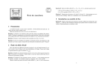
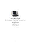
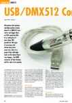
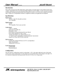
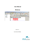
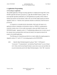
Cem Celik
[email protected]
Lima Endustriyel Bilgisayar
www.lima.com.tr
Istanbul-Turkey
June 2004
Using PS/2 Keyboards in Embedded Systems
Reasons to use a PS/2 Keyboard
The keyboards have always been the most
favorite units for data input to the
computers. The PC AT keyboard has not
changed electronically and protocol-wise
since the announcement of the first IBM PC
AT in 1984. It has evolved into its current
layout and connector with IBM PS/2 series
in 1987, and thus has been started to be
called as the PS/2 Keyboard.
The fact that this de-facto standard has not
changed for almost 20 years has created
two very positive results:
•
Low Prices (< 4 USD !),
•
Alternative Input Units using PS/2 compatible
interface. Most of Laser / CCD Scanners and
barcode / magnetic slot readers utilize PS/2
interface.
If one takes a close look at PS/2 keyboards; it will be seen that they consist of matrix keypads
(whose size has grown up to 8 rows by 16 columns) and a controller (such as Intel 8048)
which encodes the row-column information. Our PCs have a complimentary controller (such
as Intel 8042), which acts as a ‘host’ and decodes this information. An embedded system
targeted for PS/2 connectivity should realize the functions of this decoder.
The specifics of ‘Host’ – Keyboard (encoder) protocol are given in the articles provided by
Adam Chapweske in (1) & (2).
Two properties of this protocol are important for the embedded systems:
1. The communication is binary, synchronous and serial based: Only two channels
(CLOCK and DATA) are sufficient.
It is a very common practice to connect matrix keypads directly to the input/output
channels of the embedded systems used for automation. For example, JKmicro
provides a 4x4 (16 keys) matrix keypad solution complete with the hardware and
software driver for the FlashLite186 single board computer that is used in this article.
Although being very easy to implement, the downside of the matrix keypads is their
requirement for channels equal to the number of rows plus columns. Thus,
FlashLite186’s 4x4 keypad solution requires 8, a 101 keys unit (similar to PS/2
keyboard) would require a minimum of 21 input/output channels. This is a very
demanding requirement when you think that a FlashLite186 has only 44 such I/Os.
In short, the fact that PS/2 keyboard’s hardware protocol is serial and thus needs only
two pins is an important advantage. Designing a tailored encoder circuit for matrix
keypads is a widely used solution, but I am sure that they cost a lot more than 4 US
Dollars.
2. Communication is two-sided: In addition to the expected data flow from keyboard’s
encoder to the ‘host’ (PC), the host can send commands to it for adjusting certain
functions.
When we take a look at the commands that can be sent; it will be seen that they are
used to control LEDs (Num/Caps/Scroll Lock) and to setup the typematic rates. We
can assume that we will not need these adjustments in embedded systems and make
provisions for only one-sided communication from keyboard to the host.
This is exactly what has been tested in this article to reduce the development work
and CPU load.
Connections and the Protocol
Due to above summarized advantages; there are a lot of PS/2 keyboard related solutions for
various platforms in the Internet. Craig Peacock presents an application developed for
68HC705 in (3). This article also contains lots of detailed info about PS/2 keyboards. Atmel
has a sample solution developed for its AVR processor, written in ‘C’ (4).
There are two important preparations that need to be completed before connecting a PS/2
keyboard to any controller:
1)
A regulated, +5VDC power needs to be
supplied to the keyboard. The power
requirement can go up to 100mA and one
needs to ensure that the GNDs of the power
supply and the controller are common.
2) DATA and CLOCK signals are “open
collector” type: they need to be “pulled-up” to
5VDC via 10kOhm resistors. Remember that
a logical “0” generates a 5V signal, while a
logical “1” is observed as 0V !
Each key pressed causes a packet of data to be output by the encoder. Each data packet is
output during 11 cycles of CLOCK, therefore can be interpreted to be containing 11 bits : 1
start bit (= 0), 8 data bits (one byte), 1 parity (= 0 or =1) and 1 stop (=1) bit.
The signals that will be observed on CLOCK and DATA pins, when ‘Q’ is pressed are shown
below. This diagram is taken from Adam Chapweske’s article (1). ‘Q’ key is encoded with an
ASCII value of 31 (“15” as hexadecimal and “00010101” as binary).
The conclusions to be derived from the wave representations of the communications protocol
are given below:
CLOCK signal is generated
only during the data
transmission period: In
other words, this signal is
suitable for an interrupt-based
application.
Correct DATA values are
generated only after
CLOCK signal level has
gone down to 0V:
Interrupt routine should read
the DATA bit only during this
stage.
Key Codes
If we take a close look on our keyboard usage; we will notice that it consists of several steps.
Even if we press a single key; key pressing is the obvious event. Key-up is the second one
which triggers its own stream of data. Repeating the generated key codes (after a certain
delay), generating different code combinations when a key is pressed with secondary keys
such as [SHIFT], [ALT], [ALTGR], and [CTRL] are the other functions the encoder fulfills.
Craig Peacock’s article (3) gives a very useful diagram for the codes generated by a keyboard
in US English layout :
This diagram should warn a developer about two issues:
• Some keys generate two, a few such as [PRT SCR] and [PAUSE] generate more
characters.
• The codes need to be decoded (interpreted) as per the layout: For example the ‘Q’
key (15h) should be decoded as ‘F’ when using a “Turkish – F Keyboard”.
A Test Application for JKmicro’s FlashLite186
In this test study, FlashLite186 has been used. It is an industrial, single board computer
manufactured by JKmicro (www.jkmicro.com), has a 33Mhz 80186 compatible RDC8822
processor and comes with a preloaded DOS compatible OS. It is very compact in size and has
an extended working temperature range of -20 to +85 °C. An unregulated power supply with
2W, 7 to 34 VDC can be used if needed. Its detailed specification can be accessed from:
http://www.jkmicro.com/products/flashlite186.html
Since the operating system is DOS (compatible); one can use many of the conventional (old)
development environments. In this study, Borland C/C++ V.4.52 has been used. The
application has been installed and then launched in a FlashLite186 with HyperTerminal using
its serial port named “console”. This name has been
chosen deliberately because all “console” interactions
such as keyboard inputs (‘getch’) and screen outputs
(‘printf’) are diverted to this port at BIOS level.
FlashLite186 has 44 channels of digital I/0. In the test
application, two of the I/Os grouped under PORTC
(located within J9 connector) have been used. J9
connector also has a pin to accept a signal to trigger
interrupt INT2. CLOCK signal has been connected to
this INT2 in addition to pin 0 of PORTC, to facilitate a
simpler and cleaner programming algorithm by using
this interrupt.
The
application’s
interrupt
routine is triggered when
CLOCK
signal’s
level
is
changing from 0 to 5V. This
phase has been shown with the
yellow portion of clock waves.
The DATA bit’s value needs to
be read only when CLOCK is
0V. Therefore, the interrupt
routine needs to wait until that
stage, as shown with the red
portions of the waves.
Two ‘C’ functions collecting the data bits as per this diagram and decoding them are given
below:
/***********************************************************/
/* ps2_int: INT driven service routine that collects 10
*/
/* bits that make up a scan code sent by a PS2 encoder.
*/
/* It does not check the validity of parity or stop bits
*/
/***********************************************************/
void interrupt ps2_int(void)
{
unsigned char retry = 0, binp;
unsigned static char bkey = 0, bcount = 0;
if (bcount < 10)
{
// Wait until CLOCK signal is down (0V)
while ( ((binp = inportb(0x602)) & 1) && (retry++ < PS2_WAIT) );
if ( retry < PS2_WAIT )
{
if ( (bcount < 8) && (binp & 2)) bkey = bkey + bits[bcount];
bcount++;
} else {
// CLOCK signal did not go down - ERROR
bcount = 0;
bkey
= 0;
}
} else {
// 10. bit is received
ps2_decode(bkey);
bcount = 0;
bkey
= 0;
}
// Selective End of Interrupt for INT2
outport(EOI, 0x000E );
}
- Decode the key
/***********************************************************/
/*
ps2_decode: Decodes characters collect by ps2_int into*/
/* key and shift code buffers. It increments character
*/
/* count (charcount) by checking the time interval
*/
/* between the last two calls (stored in ps2_clock)
*/
/*
shiftcode bits are set as below:
*/
/*
0 : Left / Right Shift
*/
/*
1 : Left / Right Control
*/
/*
2 : Left / Right Alt
*/
/*
3 : Extended Key Flag (key starts with E0)
*/
/***********************************************************/
void ps2_decode(unsigned char keyin)
{
#define PS2_RATE 3
//Decode key or shift code
switch (keyin)
{
case 0x0://NULL
break;
case 0xF0://Key UP identifier
break;
case 0xE0://Extended key
shiftcode[charcount] = shiftcode[charcount] | 8;
break;
case 0x11://Left or Right Alt
shiftcode[charcount] = shiftcode[charcount] | 4;
break;
case 0x12://Left SHIFT
shiftcode[charcount] = shiftcode[charcount] | 1;
break;
case 0x14://Left or Right CONTROL
shiftcode[charcount] = shiftcode[charcount] | 2;
break;
case 0x59://Right SHIFT
shiftcode[charcount] = shiftcode[charcount] | 1;
break;
default :
keycode[charcount] = keyin;
break;
}
if ( (keycode[charcount] != 0) && \
(labs(biostime(0, 0L) - ps2_clock ) >= PS2_RATE ))
{
if (charcount < PS2_MAX)
{
charcount++;
shiftcode[charcount] = 0;
keycode[charcount] = 0;
}
}
// Update last decoding time
ps2_clock = biostime(0, 0L);
}
You can download the full application from the below link:
http://www.lima.com.tr/Support/JKSupportE.asp
If the “PS2Test” program is compiled
with the ‘#define DEBUG’ definition,
it dumps the bit sequences.
The sample dump shows three
bytes that are received after
pressing and releasing ‘Q’:
The first byte 15h represents the key
pressed; F0h signals that the key is
now up. The last 15h tells that the
key released was ‘Q’.
The application is also successful in
decoding PS/2 laser scanner inputs.
Conclusion
PS/2 keyboard’s electronic protocol can be easily realized with embedded systems. This
alternative should not be forgotten for cases needing to save I/O pins or require utilizing
alternative input devices such as laser scanners or slot readers.
References
1) Adam Chapweske - PS/2 Mouse/Keyboard Protocol, 1999
2) Adam Chapweske - The AT-PS/2 Keyboard Interface, 2001
3) Craig Peacock - Interfacing the AT keyboard, 19 Agu. 2001
(www.beyondlogic.org/keyboard/keybrd.htm)
4) Atmel - AVR313: Interfacing the PC AT Keyboard ,
http://www.atmel.com/atmel/acrobat/doc1235.pdf
5) JKmicro – FlashLite186 User’s Manual
http://www.jkmicro.com/documentation/pdf/FL186_man14.pdf
Cem Çelik
Lima Endustriyel Bilgisayar
www.lima.com.tr
Istanbul - June 2004